- Download PDF Manual
-
vehicle and the trailer such that the following four ratings are not exceeded: 1. GVWR 2. GTW 3. GAWR 4. Tongue weight rating for the trailer hitch utilized (This requirement may limit the ability to always achieve the 10% to 15% range of tongue weight as a percentage of total trailer weight).
Towing Requirements — Tires − Do not attempt to tow a trailer while using a compact
spare tire.
− Proper tire inflation pressures are essential to the safe and satisfactory operation of your vehicle. Refer to the Tires–General Information section of this manual on Tire Pressures for proper tire inflation procedures.
− Also, check the trailer tires for proper tire inflation
pressures before trailer usage.
− Check for signs of tire wear or visible tire damage before towing a trailer. Refer to the Tires–General Information section of this manual on Tread Wear Indicators for the proper inspection procedure.
− When replacing tires refer to the Tires–General Infor- mation section of this manual on Replacement Tires for proper tire replacement procedures. Replacing tires with a higher load carrying capacity will not increase the vehicle’s GVWR and GAWR limits.
Towing Requirements — Trailer Brakes − Do not interconnect the hydraulic brake system or vacuum system of your vehicle with that of the trailer. This could cause inadequate braking and possible personal injury.
− An electronically actuated trailer brake controller is required when towing a trailer with electronically actuated brakes. When towing a trailer equipped with a hydraulic surge actuated brake system, an electronic brake controller is not required.
− Trailer brakes are recommended for trailers over 1,000
lbs (454 kg) and required for trailers in excess of 2,000
lbs (907 kg).STARTING AND OPERATING 335
CAUTION!
If the trailer weighs more than 1,000 lbs (454 kg) loaded, it should have its own brakes and they should be of adequate capacity. Failure to do this could lead to accelerated brake lining wear, higher brake pedal effort, and longer stopping distances.
336 STARTING AND OPERATING
WARNING!
Do not connect trailer brakes to your vehicle’s hy- draulic brake lines. It can overload your brake sys- tem and cause it to fail. You might not have brakes when you need them and could have an accident. Towing any trailer will increase your stopping dis- tance. When towing you should allow for additional space between your vehicle and the vehicle in front of you. Failure to do so could result in an accident.
Towing Requirements — Trailer Lights & Wiring Whenever you pull a trailer, regardless of the trailer size, stop lights and turn signals on the trailer are required for motoring safety. The Trailer Tow Package may include a 4 and 7 pin wiring harness. Use a factory approved trailer harness and connector.
NOTE: Do not cut or splice wiring into the vehicles wiring harness. The electrical connections are all complete to the vehicle but you must mate the harness to a trailer connector. Refer to the following illustrations.
4 - Pin Connector
STARTING AND OPERATING 337
If using a manual transmission vehicle for trailer towing, all starts must be in FIRST gear to avoid excessive clutch slippage. Towing Tips — Automatic Transmission The “D” range can be selected when towing. However, if frequent shifting occurs while in this range, the “TOW HAUL” or “OD/OFF” range should be selected. NOTE: Using the “TOW HAUL” or “OD/OFF” range while operating the vehicle under heavy operating con- ditions will improve performance and extend transmis- sion life by reducing excessive shifting and heat build up. This action will also provide better engine braking. The automatic transmission fluid and filter should be changed if you REGULARLY tow a trailer for more than 45 minutes of continuous operation. See Schedule “B” in section 8 of this manual for transmission fluid change intervals.
7- Pin Connector
Towing Tips Before setting out on a trip, practice turning, stopping and backing the trailer in an area away from heavy traffic.
338 STARTING AND OPERATING
NOTE: Check the automatic transmission fluid level before towing. Towing Tips — Tow/Haul (If Equipped) To reduce potential for automatic transmission overheat- ing, turn the “TOW HAUL OD/OFF” feature ON when driving in hilly areas or shift the transmission to Drive position 2 on more severe grades. Towing Tips — Electronic Speed Control (If Equipped) − Don’t use in hilly terrain or with heavy loads. − When using the speed control, if you experience speed drops greater than 10 mph (16 km/h), disengage until you can get back to cruising speed.
− Use speed control in flat terrain and with light loads to
maximize fuel efficiency.
Towing Tips — Cooling System To reduce potential for engine and transmission over- heating, take the following actions: − City Driving When stopped for short periods of time, put transmission in neutral and increase engine idle speed. − Highway Driving Reduce speed. − Air Conditioning Turn off temporarily. − refer to Cooling System Operating information in the Maintenance section of this manual for more informa- tion.
Trailer Towing Mirrors — If Equipped These mirrors are designed with an adjustable mirror head to provide a greater vision range when towing extra-wide loads. To change position inboard or out- board, the mirror head should be rotated (flipped Out or In). A small blindspot mirror is integrated onto the main mirror surface. NOTE: rearward prior to entering an automated car wash.
Fold the 7 x 10 inch trailer towing mirrors
CAUTION!
Do not attempt to fold the 7 x 10 inch trailer towing mirrors forward. The 7 x 10 inch trailer towing mirrors are not designed to be folded forward and doing so will damage the mirrors and/or vehicle.
STARTING AND OPERATING 339
Blindspot Mirror
340 STARTING AND OPERATING
Trailer Towing Position
SNOWPLOW
Dodge Power Wagon Models
NOTE: Do not use Dodge Power Wagon Models for snowplow applications.
WARNING!
and other
aftermarket
Snowplows equipment should not be added to the front end or your vehicle. The airbag crash sensors may be affected by the change in the front end structure. The airbags could deploy unexpectedly or could fail to deploy during a collision resulting in serious injury or death.
CAUTION!
RECREATIONAL TOWING — 4–WHEEL DRIVE VEHICLES (BEHIND MOTORHOME, ETC.)
STARTING AND OPERATING 341
Using this vehicle for snowplow applications can cause damage to the vehicle.
WARNING!
Attaching a snowplow to this vehicle could ad- versely affect performance of the airbag system in an accident. Do not expect that the airbag will perform as described earlier in this manual
CAUTION!
Internal damage to the transfer case will occur if a front or rear wheel lift is used when recreational towing.
NOTE: The transfer case must be shifted into Neutral (N) for recreational towing. Automatic transmissions must be placed in P (Park) position for recreational towing. Manual transmissions must be left in gear (not in neutral) for recreational towing. Refer below for the proper transfer case Neutral shifting procedure for your vehicle.
342 STARTING AND OPERATING
Recreational Towing Procedure — Manual Shift Transfer Case — If Equipped Use the following procedure to prepare your vehicle for recreational towing:
CAUTION!
It is necessary to follow these steps to be certain that the transfer case is fully in N (NEUTRAL) before recreational towing to prevent damage to internal parts.
1. Bring the vehicle to a complete stop. 2. Shut OFF the engine. 3. Depress the brake pedal. 4. Shift automatic transmission to N (NEUTRAL), or depress the clutch on manual transmissions.
5. Shift transfer case lever into N (NEUTRAL). 6. Start the engine. 7. Shift automatic transmission into Reverse (R). 8. Release brake pedal for five seconds and ensure that there is no vehicle movement. 9. Repeat steps 7 and 8 with the transmission in Drive (D). 10. Shut OFF the engine and place the ignition key to the unlocked OFF position. 11. Shift automatic transmission into P (PARK). 12. Apply the parking brake. 13. Attach vehicle to tow vehicle with tow bar. 14. Release the parking brake.
CAUTION!
Damage to the automatic transmission may occur if the transmission is shifted into P (PARK) with the transfer case in N (NEUTRAL) and the engine RUN- NING. With the transfer case in N (NEUTRAL) ensure that the engine is OFF prior to shifting the transmission into P (PARK)
Returning to Normal Operation — Manual Shift Transfer Case Use the following procedure to prepare your vehicle for normal usage: 1. Bring the vehicle to a complete stop. 2. Shut OFF the engine. 3. Depress the brake pedal.
STARTING AND OPERATING 343
4. Shift automatic transmission to N (NEUTRAL), or depress the clutch on manual transmissions. 5. Shift transfer case lever to desired position. 6. Shift automatic transmission into P (Park).
WARNING!
You or others could be injured if you leave the vehicle unattended with the transfer case in the N (NEUTRAL) position without first fully engaging the parking brake. The transfer case N (NEUTRAL) position disengages both the front and rear drive- shafts from the powertrain and will allow the ve- hicle to move regardless of the transmission posi- tion. The parking brake should always be applied when the driver is not in the vehicle.
344 STARTING AND OPERATING
CAUTION!
• Do not use a bumper mounted clamp-on tow bar on your vehicle. The bumper face bar will be damaged. • Do not disconnect the rear driveshaft because fluid will leak from the transfer case and damage the internal parts.
TRACTION When driving on wet or slushy roads, it is possible for a wedge of water to build up between the tire and road surface. This is known as hydroplaning and may cause partial or complete loss of vehicle control and stopping ability. To reduce this possibility, the following precau- tions should be observed: 1. Slow down during rainstorms or when roads are slushy.
2. Slow down if road has standing water or puddles. 3. Replace tires when tread wear indicators first become visible. 4. Keep tires properly inflated. 5. Maintain sufficient distance between your vehicle and the car in front to avoid a collision in a sudden stop.
EQUIPMENT IDENTIFICATION PLATE The equipment Identification Plate is located on the hood inner surface. The following information about your vehicle is dis- played on this plate: Model, Wheelbase, Vehicle Identifi- cation Number, Truck Order Number, and code numbers with descriptions of all production and special equip- ment on the truck as shipped from the factory. NOTE: Always refer to the Equipment Identification Plate When Ordering Parts.
WHAT TO DO IN EMERGENCIES
CONTENTS
䡵 Hazard Warning Lights . . . . . . . . . . . . . . . . . . 346
䡵 Adding Fuel . . . . . . . . . . . . . . . . . . . . . . . . . . 347
䡵 Jack Location . . . . . . . . . . . . . . . . . . . . . . . . . . 348
▫ All Models . . . . . . . . . . . . . . . . . . . . . . . . . . 348
䡵 Changing A Flat Tire . . . . . . . . . . . . . . . . . . . . 349
▫ Removing The Spare Tire . . . . . . . . . . . . . . . . 349
▫ Tire Changing Procedure . . . . . . . . . . . . . . . . 350䡵 Hoisting . . . . . . . . . . . . . . . . . . . . . . . . . . . . . 356
䡵 Jump-Starting . . . . . . . . . . . . . . . . . . . . . . . . . 356
䡵 Freeing A Stuck Vehicle . . . . . . . . . . . . . . . . . . 359
䡵 Emergency Tow Hooks — If Equipped . . . . . . . . 360
䡵 Towing A Disabled Vehicle . . . . . . . . . . . . . . . . 360
▫ 4-Wheel-Drive Vehicles . . . . . . . . . . . . . . . . . 361
䡵 Winch Usage . . . . . . . . . . . . . . . . . . . . . . . . . . 361346 WHAT TO DO IN EMERGENCIES
HAZARD WARNING LIGHTS The Hazard Warning switch is mounted on the top of the steering column as shown in the illustration.
Hazard Light Warning Switch
To engage the Hazard Warning lights, depress the button on the top of the steering column. When the Hazard Warning switch is activated, all directional turn signals will flash off and on to warn oncoming traffic of an emergency. Push the button a second time to turn off the flashers. This is an emergency warning system and should not be used when the vehicle is in motion. Use it when your vehicle is disabled and is creating a safety hazard for other motorists. When you must leave the vehicle to seek assistance, the Hazard Warning lights will continue to operate even though the ignition switch is OFF. NOTE: With extended use, the Hazard Warning lights may discharge your battery.
ADDING FUEL The fuel tank filler tube has a restricting door about 2
inches (50 mm) inside the opening. If using a portable fuel container, it should have a flexible nozzle long enough to force open the restricting door.WARNING!
A fire may result if gasoline is pumped into a portable container that is in a vehicle or on a truck bed. You could be burned. Always place gas contain- ers on the ground while filling.
WHAT TO DO IN EMERGENCIES 347
WARNING!
Remove the gas cap slowly to prevent fuel spray from the filler neck which may cause injury. The volatility of present gasolines may cause a build up of pressure in the fuel tank that may increase while you drive. This pressure can result in a spray of gasoline and/or vapors when you remove the cap from a hot vehicle. Removing the cap slowly allows the pressure to vent and prevents fuel spray. Never allow any lit smoking materials near the vehicles while removing the cap or filling the tank. Never add fuel to the vehicle when the engine is running.
348 WHAT TO DO IN EMERGENCIES
JACK LOCATION
All Models The jack and jack tools are stored under the passenger seat. Lift the flap on the side of the seat for access. Remove the jack and tools by loosening the thumb screw and sliding the assembly from under the seat.
WARNING!
The jack is designed to use as a tool for changing tires only. The jack should not be used to lift the vehicle for service purposes, unless suitable sup- ports are placed under the vehicle as a safety mea- sure. The vehicle should be jacked on a firm level surface only. Avoid ice or slippery areas.
WARNING!
After using the jack and tools, always reinstall them in the original carrier and location. While driving you may experience, abrupt stopping, rapid accelera- tion, or sharp turns. A loose jack, tools, bracket or other objects in the vehicle may move around with force, resulting in serious injury.
CHANGING A FLAT TIRE
Removing The Spare Tire Remove the spare tire before attempting to jack the truck. Attach the wheel wrench to the jack extension tube. Insert the tube through the access hole between the lower tailgate and the top of the bumper and into the winch mechanism tube. Rotate the wheel wrench handle coun- terclockwise until the spare tire is on the ground with enough cable slack to allow you to pull it out from under the vehicle. When the spare is clear, tilt the retainer at the end of the cable and pull it through the center of the wheel.
WHAT TO DO IN EMERGENCIES 349
It is recommended that you stow the flat or spare to avoid tangling the loose cable. NOTE: The winch mechanism is designed for use with the jack extension tube only. Use of an air wrench or other power tools is not recommended and can damage the winch.
350 WHAT TO DO IN EMERGENCIES
Tire Changing Procedure
WARNING!
Getting under a jacked-up vehicle is dangerous. The vehicle could slip off the jack and fall on you. You could be crushed. Never get any part of your body under a vehicle that is on a jack. Never start or run the engine while the vehicle is on a jack. If you need to get under a raised vehicle, take it to a service center where it can be raised on a lift.
Do not raise this vehicle using a bumper jack. The jack is designed as a tool for changing tires on this vehicle only. It is not recommended that the jack be used for service purposes or to lift more than one wheel at a time.
Preparations Park the vehicle on a firm level surface, avoiding ice or slippery areas. Set the parking brake and place the gear selector in PARK (automatic transmission) or REVERSE (manual transmission). On four-wheel drive vehicles, shift the transfer case to the “4L” position.
WARNING!
Do not attempt to change a tire on the side of the vehicle close to moving traffic. Pull far enough off the road to avoid the danger of being hit when operating the jack or changing the wheel. • Turn on the Hazard Warning Flasher.
• Block both the front and rear of the wheel diagonally oppo- site the jacking position. For example, front wheel is being changed, block the left rear wheel. • Passengers should not remain in the vehicle when the
the right
if
vehicle is being jacked.
WHAT TO DO IN EMERGENCIES 351
Instructions
WARNING!
raised.
Carefully follow these tire changing warnings to help prevent personal injury or damage to your vehicle: • Always park on a firm, level surface as far from the edge of the roadway as possible before raising the vehicle. • Block the wheel diagonally opposite the wheel to be • Apply the parking brake firmly before jacking. • Never start the engine with the vehicle on a jack. • Do not let anyone sit in the vehicle when it is on a • Do not get under the vehicle when it is on a jack. • Only use the jack in the positions indicated. • If working on or near a roadway, be extremely
jack.
careful of motor traffic.
Before raising the wheel off the ground, make sure that the jack will not damage surrounding truck parts and adjust the jack position as required.
If the jack will not lower by turning the dial NOTE: (thumb wheel) by hand, it may be necessary to use the jack drive tube in order to lower the jack.
352 WHAT TO DO IN EMERGENCIES
1. Remove the spare wheel, jack, and tools from storage. 2. Using the wheel wrench, loosen, but do not remove, the wheel nuts by turning them counterclockwise one turn while the wheel is still on the ground. 3. For Power Wagon, when changing the front wheel, assemble the jack drive tube to the jack and connect the drive tube to the extension tube. Place the jack under the axle as close to the tire as possible with the drive tubes extending to the front. Connect the jack tube extension and wheel wrench. When changing a rear wheel, assemble the jack drive tube to the jack and connect the drive tube to the extension tube. Place the jack under the axle between the spring and the shock absorber with the drive tubes extending to the rear. Connect the jack tube extension and wheel wrench.
WHAT TO DO IN EMERGENCIES 353
WARNING!
Raising the vehicle higher than necessary can make the vehicle unstable and cause an accident. It could slip off the jack and hurt someone near it. Raise the vehicle only enough to remove the tire.
5. Remove the wheel nuts and pull the wheel off. Install the spare wheel and wheel nuts with the cone shaped end of the nuts toward the wheel on the rear wheel models. 6. Using the wheel wrench, finish tightening the nuts using a crisscross pattern. Correct nut tightness is 135 ft. lbs. (183 N·m) torque.If in doubt about the correct tight- ness, have them checked with a torque wrench by your dealer or at a service station.
4. By rotating the wheel wrench clockwise, raise the vehicle until the wheel just clears the surface.
354 WHAT TO DO IN EMERGENCIES
WARNING!
A loose tire or jack thrown forward in a collision or hard stop could injure someone in the vehicle. Always stow the jack parts and the extra tire and wheel in the places provided.
7. Remove wheel blocks. Do not install chrome or alu- minum wheel center caps on the spare wheel. This may result in cap damage. 8. Lower the jack to its fully closed position. If the jack will not lower by turning the dial (thumb wheel) by hand, it may be necessary to use the jack drive tube in order to lower the jack. Stow the replaced tire, jack, and tools as previously described. 9. Adjust the tire pressure when possible.
NOTE: Do not oil wheel studs. For chrome wheels, do not substitute with chrome plated wheel nuts. Hub Caps The hub caps must be removed before raising the vehicle off the ground. For 2500/3500 single rear wheel (SRW) models, use the blade on the end of the lug wrench to pry the hub cap off. Insert the blade end into the pryoff notch and carefully pop off the hub cap with a back and forth motion.
CAUTION!
Use a back and forth motion to remove the hub cap. Do not use a twisting motion when removing the hub cap, damage to the hub cap finish may occur.
Wheel Nuts All wheel nuts should be tightened occasionally to elimi- nate the possibility of wheel studs being sheared or the bolt holes in the wheels becoming elongated. This is especially important during the first few hundred miles of operation to allow the wheel nuts to become properly set. All nuts should first be firmly seated against the wheel. The nuts should then be tightened to recom- mended torque. Tighten the nuts to final torque in increments. Progress around the bolt circle, tightening the nut opposite to the nut just previously tightened until final torque is achieved. Recommended torques are shown in the following chart. Disc Wheels
Type Nut Stud Size Torque Ft. Lbs.
Cone Flanged
9/16-18
9/16-18120-150
130-160Torque Newton Meters 160-200
190-220WHAT TO DO IN EMERGENCIES 355
To Stow The Flat Or Spare Turn the wheel so that the valve stem is down. Slide the wheel retainer through the center of the wheel and position it properly across the wheel opening. For convenience in checking the spare tire inflation, stow with the valve stem toward the rear of the vehicle. Attach the wheel wrench to the extension tube. Rotate the winch mechanism until the wheel is drawn into place against the underside of the vehicle. Continue to rotate until you feel the winch mechanism slip or click 3 or 4
times. It cannot be overtightened. Push against the tire several times to be sure it is firmly in place.356 WHAT TO DO IN EMERGENCIES
HOISTING A conventional floor jack may be used at the jacking locations, refer to the graphics that show jacking loca- tions. However, a floor jack or frame hoist must never be used on any other parts or the underbody.
CAUTION!
Never use a floor jack directly under the differential housing of a loaded truck or damage to your vehicle may result.
JUMP-STARTING You should not try to start your vehicle by pushing or towing. Vehicles equipped with an automatic transmis- sion cannot be started this way and pushing or towing a vehicle equipped with a manual transmission may over- heat and damage the catalytic converter. Also, there is a greater risk of an accident when a vehicle is being pushed or towed. If the vehicle has a discharged battery, booster cables may be used to obtain a start from a booster battery or the battery in another vehicle. This type of start can be dangerous if done improperly, so follow this procedure carefully.
WARNING!
Battery fluid is a corrosive acid solution; do not allow battery fluid to contact eyes, skin or clothing. Don’t lean over battery when attaching clamps or allow the clamps to touch each other. If acid splashes in eyes or on skin, flush contaminated area immedi- ately with large quantities of water. A battery generates hydrogen gas which is flam- mable and explosive. Keep flame or spark away from the vent holes. Do not use a booster battery or any other booster source that has a greater than 12 volt system, i.e. Do not use a 24 volt power source.
1. Remove all metal jewelry such as watch bands or bracelets which might make an unintended electrical contact.
WHAT TO DO IN EMERGENCIES 357
2. Park the booster vehicle within cable reach but with- out letting the vehicles touch. Set the parking brake on both vehicles, place the automatic transmission in Park or the manual transmission in Neutral, and turn the ignition OFF. 3. Turn off the heater, radio, and all unnecessary electri- cal loads. 4. Connect one end of a jumper cable to the positive terminal of the booster battery. Connect the other end of the same cable to the positive terminal of the discharged battery.
WARNING!
Do not permit vehicles to touch each other as this could establish a ground connection and personal injury could result.
358 WHAT TO DO IN EMERGENCIES
5. Connect the other cable, first to the negative terminal of the booster battery and then to the engine of the vehicle with the discharged battery. Make sure you have a good contact on the engine.
WARNING!
• Do not connect the cable to the negative post of the discharge battery. The resulting electrical spark could cause the battery to explode. • During cold weather when temperatures are be- low freezing point, electrolyte in a discharged battery may freeze. Do not attempt jump starting because the battery could rupture or explode. The battery temperature must be brought up above freezing point before attempting jump start.
6. Start the engine in the vehicle which has the booster battery, let the engine idle a few minutes, then start the engine in the vehicle with the discharged battery. 7. When removing the jumper cables, reverse the above sequence exactly. Be careful of the moving belts and fan.
WARNING!
Any procedure other than above could result in: 1. Personal injury caused by electrolyte squirting out the battery vent; 2. Personal injury or property damage due to battery explosion; 3. Damage to charging system of booster vehicle or of immobilized vehicle.
WHAT TO DO IN EMERGENCIES 359
FREEING A STUCK VEHICLE If vehicle becomes stuck in snow, sand, or mud, it can often be moved by a rocking motion. Move the gear selector rhythmically between DRIVE and REVERSE (automatic transmissions) and between 1st and RE- VERSE (manual transmissions), while applying slight pressure to the accelerator. In general, the least amount of accelerator pedal pressure to maintain the rocking motion without spinning the wheels or racing the engine is most effective. Racing the engine or spinning the wheels, due to the frustration of not freeing the vehicle, may lead to transmission over- heating and failure. Allow the engine to idle with the transmission selector in NEUTRAL for at least one minute after every five rocking-motion cycles. This will minimize overheating and reduce the risk of transmis- sion failure during prolonged efforts to free a stuck vehicle.
360 WHAT TO DO IN EMERGENCIES
EMERGENCY TOW HOOKS — IF EQUIPPED Your vehicle may be equipped with emergency tow hooks.
WARNING!
Chains are not recommended for freeing a stuck vehicle. Chains may break, causing serious injury or death.
WARNING!
Stand clear of vehicles when pulling with tow hooks. Tow straps and chains may break, causing serious injury.
CAUTION!
Tow hooks are for emergency use only, to rescue a vehicle stranded off road. Do not use tow hooks for tow truck hookup or highway towing. You could damage your vehicle.
TOWING A DISABLED VEHICLE Proper towing or lifting equipment is required to prevent damage to your vehicle. Use only tow bars and other equipment designed for the purpose, following equip- ment manufacturer’s instructions. Use of safety chains is mandatory. Attach a tow bar or other towing device to the main structural members of the vehicle—not to bumpers or associated brackets. State and local laws applying to vehicles under tow must be observed.
4-Wheel-Drive Vehicles
CAUTION!
To avoid damage to the transfer case while towing, always use the following method.
The manufacturer recommends towing with all wheels off the ground. Acceptable methods are to tow vehicle on a flatbed or with one end of vehicle raised and the opposite end on a towing dolly.
WHAT TO DO IN EMERGENCIES 361
WINCH USAGE (See page 256 for more information.)
MAINTAINING YOUR VEHICLE
CONTENTS
䡵 Engine Compartment— 5.7L . . . . . . . . . . . . . . . 366
䡵 Onboard Diagnostic System (OBD II) . . . . . . . . . 367
䡵 Emissions Inspection And MaintenancePrograms
. . . . . . . . . . . . . . . . . . . . . . . . . . . . 367
䡵 Dealer Service . . . . . . . . . . . . . . . . . . . . . . . . . 369
䡵 Replacement Parts . . . . . . . . . . . . . . . . . . . . . . 370
䡵 Maintenance Procedures . . . . . . . . . . . . . . . . . . 370
▫ Engine Oil . . . . . . . . . . . . . . . . . . . . . . . . . . 370
▫ Engine Oil Filter . . . . . . . . . . . . . . . . . . . . . . 374▫ Drive Belts — Check Condition And
Tensioner . . . . . . . . . . . . . . . . . . . . . . . . . . . 374
▫ Spark Plugs . . . . . . . . . . . . . . . . . . . . . . . . . 375
▫ Engine Air Cleaner Filter . . . . . . . . . . . . . . . . 375
▫ Engine Fuel Filter . . . . . . . . . . . . . . . . . . . . . 375
▫ Catalytic Converter . . . . . . . . . . . . . . . . . . . . 376
▫ Emission-Related Components . . . . . . . . . . . . 378
▫ Maintenance Free Battery . . . . . . . . . . . . . . . . 378
▫ Air Conditioner Maintenance . . . . . . . . . . . . . 379364 MAINTAINING YOUR VEHICLE
▫ Power Steering — Fluid Check . . . . . . . . . . . . 380
▫ Front Suspension Ball Joints . . . . . . . . . . . . . . 380
▫ Steering Linkage — Inspection . . . . . . . . . . . . 381
▫ Front Prop Shaft Lubrication . . . . . . . . . . . . . 382
▫ Body Lubrication . . . . . . . . . . . . . . . . . . . . . 382
▫ Windshield Wiper Blades . . . . . . . . . . . . . . . . 383
▫ Windshield Washers . . . . . . . . . . . . . . . . . . . 383
▫ Exhaust System . . . . . . . . . . . . . . . . . . . . . . 384
▫ Cooling System . . . . . . . . . . . . . . . . . . . . . . . 385
▫ Hoses And Vacuum/Vapor Harnesses . . . . . . . 389
▫ Brake System . . . . . . . . . . . . . . . . . . . . . . . . 389
▫ Clutch Hydraulic System . . . . . . . . . . . . . . . . 391
▫ Clutch Linkage . . . . . . . . . . . . . . . . . . . . . . . 391▫ Rear Axle And 4X4 Front Driving Axle Fluid
Level . . . . . . . . . . . . . . . . . . . . . . . . . . . . . . 391
▫ Transfer Case . . . . . . . . . . . . . . . . . . . . . . . . 392
▫ Front Drive Shaft . . . . . . . . . . . . . . . . . . . . . 392
▫ Manual Transmission . . . . . . . . . . . . . . . . . . 392
▫ Automatic Transmission . . . . . . . . . . . . . . . . 393
▫ Front Wheel Bearings . . . . . . . . . . . . . . . . . . 396
▫ Selection Of Lubricating Grease . . . . . . . . . . . 396
▫ Noise Control System Required Maintenance &Warranty . . . . . . . . . . . . . . . . . . . . . . . . . . . 397
▫ Appearance Care And Protection From
Corrosion . . . . . . . . . . . . . . . . . . . . . . . . . . . 401
䡵 Integrated Power Module . . . . . . . . . . . . . . . . . 405
䡵 Vehicle Storage . . . . . . . . . . . . . . . . . . . . . . . . 405䡵 Replacement Light Bulbs 䡵 Bulb Replacement
. . . . . . . . . . . . . . . . . 406
. . . . . . . . . . . . . . . . . . . . . . 407▫ Headlight (Halogen)/Front Park And Turn
Lights . . . . . . . . . . . . . . . . . . . . . . . . . . . . . 407
▫ Tail, Stop, Turn And Backup Lights . . . . . . . . . 410
▫ Center High-Mounted Stoplight With CargoLight . . . . . . . . . . . . . . . . . . . . . . . . . . . . . . 412
MAINTAINING YOUR VEHICLE 365
▫ Cab Top Clearance Lights — If Equipped . . . . 414
▫ Fog Lights . . . . . . . . . . . . . . . . . . . . . . . . . . 415
䡵 Fluids And Capacities . . . . . . . . . . . . . . . . . . . 417
䡵 Fluids, Lubricants And Genuine Parts . . . . . . . . 418
▫ Engine . . . . . . . . . . . . . . . . . . . . . . . . . . . . . 418
▫ Chassis . . . . . . . . . . . . . . . . . . . . . . . . . . . . 419366 MAINTAINING YOUR VEHICLE
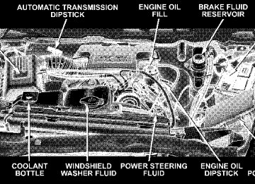
ENGINE COMPARTMENT— 5.7L
ONBOARD DIAGNOSTIC SYSTEM (OBD II) Your vehicle is equipped with a sophisticated onboard diagnostic system called OBD II. This system monitors the performance of the emissions, engine, and automatic transmission control systems. When these systems are operating properly, your vehicle will provide excellent performance and fuel economy, as well as engine emis- sions well within current government regulations. If any of these systems require service, the OBD II system will turn on the “Malfunction Indicator Light.” It will also store diagnostic codes and other information to assist your service technician in making repairs. Al- though your vehicle will usually be driveable and not need towing, see your dealer for service as soon as possible.
MAINTAINING YOUR VEHICLE 367
CAUTION!
Prolonged driving with the “Malfunction Indicator Light” on could cause further damage to the emis- sion control system. It could also affect fuel economy and driveability. The vehicle must be serviced before any emissions tests can be performed. If the “Malfunction Indicator Light” is flashing, severe catalytic converter damage and power loss will soon occur. Immediate service is required.
EMISSIONS INSPECTION AND MAINTENANCE PROGRAMS In some localities, it may be a legal requirement to pass an inspection of your vehicle’s emissions control system. Failure to pass could prevent vehicle registration.
368 MAINTAINING YOUR VEHICLE
For states which have an I/M (Inspection and Maintenance) requirement, this check verifies the following: the MIL (Malfunction Indicator Lamp) is functioning and is not on when the engine is running, and that the OBD (On Board Diagnostic) system is ready for testing. Normally, the OBD system will be ready. The OBD system may not be ready if your vehicle was recently serviced, if you recently had a dead battery, or a battery replacement. If the OBD system should be determined not ready for the I/M test, your vehicle may fail the test. Your vehicle has a simple ignition key actuated test which you can use prior to going to the test station. To check if your vehicle’s OBD system is ready, you must do the following: 1. Insert your ignition key into the ignition switch.
2. Turn the ignition to the ON position, but do not crank or start the engine. 3. If you crank or start the engine, you will have to start this test over. 4. As soon as you turn your key to the ON position, you will see your MIL symbol come on as part of a normal bulb check. 5. Approximately 15 seconds later, one of two things will happen:
a. The MIL light will blink for approximately 5 sec- onds and then remain on until the first engine crank or the key is turned off. This means that your vehicle’s OBD system is not ready and you should not proceed to the I/M station.
b. The MIL light will remain fully illuminated until the first engine crank or the key is turned off. This means that your vehicle’s OBD system is ready and you can proceed to the I/M station.
If your OBD system is not ready, you should see your dealer or repair facility. If your vehicle was recently serviced or had a battery failure or replacement, you may need to do nothing more than drive your vehicle as you normally would in order for your OBD system to update. A recheck with the above test routine may then indicate that the system is now ready. Regardless of whether your vehicle’s OBD system is ready or not ready, if the MIL symbol is illuminated during normal vehicle operation, you should have your vehicle serviced before going to the I/M station. The I/M station can fail your vehicle because the MIL symbol is on with the engine running.
MAINTAINING YOUR VEHICLE 369
DEALER SERVICE Your dealer has the qualified service personnel, special tools and equipment to perform all service operations in an expert manner. Service manuals are available which include detailed service information for your vehicle. Refer to these manuals before attempting any procedure yourself. NOTE: systems can result against you.
Intentional tampering with emissions control in civil penalties being assessed
370 MAINTAINING YOUR VEHICLE
WARNING!
You can be badly injured working on or around a motor vehicle. Do only that service work for which you have the knowledge and the proper equipment. If you have any doubt about your ability to perform a service job, take your vehicle to a competent mechanic.
REPLACEMENT PARTS Use of genuine Mopar威 parts for normal/scheduled maintenance and repairs is highly recommended to in- sure the designed performance. Damage or failures caused by the use of non-Mopar parts for maintenance and repairs will not be covered by the manufacturer’s warranty.
MAINTENANCE PROCEDURES The pages that follow contain the required maintenance services determined by the engineers who designed your vehicle. Besides the maintenance items for which there are fixed maintenance intervals, there are other items that should operate satisfactorily without periodic maintenance. However, if a malfunction of these items does occur, it could adversely affect the engine or vehicle performance. These items should be inspected if a malfunction is observed or suspected. Engine Oil
Checking Oil Level To assure proper lubrication of your vehicle’s engine, the engine oil must be maintained at the correct level. The best time to check the engine oil level is about 5 minutes after a fully warmed up engine is shut off or before starting the engine after it has sat overnight.
Checking the oil while the vehicle is on level ground will improve the accuracy of the oil level readings. Maintain the oil level between the ADD and SAFE markings on the dipstick. Adding one quart of oil when the reading is at the ADD mark will result in a SAFE reading on these engines.
MAINTAINING YOUR VEHICLE 371
Change Engine Oil
CAUTION!
Overfilling or underfilling the crankcase will cause oil aeration or loss of oil pressure. This could dam- age your engine.
Road conditions as well as your kind of driving affect the interval at which your oil should be changed. Check the following to determine if any apply to you: • Day or night temperatures are below 32°F (0°C). • Stop and go driving. • Extensive engine idling. • Driving in dusty conditions • Short trips of less than 10 miles (16.2 km)
372 MAINTAINING YOUR VEHICLE
speeds during hot weather, above 32°C (90°F)
• More than 50% of your driving is at sustained high • Trailer towing • Heavy Loading • Taxi, Police or delivery service (commercial service) • Off-road or desert operation • If equipped for and operating with E-85 (ethanol)
fuel.
If ANY of these apply to you then change your NOTE: engine oil every 3,000 miles (5 000 km) or 3 months, whichever comes first and follow schedule “B” of the ⬙Maintenance Schedules⬙ section of this manual. If none of these apply to you, then change your engine oil at every interval shown on schedule ⬙A⬙ of the ⬙Mainte- nance Schedules⬙ section of this manual.
Dusty Conditions Driving through dust-laden air increases the problems of keeping abrasive materials out of the engine. Under these conditions, special attention should be given to the engine air cleaner, the crankcase inlet air cleaner and the crankcase ventilation system. Make sure that these units are clean at all times. This will tend to reduce to a minimum the amount of abrasive material that may enter the engine. Engine Oil Selection For best performance and maximum protection under all types of operating conditions, the manufacture only recommends engine oils that are API certified and meet the requirements of DaimlerChrysler Material Standard MS-6395. Use Mopar or an equivalent oil meeting the specification MS-6395.
Engine Oil Identification (API) Symbol There is a symbol to aid you in selecting the proper engine oil.
This symbol means that the oil has been certified by the American Pe- troleum Institute (API). The manu- facturer only recommends API Cer- tified engine oils that meet the requirements of DaimlerChrysler Material Standard MS-6395. Use Mopar or an equivalent oil meeting
the specification MS-6395. Engine Oil Viscosity (SAE Grade) SAE 5W-20 engine oil is recommended for all operating temperatures. This engine oil improves low tempera- ture starting and vehicle fuel economy. Refer to your engine oil filler cap for the recommended engine oil viscosity for your vehicle.
MAINTAINING YOUR VEHICLE 373
For information on engine oil filler cap location, see the Engine Compartment illustration in this section. Lubricants which do not have both, the engine oil certi- fication mark and the correct SAE viscosity grade num- ber should not be used. Synthetic Engine Oils There are a number of engine oils being promoted as either synthetic or semi-synthetic. If you chose to use such a product, use only those oils that are API Certified and meet the SAE viscosity standard. Follow the service schedule that describes your driving type. Materials Added to Engine Oil The manufacture strongly recommends against the addi- tion of any additives (other than leak detection dyes) to the engine oil. Engine oil is an engineered product and it’s performance may be impaired by supplemental ad- ditives.
374 MAINTAINING YOUR VEHICLE
Disposing of Used Engine Oil And Oil Filters Care should be taken in disposing of used engine oil and oil filters from your vehicle. Used oil and oil filters, indiscriminately discarded, can present a problem to the environment. Contact your dealer, service station, or governmental agency for advice on how and where used oil and oil filters can be safely discarded in your area. Engine Oil Filter The engine oil filter should be replaced at every engine oil change. Engine Oil Filter Selection The manufacturer’s engines have a full-flow type oil filter. Use a filter of this type for replacement. The quality of replacement filters varies considerably. Only high quality filters should be used to assure most efficient service. Mopar Engine Oil Filters are a high quality oil filter and are recommended.
Drive Belts — Check Condition and Tensioner Belt tension is controlled by means of an automatic tensioner. No belt tension adjustments are required. However, belt and belt tensioner condition should be inspected at the specified intervals and replaced if re- quired. See your authorized dealer for service. At the mileage indicated in the maintenance schedule, all belts and tensioner should be checked for condition. Improper belt tension can cause belt slippage and failure. Belts should be inspected for evidence of cuts, cracks, glazing or frayed cords and replaced if there is indication of damage which could result in belt failure. Low gen- erator belt tension can cause battery failure. Also check belt routing to make sure there is no interfer- ence between the belts and other engine components.
Spark Plugs Spark plugs must fire properly to assure engine perfor- mance and emission control. New plugs should be in- stalled at the specified mileage. The entire set should be replaced if there is any malfunction due to a faulty spark plug, malfunctioning spark plugs can damage the cata- lytic converter. For proper type of replacement spark plugs, refer to the “Vehicle Emission Control Informa- tion” label in the engine compartment. Engine Air Cleaner Filter Under normal driving conditions, replace the air filter at the intervals shown on Schedule “A”. If, however, you drive the vehicle frequently under dusty or severe con- ditions, the filter element should be inspected periodi- cally and replaced if necessary at the intervals shown on Schedule “B”.
MAINTAINING YOUR VEHICLE 375
WARNING!
The air induction system (air cleaner, hoses, etc) can provide a measure of protection in the case of engine backfire. Do not remove the air induction system (air cleaner, hoses, etc) unless such removal is necessary for repair or maintenance. Make sure that no one is near the engine compartment before starting the vehicle with the air induction system (air cleaner, hoses, etc) removed. Failure to do so can result in serious personal injury.
Engine Fuel Filter A plugged fuel filter can cause stalling, limit the speed at which a vehicle can be driven or cause hard starting. Should an excessive amount of dirt accumulate in the fuel tank, frequent filter replacement may be necessary.
376 MAINTAINING YOUR VEHICLE
Catalytic Converter The catalytic converter requires the use of unleaded fuel only. Leaded gasoline will destroy the effectiveness of the catalyst as an emission control device. Under normal operating conditions, the catalytic con- verter will not require maintenance. However, it is im- portant to keep the engine properly tuned to assure proper catalyst operation and prevent possible catalyst damage.
CAUTION!
Damage to the catalytic converter can result if your vehicle is not kept in proper operating condition. In the event of engine malfunction, particularly involv- ing engine misfire or other apparent loss of perfor- mance, have your vehicle serviced promptly. Contin- ued operation of your vehicle with a severe malfunction could cause the converter to overheat, resulting in possible damage to the converter and the vehicle.
NOTE: systems can result against you.
Intentional tampering with emissions control in civil penalties being assessed
WARNING!
A hot exhaust system can start a fire if you park over materials that can burn. Such materials might be grass or leaves coming into contact with your ex- haust system. Do not park or operate your vehicle in areas where your exhaust system can contact any- thing that can burn.
In unusual situations involving grossly malfunctioning engine operation, a scorching odor may indicate severe and abnormal catalyst overheating. If this occurs, the vehicle should be stopped, the engine shut off and the vehicle allowed to cool. Thereafter, service, including a tune-up to manufacturer’s specifications, should be ob- tained immediately.
MAINTAINING YOUR VEHICLE 377
To minimize the possibility of catalyst damage: • Do not shut off the engine or interrupt the ignition when the transmission is in gear and the vehicle is in motion. • Do not try to start engine by pushing or towing the • Do not idle the engine with any spark plug wires disconnected or removed, such as when diagnostic testing, or for prolonged periods during very rough idling or malfunctioning operating conditions.
vehicle.
378 MAINTAINING YOUR VEHICLE
Emission-Related Components
the intervals specified.
Positive Crankcase (PCV) Valve Proper operation of the crankcase ventilation system requires that the PCV valve be free of sticking or plug- ging from deposits. Deposits can accumulate in the PCV valve and passages with increasing mileage. Have the PCV valve, hoses, and passages checked for proper operation at the valve is plugged or sticking, replace with a new valve— do not attempt to clean the old PCV valve! Check the ventila- tion hoses for indications of damage, weepage or plug- ging with deposits. Replace if necessary. Maintenance Free Battery The top of the maintenance free battery is permanently sealed. You will never have to add water, nor is periodic maintenance required.
If
WARNING!
Battery fluid is a corrosive acid solution and can burn or even blind you. Don’t allow battery fluid to contact your eyes, skin or clothing. Don’t lean over a battery when attaching clamps. If acid splashes in eyes or on skin, flush the area immediately with large amounts of water. Battery gas is flammable and explosive. Keep flame or sparks away from the battery. Don’t use a booster battery or any other booster source with an output greater than 12 volts. Don’t allow cable clamps to touch each other. Battery posts, terminals and related accessories con- tain lead and lead compounds. Wash hands after handling.
MAINTAINING YOUR VEHICLE 379
WARNING!
• Use only refrigerants and compressor lubricants approved by the manufacturer for your air condi- tioning system. Some unapproved refrigerants are flammable and can explode, injuring you. Other unapproved refrigerants or lubricants can cause the system to fail, requiring costly repairs. • The air conditioning system contains refrigerant under high pressure. To avoid risk of personal injury or damage to the system, adding refrigerant or any repair requiring lines to be disconnected should be done by an experienced repairman.
CAUTION!
It is essential when replacing the cables on the battery that the positive cable is attached to the positive post and the negative cable is attached to the negative post. Battery posts are marked (+) positive and negative (-) and identified on the battery case. Also, if a “fast charger” is used while battery is in vehicle, disconnect both vehicle battery cables be- fore connecting the charger to battery. Do not use a “fast charger” to provide starting voltage.
Air Conditioner Maintenance For best possible performance, your air conditioner should be checked and serviced by an Authorized Dealer at the start of each warm season. This service should include cleaning of the condenser fins and a performance test. Drive belt tension should also be checked at this time.
380 MAINTAINING YOUR VEHICLE
Refrigerant Recovery and Recycling R-134a Air Conditioning Refrigerant is a hydrofluorocar- bon (HFC) that is endorsed by the Environmental Pro- tection Agency and is an ozone-saving product. How- ever, the manufacturer recommends that air conditioning service be performed by dealers or other service facilities using recovery and recycling equipment. NOTE: Use only manufacturer approved A/C System Sealers, Stop Leak Products, Seal Conditioners, Compres- sor Oil, or Refrigerants. Power Steering — Fluid Check Checking the power steering fluid level at a defined service interval is not required. The fluid should only be checked if a leak is suspected, abnormal noises are apparent, and/or the system is not functioning as antici- pated. Coordinate inspection efforts through a certified DaimlerChrysler Dealership.⬙
WARNING!
Fluid level should be checked on a level surface and with the engine off to prevent injury from moving parts and to insure accurate fluid level reading. Do not overfill. Use only manufacturers recommended power steering fluid.
If necessary, add fluid to restore to the proper indicated level. With a clean cloth, wipe any spilled fluid from all surfaces. Refer to Fluids, Lubricants, and Genuine Parts for correct fluid type. Front Suspension Ball Joints
NOTE: When anticipating any severe offroad or hill climbing maneuvers, the power steering fluid level may be increased to the FULL HOT level (with a cold system). In this way, the power steering system will continue to
provide assist as the inclination angle of the vehicle increases, i.e. when the vehicle is not on level ground. NOTE: When anticipating any severe offroad/dusty or wet conditions, ensure that the outer tie rod ends are properly greased before ans soon after the vehicle is taken through such conditions. The greasing will help purge contaminants and water from under the seal. Regular greasing will prolong the life of the ball joints. The ball joints and seals should be inspected whenever the vehicle is serviced for other reasons. The ball joints originally supplied with the vehicle are permanently lubricated at the factory and do not require service. However, joints are damaged, the joints should be replaced. Serviceable replacement ball joints are available.
if the seals on the ball
MAINTAINING YOUR VEHICLE 381
Front suspension ball joints should be replaced only by a qualified service technician using tools specially de- signed for this purpose. Damage to the joints and/or suspension components may result if improper replace- ment procedures are used. If seals are damaged the ball joints should be replaced to prevent leakage or contamination of the grease. Steering Linkage — Inspection Whenever the vehicle is hoisted, all steering linkage joints should be inspected for evidence of damage. If seals are damaged, parts should be replaced to prevent leakage or contamination of the grease. Lubricate the steering linkage regularly according to the “Maintenance Schedule” in this manual.
382 MAINTAINING YOUR VEHICLE
Front Prop Shaft Lubrication Lubricate the front driveshaft grease fitting at each oil change listed in the appropriate Maintenance Schedule for your vehicle (Schedule “A” and “B”). Use Mopar威 type MS-6560 (lithium based grease), or equivalent.
Front Driveshaft Grease Fitting
Body Lubrication Locks and all body pivot points, including such items as seat tracks, doors, tailgate and hood hinges, should be lubricated periodically to assure quiet, easy operation and to protect against rust and wear. Prior to the appli- cation of any lubricant, the parts concerned should be wiped clean to remove dust and grit; after lubricating excess oil and grease should be removed. Particular attention should also be given to hood latching compo- nents to insure proper function. When performing other underhood services, the hood latch, release mechanism and safety catch should be cleaned and lubricated. The external lock cylinders should be lubricated twice a year, preferably in the fall and spring. Apply a small amount of a high quality lubricant such as Mopar威 Lock Cylinder Lubricant directly into the lock cylinder.
Windshield Wiper Blades The rubber edges of the wiper blades and the windshield should be cleaned periodically with a sponge or soft cloth and a mild nonabrasive cleaner. This will remove accu- mulations of salt or road film. Operation of the wipers on dry glass for long periods may cause deterioration of the wiper blades. Always use washer fluid when using the wipers to remove salt or dirt from a dry windshield. Avoid using the wiper blades to remove frost or ice from the windshield. Keep the blade rubber out of contact with petroleum products such as engine oil, gasoline, etc. Windshield Washers The fluid reservoir is located under the hood and should be checked for fluid level at regular intervals. Fill the reservoir with windshield washer solvent only (not ra- diator antifreeze).
MAINTAINING YOUR VEHICLE 383
To prevent freeze-up of your windshield washer system in cold weather, select a solution or mixture that meets or exceeds the temperature range of your climate. This rating information can be found on most washer fluid containers.
WARNING!
Commercially available windshield washer solvents are flammable. They could ignite and burn you. Care must be exercised when filling or working around the washer solution.
After the engine has warmed, operate the defroster for a few minutes to reduce the possibility of smearing or freezing the fluid on the cold windshield. Mopar All Weather Windshield Washer Solution, used with water as
384 MAINTAINING YOUR VEHICLE
directed on the container, aids cleaning action, reduces the freezing point to avoid line clogging, and is not harmful to paint or trim. Exhaust System The best protection against carbon monoxide entry into the vehicle body is a properly maintained engine exhaust system. Whenever a change is noticed in the sound of the exhaust system, when exhaust fumes can be detected inside the vehicle, or when the underside or rear of the vehicle is damaged, have a competent mechanic inspect the com- plete exhaust system and adjacent body areas for broken, damaged, deteriorated, or mispositioned parts. Open seams or loose connections could permit exhaust fumes to seep into the passenger compartment. In addition, inspect the exhaust system each time the vehicle is raised for lubrication or oil change. Replace as required.
WARNING!
Exhaust gases can injure or kill. They contain carbon monoxide (CO) which is colorless and odorless. Breathing it can make you unconscious and can eventually poison you. To avoid breathing CO, fol- low the preceding safety tips.
Exhaust System Rubber Isolator and Loop-Type Hanger — If Equipped Inspect surfaces whenever the vehicle is hoisted for rubber to metal separation or deep cracks. SLIGHT CRACKING DUE TO WEATHERING DOES NOT AD- VERSELY AFFECT PERFORMANCE. If, however, exces- sively deep localized cracks are present, or any part of the exhaust system abnormally contacts the underbody hard- ware, the isolator and/or hanger should be replaced.
Cooling System
Cooling System Maintenance At the intervals shown in the Maintenance Schedules Section of the manual, the system should be drained, flushed and filled. Inspection Check engine coolant (antifreeze) protection every 12
months (before the onset of freezing weather, where applicable). If coolant is dirty or rusty in appearance, the system should be drained, flushed and refilled with fresh coolant as specified. Inspect the entire cooling system for leaks. Check the face of the radiator for any accumulation of bugs, leaves, or other foreign matter. If dirty, clean the radiator core with a garden hose. With the engine OFF, gently spray water from the back of the radiator core.MAINTAINING YOUR VEHICLE 385
Check the coolant bottle hoses for condition and tight- ness of the connections at both the coolant bottle and radiator. Check the coolant pressure cap and coolant reserve system for proper vacuum sealing. With the engine at normal operating temperature, note the level of the coolant in the coolant bottle. Without removing the pressure cap (with the engine off), drain a small amount of coolant from the radiator draincock. If the coolant level in the coolant bottle drops, the system is sealing properly. Coolant Level The coolant reserve system provides a quick visual method of determining that the coolant level is adequate. With the engine idling, and warmed to the normal operating temperature, the level of the coolant in the coolant bottle should be between the fluid level marks. Check the coolant level whenever the hood is raised.
386 MAINTAINING YOUR VEHICLE
The radiator normally remains completely full, so there is no longer a need to remove the coolant pressure cap except for checking coolant freeze point or replacement with new antifreeze coolant.
WARNING!
Never add coolant to the radiator when the engine is overheated. Do not loosen or remove pressure cap to cool an overheated engine! The coolant is under pressure and severe scalding could result.
Drain, Flush And Refill At intervals shown on the Maintenance Schedules, the system should be drained, flushed and refilled. Refer to your dealer or consult a service manual for proper procedures.
Adding Coolant When adding coolant, or refilling the system, a minimum solution of 50% recommended HOAT ethylene glycol engine coolant (antifreeze) and distilled water should be used. Use higher concentrations (not to exceed 70%) if temperatures below ⫺34°F (⫺37°C) are anticipated. Use only high purity water such as distilled or deionized water when mixing the water/engine coolant solution. The use of lower quality water will reduce the amount of corrosion protection in the engine cooling system. It is the owner’s responsibility to maintain the NOTE: proper level of protection against freezing according to the temperatures occurring in the area where the vehicle is operated. NOTE: Mixing coolant types will decrease the life of the engine coolant and will require more frequent coolant changes.
When additional coolant is needed to maintain the proper level, add the recommended concentration of antifreeze and water to the coolant bottle. Do not overfill. NOTE: Failure to follow the antifreeze concentration and replacement recommendations, or failure to use antifreeze formulated to prevent corrosion of all cooling system metals, may result in radiator plugging, overheat- ing, or cooling system leaks such as in core hole plugs.
MAINTAINING YOUR VEHICLE 387
WARNING!
Never add coolant to the radiator when the engine is overheated. Do not loosen or remove pressure cap to cool an overheated engine. The coolant is under pressure and severe scalding could result.
Recommended Engine Coolant Refer to Fluids, Lubricants and Genuine Parts for correct fluid type.
388 MAINTAINING YOUR VEHICLE
CAUTION!
• Mixing of coolants other than specified engine coolant, may result in engine damage, and de- crease corrosion protection. If a non-HOAT cool- ant is introduced into the cooling system in an emergency, it should be replaced with the speci- fied coolant as soon as possible. • Do not use plain water alone or alcohol base engine coolant (antifreeze) products. Do not use additional rust inhibitors or antirust products, as they may not be compatible with the radiator engine coolant and may plug the radiator. • This vehicle has not been designed for use with Propylene Glycol based coolants. Use of Propy- lene Glycol based coolants is not recommended.
Disposal Of Used Engine Coolant Used ethylene glycol based engine coolant is a regulated substance requiring proper disposal. Check with your local authorities to determine the disposal rules for your community. Do not store ethylene glycol-based engine coolant in open containers or allow it to remain in puddles on the ground. Prevent ingestion by animals and children. If ingested by a child, contact a physician immediately. Clean up any ground spills immediately. Coolant Pressure Cap The coolant pressure cap must be fully tightened to prevent the loss of coolant and to insure that the coolant will return to the radiator from the coolant bottle. The pressure cap should be inspected and cleaned if there is any accumulation of foreign material on the sealing surfaces.
WARNING!
The warning words “DO NOT OPEN HOT” on the radiator pressure cap are a safety precaution. Heat causes pressure to build up in the cooling system. To prevent scalding or injury, do not remove the pres- sure cap.
Hoses And Vacuum/Vapor Harnesses Inspect surfaces of hoses and nylon tubing for evidence of heat and mechanical damage. Hard or soft spots, brittle rubber, cracking, tears, cuts, abrasions, and exces- sive swelling indicate deterioration of the rubber. Pay particular attention to those hoses nearest to high heat sources such as the exhaust manifold. Inspect hose routing to be sure hoses do not come in contact with any heat source or moving component which may cause heat damage or mechanical wear.
MAINTAINING YOUR VEHICLE 389
Insure nylon tubing in these areas has not melted or collapsed. Inspect all hose connections such as clamps and cou- plings to make sure they are secure and no leaks are present. Components should be replaced immediately if there is any evidence of wear or damage that could cause failure. Brake System
Power Disc Brakes (front and rear) Disc brakes do not require adjustment; however, several hard stops during the break-in period are recommended to seat the linings and wear off any foreign material. Brake Master Cylinder The fluid level of the master cylinder should be checked when performing under the hood service, or immedi- ately if the brake system warning lamp indicates system failure.
390 MAINTAINING YOUR VEHICLE
The brake master cylinder has a translucent plastic reservoir. On the outboard side of the reservoir, there is a “MAX” dot and an “MIN” dot. The fluid level must be kept within these two dots. Do not add fluid above the MAX mark, because leakage may occur at the cap. With disc brakes the fluid level can be expected to fall as the brake linings wear. However, an unexpected drop in fluid level may be caused by a leak and a system check should be conducted. Refer to Fluids, Lubricants and Genuine Parts for the correct Fluid type.
WARNING!
Overfilling the brake fluid reservoir can result in spilling brake fluid on hot engine parts and the brake fluid catching fire.
Use only brake fluid that has been in a tightly closed container to avoid contamination from foreign matter or moisture.
CAUTION!
WARNING!
Do not allow a petroleum-base fluid to contaminate the brake fluid. Seal damage may result.
Use of a brake fluid that may have a lower initial boiling point, or is unidentified as to specification, may result in sudden brake failure during hard prolonged braking. You could have an accident.
Brake Hoses Inspection should be performed whenever the brake system is serviced or at intervals specified. Inspect hy- draulic brake hoses for surface cracking, scuffing or worn spots. If there is any evidence of cracking, scuffing, or worn spots, the hose should be replaced immediately! Eventual deterioration of the hose can take place with possible burst failure. Clutch Hydraulic System
The clutch hydraulic system is a sealed maintenance-free system. In the event of leakage or other malfunction, the system must be replaced. Clutch Linkage If the clutch pedal linkage begins to squeak or grunt, the clutch pedal pivot bushings should be lubricated. Refer to Fluids, Lubricants and Genuine Parts for the correct lubricant type.
MAINTAINING YOUR VEHICLE 391
Rear Axle And 4x4 Front Driving Axle Fluid Level Refer to Fluids, Lubricants and Genuine Parts for the correct Fluid type. For normal service, periodic fluid level checks are not required. When the vehicle is serviced for other reasons the exterior surfaces of the axle assembly should be inspected. If gear oil leakage is suspected inspect the fluid level. This inspection should be made with the vehicle in a level position. The fluid level should be even with the bottom of the fill hole for the Manufacturer’s C205F HD Front Axles. The fluid level should be 5/8” (16 mm) below on 9 1/4” Manufacturer’s Rear Axles. For all 2500 Model axles, the fluid level should be 1/4” ± 1/4” (6.4 mm ± 6.4 mm) below the fill hole on the 9.25” Front and 3/4”± 1/4” (19 mm ± 6.4 mm) on 10.5” Rear axles.
392 MAINTAINING YOUR VEHICLE
Drain and Refill Vehicles operated in normal service do not have regularly scheduled oil changes. If fluid has become contaminated with water or to provide the correct viscosity grade, drain and refill. Lubricant Selection Refer to Fluids, Lubricants and Genuine Parts for correct fluid type. NOTE: The presence of water in the gear lubricant will result in corrosion and possible failure of differential components. Operation of the vehicle in water, as may be encountered in some off-highway types of service, will require draining and refilling the axle to avoid damage. Limited-Slip Differentials Power Wagon Axles DO NOT REQUIRE any limited slip oil additive (friction modifiers).
Transfer Case
Fluid Level Check This fluid level can be checked by removing the filler plug. The fluid level should be to the bottom edge of the filler plug hole with the vehicle in a level position. Lubricant Selection Refer to Fluids, Lubricants and Genuine Parts for correct fluid type. Front Drive Shaft The front drive shaft contains a grease fitting which should be serviced at every oil change (see maintenance schedule A/B). Manual Transmission
Fluid Level Check This fluid level can be checked by removing the filler plug. If the level of the lubricant is more than 1/4” (6.4
mm) below the bottom of the filler hole while the vehicleis on level ground, enough lubricant should be added to bring the level to the bottom of the filler hole. Lubricant Selection G56 (6 – Speed Manual Transmission — If Equipped) This transmission does not require periodic changing. If it becomes necessary to add or change the fluid in this transmission, refer to Fluids, Lubricants and Genuine Parts for correct fluid type. Automatic Transmission
Fluid Level Check The fluid level should be checked when the engine is fully warmed up and the fluid in the transmission is at normal operating temperature. Operation of the trans- mission with an improper fluid level will greatly reduce the life of the transmission and of the fluid. Check the fluid level whenever the vehicle is serviced.
MAINTAINING YOUR VEHICLE 393
Fluid Level Check – 545RFE Check the fluid level while the transmission is at normal operating temperature 82°C (180°F). This occurs after at least 15 miles (25 km) of driving. At normal operating temperature the fluid cannot be held comfortably be- tween the fingertips. To check the automatic transmission fluid level properly, the following procedure must be used: 1. Operate the engine at idle speed and normal operating temperature. 2. The vehicle must be on level ground. 3. Fully apply the parking brake and press the brake pedal. 4. Place the gear selector momentarily in each gear position ending with the lever in P (Park).
394 MAINTAINING YOUR VEHICLE
5. Remove the dipstick, wipe it clean and reinsert it until seated. 6. Remove the dipstick again and note the fluid level on both sides. The fluid level should be between the “HOT” (upper) reference holes on the dipstick at normal operat- ing temperature. Verify that solid coating of oil is seen on both sides of the dipstick. If the fluid is low, add as required into the dipstick tube. Do not overfill. After adding any quantity of oil through the oil fill tube, wait a minimum of two (2) minutes for the oil to fully drain into the transmission before rechecking the fluid level. If it is necessary to check the transmission below NOTE: the operating temperature, the fluid level should be between the two “COLD” (lower) holes on the dipstick with the fluid at approximately 70°F (21°C) (room tem- perature). If the fluid level is correctly established at it should be between the “HOT” room temperature,
(upper) reference holes when the transmission reaches 180°F (82°C). Remember it is best to check the level at the normal operating temperature.
CAUTION!
Be aware that if the fluid temperature is below 50°F (10°C) it may not register on the dipstick. Do not add fluid until the temperature is elevated enough to produce an accurate reading.
7. Check for leaks. Release parking brake. To prevent dirt and water from entering the transmission after checking or replenishing fluid, make certain that the dipstick cap is properly reseated. It is normal for the dipstick cap to spring back slightly from its fully seated position, as long as its seal remains engaged in the dipstick tube.
Selection Of Lubricant Refer to Fluids, Lubricants and Genuine Parts for correct fluid type. It is important that the transmission fluid be maintained at the prescribed level using the recom- mended fluid.
CAUTION!
Using a transmission fluid other than the manufac- turers recommended fluid may cause deterioration in transmission shift quality and/or torque converter shudder. Using a transmission fluid other than the manufacturers recommended fluid will result in more frequent fluid and filter changes. Refer to Fluids, Lubricants and Genuine Parts for correct fluid type.
MAINTAINING YOUR VEHICLE 395
Automatic Transmission Fluid and Filter Change To obtain best performance and long life for automatic transmissions, the manufacturer recommends that they be given regular maintenance service by an Authorized Dodge Dealer or Service Center. It is important that proper lubricant is used in the transmission. Refer to Fluids, Lubricants and Genuine Parts for correct fluid type. The fluid and filter(s) should be changed as specified in the Maintenance Schedule (Section 8). NOTE: reason, the fluid and filter(s) should be changed. Special Additives The manufacturer strongly recommends against the ad- dition of any additives to the transmission. Exception to this policy is the use of special dyes to aid in detecting fluid leaks. The use of transmission sealers should be avoided, since they may adversely affect seals.
If the transmission is disassembled for any
396 MAINTAINING YOUR VEHICLE
In some instances,
Front Wheel Bearings Front wheel bearings for all Dodge Ram Trucks are sealed-for-life. They do not require greasing or seal replacement. these bearings will “purge” excess grease and the bearing will look slightly wet. This is normal. Periodic inspection for excess play is recommended. Rear Wheel Bearings — Manufacturer’s Axles These bearings are normally considered permanently lubricated. Cleaning and repacking is required only when axle shafts are removed or in case of extreme water or dust contamination. Selection of Lubricating Grease The National Lubricating Grease Institute (NLGI) has developed a symbol (Certification Mark) to aid the vehicle owner in the proper selection of grease for the lubrication of wheel bearings and chassis components.
This symbol (an example is shown below) is located on the grease container and identifies the application and quality of the grease.
There are two groups identi- fied, those for wheel bearings (Letter “G”) and those for chassis (Letter “L”) lubrica- tion. Performance categories within these groups result in dual letter designations for each group. The letter desig- nations shown in the example are the highest quality level available and when combined as shown can be used for both wheel bearing and chassis lubrication. Use only those greases that have the NLGI symbol on the con- tainer along with the proper quality level for your application.
Noise Control System Required Maintenance & Warranty All vehicles built over 10,000 lbs (4 535 kg) Gross Vehicle Weight Rating and manufactured for sale and use in the United States are required to comply with the Federal Government’s Exterior Noise Regulations. These vehicles can be identified by the Noise Emission Control Label located in the operator’s compartment.
MAINTAINING YOUR VEHICLE 397
398 MAINTAINING YOUR VEHICLE
In addition,
Required Maintenance for Noise Control Systems The following maintenance services must be performed every 6 months or 6,000 miles (9 600 km), whichever comes first, to assure proper operation of the noise control systems. inspection and service should be performed anytime a malfunction is observed or suspected. Proper maintenance of the entire vehicle will help the effectiveness of the noise control systems. Air Cleaner Assembly Inspect air cleaner housing for proper assembly and fit. Make certain that the air cleaner is properly positioned and the cover is tight. Check all hoses leading to the cleaner for tightness. The gasket between the air cleaner housing and throttle body must be intact and in good condition. The engine air cleaner filter must also be clean and serviced according to the instructions outlined in the appropriate maintenance schedule.
Tampering with Noise Control System Prohibited Federal law prohibits the following acts or the causing thereof: (1) the removal or rendering inoperative by any person, other than for purposes of maintenance, repair, or replacement, of any device or element of design incorpo- rated into any new vehicle for the purpose of noise control prior to its sale or delivery to the ultimate purchaser or while it is in use, or (2) the use of the vehicle after such device or element of design has been removed or rendered inoperative by any person. Among those acts presumed to constitute tampering are the acts listed below.
AIR CLEANER • Removal of the air cleaner. • Inverting the air cleaner lid. • Removal of the air ducting. EXHAUST SYSTEM • Removal or rendering inoperative exhaust system
components including the muffler or tailpipe.
ENGINE COOLING SYSTEM • Removal or rendering inoperative the fan clutch. • Removal of the fan shroud.
MAINTAINING YOUR VEHICLE 399
Noise Emission Warranty The manufacturer warrants that this vehicle as manufac- tured by the manufacturer, was designed, built and equipped to conform at the time it left the manufacturers control with all applicable U.S. EPA Noise Control Regu- lations. This warranty covers this vehicle as designed, built and equipped by the manufacturer, and is not limited to any particular part, component or system of the vehicle manufactured by the manufacturer. Defects in design, assembly or in any part, component or system of the vehicle as manufactured by the manufacturer, which, at the time it left the manufacturers control, caused noise emissions to exceed Federal standards, are covered by this warranty for the life of the vehicle.
400 MAINTAINING YOUR VEHICLE
Noise Systems Maintenance Chart and Service Log Insert Month, Day, Year under column mileage closest to the mileage at which service was performed. MILES KILOMETERS Exhaust system-inspect Air cleaner assembly-inspect ODOMETER READING PERFORMED BY PERFORMED AT
48,000
77 00042,000
67 00036,000
58 00030,000
48 00024,000
36 00018,000
29 00012,000
19 0006,000
9 60054,000
87 00060,000
96 00066,000
106 00072,000
116 00078,000
126 00084,000
135 00090,000
145 00096,000
154 000MILES KILOMETERS Exhaust system-inspect Air cleaner assembly-inspect ODOMETER READING PERFORMED BY PERFORMED AT
Appearance Care and Protection from Corrosion
Protection of Body and Paint from Corrosion Vehicle body care requirements vary according to geo- graphic locations and usage. Chemicals that make roads passable in snow and ice, and those that are sprayed on trees and road surfaces during other seasons, are highly corrosive to the metal in your vehicle. Outside parking, which exposes your vehicle to airborne contaminants, road surfaces on which the vehicle is operated, extreme hot or cold weather and other extreme conditions will have an adverse effect on paint, metal trim, and under- body protection. The following maintenance recommendations will enable you to obtain maximum benefit from the corrosion resistance built into your vehicle. What Causes Corrosion? Corrosion is the result of deterioration or removal of paint and protective coatings from your vehicle.
MAINTAINING YOUR VEHICLE 401
The most common causes are: • Road salt, dirt and moisture accumulation. • Stone and gravel impact. • Insects, tree sap and tar. • Salt in the air near seacoast localities. • Atmospheric fallout/industrial pollutants. Washing • Wash your vehicle regularly. Always wash your ve- hicle in the shade using Mopar Car Wash or a mild car wash soap, and rinse the panels completely with clear water. • If insects, tar or other similar deposits have accumu- lated on your vehicle, use Mopar Super Kleen Bug and Tar Remover to remove.
402 MAINTAINING YOUR VEHICLE
• Use Mopar Cleaner Wax to remove road film, stains and to protect your paint finish. Take care never to scratch the paint. • Avoid using abrasive compounds and power buffing that may diminish the gloss or thin out the paint finish.
CAUTION!
Do not use abrasive or strong cleaning materials such as steel wool or scouring powder, which will scratch metal and painted surfaces.
Special Care • If you drive on salted or dusty roads or if you drive near the ocean, hose off the undercarriage at least once a month.
• It is important that the drain holes in the lower edges of the doors, rocker panels and trunk be kept clear and open. • If you detect any stone chips or scratches in the paint, touch them up immediately. The cost of such repairs is considered the responsibility of the owner. • If your vehicle is damaged due to an accident or similar cause which destroys the paint and protective coating, have your vehicle repaired as soon as pos- sible. The cost of such repairs is considered the respon- sibility of the owner. • All wheels and wheel trim, especially aluminum and chrome plated wheels should be cleaned regularly with a mild soap and water to prevent corrosion. To remove heavy soil, use Mopar Wheel Cleaner or select a nonabrasive, non-acidic cleaner. Do not use scouring pads, steel wool, a bristle brush or metal polishes. Only Mopar cleaners are recommended. Do not use
oven cleaner. Avoid automatic car washes that use acidic solutions or harsh brushes that may damage the wheels’ protective finish. • If you carry special cargo such as chemicals, fertilizers, de-icer salt, etc., be sure that such materials are well packaged and sealed. • If a lot of driving is done on gravel roads, consider • Use Mopar touch up paint on scratches as soon as possible. Your dealer has touch up paint to match the color of your vehicle.
mud or stone shields behind each wheel.
Interior Care Use Mopar Total Clean to clean fabric upholstery and carpeting. Use Mopar Total Clean to clean vinyl upholstery.
MAINTAINING YOUR VEHICLE 403
Mopar Total Clean is specifically recommended for leather upholstery. Your leather upholstery can be best preserved by regular cleaning with a damp soft cloth. Small particles of dirt can act as an abrasive and damage the leather upholstery and should be removed promptly with a damp cloth. Stubborn soils can be removed easily with a soft cloth and Mopar Total Clean. Care should be taken to avoid soaking your leather upholstery with any liquid. Please do not use polishes, oils, cleaning fluids, solvents, deter- gents, or ammonia based cleaners to clean your leather upholstery. Application of a leather conditioner is not required to maintain the original condition.
404 MAINTAINING YOUR VEHICLE
WARNING!
Do not use volatile solvents for cleaning purposes. Many are potentially flammable, and if used in closed areas they may cause respiratory harm.
Glass Surfaces All glass surfaces should be cleaned on a regular basis with Mopar Glass Cleaner or any commercial household- type glass cleaner. Never use an abrasive type cleaner. Use caution when cleaning the inside rear window equipped with electric defrosters or the right rear quarter window equipped with the radio antenna. Do not use scrapers or other sharp instruments which may scratch the elements. When cleaning the rear view mirror, spray cleaner on the towel or rag that you are using. Do not spray cleaner directly on the mirror.
Cleaning Plastic Instrument Cluster Lenses The lenses in front of the instruments in this vehicle are molded in clear plastic. When cleaning the lenses, care must be taken to avoid scratching the plastic. 1. Clean with a wet soft rag. A mild soap solution may be used, but do not use high alcohol content or abrasive cleaners. If soap is used, wipe clean with a clean damp rag. 2. Dry with a soft tissue. Seat Belt Maintenance Do not bleach, dye or clean the belts with chemical solvents or abrasive cleaners. This will weaken the fabric. Sun damage can also weaken the fabric. If the belts need cleaning, use a mild soap solution or lukewarm water. Do not remove the belts from the car to wash them.
Replace the belts if they appear frayed or worn or if the buckles do not work properly. Dry with a soft tissue.
INTEGRATED POWER MODULE
Integrated Power Module Location
MAINTAINING YOUR VEHICLE 405
An integrated Power Module is located in the engine compartment near the battery. This center contains maxi fuses and mini fuses. A label that identifies each compo- nent is printed on the inside cover. 1. Disconnect the battery negative (-) cable before remov- ing the cover. 2. Use specified fuses only. 3. Always properly reinstall the cover.
VEHICLE STORAGE If you are storing your vehicle for more than 21 days, we recommend that you take the following steps to mini- mize the drain on your vehicle’s battery: • Disconnect the Ignition-Off Draw fuse (I.O.D.) fuse located in the Integrated Power Module, located in the engine compartment. The I.O.D. cavity includes a snap-in retainer that allows the fuse to be discon- nected, without removing it from the fuse block.
406 MAINTAINING YOUR VEHICLE
• The electronic shift transfer case should be placed in the 4HI mode and kept in this position to minimize the battery drain. • As an alternative to the above steps you may, discon-
nect the negative cables from both batteries.
NOTE: When reinstalling the IOD fuse, the gages in the Instrument Cluster will do a full sweep, when the ignition key is cycled to RUN. This is a normal condition.
REPLACEMENT LIGHT BULBS
LIGHT BULBS — Inside Bulb No. Overhead Console Lights . . . . . . . . . . . . . . . TS 212-2
Dome Light. . . . . . . . . . . . . . . . . . . . . . . . . . . . 7679
All of the inside bulbs are brass or glass wedge base. Aluminum base bulbs are not approved.LIGHT BULBS — Outside Bulb No. Back-Up . . . . . . . . . . . . . . . . . . . . . . . . . . . . . . 3057
Center High Mounted Stop Lamp . . . . . . . . . . . . . 912
Fog Lamp . . . . . . . . . . . . . . . . . . . . . . . . . . . 9006LL Headlamp (Halogen) . . . . . . . . . . . . . . . . . . . . . H13
Side Marker Bulb . . . . . . . . . . . . . . . . . . . . . . . W5W Park & Turn Signal . . . . . . . . . . . . . . . . . . . 3157NAK Rear License Plate Lamp . . . . . . . . . . . . . . . . . . . 168
Rear Cargo Light. . . . . . . . . . . . . . . . . . . . . . . . . 912
Tail & Stop . . . . . . . . . . . . . . . . . . . . . . . . . . . . 3057BULB REPLACEMENT
Headlight (Halogen)/Front Park and Turn Lights
CAUTION!
This is a halogen bulb. Avoid touching the glass with your fingers. Reduced bulb life will result.
1. Open the hood 2. Remove the two (2) bolts from the front of the head- light housing.
MAINTAINING YOUR VEHICLE 407
Front Headlight Housing Bolts
408 MAINTAINING YOUR VEHICLE
3. Remove the plug from the inner fender well and remove the nut through the access hole.
Inner Fender Plug
Rear Headlight Housing Nut Access
4. Pull the housing out from the fender to allow room to disconnect the electrical connectors.
NOTE: For easier removal, pull the headlight assembly straight forward, applying the greatest amount of force to the outer edge of the headlight assembly.