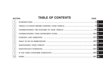
- Download PDF Manual
-
⬙Setup Select Phone.⬙
• Press the ’Phone’ button to begin. • After the ⬙Ready⬙ prompt and the following beep, say • The phone names (along with priority numbers) will • When prompted say the priority number of the cellu- lar phone you wish to select. You can also press the ⬘Voice Recognition’ button anytime while the list is being played and say the priority number. • The selected phone will be used for the next phone call. If the selected phone is not available, the UCon- nect™ system will return to using the highest priority phone present in or near (approximately with in 30
feet) the vehicle.⬙Setup Phone Pairing.⬙
Delete UConnect™ Paired Cellular Phones • Press the ’Phone’ button to begin. • After the ⬙Ready⬙ prompt and the following beep, say • At the next prompt, say ⬙Delete.⬙ • The phone names (along with priority numbers) will • When prompted say the priority number of the cellu- lar phone (or “All” to delete all phones) you wish to delete. You can also press the ⬘Voice Recognition’ button anytime while the list is being played and say the priority number.
be played.
UNDERSTANDING THE FEATURES OF YOUR VEHICLE 107
Things You Should Know About Your UConnect™ System
Voice Recognition (VR) • Always wait for the beep before speaking. • Speak normally, without pausing, just as you would speak to a person sitting approximately eight (8) feet away from you. • Make sure that no one other than you is speaking during a voice recognition period. • Performance is maximized under: • low-to-medium blower setting, • low-to-medium vehicle speed, • low road noise, • smooth road surface,
108 UNDERSTANDING THE FEATURES OF YOUR VEHICLE
• fully closed windows, • dry weather condition. • Even though the system is designed for users speaking in North American English, French, and Spanish ac- cents, the system may not always work for some. • When navigating through an automated system, such as, voice mail, or when sending a page, at the end of speaking the digit string, make sure to say ⬙send.⬙ • Storing names in phonebook when vehicle is not in • It is not recommended to store similar sounding • UConnect™ phonebook name tag recognition rate is optimized for the voice of the person who stored the name in the phonebook.
names in the UConnect™ phonebook.
motion is recommended.
spoken ⬙eight-zero-zero.⬙
• You can say ⬙O⬙ (letter ⬙O⬙) for ⬙0⬙ (zero). ⬙800⬙ must be • Even though international dialing for most number combinations is supported, some shortcut dialing number combinations may not be supported.
Far End Audio Performance • Audio quality is maximized under: • low-to-medium blower setting, • low-to-medium vehicle speed, • low road noise, • smooth road surface, • fully closed windows, and • dry weather condition. • Operation from driver seat.
• Performance, such as, audio clarity, echo. and loud- ness to a large degree, rely on the phone and network, and not the UConnect™ system. • Echo at far end can sometime be reduced by lowering
the in-vehicle audio volume.
Bluetooth Communication Link Cellular phones have been found to occasionally lose connection to the UConnect™ system. When this hap- pens, the connection can generally be re-established by switching the phone off/on. Your cell phone is recom- mended to remain in Bluetooth ⬙on⬙ mode.
UNDERSTANDING THE FEATURES OF YOUR VEHICLE 109
Power-Up After switching the ignition key from OFF to either ON or ACC position, or after a reset, you must wait at least five (5) seconds prior to using the system.
110 UNDERSTANDING THE FEATURES OF YOUR VEHICLE
UNDERSTANDING THE FEATURES OF YOUR VEHICLE 111
112 UNDERSTANDING THE FEATURES OF YOUR VEHICLE
Primary Zero Add location All Confirmation prompts Delete a name Language List names List paired phones Pager Phone pairing Phonebook Return to main menu Select phone Set up
North American English Alternate(s) Oh Add new All of them Confirmations prompts Delete Select language List all List phones Beeper Pairing Phone book Return. Main menu select Phone settings phone set up
UNDERSTANDING THE FEATURES OF YOUR VEHICLE 113
SEATS The seating options available in this truck are the result of extensive customer research and evaluations.
WARNING!
It is extremely dangerous to ride in a cargo area, inside or outside of a vehicle. In a collision, people riding in these areas are more likely to be seriously injured or killed. Do not allow people to ride in any area of your vehicle that is not equipped with seats and seat belts. Be sure everyone in your vehicle is in a seat and using a seat belt properly.
114 UNDERSTANDING THE FEATURES OF YOUR VEHICLE
40-20-40 Front Seat
As the name implies, the seat is divided into 3 segments. The outboard seat portions are each 40% of the total width of the seat. The back of the center portion (20%) easily folds down to provide an armrest/center storage compartment (if equipped).
Each outboard seat is independently adjustable forward or backward and is equipped with a back recliner. The manual seat adjustment handle is found at the front edge of each seat cushion. Pull up on the handle and slide the seat to get the most comfortable position.
WARNING!
Adjusting a seat while the vehicle is moving is dangerous. The sudden movement of the seat could cause you to lose control. The seat belt might not be properly adjusted and you could be injured. Adjust any seat only while the vehicle is parked.
Reclining Seats The recliner handle is on the outside of the seat cushion. Pull up on the handle to release the seat back and adjust for comfort.
UNDERSTANDING THE FEATURES OF YOUR VEHICLE 115
WARNING!
You can be seriously, even fatally injured riding in a seat with the seatback reclined. Do not ride with the seatback reclined so that the shoulder belt is no longer resting against your chest. If you ride in this position, the shoulder harness will no longer be restraining you. In a collision you could slide under the seat belt and receive serious or fatal injuries. Recline in a seat only when the vehicle is parked.
Adjustable Head Restraints Head restraints can reduce the risk of whiplash injury in the event of impact from the rear. Pull up or push down on the restraints so that the upper edge is as high as practical, at least to the level of the ears.
116 UNDERSTANDING THE FEATURES OF YOUR VEHICLE
To lower the head restraint, push in the button and then push down on the head restraint.
Manual Rotary Lumbar Support Adjustment — If Equipped Rotating the lumbar control knob on the left side of the driver’s seatback and on the right side of the passenger’s seatback increases or decreases the lumbar support.
Manual Lumbar Adjustment
Power Seats — If Equipped
CAUTION!
Don’t put anything under a power seat. It may cause damage to the seat controls.
UNDERSTANDING THE FEATURES OF YOUR VEHICLE 117
Up, Down, Forward, and Rearward
The power seat controls are on the outboard side of the front seat cushions. Three switches control the seat move- ment. The four-way switch in the center can be moved forward or backwards to get the most comfortable posi- tion. The same switch can be moved up and down to
118 UNDERSTANDING THE FEATURES OF YOUR VEHICLE
control seat height. Change the seat angle by using the two toggle switches, tilting it up or down.
Heated Seats — If Equipped The heated seat switches are located in the instrument panel under the climate controls.
Tilt Adjustment
Heated Seat Switches
Each heated seat switch has two settings (HI and LOW). Press the switch once to obtain High heat level, then press the switch again to obtain Low heat level. Pressing
the switch a third time will turn the heated seats OFF. If you do not purposefully turn the switch OFF, the seat heating level will automatically change to the next lower level, or OFF. The High heat level operates for 45 minutes (approximate), the Low heat level operates for 60 min- utes (approximate). The seat heat will also turn OFF when the ignition is turned OFF. Both of the indicators ON identifies High heat level. The lower indicator On only, identifies Low heat level. Flashing indicator lights on the switch indicate that the Heated Seat System needs servicing.
UNDERSTANDING THE FEATURES OF YOUR VEHICLE 119
TO OPEN AND CLOSE THE HOOD
Hood Release Lever
To open the hood, two latches must be released. First pull the hood release lever located below the steering wheel at the base of the instrument panel. Once the hood is
120 UNDERSTANDING THE FEATURES OF YOUR VEHICLE
released you must reach into the opening beneath the center of the grille and push up the latch to release the safety catch before raising the hood. To prevent possible damage, do not slam the hood to close it. Use a firm downward push at the front center of the hood to ensure that both latches engage.
WARNING!
If the hood is not fully latched, it could fly up when the vehicle is moving and block your forward vision. Be sure all hood latches are latched fully before driving.
Secondary Latch
LIGHTS
Interior Lights
UNDERSTANDING THE FEATURES OF YOUR VEHICLE 121
Headlight Switch Location
Dimmer Control
Courtesy and dome lights are turned on when the front doors are opened, when the dimmer control (rotating wheel on the right side of the switch) is rotated to the upward detent position, or if equipped, when the UN- LOCK button is pressed on the key fob.When a door is
122 UNDERSTANDING THE FEATURES OF YOUR VEHICLE
open and the interior lights are on, rotating the dimmer control all the way down to the OFF detent will cause all the interior lights to go out. This is also known as the ⬙Party⬙ mode because it allows the doors to stay open for extended periods of time without discharging the vehi- cle’s battery. The brightness of the instrument panel lighting can be regulated by rotating the dimmer control up (brighter) or down (dimmer). When the headlights are ON you can supplement the brightness of the odometer, trip odom- eter, radio and overhead console by rotating the control up until you hear a click. This feature is termed the “Parade” mode and is useful when headlights are re- quired during the day. Club Cab/Quad Cab models may have an optional switched dome lamp that may be operated by pressing the lens.
Battery Saver To protect the life of your vehicle’s battery, Load Shed- ding is provided for both the interior and exterior lights. If the ignition is off and any door is left ajar for 10
minutes or the dimmer control is rotated upwards for 10
minutes, the interior lights will automatically turn off. If the headlamps remain on while the ignition is cycled off, the exterior lights will automatically turn off after 8
minutes. If the headlamps are turned on and left on for 8
minutes while the ignition is off, the exterior lights will automatically turn off. NOTE: Battery Saver mode is cancelled if the ignition is ON.Headlamp Delay To aid in your exit, your vehicle is equipped with a headlamp delay that will leave the headlamps on for 90
seconds. This delay is initiated when the ignition is turned OFF while the headlamp switch is on, and then the headlamp switch is cycled off. Headlamp delay can be cancelled by either turning the headlamp switch ON then OFF or by turning the ignition ON. Headlights, Parking Lights, Panel LightsWhen the headlight switch is rotated to the first position, the parking lights, taillights, side marker lights, license plate light and instrument panel lights are all turned on. The headlights will turn ON when the switch is rotated to the second position.
UNDERSTANDING THE FEATURES OF YOUR VEHICLE 123
Light Switch Rotation
Your vehicle is equipped with plastic headlight lenses that are lighter and less susceptible to stone breakage than glass headlights. Plastic is not as scratch resistant as glass and therefore different lens cleaning procedures must be followed.
124 UNDERSTANDING THE FEATURES OF YOUR VEHICLE
To minimize the possibility of scratching the lenses and reducing light output, avoid wiping with a dry cloth. To remove road dirt, wash with a mild soap solution fol- lowed by rinsing. Do not use abrasive cleaning components, solvents, steel wool or other abrasive materials to clean the lenses. Daytime Running Lights (Canada Only and Fleet Vehicles) The headlights on your vehicle will illuminate when the engine is started. This provides a constant ⬙Lights ON⬙ condition until the ignition is turned OFF. The lights illuminate at less than 50% of normal intensity. If the parking brake is applied the Daytime Running Lights will turn off.
Lights-on Reminder If the headlights, parking lights, or cargo lights are left on, after the ignition is turned off, a chime will sound when the driver’s door is opened. Fog Lights — If Equipped
The foglights are turned ON by placing the head- light rotary control in the parking light or head- light position and pushing in the headlight rotary control. The fog lights will operate only when the parking lights are ON or when the vehicle headlights are ON low beam. An indicator light located in the instrument cluster will illuminate when the fog lights are on. The fog lights will turn off when the switch is pushed a second time, when the headlight switch is rotated to the OFF position, or the high beam is selected.
CARGO Light — If Equipped
Cargo Light Switch
The cargo lights are turned on by pressing on the CARGO button. The interior lights will also turn on when the cargo lights are on. The cargo lights will also turn on for 30 seconds when a key fob Unlock is pressed, as part of the illuminated entry feature.
UNDERSTANDING THE FEATURES OF YOUR VEHICLE 125
MULTIFUNCTION CONTROL LEVER The multifunction control lever is located on the left side of the steering column. Turn Signals Move the lever up or down to signal a right-hand or left-hand turn. The arrow on either side of the instrument cluster flashes to indicate the direction of the turn, and proper operation of the front and rear turn signal lights. If a defective bulb or wiring circuit is detected for the turn signal system, the arrow indicators will flash at a faster rate. If an indicator fails to light when the lever is moved, it would suggest that the switch or indicator lamp is defective.
126 UNDERSTANDING THE FEATURES OF YOUR VEHICLE
You can signal a lane change by moving the lever partially up or down.
Passing Light You can signal another vehicle with your headlights by partially pulling the multifunction lever toward the steer- ing wheel. This will cause the high beam headlights to turn on until the lever is released.
Turn Signal Lever
High Beam / Low Beam Select Switch Pull the multifunction control lever fully toward the steering wheel to switch the headlights from HIGH or LOW beam.
UNDERSTANDING THE FEATURES OF YOUR VEHICLE 127
Windshield Wipers
High Beam / Low Beam
Windshield Wiper / Washer Switch
The wipers and washers are operated by a switch in the multifunction control lever. Turn the end of the handle to select the desired wiper speed.
128 UNDERSTANDING THE FEATURES OF YOUR VEHICLE
Intermittent Wiper System The intermittent feature of this system was designed for use when weather conditions make a single wiping cycle, with a variable pause between cycles, desirable. For maximum delay between cycles, rotate the control knob into the upper end of the delay range. The delay interval decreases as you rotate the knob until it enters the LO continual speed position. The delay can be regulated from a maximum of about 15 seconds between cycles, to a cycle every 2 seconds. The delay intervals will double in duration when the vehicle speed is 10 mph (16 km) or less.
WARNING!
Sudden loss of visibility through the windshield could lead to an accident. You might not see other vehicles or other obstacles. To avoid sudden icing of the windshield during freezing weather, warm the windshield with defroster before and during wind- shield washer use.
Windshield Washers To use the washer, push in on the washer knob on the end of the multifunction control lever and hold while spray is desired. If the washer knob is depressed while in the delay range, the wiper will operate for several seconds after the washer knob is released. It will then resume the intermittent interval previously selected. If the washer knob is pushed, for a period greater than 1 second, while in the OFF position, the wiper will wipe approximately three wipes, after the wash knob is released.
To prevent freeze-up of your windshield washer system in cold weather, select a solution or mixture that meets or exceeds the temperature range of your climate. This rating information can be found on most washer fluid containers.
TILT STEERING COLUMN To tilt the column, pull rearward on the lever below the turn signal control and move the wheel up or down, as desired. Push the lever forward to lock the column firmly in place.
UNDERSTANDING THE FEATURES OF YOUR VEHICLE 129
Tilt Steering Control Lever
130 UNDERSTANDING THE FEATURES OF YOUR VEHICLE
WARNING!
Tilting the steering column while the vehicle is moving is dangerous. Without a stable steering col- umn, you could lose control of the vehicle and have an accident. Adjust the column only while the ve- hicle is stopped. Be sure it is locked before driving.
ELECTRONIC SPEED CONTROL — IF EQUIPPED When engaged, this device takes over accelerator opera- tion at speeds greater than (refer to the table below for the speed for your specific engine). The controls are mounted on the steering wheel.
To Activate Push the ON/OFF button to the ON position. In the instrument cluster, the word “CRUISE” illuminates when the system is on.
To Set At A Desired Speed When the vehicle has reached the desired speed, press and release the SET button. Release the accelerator and the vehicle will operate at the selected speed. To Deactivate A soft tap on the brake pedal, normal braking, clutch pressure while slowing the vehicle, or pressing the CAN- CEL button will deactivate speed control without erasing the memory. Pushing the ON/OFF button to the OFF position or turning off the ignition erases the memory.
UNDERSTANDING THE FEATURES OF YOUR VEHICLE 131
WARNING!
Leaving the Speed Control ON when not in use is dangerous. You could accidentally set the system to cause it to go faster than you want. You could lose control and have an accident. Always leave the system OFF when you aren’t using it.
To Resume Speed To resume a previously set speed, push and release the RESUME button. Resume can be used at any speed above (refer to the table below for the speed for your specific engine). To Vary The Speed Setting When the speed control is on, speed can be increased by pressing and holding the ACCEL button. When the button is released, a new set speed will be established.
132 UNDERSTANDING THE FEATURES OF YOUR VEHICLE
Tapping the ACCEL button once will result in a speed increase (refer to the table below for the speed for your specific engine). Each time the button is tapped, speed increases so that tapping the button three times will increase speed by three increments. Tapping the DECEL button once will result in a speed decrease (refer to the table below for the speed for your specific engine). Each time the button is tapped, speed Functions Engage Speed Minimun RESUME Speed ACCEL Increase DECEL Decrease Dropout Speed
will decrease. For example, tapping the button 3 times will decrease the speed by 3 times the speed listed in the table below (refer to the table below for the speed for your specific engine). To decrease speed while the speed control is on, press and hold the DECEL button. Release the button when the desired speed is reached, and the new speed will be set.
5.7L Engine 25 mph (40 km/h) 20 mph (32 km/h) 1 mph (2 km/h) 1 mph (2 km/h) 20 mph (32 km/h)
To Accelerate For Passing Depress the accelerator as you would normally. When the pedal is released, the vehicle will return to the set speed. NOTE: When driving uphill, at elevations above 2,000
feet (610 meters), or when the vehicle is heavily loaded (especially when towing) the vehicle may slow below the SET speed. If the vehicle speed drops below (refer to the table below for the speed for your specific engine), the speed control will automatically disengage. If this hap- pens, you can push down on the accelerator pedal to maintain the desired speed. Vehicles equipped with a 5–speed-manual transmission should be operated in 4th gear or lower under the above conditions. Vehicles equipped with a Automatic transmission may exhibit several downshifts under the above conditions.UNDERSTANDING THE FEATURES OF YOUR VEHICLE 133
To reduce the frequency of the downshifts and to im- prove vehicle performance, it is advisable to lock out overdrive by pressing the “TOW/HAUL” button located at the end of the gear shifter.
WARNING!
Speed Control can be dangerous where the system can’t maintain a constant speed. Your vehicle could go too fast for the conditions, and you could lose control. An accident could be the result. Don’t use Speed Control in heavy traffic or on roads that are winding, icy, snow-covered, or slippery.
134 UNDERSTANDING THE FEATURES OF YOUR VEHICLE
OVERHEAD CONSOLE— IF EQUIPPED The two optional overhead consoles may consist of the following features:
Overhead Console Features
• Courtesy/Reading Lights • Compass/Temperature Mini-Trip Computer (CMTC)
— If Equipped
• Universal Garage Door Opener — If Equipped Courtesy/Reading Lights In the middle of the console are two courtesy/reading lights. Both lights illuminate as courtesy lights when a door is opened, when the dimmer control is rotated to the courtesy light position (fully upward position), or when the UNLOCK button is pressed on the Remote Keyless Entry transmitter, if so equipped. These lights are also operated individually as reading lights by pressing the recessed area of the corresponding lens. NOTE: The courtesy/reading lights will remain on until the switch is pressed a second time, so be sure they have been turned off before leaving the vehicle. If the interior lights are left on after the vehicle is turned off, they will extinguish after 15 minutes.
OVERHEAD CONSOLE WITH COMPASS/TEMPERATURE MINI-TRIP COMPUTER — IF EQUIPPED This optional overhead console consists of the following: • Courtesy Lights • Compass/Temperature Mini-Trip Computer (CMTC)
UNDERSTANDING THE FEATURES OF YOUR VEHICLE 135
This overhead console allows you to choose between a compass/temperature display and one of four trip con- ditions being monitored. US/M Button
Use this button to change the display from U.S. to metric measurement units.
136 UNDERSTANDING THE FEATURES OF YOUR VEHICLE
RESET Button
Global Reset If the RESET button is pressed twice within 2 seconds while in any of the 3 resettable displays (AVG ECO, ODO, ET), the Global Reset will reset all 3 displays. Step Button
Use this button to reset the following displays: Average Fuel Economy (AVG ECO) Trip Odometer (ODO) Elapsed time (ET)
Use this button to choose or cycle through the four trip conditions.
Average Fuel Economy (AVG ECO) Shows the average fuel economy since the last reset. Average fuel economy is a running average of the amount of fuel used and the distance the vehicle has traveled. When the fuel economy is reset, the display will momen- tarily blank. Then, the history information will be erased, and the averaging will continue from where it was before the reset. Distance To Empty (DTE) Shows the estimated distance that can be traveled with the fuel remaining in the tank. This estimated distance is determined by weighted average of the instantaneous and average fuel economy, according to the current fuel tank level. This is not resettable NOTE: Significant changes in driving style or vehicle loading will greatly affect the actual drivable distance of the vehicle, regardless of the DTE displayed value.
UNDERSTANDING THE FEATURES OF YOUR VEHICLE 137
When the DTE value is less than 30 miles estimated driving distance, the DTE display will change to an alternating test display of “LO” and “FUEL”. This dis- play will continue until the vehicle runs out of fuel. Adding a significant amount of fuel to the vehicle will turn off the “LO FUEL” text and a new DTE value will be displayed, based on the current values in the DTE calculation and the current fuel tank level. It is possible for DTE to display “LO FUEL” NOTE: before the low fuel warning light turns on in the instru- ment cluster. This could occur because low fuel warning is set to a specified fuel tank volume and DTE is an estimated distance calculation based on fuel economy and remaining fuel tank volume. Ram fuel tank volumes are as follows: • 34 gallons - short box models • 35 gallons - long box models
138 UNDERSTANDING THE FEATURES OF YOUR VEHICLE
Trip Odometer (ODO) This display shows the distance traveled since the last reset. Resetting of this screen will cause the trip odometer to change to Zero. Elapsed Time (ET) This display shows the accumulated ignition ON time since the last reset. Resetting the Elapsed Time will cause the display to change to Zero.
C/T Button
Use this button to select a readout of the outside tem- perature and one of eight compass headings that indicate the direction in which the vehicle is facing.
WARNING!
Manual Compass Calibration
UNDERSTANDING THE FEATURES OF YOUR VEHICLE 139
Even if the display still reads a few degrees above 32°F ( 0°C), the road surface may be icy, particularly in woods or on bridges. Drive carefully under such conditions to prevent an accident and possible per- sonal injury or property damage.
Automatic Compass Calibration This compass is self-calibrating which eliminates the need to manually set the compass. When the vehicle is new, the compass may appear erratic and the CAL symbol will be displayed. After completing up to three 360° turns, with the vehicle traveling less than 5 mph (8 km/h), in an area free from large metal or metallic objects, the CAL symbol will turn off and the compass will function normally.
NOTE: To ensure proper compass calibration, make sure the compass variance is properly set before manu- ally calibrating the compass. If the compass appears erratic and the CAL symbol does not appear, you must manually put the compass into the “Calibration” mode. Recalibrating The Compass Turn on the ignition and set the display to “Compass/ Temperature.” Press and hold the RESET button to change the display between VAR (compass variance) and CAL (compass calibration) modes. When the CAL sym- bol is displayed complete one 360° turn in an area free from large metal objects or power lines. The CAL symbol will turn off and the compass will function normally.
140 UNDERSTANDING THE FEATURES OF YOUR VEHICLE
Compass Variance is the difference between magnetic north and geographic north. In some areas of the country, the difference between magnetic and geographic north is great enough to cause the compass to give false readings. If this occurs, the compass variance must be set according to the Compass Variance Map.
NOTE: The default for the compass variance is zone 8. To set the variance: Turn the ignition ON and set the display to “Compass/Temperature.” Press and hold the RESET button approximately five seconds. The last vari- ance zone number will be displayed. Press the STEP button to select the new variance zone and press the RESET button to resume normal operation.
UNDERSTANDING THE FEATURES OF YOUR VEHICLE 141
Outside Temperature Because the ambient temperature sensor is located un- derhood, engine temperature can influence the displayed temperature, therefore, temperature readings are slowly updated when the vehicle speed is below 20 mph (30
km/h) or during stop and go driving.142 UNDERSTANDING THE FEATURES OF YOUR VEHICLE
GARAGE DOOR OPENER — IF EQUIPPED The HomeLink威 Universal Transceiver replaces up to three remote controls (hand held transmitters) that oper- ate devices such as garage door openers, motorized gates, or home lighting. It triggers these devices at the push of a button. The Universal Transceiver operates off your vehicle’s battery and charging system; no batteries are needed.
HomeLink威 Programming Buttons
For additional information on HomeLink威, call 1–800– 355–3515, or on the internet at www.homelink.com.
WARNING!
Programming HomeLink
UNDERSTANDING THE FEATURES OF YOUR VEHICLE 143
A moving garage door can cause injury to people and pets in the path of the door. People or pets could be seriously or fatally injured. Only use this transceiver with a garage door opener that has a “stop and reverse” feature as required by federal safety stan- dards. This includes most garage door opener mod- els manufactured after 1982. Do not use a garage door opener without these safety features it could cause injury or death. Call toll-free 1–800–355–3515
or, on the Internet at www.homelink.com for safety information or assistance.NOTE: When programming a garage door opener, it is advised to park outside the garage. It is also recom- mended that a new battery be placed in the hand-held transmitter of the device being programmed to HomeLink for quicker training and accurate transmis- sion of the radio-frequency signal. 1. Press and hold the two outer HomeLink buttons, and release only when the indicator light begins to flash (after 20 seconds). Do not hold the buttons for longer than 30
seconds and do not repeat step one to program a second and/or third hand-held transmitter to the remaining two HomeLink buttons.144 UNDERSTANDING THE FEATURES OF YOUR VEHICLE
WARNING!
Vehicle exhaust contains carbon monoxide, a danger- ous gas. Do not run the vehicle’s exhaust while training the transceiver. Exhaust gas can cause seri- ous injury or death.
WARNING!
Your motorized door or gate will open and close while you are training the Universal Transceiver. Do not train the transceiver if people or pets are in the path of the door or gate. A moving door or gate can cause serious injury or death to people and pets or damage to objects.
Outer HomeLink buttons
2. Position the end of your hand-held transmitter 1-3
inches (3-8 cm) away from the HomeLink buttons while keeping the indicator light in view. 3. Simultaneously press and hold both the HomeLink button that you want to train and the hand-held trans- mitter buttons. Do not release the buttons until step 4
has been completed. NOTE: Some gate operators and garage door openers may require you to replace this Programming Step 3 with procedures noted in the ⬙Gate Operator/Canadian Pro- gramming⬙ section. 4. The HomeLink indicator light will flash slowly and then rapidly after HomeLink successfully receives the frequency signal from the hand-held transmitter. Release both buttons after the indicator light changes from the slow to the rapid flash.UNDERSTANDING THE FEATURES OF YOUR VEHICLE 145
5. Press and hold the just trained HomeLink button and observe the indicator light. If the indicator light stays on constantly, programming is complete and your device should activate when the HomeLink button is pressed and released. NOTE: To program the remaining two HomeLink but- tons, begin with ⬙Programming⬙ step two. Do not repeat step one. If the indicator light blinks rapidly for two seconds and then turns to a constant light, continue with ⴖProgram- mingⴖ steps 6-8 to complete the programming of a rolling code equipped device (most commonly a garage door opener). 6. At the garage door opener receiver (motor-head unit) in the garage, locate the ⬙learn⬙ or ⬙smart⬙ button. This can usually be found where the hanging antenna wire is attached to the motor-head unit.
146 UNDERSTANDING THE FEATURES OF YOUR VEHICLE
7. Firmly press and release the ⬙learn⬙ or ⬙smart⬙ button. (The name and color of the button may vary by manu- facturer.) NOTE: There are 30 seconds in which to initiate step eight. 8. Return to the vehicle and firmly press, hold for two seconds and release the programmed HomeLink button. Repeat the ⴖpress/hold/releaseⴖ sequence a second time, and, depending on the brand of the garage door opener (or other rolling code equipped device), repeat this sequence a third time to complete the programming. HomeLink should now activate your equipped device. NOTE: To program the remaining two HomeLink but- tons, begin with ⬙Programming⬙ step two. Do not repeat step one. For questions or comments, please contact HomeLink at www.homelink.com or 1-800-355-3515.
rolling code
Canadian Programming/Gate Programming Canadian radio-frequency laws require transmitter sig- nals to ⬙time-out⬙ (or quit) after several seconds of transmission which may not be long enough for HomeLink to pick up the signal during programming. Similar to this Canadian law, some U.S. gate operators are designed to ⬙time-out⬙ in the same manner. If you live in Canada or you are having difficulties programming a gate operator by using the ⬙Program- ming⬙ procedures (regardless of where you live), replace ⴖProgramming HomeLinkⴖ step 3 with the following: If programming a garage door opener or gate NOTE: operator, it is advised to unplug the device during the ⬙cycling⬙ process to prevent possible overheating. 3. Continue to press and hold the HomeLink button while you press and release every two seconds (⬙cycle⬙) your hand-held transmitter until the frequency signal has
successfully been accepted by HomeLink. (The indicator light will flash slowly and then rapidly.) Proceed with ⬙Programming⬙ step four to complete. Using HomeLink To operate, simply press and release the programmed HomeLink button. Activation will now occur for the trained device (i.e. garage door opener, gate operator, security system, entry door lock, home/office lighting, etc.). For convenience, the hand-held transmitter of the device may also be used at any time. In the event that there are still programming difficulties or questions, contact HomeLink at: www.homelink.com or 1-800-355- 3515. Erasing HomeLink Buttons To erase programming from the three buttons (individual buttons cannot be erased but can be ⬙reprogrammed⬙ - note below), follow the step noted:
UNDERSTANDING THE FEATURES OF YOUR VEHICLE 147
• Press and hold the two outer HomeLink buttons until the indicator light begins to flash-after 20 seconds. Release both buttons. Do not hold for longer that 30
seconds. HomeLink is now in the train (or learning) mode and can be programmed at any time beginning with ⬙Programming⬙ - step 2.Reprogramming a Single HomeLink Button To program a device to HomeLink using a HomeLink button previously trained, follow these steps: 1. Press and hold the desired HomeLink button. DO NOT release the button. 2. The indicator light will begin to flash after 20 seconds. Without releasing the HomeLink button, proceed with ⬙Programming⬙ step 2
For questions or comments, contact HomeLink at: www.homelink.com or 1-800-355-3515.148 UNDERSTANDING THE FEATURES OF YOUR VEHICLE
Security If you sell your vehicle, be sure to erase the frequencies. To erase all of the previously trained frequencies, hold down both outside buttons until the green light begins to flash. This device complies with part 15 of FCC rules and with RSS-210 of Industry Canada. Operation is subject to the following conditions: • This device may not cause harmful interference. • This device must accept any interference that may be received including interference that may cause undes- ired operation.
NOTE: Changes or modifications not expressly ap- proved by the party responsible for compliance could void the user’s authority to operate the equipment. HomeLink威 is a trademark owned by Johnson Controls, Inc.
POWER SUNROOF — IF EQUIPPED The power sunroof switch is located between the sun visors on the overhead console.
WARNING!
• Never leave children in a vehicle, with the keys in the ignition switch. Occupants, particularly unat- tended children, can become entrapped by the power sunroof while operating the power sunroof switch. Such entrapment may result in serious injury or death. • In an accident, there is a greater risk of being thrown from a vehicle with an open sunroof. You could also be seriously injured or killed. Always fasten your seat belt properly and make sure all passengers are properly secured too. • Do not allow small children to operate the sun- roof. Never allow fingers or other body parts, or any object to project through the sunroof opening. Injury may result.
UNDERSTANDING THE FEATURES OF YOUR VEHICLE 149
Open Sunroof - Express Mode Momentarily pressing the switch rearward will activate the Express Open Feature, causing the sunroof to open automatically. During the Express Open operation, any movement of the switch will stop the sunroof and it will remain in a partial open position. Again, momentarily pressing the switch rearward will activate the Express Open Feature. Comfort Stop
The sunroof is equipped with an intermediate “Comfort Stop” position. This is the first stop that express open reaches. This is designed to reduce wind buffeting at vehicle speeds between 20 - 40 mph (32 - 64 km/h). Pressing the switch momentarily rearward again will open the sunroof to its full open position however wind buffeting can occur at full open.
150 UNDERSTANDING THE FEATURES OF YOUR VEHICLE
Closing Sunroof - Express Press the switch forward and release, and the sunroof will close automatically from any position. The sunroof will close fully and stop automatically. This is called Express Close. During Express Close operation, any movement of the switch will stop the sunroof. Pinch Protect Feature This feature will detect an obstruction in the opening of the sunroof during Express Close operation. If an ob- struction in the path of the sunroof is detected, the sunroof will automatically retract. Remove the obstruc- tion if this occurs. Next, press the switch forward and release to Express Close. Pinch Protect Override If a known obstruction (ice, debris, etc.) prevents closing, press the switch forward and hold for two seconds after the reversal occurs. This allows the sunroof to move towards the closed position.
NOTE: Pinch protection is disabled while the switch is pressed. Venting Sunroof - Express Press and release the ⬙V⬙ button, and the sunroof will open to the vent position. This is called Express Vent, and will occur regardless of sunroof position. During Express Vent operation, any movement of the switch will stop the sunroof. Sunshade Operation The sunshade can be opened manually. However, the sunshade will open automatically as the sunroof opens. NOTE: The sunshade cannot be closed if the sunroof is open.
Wind Buffeting Wind buffeting can be described as the perception of pressure on the ears or a helicopter type sound in the ears. Your vehicle may exhibit wind buffeting with the windows down, or the sunroof (if equipped) in certain open or partially open positions. This is a normal occur- rence and can be minimized. If the buffeting occurs with the rear windows open, open the front and rear windows together to minimize the buffeting. If the buffeting occurs with the sunroof open, adjust the sunroof opening to minimize the buffeting or open any window. Sunroof Maintenance Use only a non-abrasive cleaner and a soft cloth to clean the glass panel. Sunroof Fully Closed Press the switch forward and release to ensure that the sunroof is fully closed.
UNDERSTANDING THE FEATURES OF YOUR VEHICLE 151
ELECTRICAL POWER OUTLETS The auxiliary electrical outlet can provide power for in cab accessories designed for use with the standard “cigar lighter” plug. The outlet is located in the instrument panel below and to the right of the Climate Control Panel. A cap is attached to the outlet base indicating “Power Outlet” 12V-20A. There is an additional Power Outlet in the center console of a 40/20/40 seat (if equipped). The outlet(s) has/have a fused direct feed from the battery so it/they receive power whether the ignition is ON or OFF. All accessories connected to this/these outlet(s) should be removed or turned OFF when the vehicle is not in use to protect the battery against discharge. If desired, all of the power outlets can be NOTE: converted by your authorized dealer to provide power with the ignition switch in the ON position only.
CIGAR LIGHTER AND ASH RECEIVER The removable ash receiver is located in the instrument panel cup holder tray. The cigar lighter is located on the instrument panel, above and to the left of the ash receiver.
152 UNDERSTANDING THE FEATURES OF YOUR VEHICLE
CAUTION!
Electrical Outlet Use With Engine Off • Many accessories that can be plugged in draw power from the vehicle’s battery, even when not in use (i.e. cellular phones, etc.). Eventually, if plugged in long enough, the vehicle’s battery will discharge sufficiently to degrade battery life and/or prevent engine starting. • Accessories that draw higher power (i.e. coolers, vacuum cleaners, lights, etc.), will discharge the battery even more quickly. Only use these inter- mittently and with greater caution. • After the use of high power draw accessories, or long periods of the vehicle not being started (with accessories still plugged in), the vehicle must be driven a sufficient length of time to allow the generator to recharge the vehicle’s battery.
As a child safety precaution, the lighter only operates with the ignition switch ON. It heats when pushed in and pops out automatically when ready for use. To preserve the heating element, do not hold the lighter in the heating position.
UNDERSTANDING THE FEATURES OF YOUR VEHICLE 153
CUPHOLDERS
Front Instrument Panel Cupholders To secure the cup, place the cup to be held into one of the cup wells and then push the cupholder arm toward the cup until it is held stable.
154 UNDERSTANDING THE FEATURES OF YOUR VEHICLE
Rear Cupholder — Quad Cab — If Equipped Quad Cab vehicles may be equipped with a rear cup- holder that consists of two cupwells for rear passenger convenience.
STORAGE
Center Storage Compartment — If Equipped
The center portion of the seat folds down to provide an armrest with unique storage compartments under the lid. Push the button on the front of the armrest to raise the cover. Inside there is a power outlet (if equipped), removable coin holder (if equipped), and two dividers to configure the storage area into compartments. For ex- ample, compartments can be configured to hold a lap-top computer, a cellular telephone, CD’s and miscellaneous items. The top of the cover provides a generous firm surface to serve as a desktop for your “mobile office.”
WARNING!
• This armrest is not a seat. Anyone seated on the armrest could be seriously injured during vehicle operation, or an accident. Only use the center seating position when the armrest is fully upright. • In an accident, the latch may open if the total weight of the items stored exceeds about 10 lbs (4.5 kg). These items could be thrown about endangering occupants of Items stored should not exceed a total of 10 lbs (4.5 kg).
the vehicle.
Storage and Seats — If Equipped Located in the center of the front 40/20/40 seat cushion there is a storage compartment. Standard cab models also have storage behind the seat.
UNDERSTANDING THE FEATURES OF YOUR VEHICLE 155
The Quad Cab models provide additional storage under the rear seat. Lift the seat to access the storage compart- ment.
Quad Cab Storage
156 UNDERSTANDING THE FEATURES OF YOUR VEHICLE
FOLD FLAT LOAD FLOOR — IF EQUIPPED
Fold Flat Load Floor — If Equipped Quad Cab models with a 60/40 rear seat, may be equipped with a folding load floor.
WARNING!
Do not operate the vehicle with loose items stored on the load floor. While driving or in an accident you may experience, abrupt stopping, rapid acceleration, or sharp turns. Loose objects stored on the load floor may move around with force and strike occupants, resulting in serious or fatal injury.
Unfolding the Load Floor 1. Lift the 60/40 seat cushion(s) to the upward position.
Quad Cab Rear 60/40 Seat
UNDERSTANDING THE FEATURES OF YOUR VEHICLE 157
Unfolding The Load Floor
2. Grasp the knob on the load floor and lift the knob until the load floor unfolds into position.
Load Floor In Open Position
3. Reverse the procedure to store the load floor.
158 UNDERSTANDING THE FEATURES OF YOUR VEHICLE
Positioning the Load Floor for Storage Access Under the Seat 1. Lift the 60/40 seat cushion(s) to the upward position. 2. Unsnap the securing snap located at either side of the load floor. 3. Lift the load floor up to access storage under the load floor.
WARNING!
Do not drive with the load floor in the up position. When stopping fast or in an accident, the load floor could move to the down position causing serious injury.
Load Floor Securing Straps
4. Reverse the procedure to put the load floor back in the secured down position before you operate the vehicle.
PICKUP BOX
Pickup Box Features
The pickup box on your new Ram has many features designed for utility and convenience.
UNDERSTANDING THE FEATURES OF YOUR VEHICLE 159
If you are installing a toolbox to the front of the NOTE: pickup box, you must use Mopar威 toolbox brackets available from your dealer. You can carry wide building materials (sheets of ply- wood, etc.) by building a raised load floor. Place lumber across the box in the indentations provided above the wheel housings and in the bulkhead dividers to form the floor.
WARNING!
The pickup box is intended for load carrying pur- poses only, not for passengers, who should sit in seats and use seat belts.
160 UNDERSTANDING THE FEATURES OF YOUR VEHICLE
WARNING!
• Care should always be exercised when operating a vehicle with unrestrained cargo. Vehicle speeds may need to be reduced. Severe turns or rough roads may cause shifting or bouncing of the cargo that may result in vehicle damage. If wide build- ing materials are to be frequently carried, the installation of a support is recommended. This will restrain the cargo and transfer the load to the pickup box floor. • If you wish to carry more than 600 lbs (272 kg) of material suspended above the wheelhouse, sup- ports must be installed to transfer the weight of the load to the pickup box floor or vehicle damage may result. The use of proper supports will permit loading up to the rated payload. • Unrestrained cargo may be thrown forward in an
accident causing serious or fatal injury.
There are stampings in the sheet metal on the inner side bulkheads of the box in front of and behind both wheel housings. Place wooden boards across the box from side to side to create separate load compartments in the pickup box. There are four tie-down cleats bolted to the lower sides of the pickup box that can sustain loads up to 1000 lbs (450
kg) total.SLIDE-IN CAMPERS DO NOT use slide-in campers on Power Wagon models.
UNDERSTANDING THE FEATURES OF YOUR VEHICLE 161
EASY-OFF TAILGATE The tailgate can be removed quickly. Tailgate removal is sometimes required for pickup box loading. To remove the tailgate unlatch the tailgate and remove the support cables by releasing the lock tang from the pivot, then rotate and pull away from the box. Once the cables are free, move to the right side of the tailgate hinge bracket. Raise the right side of the tailgate until the right side pivot clears the hanger bracket. Slide the entire tailgate to the right to free the left side pivot. Remove the tailgate from the vehicle entirely. Do not carry the tailgate loose in the truck pickup box. NOTE: Dual rear wheel pickup models require properly spaced rear clearance lights. If such a vehicle is operated without a tailgate, suitable lights must be installed.
162 UNDERSTANDING THE FEATURES OF YOUR VEHICLE
WARNING!
To avoid inhaling carbon monoxide, which is deadly, the exhaust system on vehicles equipped with “Cap or Slide-In Campers” should extend beyond the overhanging camper compartment and be free of leaks.
UNDERSTANDING YOUR INSTRUMENT PANEL
CONTENTS
䡵 Instruments And Controls . . . . . . . . . . . . . . . . . 166
䡵 Instrument Cluster . . . . . . . . . . . . . . . . . . . . . . 167
䡵 Instrument Cluster Description . . . . . . . . . . . . . 168
䡵 Electronic Digital Clock . . . . . . . . . . . . . . . . . . 176
▫ Clock Setting Procedure . . . . . . . . . . . . . . . . . 176䡵 Sales Code REF — AM/FM/CD (Single Disc)
Radio With Optional Hands Free Phone Capability . . . . . . . . . . . . . . . . . . . . . . . . . . . . 177
▫ Operating Instructions - Radio Mode . . . . . . . 177
▫ Operation Instructions - CD Mode . . . . . . . . . 180▫ Operating Instructions - Hands Free Phone
— If Equipped . . . . . . . . . . . . . . . . . . . . . . . 182
䡵 Sales Code RAQ – AM/FM/CD (6-Disc) Radio
With Optional Satellite Radio, Hands Free Phone, And Video Capabilities . . . . . . . . . . . . . . . . . . . 182
▫ Operating Instructions - Radio Mode . . . . . . . 183
▫ Operation Instructions - (CD Mode For CDAudio Play)
. . . . . . . . . . . . . . . . . . . . . . . . . 186
▫ Load/Eject Button (CD Mode For CD Audio
Play)
. . . . . . . . . . . . . . . . . . . . . . . . . . . . . . 188
. . . . . . . . . . . . . 190▫ Notes On Playing MP3 Files
164 UNDERSTANDING YOUR INSTRUMENT PANEL
▫ Operation Instructions - (CD Mode For MP3
Audio Play)
. . . . . . . . . . . . . . . . . . . . . . . . . 192
▫ Load/Eject Button (CD Mode For MP3 Play) . . 192䡵 Sales Code RAK – AM/FM/Cassette/CD (6-Disc) Radio With Optional Satellite Radio, Hands Free Phone, Video, MP3, And WMA Capabilities . . . . 195
▫ Operating Instructions - Radio Mode . . . . . . . 195
▫ Operating Instructions — Tape Player . . . . . . . 199
▫ Seek Button . . . . . . . . . . . . . . . . . . . . . . . . . 199
▫ Fast Forward (FF) . . . . . . . . . . . . . . . . . . . . . 200
▫ Rewind (RW) . . . . . . . . . . . . . . . . . . . . . . . . 200
▫ Tape Eject . . . . . . . . . . . . . . . . . . . . . . . . . . . 200
▫ Scan Button . . . . . . . . . . . . . . . . . . . . . . . . . 200
▫ Changing Tape Direction . . . . . . . . . . . . . . . . 200▫ Metal Tape Selection . . . . . . . . . . . . . . . . . . . 200
▫ Pinch Roller Release . . . . . . . . . . . . . . . . . . . 200
▫ Noise Reduction . . . . . . . . . . . . . . . . . . . . . . 201
▫ Operation Instructions - (CD Mode For CDAudio Play)
. . . . . . . . . . . . . . . . . . . . . . . . . 201
▫ Load/Eject Button (CD Mode For CD Audio
Play)
. . . . . . . . . . . . . . . . . . . . . . . . . . . . . . 202
. . . . . . . . . . . . . 204▫ Notes On Playing MP3 Files ▫ Operation Instructions - (CD Mode For MP3
And WMA Audio Play) . . . . . . . . . . . . . . . . . 206
▫ Load/Eject Button (CD Mode For MP3 And
WMA Play)
. . . . . . . . . . . . . . . . . . . . . . . . . 206
䡵 Sales Code REC — AM/FM/CD (6–Disc) Radio
With Navigation System . . . . . . . . . . . . . . . . . . 209
▫ Operating Instructions — Satellite Radio (If
Equipped)
. . . . . . . . . . . . . . . . . . . . . . . . . . 209
䡵 Remote Sound System Controls — If Equipped . . 210
▫ Radio Operation . . . . . . . . . . . . . . . . . . . . . . 210
▫ Tape Player . . . . . . . . . . . . . . . . . . . . . . . . . 211
▫ CD Player . . . . . . . . . . . . . . . . . . . . . . . . . . 211
䡵 Cassette Tape And Player Maintenance . . . . . . . 211
䡵 Compact Disc Maintenance . . . . . . . . . . . . . . . . 212
䡵 Radio Operation And Cellular Phones . . . . . . . . 213
䡵 Climate Controls . . . . . . . . . . . . . . . . . . . . . . . 213UNDERSTANDING YOUR INSTRUMENT PANEL 165
▫ Heater Only — Fleet Vehicles . . . . . . . . . . . . . 214
▫ Air Conditioning And Heating— If Equipped . . . . . . . . . . . . . . . . . . . . . . . 216
▫ Electric Rear Window Defroster And Heated
Sideview Mirrors — If Equipped . . . . . . . . . . 219
▫ Air Conditioning With Dual Zone Temperature
Control — If Equipped . . . . . . . . . . . . . . . . . 219
▫ Operating Tips . . . . . . . . . . . . . . . . . . . . . . . 224
▫ Operating Tips Chart . . . . . . . . . . . . . . . . . . . 226166 UNDERSTANDING YOUR INSTRUMENT PANEL
INSTRUMENTS AND CONTROLS
INSTRUMENT CLUSTER
UNDERSTANDING YOUR INSTRUMENT PANEL 167
168 UNDERSTANDING YOUR INSTRUMENT PANEL
INSTRUMENT CLUSTER DESCRIPTION
1. Check Gages
This light illuminates when the Voltmeter, Engine Oil Pressure or Engine Coolant Temperature gages indicate a reading either too high or too low. Examine the gages carefully, and follow the instructions above for each indicated problem. NOTE: When the ignition switch is turned to OFF, the Fuel Gage, Voltmeter, Oil Pressure and Engine Coolant Temperature gages may not show accurate readings. When the engine is not running, turn the ignition switch to ON to obtain accurate readings. 2. Voltage Gauge
When the engine is running, the gauge indicates the electrical system voltage. The pointer should stay within the normal range if the battery is charged. If
the pointer moves to either extreme left or right and remains there during normal driving, the electrical sys- tem should be serviced. If the gauge pointer moves to either extreme of NOTE: the gauge, the “Check Gages” indicator will illuminate and a single chime will sound. The “Check Gages” indicator may also illuminate prior to the voltage gauge moving out of normal range. In either case, see you local authorized Dealer for system service. 3. Turn Signal Indicators Lights in instrument cluster flash when outside turn signals are operating. (See page 125 for more informa- tion.) 4. Tachometer The tachometer indicates engine speed in revolutions per minute.
CAUTION!
Do not operate the engine with the tachometer pointer at high rpm for extended periods. Engine damage may occur.
5. Airbag Indicator Light The indicator lights and remains lit for 6 to 8 seconds when the ignition is first turned on. If the light stays on, flickers or comes on while driving, have the airbag system checked by an authorized dealer. 6. High Beam Indicator
This indicator shows that headlights are on high beam.
7. Seat Belt Reminder Light
When the ignition switch is first turned ON, this light will turn on for 5 to 8 seconds as a bulb check. During the bulb check, if the driver’s seat belt is
UNDERSTANDING YOUR INSTRUMENT PANEL 169
unbuckled, a chime will sound. After the bulb check or when driving, if the driver seat belt remains unbuckled, the Seat Belt Warning Light will flash or remain on continuously. Refer to ⬙Enhanced Driver Seat Belt Re- minder System (BeltAlert™)⬙ in the Occupant Restraints section for more information. (See page 43 for more information.) 8. Speedometer The speedometer shows the vehicle speed in miles per hour and/or kilometers per hour. 9. Oil Pressure Gauge
The pointer should always indicate some oil pres- sure when the engine is running. A continuous high or low reading, under normal driving conditions, may indicate a lubrication system malfunction. Immedi- ate service should be obtained. (See page 370 for more information.)
170 UNDERSTANDING YOUR INSTRUMENT PANEL
If the gauge pointer moves to either extreme of NOTE: the gauge, the “Check Gages” indicator will illuminate and a single chime will sound. 10. Transfer Case Position (See page 287 for more information.) 11. TOW HAUL The TOW HAUL button is located at the end of the gear shift lever. This light will illuminate when the TOW HAUL OD/OFF button is pushed once. (See page 283 for more information.) 12. OD/OFF the OD/OFF button is located at the end of the gear shift lever. This light will illuminate when the TOW HAUL OD/OFF button is pushed twice. (See page 283 for more information.)
13. Temperature Gauge
The temperature gauge indicates engine coolant temperature. Any reading within the normal range indicates that the cooling system is operat- ing satisfactorily. The gauge needle will likely indicate a higher temperature when driving in hot weather, up mountain grades, in heavy traffic, or when towing a trailer. If the needle rises to the “245°F” mark, stop the vehicle, shift into N (Neutral), and increase the engine idle speed for 2 to 3 minutes. If the temperature reading does not return to normal, shut your engine OFF and allow it to cool. Seek authorized service immediately. See Cooling System information in the section on “Maintain- ing Your Vehicle.”
CAUTION!
Do not leave your vehicle unattended with the engine running as you would not be able to react to the temperature indicator if the engine overheats.
NOTE: Engine idle speed will automatically increase to 1000 rpm at elevated coolant temperatures to improve engine cooling. If the gauge pointer moves to either extreme of NOTE: the gauge, the “Check Gages” indicator will illuminate and a single chime will sound. 14. Security The light will flash rapidly for approximately 16 seconds when the vehicle theft alarm is arming. The light will flash at a slower rate after the alarm is set. The security light will also come on for about two seconds when the ignition is first turned ON.
UNDERSTANDING YOUR INSTRUMENT PANEL 171
15. Transmission Range Indicator (Automatic Tranmissions Only) When the gear selector lever is moved, this indicator shows the automatic transmission gear range selected. 16. Odometer/Trip Odometer The odometer shows the total distance the vehicle has been driven. If the odometer reading is changed during repair or replacement, be sure to keep a record of the reading before and after the service so that the correct mileage can be determined. The trip odometer shows individual trip mileage. To toggle between the odometer and the trip odometer, press the Odometer/Trip Odometer Button. To reset the Trip Odometer, press and hold the button while in trip mode, until the Trip Odometer resets.
172 UNDERSTANDING YOUR INSTRUMENT PANEL
NOTE: The odometer/trip odometer Vacuum Fluores- cent Display will also may display GASCAP, which indicates that your gas cap is possibly loose or damaged. (See page 320 for more information.) The Vacuum Fluorescent Display will also display NO- FUSE, which indicates that the IOD fuse is removed from the Integrated Power Module. (See page 405 for more information.) NOTE: There is also an engine hour function. This indicates the total number of hours the engine has been running. To display the engine hours perform the follow- ing: Place the ignition in RUN, but do not start the engine. With the odometer value displayed, hold the trip button down for a period of 6 seconds. The odometer will change to trip value first, then it will display the engine hour value. The engine hours will be displayed for a period of 30 seconds until the ignition is turned off or the engine is started.
17. Check Gages Light
This light is part of an onboard diagnostic system which monitors the emissions and engine control system. If the vehicle is ready for emissions testing the light will come on when the ignition is first turned on and remain on, as a bulb check, until the engine is started. If the vehicle is not ready for emissions testing the light will come on when the ignition is first turned on and remain on for 15 seconds, then blink for 5
seconds, and remain on until the vehicle is started. If the bulb does not come on during starting, have the condi- tion investigated promptly. If this light comes on and remains on while driving, it suggests a potential engine control problem and the need for system service. Although your vehicle will usually be drivable and not need towing, see your dealer for service as soon as possible.CAUTION!
Prolonged driving with the MIL on could cause damage to the engine control system. It also could affect fuel economy and driveability. If the MIL is flashing, severe catalytic converter damage and power loss will soon occur. Immediate service is required.
18. Brake System Warning Light This light illuminates when the ignition key is turned to the ON position and remains on for a few seconds. If the light stays on longer, it may be an indication that the parking brake has not been released. This light will illuminate if the brake fluid is low, especially when braking or accelerating hard. This light will illuminate if the ABS indicator light has a malfunction. This light will flash if the engine is running and the parking brake is on.
UNDERSTANDING YOUR INSTRUMENT PANEL 173
If the light remains on when the parking brake is released, it indicates a possible brake hydraulic system malfunction. In this case, the light will remain on until the cause is corrected. If brake failure is indicated, immediate repair is necessary and continued operation of the vehicle in this condition is dangerous. Acceleration which causes the rear wheels to slip for a period of time may result in the red brake light illumi- nating and a brake switch code being set on ABS equipped vehicles. Depressing the brake pedal should extinguish the red brake light. 19. ABS Warning Light
This light monitors the Anti-Lock Brake System which is described elsewhere in this manual. This light will come on when the ignition key is turned to the ON position and may stay on for five seconds. If the ABS light remains on or comes on during driving, it indicates
174 UNDERSTANDING YOUR INSTRUMENT PANEL
that the anti-lock portion of the brake system is not functioning and that service is required. See your autho- rized dealer immediately. The ABS light could also illuminate during loss of traction and remain illuminated until the brake pedal is pressed. 20. Cargo Light The Cargo Lamp light will illuminate when the Cargo Lamp is activated by pressing the Cargo Light Button on the headlight switch. 21. Electronic Throttle Control (ETC)
This light informs you of a problem with the Electronic Throttle Control system. If a prob- lem is detected the light will come on while the engine is running. If the light remains lit with the engine running your vehicle will usually be drivable, however, see your dealer for service as soon as possible. If the light is flashing when the engine is running, immediate service is required and you may experience
reduced performance, an elevated/rough idle or engine stall and your vehicle may require towing. The light will come on when the ignition is first turned on and remain on for 15 seconds as a bulb check. If the light does not come on during starting, have the system checked by an authorized dealer. 22. SERV 4WD Indicator The 4WD indicator will be illuminated whenever the 4WD mode is engaged for either the manual or electric shift 4WD systems. The SERV 4WD indicator monitors the electric shift 4WD system. If the SERV 4WD light stays on or comes on during driving, it means that the 4WD system is not functioning properly and that service is required. 23. Front Fog Light Indicator — If Equipped
This light shows when the front fog lights are ON.
24. Low Washer Fluid Light This light comes on when the washer fluid level falls below approximately 1/4 full. The light will remain on until fluid is added and ignition switch is cycled. 25. Transmission Oil Temperature Warning Light (Automatic Transmissions Only) This light indicates that there is excessive transmission fluid temperature that might occur with severe usage such as trailer towing. It may also occur when operating the vehicle in a high torque converter slip condition, such as 4-wheel-drive operation (e.g. snow plowing, off- road operation). If this light comes on, stop the vehicle and run the engine at idle or faster, with the transmission in NEUTRAL until the light goes off. 26. Odometer/Trip Odometer Button Press this button to toggle between the odometer and the trip odometer display. Holding the button in resets the trip odometer reading when in trip mode.
UNDERSTANDING YOUR INSTRUMENT PANEL 175
27. Fuel Gauge Shows level of fuel in tank when ignition switch is in the ON position. 28. Low Fuel Warning Light
When the fuel level drops to 1/16 tank, the fuel symbol will light and a single chime will sound.
If your vehicle is equipped with an overhead NOTE: console module (CMTC), it is possible for DTE to display “LO FUEL” before the low fuel warning light turns on in the instrument cluster. This could occur because the low fuel warning is set to a specified fuel tank volume and DTE is an estimated distance calculation based on vehicle fuel economy and remaining fuel tank volume. Ram fuel tank volumes are as follows: • 34 gallons - short box models • 35 gallons - long box models
176 UNDERSTANDING YOUR INSTRUMENT PANEL
29. Door Ajar
The Door Ajar light will illuminate when any door is opened. When the ignition is ON the Door Ajar light will stay illuminated until the open door is closed. When the ignition is OFF the Door Ajar light will stay illuminated until the open door is closed or the battery saver feature automatically turns the light off. 30. CRUISE Light This indicator lights when the electronic speed control system is turned on.
ELECTRONIC DIGITAL CLOCK The clock and radio each use the display panel built into the radio. A digital readout shows the frequency and/or time in hours and minutes (depending on your radio model) whenever the ignition switch is in the “ON” or “ACC” position.
When the ignition switch is in the “OFF” position, or when the radio frequency is being displayed, time keep- ing is accurately maintained. On the RAQ radio the time button alternates the location of the time and frequency on the display. On the REF only one of the two, time or frequency is displayed at a time. Clock Setting Procedure
1. Press and hold the time button until the hours blink. 2. Adjust the hours by turning the right side Tune / Audio control. 3. After the hours are adjusted, press the right side Tune / Audio control to set the minutes. 4. Adjust the minutes using the right side Tune / Audio control. 5. To exit, press any button/knob or wait approximately 5 seconds.
SALES CODE REF — AM/FM/CD (SINGLE DISC) RADIO WITH OPTIONAL HANDS FREE PHONE CAPABILITY
UNDERSTANDING YOUR INSTRUMENT PANEL 177
Operating Instructions - Radio Mode
NOTE: The ignition switch must be in the ON or ACC position to operate the radio. Power Switch/Volume Control (Rotary) Press the ON/VOL control to turn the radio ON. Press the ON/VOL a second time to turn OFF the radio. Electronic Volume Control The electronic volume control turns continuously (360
degrees) in either direction without stopping. Turning the volume control to the right increases the volume and to the left decreases it. When the audio system is turned on, the sound will be set at the same volume level as last played. The volume can be turned down, but not up, when the audio system is off and the ignition is ON.178 UNDERSTANDING YOUR INSTRUMENT PANEL
Mode Button (Radio Mode) Press the mode button repeatedly to select between the CD player or Satellite Radio (if equipped). SEEK Button (Radio Mode) Press and release the SEEK button to search for the next listenable station in either AM/FM or Satellite (if equipped) mode. Press the right side of the button to seek up and the left side to seek down.The radio will re- mained tuned to the new station until you make another selection. Holding the button will bypass stations with- out stopping until you release it. MUTE Button (Radio Mode) Press the MUTE button to cancel the sound from the speakers. ⬙MUTE⬙ will be displayed. Press the MUTE button a second time and the sound from the speakers will return. Rotating the volume control, turning the radio ON /OFF, or turning ON/OFF the ignition, will cancel the MUTE feature.
In Hands Free Phone (if equipped) mode, the
NOTE: MUTE button mutes the microphone. SCAN Button (Radio Mode) Pressing the SCAN button causes the tuner to search for the next listenable station, in either AM, FM or Satellite (if equipped) frequencies, pausing for 5 seconds at each listenable station before continuing to the next. To stop the search, press SCAN a second time. PSCAN Button (Radio Mode) Pressing the PSCAN button, causes the tuner to scan through preset stations, in either AM, FM or Satellite (if equipped) frequencies, pausing for 5 seconds at each preset station before continuing to the next. To stop the search, press PSCAN a second time.
RW/FF (Radio Mode) Pressing the rewind/fast forward button causes the tuner to search for the next frequency in the direction of the arrows. This feature operates in either AM, FM or Satel- lite (if equipped) frequencies. TUNE Control (Radio Mode) Turn the right side rotary control to increase or decrease the frequency. AM/FM Button (Radio Mode) Press the button to select AM or FM Modes. Setting the Tone, Balance, and Fade Press the rotary TUNE control and BASS will display. Turn the TUNE control to the right or left to increase or decrease the Bass tones. Press the rotary TUNE control a second time and MID will display. Turn the TUNE control to the right or left to increase or decrease the Mid Range tones.
UNDERSTANDING YOUR INSTRUMENT PANEL 179
Press the rotary TUNE control a third time and TREBLE will display. Turn the TUNE control to the right or left to increase or decrease the Treble tones. Press the rotary TUNE control a fourth time and BAL will display. Turn the TUNE control to the right or left to adjust the sound level from the right or left side speakers. Press the rotary TUNE control a fifth time and FADE will display. Turn the TUNE control to the right or left to adjust the sound level between the front and rear speak- ers. Press the tune control again or wait 5 seconds and the radio will return to normal display. SET Button (Radio Mode) To SET The Push-Button Memory When you are receiving a station that you wish to commit to push-button memory, press the SET button. The symbol SET 1 will now show in the display window.
180 UNDERSTANDING YOUR INSTRUMENT PANEL
Select the button (1-6) you wish to lock onto this station and press and release that button. If a button is not selected within 5 seconds after pressing the SET button, the station will continue to play but will not be stored into push-button memory. You may add a second station to each push-button by repeating the above procedure with this exception: Press the SET button twice and SET 2 will show in the display window. Each button can be set for SET 1 and SET 2 in both AM and FM. This allows a total of 12 AM,12 FM and 12 Satellite (if equipped) stations to be stored into push- button memory. The stations stored in SET 2 memory can be selected by pressing the push-button twice. Every time a preset button is used a corresponding button number will be displayed.
Preset Buttons 1 - 6 (Radio Mode) These buttons tune the Radio to the stations that you commit to push-button memory {12 AM, 12 FM, and 12
Satellite (if equipped) stations}. Operation Instructions - CD ModeNOTE: The ignition switch must be in the ON or ACC position to operate the radio. Inserting The Compact Disc (Single CD Player) Gently insert one CD into the CD player with the CD label facing up. The CD will automatically be pulled into the CD Player and the CD icon will illuminate on the radio display. If the volume control is ON, the unit will switch to CD mode and begin to play. The display will show the track number and play time in minutes and seconds. Play will begin at the start of track one.
switch OFF.
NOTE: • You may insert or eject a disc with the radio or ignition • If you insert a disc with the ignition ON and the radio OFF, the CD will automatically be pulled into the CD Player and the display will show the time of day.
SEEK Button (CD Mode) Press the right side of the SEEK button for the next track on the CD. Press the left side of the button to return to the beginning of the current track, or return to the beginning of the previous track if the CD is within the first 10
seconds of the current selection. MUTE Button ((CD Mode) Press the MUTE button to cancel the sound from the speakers. ⬙MUTE⬙ will be displayed. Press the MUTE button a second time and the sound from the speakers will return. Rotating the volume control or turning OFF the ignition will also return the sound from the speakers.UNDERSTANDING YOUR INSTRUMENT PANEL 181
SCAN Button (CD Mode) Press this button to play the first 10 seconds of each track. To stop the scan function, press the button a second time. EJECT Button (CD Mode)
Press this button and the disc will unload and move to the entrance for easy removal. The unit will switch to the last selected mode.
If you do not remove the disc within 15 seconds, it will be reloaded. The radio mode will continue to appear. TIME Button (CD Mode) Press this button to change the display from elapsed CD playing time to time of day. RW/FF (CD Mode) Press and hold the FF (Fast Forward) and the CD player will begin to fast forward until FF is released. The RW (Reverse) button works in a similar manner.
182 UNDERSTANDING YOUR INSTRUMENT PANEL
NOTE: RND Button (Random Play Button) (CD Mode) Press this button while the CD is playing to activate Random Play. This feature plays the selections on the compact disc in random order to provide an interesting change of pace. Press the SEEK button to move to the next randomly selected track. Press and hold the FF button to fast forward through the tracks. Release the FF button to stop the fast forward feature. If the RW button is pressed, the current track will reverse to the beginning of the track and begin playing. Press the RDN button a second time to stop Random Play.
Operating Instructions - Hands Free Phone — If Equipped Refer to the HANDS FREE PHONE (UConnect™) section of the Owner’s Manual.
SALES CODE RAQ – AM/FM/CD (6-DISC) RADIO WITH OPTIONAL SATELLITE RADIO, HANDS FREE PHONE, AND VIDEO CAPABILITIES
Operating Instructions - Radio Mode
NOTE: The ignition switch must be in the ON or ACC position to operate the radio. Power Switch/Volume Control (Rotary) Press the ON/VOL control to turn the radio ON. Press the ON/VOL a second time to turn OFF the radio. Electronic Volume Control The electronic volume control turns continuously (360
degrees) in either direction without stopping. Turning the volume control to the right increases the volume and to the left decreases it. When the audio system is turned on, the sound will be set at the same volume level as last played. The volume can be turned down, but not up, when the audio system is off and the ignition is ON.UNDERSTANDING YOUR INSTRUMENT PANEL 183
Mode Button (Radio Mode) Press the mode button repeatedly to select between the Radio, CD player, Hands Free Phone, Satellite, or Vehicle Entertainment System (VES) (if equipped). SEEK Button (Radio Mode) Press and release the SEEK button to search for the next station in either AM/FM or Satellite (if equipped) mode. Press the right side of the button to seek up and the left side to seek down.The radio will remained tuned to the new station until you make another selection. Holding the button and will bypass stations without stopping until you release it. MUTE Button (Radio Mode) Press the MUTE button to cancel the sound from the speakers. ⬙MUTE⬙ will be displayed. Press the MUTE button a second time and the sound from the speakers will return. Rotating the volume control or turning OFF the ignition will also return the sound from the speakers
184 UNDERSTANDING YOUR INSTRUMENT PANEL
In Hands Free Phone (if equipped) mode, the
NOTE: MUTE button mutes the microphone. SCAN Button (Radio Mode) Pressing the SCAN button causes the tuner to search for the next station, in either AM, FM or Satellite (if equipped) frequencies, pausing for 5 seconds at each listenable station before continuing to the next. Pressing the AM/FM button continues the search in the alternate frequency band. To stop the search, press SCAN a second time. INFO Button (Radio Mode) Press the INFO button for an RBDS station (one with call letters displayed). The radio will return a Radio Text message broadcast from an FM station (FM mode only).
RW/FF (Radio Mode) Pressing the rewind/fast forward button causes the tuner to search for the next frequency in the direction of the arrows. This feature operates in either AM, FM or Satel- lite (if equipped) frequencies. TUNE Control (Radio Mode) Turn the right side rotary control to increase or decrease the frequency. AM/FM Button (Radio Mode) Press the button to select AM or FM Modes. Setting the Tone, Balance, and Fade Press the rotary TUNE control and BASS will display. Turn the TUNE control to the right or left to increase or decrease the Bass tones. Press the rotary TUNE control a second time and MID will display. Turn the TUNE control to the right or left to increase or decrease the Mid Range tones.
Press the rotary TUNE control a third time and TREBLE will display. Turn the TUNE control to the right or left to increase or decrease the Treble tones. Press the rotary TUNE control a fourth time and BAL will display. Turn the TUNE control to the right or left to adjust the sound level from the right or left side speakers. Press the rotary TUNE control a fifth time and FADE will display. Turn the TUNE control to the right or left to adjust the sound level between the front and rear speak- ers. Press the rotary TUNE control again to exit setting tone, balance and fade. RDN/PTY Button (Radio Mode) Pressing this button once will turn on the PTY mode for 5 seconds. If no action is taken during the 5 second time out the PTY icon will turn off. Pressing the PTY button
UNDERSTANDING YOUR INSTRUMENT PANEL 185
within 5 seconds will allow the program format type to be selected. Many radio stations do not currently broad- cast PTY information. Toggle the PTY button to select the following format types:
Program Type
No program type or un-
defined News
16 Digit-Character Dis-
play
None
News
Information
Information
Sports Talk Rock
Classic Rock Adult Hits Soft Rock
Sports Talk Rock
Classic_Rock Adult_Hits Soft_Rock
186 UNDERSTANDING YOUR INSTRUMENT PANEL
Top 40
Country Oldies SoftNostalgia
Jazz
Classical
Top_40
Country Oldies SoftNostalgia
Jazz
Classical
Rhythm and Blues
Soft Rhythm and Blues
Foreign Language Religious Music Religious Talk
Personality
Public College
Unassigned
Weather
Rhythm_and_Blues
Soft_R_&_B
Foreign_Language Religious_Music Religious_Talk
Personality
Public College
Weather
By pressing the SEEK button when the PTY icon is displayed, the radio will be tuned to the next frequency station with the same selected PTY name. The PTY function only operates when in the FM mode. If a preset button is activated while in the PTY (Program Type) mode, the PTY mode will be exited and the radio will tune to the preset station. Buttons 1 - 6 (Radio Mode) These buttons tune the Radio to the stations that you commit to push-button memory {12AM, 12 FM, and 12
Satellite (if equipped) stations}. Operation Instructions - (CD MODE For CD Audio Play)NOTE: The ignition switch must be in the ON or ACC position to operate the radio.
NOTE: Note: This Radio is capable of playing compact discs (CD), recordable compact discs (CD-R), rewritable compact discs (CD-RW) compact discs with MP3 tracks and multisession compact discs with CD and MP3 tracks. Inserting Compact Disc(s)
CAUTION!
This CD player will accept 4 3/4 inch (12 cm) discs only. The use of other sized discs may damage the CD player mechanism.
You may eject a disc with the radio OFF. If you insert a disc with the ignition ON and the radio OFF, the display will show the time of day. If you insert a disc with the ignition OFF, the display will show the time of day for about 5 seconds, then go out.
UNDERSTANDING YOUR INSTRUMENT PANEL 187
If you insert a disc with the ignition ON and the radio ON, the unit will switch from radio to CD mode and begin to play when you insert the disc. The display will show the disc number, the track number, and index time in minutes and seconds. Play will begin at the start of track 1. SEEK Button (CD MODE For CD Audio Play) Press the right side of the SEEK button for the next selection on the CD. Press the left side of the button to return to the beginning of the current selection, or return to the beginning of the previous selection if the CD is within the first 10 seconds of the current selection. MUTE Button (CD MODE For CD Audio Play) Press the MUTE button to cancel the sound from the speakers. ⬙MUTE⬙ will be displayed. Press the MUTE button a second time and the sound from the speakers will return. Rotating the volume control or turning OFF the ignition will also return the sound from the speakers.
188 UNDERSTANDING YOUR INSTRUMENT PANEL
SCAN Button (CD MODE For CD Audio Play) Press the Scan button to scan through each track on the CD currently playing. LOAD/EJECT Button (CD Mode For CD Audio Play)
LOAD/ EJECT - Load
Press the LOAD/ EJECT button and the push- button with the corresponding number where the CD is being loaded. The radio will display PLEASE WAIT and prompt when to INSERT DISC. After the radio displays ⬙LOAD DISC⬙ insert the CD into the player. Radio display will show ⬙LOADING DISC⬙ when the disc is loading.
LOAD / EJECT - Eject
Press the LOAD/ EJECT button and the push- button with the corresponding number where the CD was loaded and the disc will unload and move to the entrance for easy removal. Radio display will show ⬙EJECTING DISC⬙ when the disc is being ejected and prompt the user to remove the disc. Press and hold the LOAD/ EJECT button to eject all discs in the radio. If you have ejected a disc and have not removed it within 15 seconds, it will be reloaded. If the CD is not removed, the radio will continue to play the non-removed CD. If the CD is removed and there are other CD’s in the radio, the radio will play the next CD. If the CD is removed and there are no other CD’s in the radio, the radio will remain in CD mode and display ⬙NO DISC LOADED⬙. The disc can be ejected with the radio and ignition OFF.
TIME Button (CD MODE For CD Audio Play) Press this button to change the display from a large CD playing time display and small clock time display to a large clock time display and small CD playing time display. RW/FF (CD MODE For CD Audio Play) Press FF (Fast Forward) once and the CD player will begin to fast forward until FF is pressed again or RW or another CD button is pressed. The RW (Reverse) button works in a similar manner. TUNE Control (CD MODE For CD Audio Play) Pressing the TUNE control allows the setting of the Tone, Fade, and Balance. See Radio Mode. AM/FM Button (CD MODE For CD Audio Play) Switches the Radio to the Radio mode.
UNDERSTANDING YOUR INSTRUMENT PANEL 189
RND/PTY Button (Random Play Button) (CD MODE For CD Audio Play) Press this button while the CD is playing to activate Random Play. This feature plays the selections on the compact disc in random order to provide an interesting change of pace. Press the SEEK button to move to the next randomly selected track. Press and hold the FF button to fast forward through the tracks. Release the FF button to stop the fast forward feature. If the RW button is pressed, the current track will reverse to the beginning of the track and begin playing. Press the RDN button a second time to stop Random Play. BUTTONS 1 - 6 (CD MODE For CD Audio Play) Selects disc positions 1 - 6 for Play/Load/Eject.
190 UNDERSTANDING YOUR INSTRUMENT PANEL
Notes On Playing MP3 Files The radio can play MP3 files, however, acceptable MP3
file recording media and formats are limited. When writing MP3 files, pay attention to the following restric- tions. Supported media (disc types) The MP3 file recording media supported by the radio are CD-ROM, CD-R and CD-RW. Supported medium formats (file systems) The medium formats supported by the radio are ISO 9660
Level 1 and Level 2 and includes the Joliet extension. When reading discs recorded using formats other than ISO 9660 Level 1 and Level 2, the radio may fail to read files properly and may be unable to play the file nor- mally. UDF and Apple HFS formats are not supported. The radio uses the following limits for file systems: • Maximum number of directory levels: 15• Maximum number of files: 255