- 2009 Dodge RAM Diesel Owners Manuals
- Dodge RAM Diesel Owners Manuals
- 2010 Dodge RAM Diesel Owners Manuals
- Dodge RAM Diesel Owners Manuals
- 2005 Dodge RAM Diesel Owners Manuals
- Dodge RAM Diesel Owners Manuals
- 2006 Dodge RAM Diesel Owners Manuals
- Dodge RAM Diesel Owners Manuals
- 2008 Dodge RAM Diesel Owners Manuals
- Dodge RAM Diesel Owners Manuals
- 2004 Dodge RAM Diesel Owners Manuals
- Dodge RAM Diesel Owners Manuals
- 2007 Dodge RAM Diesel Owners Manuals
- Dodge RAM Diesel Owners Manuals
- Download PDF Manual
-
use of these fuels can cause damage to the fuel system.
NOTE: A maximum blend of 5% biodiesel may be used with your Cummins Diesel equipped Dodge Ram Truck NOTE: As sufficient testing as not been completed, ethanol blends are not recommended or approved for use with your Cummins Diesel equipped Dodge Ram Truck. In addition, commercially available fuel addi- NOTE: tives are not necessary for the proper operation of your Cummins Diesel equipped Dodge Ram Truck.
Maintenance Free Batteries The top of the maintenance free batteries are perma- nently sealed. You will never have to add water, nor is periodic maintenance required. NOTE: Replacement batteries should both be of equal capacity to prevent damage to the vehicle’s charging system.
CAUTION!
It is essential when replacing the cables on the battery that the positive cable is attached to the positive post and the negative cable is attached to the negative post. Battery posts are marked (+) positive and negative (-) and identified on the battery case. Also, if a “fast charger” is used while battery is in vehicle, disconnect both vehicle battery cables be- fore connecting the charger to battery. Do not use a “fast charger” to provide starting voltage.
WARNING!
Battery posts, terminals, and related accessories con- tain lead and lead compounds. Always wash hands after handling the battery.
MAINTAINING YOUR VEHICLE 391
Battery Blanket Usage A battery loses 60% of its cranking power as the battery temperature decreases to 0°F (-18°). For the same de- crease in temperature, the engine requires twice as much power to crank at the same RPM. The use of 120 VAC powered battery blankets will greatly increase starting capability at low temperatures. Suitable battery blankets are available from your authorized Mopar威 dealer. Air Conditioner Maintenance For best possible performance, your air conditioner should be checked and serviced by an Authorized Dealer at the start of each warm season. This service should include cleaning of the condenser fins and a performance test. Drive belt tension should also be checked at this time.
392 MAINTAINING YOUR VEHICLE
WARNING!
• Use only refrigerants and compressor lubricants approved by the manufacturer for your air condi- tioning system. Some unapproved refrigerants are flammable and can explode, injuring you. Other unapproved refrigerants or lubricants can cause the system to fail, requiring costly repairs. Refer to Section 3 of the Warranty Information book for further warranty information. • The air conditioning system contains refrigerant under high pressure. To avoid risk of personal injury or damage to the system, adding refrigerant or any repair requiring lines to be disconnected should be done by an experienced repairman.
Refrigerant Recovery and Recycling R-134a Air Conditioning Refrigerant is a hydrofluorocar- bon (HFC) that is endorsed by the Environmental Pro- tection Agency and is an ozone-saving product. How- ever, the manufacturer recommends that air conditioning service be performed by dealers or other service facilities using recovery and recycling equipment. Power Steering — Fluid Check Checking the power steering fluid level at a defined service interval is not required. The fluid should only be checked if a leak is suspected, abnormal noises are apparent, and/or the system is not functioning as antici- pated. Coordinate inspection efforts through a certified DaimlerChrysler Dealership.⬙
WARNING!
Fluid level should be checked on a level surface and with the engine off to prevent injury from moving parts and to insure accurate fluid level reading. Do not overfill. Use only manufacturers recommended power steering fluid.
If necessary, add fluid to restore to the proper indicated level. With a clean cloth, wipe any spilled fluid from all surfaces. Refer to Fluids, Lubricants, and Genuine Parts for correct fluid type.
MAINTAINING YOUR VEHICLE 393
Front Suspension Ball Joints The ball joints originally supplied with the vehicle are permanently lubricated at the factory and do not require service. The ball joints and seals should be inspected whenever the vehicle is serviced for other reasons. Steering Linkage — Inspection Whenever the vehicle is hoisted, all steering linkage joints should be inspected for evidence of damage. If seals are damaged, parts should be replaced to prevent leakage or contamination of the grease.
394 MAINTAINING YOUR VEHICLE
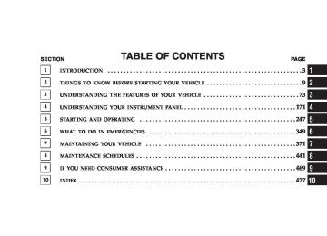
Front Prop Shaft Lubrication Lubricate the front driveshaft grease fitting at each oil change listed in the appropriate Maintenance Schedule for your vehicle (Schedule “A” and “B”). Use Mopar威 type MS-6560 (lithium based grease), or equivalent.
Front Driveshaft Grease Fitting
Front Axle Universal Drive Joints And Pivot Bearings The front axle universal joint and pivot bearings are permanently lubricated and do not require servicing. Body Lubrication Locks and all body pivot points, including such items as seat tracks, doors, liftgate and hood hinges, should be lubricated periodically to assure quiet, easy operation and to protect against rust and wear. Prior to the appli- cation of any lubricant, the parts concerned should be wiped clean to remove dust and grit; after lubricating excess oil and grease should be removed. Particular attention should also be given to hood latching compo- nents to insure proper function. When performing other underhood services, the hood latch, release mechanism and safety catch should be cleaned and lubricated. The external lock cylinders should be lubricated twice a year, preferably in the fall and spring. Apply a small
amount of a high quality lubricant such as Mopar威 Lock Cylinder Lubricant directly into the lock cylinder. Windshield Wiper Blades The rubber edges of the wiper blades and the windshield should be cleaned periodically with a sponge or soft cloth and a mild nonabrasive cleaner. This will remove accu- mulations of salt or road film. Operation of the wipers on dry glass for long periods may cause deterioration of the wiper blades. Always use washer fluid when using the wipers to remove salt or dirt from a dry windshield. Avoid using the wiper blades to remove frost or ice from the windshield. Keep the blade rubber out of contact with petroleum products such as engine oil, gasoline, etc.
MAINTAINING YOUR VEHICLE 395
Windshield Washers The fluid reservoir is located under the hood and should be checked for fluid level at regular intervals. Fill the reservoir with windshield washer solvent only (not ra- diator antifreeze). When refilling the washer fluid reservoir, take some washer fluid and apply it to a cloth or towel and wipe clean the wiper blades, this will help blade performance. To prevent freeze-up of your windshield washer system in cold weather, select a solution or mixture that meets or exceeds the temperature range of your climate. This rating information can be found on most washer fluid containers.
396 MAINTAINING YOUR VEHICLE
WARNING!
Commercially available windshield washer solvents are flammable. They could ignite and burn you. Care must be exercised when filling or working around the washer solution.
After the engine has warmed, operate the defroster for a few minutes to reduce the possibility of smearing or freezing the fluid on the cold windshield. Mopar All Weather Windshield Washer Solution, used with water as directed on the container, aids cleaning action, reduces the freezing point to avoid line clogging, and is not harmful to paint or trim.
Exhaust System The best protection against carbon monoxide entry into the vehicle body is a properly maintained engine exhaust system. Whenever a change is noticed in the sound of the exhaust system, when exhaust fumes can be detected inside the vehicle, or when the underside or rear of the vehicle is damaged, have a competent mechanic inspect the com- plete exhaust system and adjacent body areas for broken, damaged, deteriorated, or mispositioned parts. Open seams or loose connections could permit exhaust fumes to seep into the passenger compartment. In addition, inspect the exhaust system each time the vehicle is raised for lubrication or oil change. Replace as required.
WARNING!
Cooling System
MAINTAINING YOUR VEHICLE 397
Exhaust gases can injure or kill. They contain carbon monoxide (CO) which is colorless and odorless. Breathing it can make you unconscious and can eventually poison you. To avoid breathing CO, fol- low the preceding safety tips.
Exhaust System Rubber Isolator and Loop-Type Hanger — If Equipped Inspect surfaces whenever the vehicle is hoisted for rubber to metal separation or deep cracks. If, however, excessively deep localized cracks are present, or any part of the exhaust system abnormally contacts the under- body hardware, the isolator and/or hanger should be replaced.
Cooling System Maintenance At the intervals shown in the Maintenance Schedules Section of the manual, the system should be drained, flushed and filled. Inspection Check engine coolant (antifreeze) protection every 12
months (before the onset of freezing weather, where applicable). If coolant is dirty in appearance, the system should be drained, flushed and refilled with fresh coolant as specified. Inspect the entire cooling system for leaks. Check the face of the radiator for any accumulation of bugs, leaves, or other foreign matter. If dirty, clean the radiator core with a garden hose. With the engine OFF, gently spray water from the back of the radiator core. Check coolant bottle tube for condition and tightness of connections at coolant bottle and radiator.398 MAINTAINING YOUR VEHICLE
Extremely cold ambient temperature may require the addition of a “winter front” for effective operation of the cab heating/cooling system. Make certain that a percent- age of the radiator is exposed for adequate air flow through the charge air cooler and automatic transmission oil cooler. The percentage of opening must be increased with the increasing ambient air temperature and/or engine load. If the cooling fan can be heard cycling frequently, increase the size of the opening in the winter front. Coolant bottle level check The coolant reserve system provides a quick visual method of determining that the coolant level is adequate. With the engine idling, and warmed to the normal operating temperature, the level of the coolant on the coolant bottle should be between the fluid level marks. Check the coolant level whenever the hood is raised.
The radiator normally remains completely full, so there is no longer a need to remove the coolant pressure cap except for checking coolant freeze point or replacement with new antifreeze coolant.
WARNING!
Never add coolant to the radiator when the engine is overheated. Do not loosen or remove pressure cap to cool overheated engine! The coolant is under pres- sure and severe scalding could result.
Drain, Flush And Refill At intervals shown on the Maintenance Schedules, the system should be drained, flushed and refilled. Refer to your dealer or consult a service manual for proper procedures.
Adding Coolant When adding coolant, or refilling the system, a minimum solution of 50% recommended HOAT ethylene glycol engine coolant (antifreeze) and distilled water should be used. Use higher concentrations (not to exceed 70%) if temperatures below ⫺34°F (⫺37°C) are anticipated. Use only high purity water such as distilled or deionized water when mixing the water/engine coolant solution. The use of lower quality water will reduce the amount of corrosion protection in the engine cooling system. It is the owner’s responsibility to maintain the NOTE: proper level of protection against freezing according to the temperatures occurring in the area where the vehicle is operated. NOTE: Mixing coolant types will decrease the life of the engine coolant and will require more frequent coolant changes.
MAINTAINING YOUR VEHICLE 399
When additional coolant is needed to maintain the proper level, add the recommended concentration of antifreeze and water to the overflow bottle. Do not overfill. NOTE: Failure to follow the antifreeze concentration and replacement recommendations, or failure to use antifreeze formulated to prevent corrosion of all cooling system metals, may result in radiator plugging, overheat- ing, or cooling system leaks such as in core hole plugs.
WARNING!
Never add coolant to the radiator when the engine is overheated. Do not loosen or remove pressure cap to cool an overheated engine. The coolant is under pressure and severe scalding could result.
400 MAINTAINING YOUR VEHICLE
Recommended Engine Coolant Refer to Fluids, Lubricants and Genuine Parts for the correct Fluid type.
CAUTION!
• Mixing of coolants other than specified engine coolant, may result in engine damage, and de- crease corrosion protection. If a non-HOAT cool- ant is introduced into the cooling system in an emergency, it should be replaced with the speci- fied coolant as soon as possible. • Do not use plain water alone or alcohol base engine coolant (antifreeze) products. Do not use additional rust inhibitors or antirust products, as they may not be compatible with the radiator engine coolant and may plug the radiator. • This vehicle has not been designed for use with Propylene Glycol based coolants. Use of Propy- lene Glycol based coolants is not recommended.
Disposal Of Used Engine Coolant Used ethylene glycol based engine coolant is a regulated substance requiring proper disposal. Check with your local authorities to determine the disposal rules for your community. Do not store ethylene glycol-based engine coolant in open containers or allow it to remain in puddles on the ground. Prevent ingestion by animals and children. If ingested by a child, contact a physician immediately. Clean up any ground spills immediately. Coolant Pressure Cap The coolant pressure cap must be fully tightened to prevent loss of coolant and to insure that coolant will return to the radiator from the coolant reserve tank.
MAINTAINING YOUR VEHICLE 401
WARNING!
Never add coolant when the engine is overheated. Do not loosen or remove the pressure cap to cool an overheated engine. Heat causes pressure build up in the cooling system. To prevent scalding or injury, do not remove the pressure cap while the system is hot or under pressure.
CAUTION!
Recheck the cooling system to insure total system is full of coolant.
402 MAINTAINING YOUR VEHICLE
Fan
Inspection Check the fan for cracks and bent or broken blades. If any of these conditions exist, you must replace the fan. Make sure it is securely mounted. NOTE: This service procedure must be performed by a trained service technician. Make arrangements with your authorized Dodge Truck Dealer for this inspection. Charge Air Cooler (Inter-Cooler) The charge air cooler is positioned between the radiator and the air conditioner condenser. Air enters the engine through the air cleaner and passes through the turbo- charger where it is pressurized. This pressurized air rapidly reaches high temperature. The air is then directed through a hose to the charge air cooler and through another hose to the intake manifold of the engine. The air entering the engine has been cooled by about 50 to 100
degrees Fahrenheit. This cooling process enables more efficient burning of fuel resulting in fewer emissions. To guarantee optimum performance of the system, keep the surfaces of the charge air cooler, condenser and radiator clean and free of debris. Periodically check the hoses leading to and from the charge air cooler for cracks or loose clamps resulting in loss of pressure and reduced engine performance. Hoses And Vacuum/Vapor Harnesses Inspect surfaces of hoses and nylon tubing for evidence of heat and mechanical damage. Hard or soft spots, brittle rubber, cracking, tears, cuts, abrasions, and exces- sive swelling indicate deterioration of the rubber. Pay particular attention to those hoses nearest to high heat sources such as the exhaust manifold. Inspect hose routing to be sure hoses do not come in contact with any heat source or moving component which may cause heat damage or mechanical wear.
Insure nylon tubing in these areas has not melted or collapsed. Inspect all hose connections such as clamps and cou- plings to make sure they are secure and no leaks are present. Components should be replaced immediately if there is any evidence of wear or damage that could cause failure. Brake System
Power Disc Brakes (Front and Rear) Disc brakes do not require adjustment; however, several hard stops during the break-in period are recommended to seat the linings and wear off any foreign material. Brake Master Cylinder The fluid level of the master cylinder should be checked when performing under the hood service, or immedi- ately if the brake system warning lamp indicates system failure.
MAINTAINING YOUR VEHICLE 403
The brake master cylinder has a translucent plastic reservoir. On the outboard side of the reservoir, there is a “FULL” dot and an “ADD” dot. The fluid level must be kept within these two dots. Do not add fluid above the full mark because leakage may occur at the cap.
404 MAINTAINING YOUR VEHICLE
With disc brakes the fluid level can be expected to fall as the brake linings wear. However, an unexpected drop in fluid level may be caused by a leak and a system check should be conducted. Refer to Fluids, Lubricants and Genuine Parts for the correct Fluid type.
WARNING!
Use of a brake fluid that may have a lower initial boiling point, or unidentified as to specification, may result in sudden brake failure during hard prolonged braking. You could have an accident.
WARNING!
Overfilling the brake fluid reservoir can result in spilling brake fluid on hot engine parts and the brake fluid catching fire.
Use only brake fluid that has been in a tightly closed container to avoid contamination from foreign matter or moisture.
CAUTION!
Do not allow a petroleum-base fluid to contaminate the brake fluid. Seal damage and loss of brake performance may result.
Brake Hoses Inspection should be performed whenever the brake system is serviced or at intervals specified. Inspect hy- draulic brake hoses for surface cracking, scuffing or worn spots. If there is any evidence of cracking, scuffing, or worn spots, the hose should be replaced immediately! Eventual deterioration of the hose can take place with possible burst failure. Clutch Linkage If the clutch pedal linkage begins to squeak or grunt, the clutch pedal pivot bushings should be lubricated. Refer to Fluids, Lubricants and Genuine Parts for the correct lubricant type. Multipurpose Grease, NLGI Grade 2 E.P. Clutch Hydraulic System The clutch hydraulic system is a sealed maintenance-free system. In the event of leakage or other malfunction, the system must be replaced.
MAINTAINING YOUR VEHICLE 405
Rear Axle And 4x4 Front Driving Axle Fluid Level For Model 9.25 Front Axles and 10.5”/11.5” Rear Axles refer to Fluids, Lubricants and Genuine Parts for the correct lubricant type. For normal service, periodic fluid level checks are not required. When the vehicle is ser- viced for other reasons, the exterior surfaces of the axle assembly should be inspected. When checking the fluid level, the vehicle should be in a level position. The fluid level should be 1/4” ± 1/4” (6.4
mm ± 6.4 mm) below the fill hole on the 9.25” Front Axle. The fluid level should be 3/4” ± 1/4” (19 mm ± 6.4 mm) below the fill hole on all 10.5” and 1/4” ± 1/4” (6.4 mm ± 6.4 mm) on 11.5” Rear Axles.406 MAINTAINING YOUR VEHICLE
Drain And Refill Vehicles operated in normal service do not have regularly scheduled oil changes. If fluid has become contaminated with water or subjected to severe service, follow the recommended change intervals in Maintenance Schedule “B” in Section 8 of this manual. Lubricant Selection Refer to Fluids, Lubricants and Genuine Parts for the correct lubricant type. NOTE: The presence of water in the gear lubricant will result in corrosion and possible failure of differential components. Operation of the vehicle in water, as may be encountered in some off-highway types of service, will require draining and refilling the axle to avoid damage. Limited-Slip Differentials in vehicles equipped with 10.5”/11.5” Axles DO NOT REQUIRE any limited slip oil additive (friction modifiers).
Transfer Case — If Equipped
Fluid Level Check This fluid level can be checked by removing the filler plug. The fluid level should be to the bottom edge of the filler plug hole with the vehicle in a level position. Lubricant Selection Refer to Fluids, Lubricants and Genuine Parts for the correct lubricant type. Manual Transmission — If Equipped
Fluid Level Check This fluid level can be checked by removing the filler plug. If the level of the lubricant is more than 1/4” below the bottom of the filler hole while the vehicle is on level ground, enough lubricant should be added to bring the level to the bottom of the filler hole.
Lubricant Selection for 6-Speed Manual Transmission — If Equipped If it becomes necessary to add fluid or change the fluid, be sure to use the same lubricant or equivalent. Refer to Fluids, Lubricants and Genuine Parts for the correct lubricant type. Automatic Transmission
Fluid Level Check The fluid level should be checked when the engine is fully warmed up and the fluid in the transmission is at normal operating temperature. Operation of the trans- mission with an improper fluid level will greatly reduce the life of the transmission and of the fluid. Check the fluid level whenever the vehicle is serviced. Procedure For Checking Fluid Level To properly check the automatic transmission fluid level, the following procedure must be used:
MAINTAINING YOUR VEHICLE 407
1. The vehicle must be on level ground. 2. The engine should be running at curb idle speed for a minimum of 60 seconds. 3. Fully apply parking brake. 4. Place the gear selector briefly in each gear position ending with the lever in N (Neutral). 5. Remove the dipstick and determine if the fluid is hot or warm. Hot fluid is approximately 180°F (82°C) which is the normal operating temperature after the vehicle has been driven at least 15 miles. The fluid can not be comfortably held between the finger tips. Warm is when fluid is between 85° - 125°F (29° - 52°C). 6. Wipe the dipstick clean and reinsert until seated. Remove dipstick and note reading.
a. If the fluid is hot, the reading should be in the crosshatched area marked “OK”.
408 MAINTAINING YOUR VEHICLE
b. If the fluid is warm, the reading should be between the two holes. If the fluid level indicates low, add sufficient fluid to bring to the proper level.
Fluid is added through the dipstick tube. NOTE: To prevent dirt and water from entering the transmission after checking or replenishing fluid, make certain that the dipstick cap is properly seated. Selection Of Lubricant Refer to Fluids, Lubricants and Genuine Parts for the correct lubricant type. It is important that the transmis- sion fluid be maintained at the prescribed level using the recommended fluid.
CAUTION!
Using a transmission fluid other than the manufac- turers recommended fluid may cause deterioration in transmission shift quality and/or torque converter shudder. Using a transmission fluid other than the manufacturers recommended fluid will result in more frequent fluid and filter changes. Refer to Fluids, Lubricants and Genuine Parts for correct fluid type.
Automatic Transmission Fluid and Filter Change To obtain best performance and long life for automatic transmissions, the manufacturer recommends that they be given regular maintenance service by an Authorized Dodge Dealer or Service Center. It is important that the transmission be adjusted periodically, the fluid main- tained at the correct level, and that it be drained and refilled as specified.
It is important that proper lubricant is used in the transmission. Refer to Fluids, Lubricants and Genuine Parts for the correct lubricant type. A band adjustment and filter change should be made at the time of the oil change. The fluid and filter(s) should be changed and the bands adjusted (if equipped) ) as specified in the Maintenance Schedule (Section 8). Vehicles having severe usage should follow Maintenance Schedule “B” of the Maintenance Schedule (Section 8). Severe usage consists of: • Off-the-highway operation; • Trailer towing; • Snow plow operation; • Prolonged operation with heavy loading, especially in
hot weather.
MAINTAINING YOUR VEHICLE 409
If the transmission is disassembled for any NOTE: reason, the fluid and filter should be changed, and the bands adjusted (if equipped). Special Additives The manufacturer recommends against the addition of any additives to the transmission. Exception to this policy is the use of special dyes to aid in detecting fluid leaks. The use of transmission sealers should be avoided, since they may adversely affect seals. Front Wheel Bearings Front wheel bearings for all Dodge Ram Trucks are sealed-for-life. They do not require greasing or seal replacement. these bearings will “purge” excess grease and the bearing housing will look slightly wet. This is normal. • Periodic inspection for excess play is recommended.
In some instances,
410 MAINTAINING YOUR VEHICLE
• If a bearing assembly is accidentally separated when
servicing the brake rotors, it should be replaced.
Rear Wheel Bearings Clean and repack when brake linings are replaced or rotors resurfaced. Selection Of Lubricating Grease The National Lubricating Grease Institute (NLGI) has developed a symbol (Certification Mark) to aid the vehicle owner in the proper selection of grease for the lubrication of wheel bearings and chassis components. This symbol (an example shown below) is located on the grease container and identifies the application and qual- ity of the grease.
are
There two groups identified: those for wheel bearings (Letter “G”) and those for chassis (Letter “L”) lubrication. Perfor- mance categories within these groups result in dual letter for each group. The letter des- ignations shown in the ex- ample the highest quality level available and when combined as shown can be used for both wheel bearing and chassis lubrication. Use only those greases that have the NLGI symbol on the container along with the proper quality level for your application.
designations
are
Noise Control System Required Maintenance & Warranty For 3500 Two-Wheel Drive and Four-Wheel Drive mod- els over 10,000 lbs. (4 535 kg) Gross Vehicle Weight Rating. All vehicles built over 10,000 lbs. (4 535 kg) Gross Vehicle Weight Rating and manufactured for sale and use in the United States are required to comply with the Federal Government’s Exterior Noise Regulations. These vehicles can be identified by the Noise Emission Control Label located in the operator’s compartment.
MAINTAINING YOUR VEHICLE 411
Required Maintenance For Noise Control Systems The following maintenance services must be performed every 6 months or 6,000 miles (9 600 km), whichever comes first, to assure proper operation of the noise control systems. inspection and service should be performed anytime a malfunction is observed
In addition,
412 MAINTAINING YOUR VEHICLE
or suspected. Proper maintenance of the entire vehicle will help the effectiveness of the noise control systems. Exhaust System Inspect the entire exhaust system for leaks and damaged parts. Devices such as hangers, clamps, and U-bolts should be tight and in good condition. Damaged compo- nents, burned or blown out mufflers, burned or rusted out exhaust pipes should be replaced according to the procedures and specifications outlined in the appropriate service manual. Air Cleaner Assembly Inspect air cleaner housing for proper assembly and fit. Make certain that the air cleaner is properly positioned and that the cover is tight. Check all hoses leading to the air cleaner for tightness. The air filter element must also be clean and serviced according to the instructions out- lined in the Maintenance Schedule Section of this manual.
Tampering With Noise Control System Prohibited Federal law prohibits the following acts or the causing thereof: (1) the removal or rendering inoperative by any person, other than for purposes of maintenance, repair, or replacement, of any device or element of design incorpo- rated into any new vehicle for the purpose of noise control prior to its sale or delivery to the ultimate purchaser or while it is in use, or (2) the use of the vehicle after such device or element of design has been removed or rendered inoperative by any person. Among those acts presumed to constitute tampering are the acts listed below. • AIR CLEANER − Removal of the air cleaner. − Removal of the air cleaner filter element from the air
cleaner housing.
− Removal of the air ducting.
components including the muffler or tailpipe.
• EXHAUST SYSTEM − Removal or rendering inoperative exhaust system • ENGINE COOLING SYSTEM − Removal or rendering inoperative the fan clutch. − Removal of the fan shroud.
Noise Emission Warranty The manufacturer warrants that this vehicle as manufac- tured by the manufacturer, was designed, built and equipped to conform at the time it left the manufacturer’s
MAINTAINING YOUR VEHICLE 413
control with all applicable U.S. EPA Noise Control Regu- lations. This warranty covers this vehicle as designed, built and equipped by the manufacturer, and is not limited to any particular part, component or system of the vehicle manufactured by the manufacturer. Defects in design, assembly or in any part, component or system of the vehicle as manufactured by the manufacturer, which, at the time it left the manufacturer’s control, caused noise emissions to exceed Federal standards, are covered by this warranty for the life of the vehicle.
414 MAINTAINING YOUR VEHICLE
15,000
24 0007,500
12 000Maintenance Log and Service Chart — 24 Valve Cummins Turbo Diesel Noise Systems Maintenance Chart and Service Log — Insert Month, Day, Year under column mileage closest to the mileage at which service was performed. MILES KILOMETERS Exhaust system- inspect Air cleaner assembly-inspect ODOMETER READING PERFORMED BY PERFORMED AT
22,500
36 00030,000
48 00037,500
60 00045,000
72 00052,500
84 00060,000
96 000Noise Systems Maintenance Chart and Service Log — Insert Month, Day, Year under column mileage closest to the mileage at which service was performed.
MAINTAINING YOUR VEHICLE 415
MILES KILOMETERS Exhaust system- inspect Air cleaner assembly-inspect ODOMETER READING PERFORMED BY PERFORMED AT
67,500
108 00075,000
120 00082,500
132 00090,000
144 00097,500
126 00084,000
156 000105,00
168 000112,500
181 000416 MAINTAINING YOUR VEHICLE
Appearance Care and Protection from Corrosion
Protection of Body and Paint from Corrosion Vehicle body care requirements vary according to geo- graphic locations and usage. Chemicals that make roads passable in snow and ice, and those that are sprayed on trees and road surfaces during other seasons, are highly corrosive to the metal in your vehicle. Outside parking, which exposes your vehicle to airborne contaminants, road surfaces on which the vehicle is operated, extreme hot or cold weather and other extreme conditions will have an adverse effect on paint, metal trim, and under- body protection. The following maintenance recommendations will enable you to obtain maximum benefit from the corrosion resistance built into your vehicle. What Causes Corrosion? Corrosion is the result of deterioration or removal of paint and protective coatings from your vehicle.
The most common causes are: • Road salt, dirt and moisture accumulation. • Stone and gravel impact. • Insects, tree sap and tar. • Salt in the air near seacoast localities. • Atmospheric fallout/industrial pollutants. Washing • Wash your vehicle regularly. Always wash your ve- hicle in the shade using Mopar Car Wash or a mild car wash soap, and rinse the panels completely with clear water. • If insects, tar or other similar deposits have accumu- lated on your vehicle, use Mopar Super Kleen Bug and Tar Remover to remove.
• Use Mopar Cleaner Wax to remove road film, stains and to protect your paint finish. Take care never to scratch the paint. • Avoid using abrasive compounds and power buffing that may diminish the gloss or thin out the paint finish.
CAUTION!
Do not use abrasive or strong cleaning materials such as steel wool or scouring powder, which will scratch metal and painted surfaces.
Special Care • If you drive on salted or dusty roads or if you drive near the ocean, hose off the undercarriage at least once a month.
MAINTAINING YOUR VEHICLE 417
• It is important that the drain holes in the lower edges of the doors, rocker panels and trunk be kept clear and open. • If you detect any stone chips or scratches in the paint, touch them up immediately. The cost of such repairs is considered the responsibility of the owner. • If your vehicle is damaged due to an accident or similar cause which destroys the paint and protective coating, have your vehicle repaired as soon as pos- sible. The cost of such repairs is considered the respon- sibility of the owner. • All wheels and wheel trim, especially aluminum and chrome plated wheels should be cleaned regularly with a mild soap and water to prevent corrosion. To remove heavy soil, use Mopar Wheel Cleaner or select a nonabrasive, non-acidic cleaner. Do not use scouring pads, steel wool, a bristle brush or metal polishes. Only Mopar cleaners are recommended. Do not use
418 MAINTAINING YOUR VEHICLE
oven cleaner. Avoid automatic car washes that use acidic solutions or harsh brushes that may damage the wheels’ protective finish. • If you carry special cargo such as chemicals, fertilizers, de-icer salt, etc., be sure that such materials are well packaged and sealed. • If a lot of driving is done on gravel roads, consider • Use Mopar touch up paint on scratches as soon as possible. Your dealer has touch up paint to match the color of your vehicle.
mud or stone shields behind each wheel.
Interior Care Use Mopar Total Clean to clean fabric upholstery and carpeting. Use Mopar Total Clean to clean vinyl upholstery. Mopar Total Clean is specifically recommended for leather upholstery.
Your leather upholstery can be best preserved by regular cleaning with a damp soft cloth. Small particles of dirt can act as an abrasive and damage the leather upholstery and should be removed promptly with a damp cloth. Stubborn soils can be removed easily with a soft cloth and Mopar Total Clean. Care should be taken to avoid soaking your leather upholstery with any liquid. Please do not use polishes, oils, cleaning fluids, solvents, deter- gents, or ammonia based cleaners to clean your leather upholstery. Application of a leather conditioner is not required to maintain the original condition.
WARNING!
Do not use volatile solvents for cleaning purposes. Many are potentially flammable, and if used in closed areas they may cause respiratory harm.
Glass Surfaces All glass surfaces should be cleaned on a regular basis with Mopar Glass Cleaner or any commercial household- type glass cleaner. Never use an abrasive type cleaner. Use caution when cleaning the inside rear window equipped with electric defrosters or the right rear quarter window equipped with the radio antenna. Do not use scrapers or other sharp instruments which may scratch the elements. When cleaning the rear view mirror, spray cleaner on the towel or rag that you are using. Do not spray cleaner directly on the mirror. Cleaning Plastic Instrument Cluster Lenses The lenses in front of the instruments in this vehicle are molded in clear plastic. When cleaning the lenses, care must be taken to avoid scratching the plastic.
MAINTAINING YOUR VEHICLE 419
1. Clean with a wet soft rag. A mild soap solution may be used, but do not use high alcohol content or abrasive cleaners. If soap is used, wipe clean with a clean damp rag. 2. Dry with a soft tissue. Seat Belt Maintenance Do not bleach, dye or clean the belts with chemical solvents or abrasive cleaners. This will weaken the fabric. Sun damage can also weaken the fabric. If the belts need cleaning, use a mild soap solution or lukewarm water. Do not remove the belts from the car to wash them. Replace the belts if they appear frayed or worn or if the buckles do not work properly. Dry with a soft tissue.
420 MAINTAINING YOUR VEHICLE
INTEGRATED POWER MODULE
otherwise the cavity number of each fuse is stamped on the inside cover that corresponds to the following chart.
Cavity Cartridge
Fuse
Mini Fuse 20 Amp Yellow 20 Amp Yellow 20 Amp Yellow 20 Amp Yellow 20 Amp Yellow 10 Amp Red 15 Amp Blue
Description
Power Outlet Console
CCN Door Locks/ BTSI Spare
Spare
Power Sunroof
OCM/VIST Fan/ Wastegate Reverse Lockout Sole- noid Battery (SRT-10
Only)Integrated Power Module Location
An integrated Power Module is located in the engine compartment near the battery. This center contains car- tridge fuses and mini fuses. A description of each fuse and component may be stamped on the inside cover
Cavity Cartridge
Fuse
30 Amp Pink
30 Amp Pink
10
11
12
13
14
Mini Fuse 10 Amp Red
5 Amp Orange 20 Amp Yellow
25 Amp Natural
15 Amp Blue
Description
Heated Mirrors
Off Road Module Power Trx-Off Rd Pkg Sen (Gas Engine Only) IOD-CNN/Radio/ Under Hood Lamp/ WCM/SDARS/HFM Electric Brake
Power-Battery RWAL/ABS Module Feed Park Lamps Left
Cavity Cartridge
Fuse
15
16
17
18
19
20
21
22
40 Amp Green 30 Amp Pink
MAINTAINING YOUR VEHICLE 421
Mini Fuse 20 Amp Yellow 15 Amp Blue 15 Amp Blue
10 Amp Red 10 Amp Red 2 Amp Gray
Description
Trailer Park Lamps
Park Lamps Right
Spare
ABS Pump
Trailer Tow
ORC2
ORC Preset Carrier
IGN Switch Feed
422 MAINTAINING YOUR VEHICLE
Cavity Cartridge
Fuse
20 Amp Blue
40 Amp Green
23
24
25
26
27
28
29
30
Mini Fuse 10 Amp Red
10 Amp Red 20 Amp Yellow
10 Amp Red
10 Amp Red 15 Amp Blue
Description
ECM/WCM/HVC
Subwoofer Amplifier (SRT-10 Only) Power Mirror
Brake Switch/ CHMSL/Stop Lamp Power Seats
Power Run/Start- NCC/WCM/ABS/ RWAL Switches/EC Mirror/ Smart Bar Spare
Cavity Cartridge
Fuse
31
32
33
34
35
36
37
Mini Fuse 10 Amp Red 10 Amp Red
10 Amp Red 10 Amp Red 15 Amp Blue 25 Amp Natural 15 Amp Blue
Description
PCM/Transfer Case Brake HVAC/Ajustable Pedals/Heated Seats Switch LED/Exhaust Brake Power-IGN Run Misc
Spare
CNN Illumination
Audio_Amplifier
Spare
Cavity Cartridge
Fuse
38
39
40
41
42
Mini Fuse 20 Amp Yellow 10 Amp Red 20 Amp Yellow 25 Amp Natural
Description
Power Outlet IP
Sunroof/Seatbelt Ten- sioner Cigar Lighter
Spare
30 Amp Pink
Diesel PCM (Diesel Only)
1. Disconnect the battery negative (-) cable before remov- ing the cover. 2. Use specified fuses only. 3. Always properly reinstall the cover.
MAINTAINING YOUR VEHICLE 423
VEHICLE STORAGE If you are storing your vehicle for more than 21 days, we recommend that you take the following steps to mini- mize the drain on your vehicle’s battery: • Disconnect the Ignition-Off Draw fuse (I.O.D.) fuse located in the Integrated Power Module, located in the engine compartment. The I.O.D. cavity includes a snap-in retainer that allows the fuse to be discon- nected, without removing it from the fuse block. • The electronic shift transfer case should be placed in the 4HI mode and kept in this position to minimize the battery drain. • As an alternative to the above steps you may, discon-
nect the negative cables from both batteries.
NOTE: When reinstalling the IOD fuse, the gages in the Instrument Cluster will do a full sweep, when the ignition key is cycled to RUN. This is a normal condition.
424 MAINTAINING YOUR VEHICLE
REPLACEMENT LIGHT BULBS
LIGHT BULBS — Inside Bulb No. Overhead Console Lights . . . . . . . . . . . . . . . TS 212-2
Dome Light. . . . . . . . . . . . . . . . . . . . . . . . . . . . 7679
All of the inside bulbs are brass or glass wedge base. Aluminum base bulbs are not approved.LIGHT BULBS — Outside Bulb No. Back-Up . . . . . . . . . . . . . . . . . . . . . . . . . . . . . . 3057
Center High Mounted Stop Lamp . . . . . . . . . . . . . 912
Fog Lamp . . . . . . . . . . . . . . . . . . . . . . . . . . . 9006LL Headlamp (Halogen) . . . . . . . . . . . . . . . . . . . . . H13
Side Marker Bulb . . . . . . . . . . . . . . . . . . . . . . . W5W Park & Turn Signal . . . . . . . . . . . . . . . . . . . 3157NAK Rear License Plate Lamp . . . . . . . . . . . . . . . . . . . 168
Rear Cargo Light. . . . . . . . . . . . . . . . . . . . . . . . . 912LIGHT BULBS — Outside Bulb No. Tail & Stop . . . . . . . . . . . . . . . . . . . . . . . . . . . . 3057
Cab Clearance Lights . . . . . . . . . . . . . . . . . . . . . . 168
Dual Rear Wheel Sidemarker Light . . . . . . . . . . . . 168
Dual Rear Wheel Tailgate ID Lights (3) . . . . . . . . . 168BULB REPLACEMENT
Headlight (Halogen)/Front Park and Turn Lights
CAUTION!
This is a halogen bulb. Avoid touching the glass with your fingers. Reduced bulb life will result.
1. Open the hood
2. Remove the two (2) bolts from the front of the head- light housing.
3. Remove the plug from the inner fender well and remove the nut through the access hole.
MAINTAINING YOUR VEHICLE 425
Front Headlight Housing Bolts
Inner Fender Plug
426 MAINTAINING YOUR VEHICLE
NOTE: For easier removal, pull the headlight assembly straight forward, applying the greatest amount of force to the outer edge of the headlight assembly.
Rear Headlight Housing Nut Access
4. Pull the housing out from the fender to allow room to disconnect the electrical connectors.
Headlight Removal
MAINTAINING YOUR VEHICLE 427
6. Twist connector on turn signal/park light bulb 1⁄4 turn and remove connector and bulb from housing. 7. Remove housing from vehicle with headlight halogen bulb in housing. 8. Twist the headlight halogen bulb 1⁄4 turn and remove headlight bulb from the housing. 9. Replace headlight or turn signal bulb. Do not touch the headlight halogen bulb. 10. Reverse procedure for installation of bulbs and hous- ing.
Bulb Removal
5. Unlock and pull connector straight from the base of the headlight halogen bulb.
428 MAINTAINING YOUR VEHICLE
Tail, Stop, Turn and Backup Lights
1. Remove the two (2) screws that pass through the bed sheetmetal.
2. Pull the housing straight out from the body, with a quick motion, to separate the housing from the body. If not pulled straight, locators may be damaged.
3. Push the red lock slide in on the connector and remove the housing from the vehicle. 4. Remove the four (4) screws from the bulb strip in the housing.
MAINTAINING YOUR VEHICLE 429
5. Pull the appropriate bulb straight from the bulb strip.
• Top Bulb: Park/Turn/Hazard • Center Bulb: Stop/Park/Sidemarker • Bottom Bulb: Backup Lights 6. Reverse procedure for installation of bulbs and hous- ing.
430 MAINTAINING YOUR VEHICLE
7. While holding the taillight firmly in place, fasten the top screw first. Center High-Mounted Stoplight With Cargo Light
1. Remove the two (2) screws holding the housing/lens to the body as shown.
2. Separate the connector holding the housing and wir- ing harness to the body.
3. Turn desired bulb socket 1⁄4 turn and remove socket and bulb from housing.
4. Pull desired bulb straight from the socket.
Cab Top Clearance Lights — If Equipped
1. Remove the two screws from the top of the light.
MAINTAINING YOUR VEHICLE 431
• Outside Bulbs: Cargo Lamps • Inside Bulb: Center High Mount Stop Lamp 5. Reverse procedure for installation of bulbs and hous- ing.
432 MAINTAINING YOUR VEHICLE
2. Rotate the socket 1⁄4 turn and pull it from the light assembly.
3. Pull the bulb straight from it’s socket and replace.
Tailgate ID Lights (Dual Rear Wheels) — If Equipped
1. Remove the two screws and housing and access the bulb sockets from the rear.
MAINTAINING YOUR VEHICLE 433
434 MAINTAINING YOUR VEHICLE
2. Turn socket 1⁄4 turn counterclockwise to access the bulb.
Rear Light Bar ID Marker (Dual Rear Wheel) – If Equipped
1. Loosen the two screws and the housing to gain access to the bulb sockets.
3. Pull bulb straight out from socket. 4. Reverse procedure for installation of bulbs and hous- ing.
2. Turn the socket 1/4 turn counterclockwise to access the bulb. 3. Pull the bulb straight out from the socket. 4. Reverse procedure for installation of bulbs and hous- ing.
MAINTAINING YOUR VEHICLE 435
Side Marker Lights (Dual Rear Wheels)
1. Push rearward on the side marker light assembly. 2. Pull the entire assembly from the fender.
436 MAINTAINING YOUR VEHICLE
3. Turn socket 1⁄4 turn counterclockwise and remove from assembly to access the bulb. 4. Pull bulb straight out from socket. 5. Reverse procedure for installation of bulbs and hous- ing. Fog Lights
1. Reach under the vehicle, unlock and twist connector counterclockwise 1⁄4 turn and remove connector and bulb from housing.
2. Pull bulb straight from the connector.
3. Reverse procedure for installation of bulbs and hous- ing.
MAINTAINING YOUR VEHICLE 437
FLUID CAPACITIES FLUID CAPACITIES Fuel
2500 Shortbed Models 2500 Longbed Models 3500 Shortbed Models 3500 Longbed Models
Engine Oil
U.S.
Metric
34 gal. 35 gal. 34 gal. 35 gal.
128L 132L 128L 132L
5.9L Diesel Engine I-6
12.0 qts.
11.4L
Cooling System
5.9L Diesel Engine I-6
7 gal.
26.5L
438 MAINTAINING YOUR VEHICLE
FLUIDS, LUBRICANTS AND GENUINE PARTS
Engine Component Engine Coolant
Engine Oil
Engine Oil Filter Engine Fuel Filter Fuel Selection
Fluids, Lubricants and Genuine Parts Mopar威 Antifreeze/Coolant 5 Year/100,000 Mile Formula HOAT (Hybrid Or- ganic Additive Technology) or equivalent. For the proper quality and SAE Grade oil for your engine, refer to the section ⬙Maintenance Procedures.⬙ Mopar威 Engine Oil Filter, P/N 05083285AA or equivalent. Mopar威 Fuel Filter, P/N 05015581AB or equivalent. Use good quality diesel fuel from a reputable supplier. For most year-round service, No. 2 diesel fuel meeting ASTM specification D-975 will provide good performance. This vehicle is fully compatible with biodiesel blends up to 5% biodiesel meeting ASTM specification D-975. (See page 314 for more information.)
MAINTAINING YOUR VEHICLE 439
Chassis Component Automatic Transmission Transfer Case Manual Transmission Fluid G-56
Clutch Linkage Front and Rear Axle Fluid 2500/3500
Models Brake Master CylinderPower Steering Reservoir
Fluids, Lubricants and Genuine Parts. Mopar威 ATF+4, Automatic Transmission Fluid. Mopar威 ATF+4, Automatic Transmission Fluid. Mopar威 ATF+4, Automatic Transmission Fluid. Multipurpose Grease, NLGI Grade 2 E.P. or equivalent. GL-5 SAE 75W-90 Synthetic or equivalent. 2500/3500 axels do not require limited slip additive. Mopar威 DOT 3 and SAE J1703 should be used or equivalent. If DOT 3
brake fluid is not available, then DOT 4 is acceptable. Use only recom- mended brake fluids. Mopar威 ATF+4, Automatic Transmission Fluid.MAINTENANCE SCHEDULES
CONTENTS
䡵 Emission Control System Maintenance . . . . . . . . 442
䡵 Maintenance Schedules — 24–Valve CumminsTurbo Diesel
. . . . . . . . . . . . . . . . . . . . . . . . . . 442
▫ Schedule “B” . . . . . . . . . . . . . . . . . . . . . . . . 445
▫ Schedule “A” . . . . . . . . . . . . . . . . . . . . . . . . 459M
442 MAINTENANCE SCHEDULES
EMISSION CONTROL SYSTEM MAINTENANCE The “Scheduled” maintenance services, listed in bold type in this section (Section 8) must be done at the times or mileages specified to assure the continued proper functioning of the emission control system. These, and all other maintenance services included in this manual, should be done to provide best vehicle performance and reliability. More frequent maintenance may be needed for vehicles in severe operating conditions such as dusty areas and very short trip driving. Inspection and service also should be done any time a malfunction is suspected. NOTE: Maintenance, replacement, or repair of the emis- sion control devices and systems on your vehicle may be performed by any automotive repair establishment or individual using any automotive part which has been certified pursuant to U.S. EPA or, in the State of Califor- nia, California Air Resources Board regulations.
MAINTENANCE SCHEDULES — 24–VALVE CUMMINS TURBO DIESEL There are two maintenance schedules that show the required service for your vehicle. First is Schedule “B”. It is for vehicles that are operated under one or more of the following conditions that are listed below and at the beginning of the schedule. • Frequent short trips where the engine does not achieve full operating temperature (operating temperature de- fined as 190° F (66° C ) coolant temperature). • Extensive engine idling (over 10 minutes per hour of operation) at ambient temperatures less than 32° F (0° C).
• Driving in dusty conditions. • Frequent trailer towing. • Taxi, police, or delivery service (commercial service).
• Off-road or desert operation. • Extensive operation at high engine speeds (greater than 2900 rpm) and loads (greater than 70% throttle). NOTE: Most vehicles are operated under the conditions listed for Schedule ⬙B⬙. If ANY of these apply to you then change your NOTE: coolant every 101,250 miles (162 000 km) or 60 months, whichever comes first and follow schedule “B” of the ⬙Maintenance Schedules⬙ section of this manual. Second is Schedule “A”. It is for vehicles that are not operated under any of the conditions listed under Sched- ule ⬙B⬙. Use the schedule that best describes your driving condi- tions. Where time and mileage are listed, follow the interval that occurs first.
MAINTENANCE SCHEDULES 443
CAUTION!
Failure to perform the required maintenance items may result in damage to the vehicle.
At Each Stop for Fuel • Check the engine oil level about 15 minutes after a fully warmed engine is shut off. Checking the oil level while the vehicle is on level ground will improve the accuracy of the oil level reading. Add oil only when the level is at or below the ADD or MIN mark. • Check the windshield washer solvent and add if required. When refilling the washer fluid reservoir, take some washer fluid and apply it to a cloth or towel and wipe clean the wiper blades, this will help blade performance.
• Drain water from the fuel filter.
444 MAINTENANCE SCHEDULES
damage.
nals as required.
Once a Month • Check tire pressure and look for unusual wear or • Inspect the batteries and clean and tighten the termi- • Check the fluid levels of coolant reservoir, brake master cylinder, and transmission and transfer case (if equipped), add as needed. • Check Filter Minder™. Replace air cleaner filter • Check all lights and all other electrical items for correct
element if necessary.
operation.
sion components.
At Each Oil Change • Change the engine oil filter. • Inspect the exhaust system. • Inspect the brake hoses. • Inspect the U-Joints ( if equipped) and front suspen- • Check the automatic transmission fluid level. • Check the manual transmission fluid level. • Check the coolant level, hoses, and clamps. • Lubricate outer tie rod ends 2500/3500 (4X4) models • Lubricate Front Drive Shaft Fitting (2500/3500, 4X4).
only.
Schedule “B” Follow schedule “B” if you usually operate your vehicle under one or more of the following conditions. • Frequent short trips where the engine does not achieve full operating temperature (operating temperature de- fined as 190° F (66° C ) coolant temperature). • Extensive engine idling (over 10 minutes per hour of operation) at ambient temperatures less than 32° F (0° C).
• Driving in dusty conditions.
SCHEDULE “B” 445
• Frequent trailer towing. • Taxi, police, or delivery service (commercial service). • Off-road or desert operation. • Extensive operation at high engine speeds (greater than 2900 rpm) and loads (greater than 70% throttle). If ANY of these apply to you then change your NOTE: coolant every 101,250 miles (162 000 km) or 60 months, whichever comes first and follow schedule “B” of the ⬙Maintenance Schedules⬙ section of this manual.
M
446 SCHEDULE “B”
Miles (Kilometers) Change engine oil and engine oil filter. Lubricate Front Drive Shaft Fitting (2500/3500, 4X4). Rotate tires. Check spare tire for proper pressure and correct stowage. Lubricate outer tie rod ends 2500/3500 (4X4) mod- els only. Inspect water pump weep hole for blockage. Replace fuel filter element. Clean the water in fuel sensor. Change rear axle fluid. Change front axle fluid (4X4). Inspect brake linings. Inspect and adjust parking brake if necessary.
3,750
(6 000)7,500
(12 000)11,250
(18 000)15,000
(24 000)18,750
(30 000)Miles (Kilometers) Change engine oil and engine oil filter. Lubricate Front Drive Shaft Fitting (2500/3500, 4X4). Rotate tires. Check spare tire for proper pressure and correct stowage. Lubricate outer tie rod ends 2500/3500 (4X4) mod- els only. Inspect drive belt, replace as required. Inspect fan hub. Inspect damper. Inspect water pump weep hole for blockage. Replace fuel filter element. Clean the water in fuel sensor.
SCHEDULE “B” 447
22,500
(36 000)26,250
(42 000)30,000
(48 000)33,750
(54 000)37,500
(60 000)448 SCHEDULE “B”
Miles (Kilometers) Change rear axle fluid. Change front axle fluid (4X4). Check transfer case fluid level (4X4). Drain and refill automatic transmission fluid. Re- place filter and adjust bands (48RE only).
22,500
(36 000)26,250
(42 000)30,000
(48 000)33,750
(54 000)37,500
(60 000)Miles (Kilometers) Change engine oil and engine oil filter. Lubricate Front Drive Shaft Fitting (2500/3500, 4X4). Rotate tires. Check spare tire for proper pressure and correct stowage. Lubricate outer tie rod ends 2500/3500 (4X4) mod- els only. Inspect drive belt, replace as required. Inspect water pump weep hole for blockage. Replace fuel filter element. Clean the water in fuel sensor. Inspect brake linings. Inspect and adjust parking brake if necessary. Change rear axle fluid. Change front axle fluid (4X4).
SCHEDULE “B” 449
41,250
(66 000)45,000
(72 000)48,750
(78 000)52,500
(84 000)56,250
(90 000)M
450 SCHEDULE “B”
Miles (Kilometers) Change engine oil and engine oil filter. Lubricate Front Drive Shaft Fitting (2500/3500, 4X4). Flush and replace engine coolant at 60 months, if not replaced at 102,000 miles (163 000 km). Rotate tires. Check spare tire for proper pressure and correct stowage. Lubricate outer tie rod ends 2500/3500 (4X4) mod- els only. Inspect drive belt, replace as required. Inspect fan hub. Inspect damper. Inspect water pump weep hole for blockage. Replace fuel filter element. Clean the water in fuel sensor.
60,000
(96 000)63,750
(102 000)67,500
(108 000)71,250
(114 000)75,000
(120 000)Miles (Kilometers) Inspect front wheel bearings. Change rear axle fluid. Change front axle fluid (4X4). Change 6-spd manual transmission (G-56) fluid 2500/3500 models only. Inspect brake linings. Inspect and adjust parking brake if necessary. Drain and refill transfer case fluid (4X4). Drain and refill automatic transmission fluid and change main sump filter (545 RFE only). Drain and refill automatic transmission fluid. Re- place filter and adjust bands (48RE only).
SCHEDULE “B” 451
60,000
(96 000)63,750
(102 000)67,500
(108 000)71,250
(114 000)75,000
(120 000)