- Download PDF Manual
-
the outside air contains smoke, odors, high humidity, or if rapid cooling is desired. This feature allows for recir- culation of interior air only. Air flows through the panel only or through both the panel and floor vents depend-
ing on the selected mode (panel vs bi-level). NOTE: Selecting a “Recirculation Mode” mode does not necessarily consume more fuel than normal A/C mode. Panel
Outside air flows through the outlets located in the instrument panel.
Bi-Level
Outside air flows through the outlets located in the instrument panel and at the floor.
Floor
Mix
Outside air flows primarily through the floor out- lets located under the instrument panel.
Outside air flows in equal proportions through the floor and defroster outlets, and the air conditioning may be on.
Defrost
Outside air is primarily directed to the windshield through the defroster outlets located at the base of the windshield, and the demister outlets located at the edge of each side of the instrument panel, and the air conditioning may be on.
Blower Control
The rotary knob on the left of the control panel is the blower control. Turn the knob clockwise to one of the four positions to obtain the blower speed you desire. To turn the blower off, turn the knob to the far left posi- tion. Temperature Control
The rotary knob at the center of the control panel controls the temperature of the interior air. You can choose your degree of comfort by rotating the knob. The coldest temperature setting is to the extreme left (blue region) and the warmest setting is to the extreme
right (red region) of the rotation.
UNDERSTANDING YOUR INSTRUMENT PANEL 235
Circulation The cab is designed with features to promote outside air circulation. There are grilles in the cab back panel. These are air exhausters that provide the means for regular exchange of cab air. Side window demisters direct air flow specifically to the window glass to help prevent interior fogging of the glass. They are located in the extreme outside upper edges of the instrument panel. The demisters also pro- vide extra air ducts for circulation. They are in operation whenever the Floor, Mix or Defrost modes are in use. To remove frost from the side windows, it is best to use the full defrost mode. NOTE: When you turn off the engine you may hear a hissing sound from under the hood for a short period of time. This is a normal condition that occurs if the air conditioning system has been on. It is not an indication of a problem with the air conditioning system.
236 UNDERSTANDING YOUR INSTRUMENT PANEL
Air Conditioning with Dual Zone Temperature Control — If Equipped With the Dual Zone Temperature Control System, each front seat occupant can independently control the tem- perature of air coming from the outlets on their side of the vehicle.
Dual Zone Control Head
Air Conditioning and Heating Operation To turn on the Air Conditioning, set the fan control at any speed and press the snowflake button located on the control panel. Conditioned air will be directed through the outlets selected by the mode control. A light in the snowflake button shows that the air conditioning is on. Press the button a second time to turn the air condition- ing off. A/C Pushbutton
With the fan control in the ON posi- tion, pushing the A/C button turns on the air conditioning compressor. An indicator light on the button shows that the Air Conditioning compressor is on. Conditioned air is now directed through the mode outlets selected. Pushing the button a second time turns the compressor OFF.
Recirculation Pushbutton
Pushing the Recirculation button al- lows interior air to recirculate continu- ously in any position except defrost and defrost/floor mode for rapid cool down of interior. See “Fast Cooldown” later in this section.
the
Mode Control
The mode control allows you to choose from several patterns of air distribution.
NOTE: To improve your selection choices, the system allows you to operate at intermediate positions between
UNDERSTANDING YOUR INSTRUMENT PANEL 237
the major modes. These intermediate positions are iden- tified by the small dots and give an even blend of both modes. Panel
Outside air flows through the outlets located in the instrument panel. These outlets can be adjusted to
direct the airflow. Bi-Level
Air flows through the outlets located in the instru- ment panel and those located on the floor.
NOTE: There is a difference in temperature between the upper and lower outlets for added comfort. The warmer air goes to the floor outlets. This feature gives improved comfort during sunny but cool conditions. Heat
Outside air flows primarily through the floor out- lets located under the instrument panel.
238 UNDERSTANDING YOUR INSTRUMENT PANEL
Mix
Outside air flows in equal proportions through the floor and defroster outlets.
Blower Control
Defrost
Outside air is primarily directed to the windshield through the defroster outlets located at the base of
the windshield and side window demist outlets. NOTE: The air conditioning compressor operates in both Mix and Defrost or a blend of these modes, even if the A/C button has not been pressed. This dehumidifies the air to help dry the windshield.
The rotary knob on the left of the control panel is the blower control. Turn the knob clockwise to one of the four positions to obtain the blower speed you desire. To turn the blower off, turn the knob to the far left posi- tion.
Dual Zone Temperature Control
Dual Zone Temperature Control
Use this control to regulate the temperature of the air inside the passenger compartment. This is accomplished by having separate temperature control slides for both
UNDERSTANDING YOUR INSTRUMENT PANEL 239
the driver and front passenger. The blue area of the scale indicates cooler temperatures while the red area indicates warmer temperatures. Circulation The cab is designed with features to promote outside air circulation. There are grilles in the cab back panel. These are air exhausters that provide the means for regular exchange of cab air. Side window demisters direct air flow specifically to the window glass to help prevent interior fogging of the glass. They are located in the extreme outside upper edges of the instrument panel. The demisters also pro- vide extra air ducts for circulation. They are in operation whenever the Floor, Mix or Defrost modes are in use. NOTE: When you turn off the engine you may hear a hissing sound from under the hood for a short period of time. This is a normal condition that occurs if the air
240 UNDERSTANDING YOUR INSTRUMENT PANEL
conditioning system has been on. It is not an indication of a problem with the air conditioning system. Operating Tips
Fast Cooldown For a fast cooldown, turn the blower fan rotary knob to the extreme right position, turn the mode control to the panel fresh position, press the snowflake button to turn on the air conditioning, and drive with the windows open for the first few minutes. Once the hot air has been expelled, close the windows and press the Recirculation push-button. When a comfortable condition has been reached, choose a mode position and adjust the tempera- ture control slide and blower speed as necessary to maintain comfort. For high humidity conditions it may be necessary to remain in the Recirculation mode to maintain comfort.
Window Fogging Windows will fog on the inside when the humidity inside the vehicle is high. This often occurs in mild or cool temperatures when it’s rainy or humid. In most cases turning on the Air-conditioning (pressing the snowflake button) will clear the fog. Adjust the temperature control, air direction and blower speed to maintain comfort. As the temperature gets colder it may be necessary to direct air onto the windshield by using MIX Mode position on the control. Adjust the temperature control and blower speed to maintain comfort. Higher blower speeds will reduce fogging. Interior fogging on the windshield can be quickly removed by selecting the defrost mode.
Regular cleaning of the inside of the windows with a non-filming cleaning solution (vinegar and water works very well) will help prevent contaminates (cigarette smoke, perfumes, etc.) from sticking to the windows. Contaminates increase the rate of window fogging. Summer Operation Air conditioned vehicles must be protected with a high quality antifreeze coolant during summer to provide proper corrosion protection and to raise the boiling point of the coolant for protection against overheating. A 50 % concentration is recommended. Refer to Recommended Fluids and Genuine Parts for the proper coolant type. When using the air conditioner in extremely heavy traffic in hot weather especially when towing a trailer, addi- tional engine cooling may be required. If this situation is encountered, operate the transmission in a lower gear to increase engine RPM, coolant flow and fan speed. When
UNDERSTANDING YOUR INSTRUMENT PANEL 241
stopped in heavy traffic, it may be necessary to shift into NEUTRAL and depress the accelerator slightly for fast idle operation to increase coolant flow and fan speed. NOTE: On models equipped with Diesel engines, the idle speed will automatically increase to 1000 rpm at elevated coolant temperatures to improve engine cooling. Your air conditioning system is also equipped with an automatic recirculation system. When the system senses a heavy load or high heat conditions, it may use partial Recirculation A/C mode to provide additional comfort. Winter Operation When operating the system during the winter months, make sure the air intake, located directly in front of the windshield, is free of ice, slush, snow, or other obstruc- tions.
242 UNDERSTANDING YOUR INSTRUMENT PANEL
Operating Tips Chart
STARTING AND OPERATING
CONTENTS
䡵 Starting Procedures – Gas Engines . . . . . . . . . . . 248
▫ Manual Transmission – If Equipped . . . . . . . . 248
▫ Automatic Transmission – If Equipped . . . . . . 248
▫ Normal Starting . . . . . . . . . . . . . . . . . . . . . . 249
▫ If Engine Fails To Start . . . . . . . . . . . . . . . . . 249
▫ After Starting . . . . . . . . . . . . . . . . . . . . . . . . 251
䡵 Starting Procedures – Diesel Engines . . . . . . . . . 251
▫ Manual Transmission – If Equipped . . . . . . . . 252
▫ Automatic Transmission – If Equipped . . . . . . 252▫ Normal Starting Procedure — Engine Manifold
Airtemperature Above 66°F (19°C)
. . . . . . . . . 252
▫ Starting Procedure — Engine Manifold Air
Temperature Below 66°F (19°C)
. . . . . . . . . . . 253
▫ Starting Fluids . . . . . . . . . . . . . . . . . . . . . . . 257
䡵 Normal Operation – Diesel Engine . . . . . . . . . . 257
▫ Cold Weather Precautions . . . . . . . . . . . . . . . 258
▫ Engine Idling — In Cold Weather . . . . . . . . . . 261
▫ Stopping The Engine . . . . . . . . . . . . . . . . . . . 262
▫ Engine Speed Control . . . . . . . . . . . . . . . . . . 263244 STARTING AND OPERATING
▫ Operating Precautions . . . . . . . . . . . . . . . . . . 263
▫ Cooling System Tips — Automatic Transmission 263
䡵 Engine Block Heater — If Equipped . . . . . . . . . 265
䡵 Diesel Exhaust Brake (Engine Braking) – IfEquipped . . . . . . . . . . . . . . . . . . . . . . . . . . . . 265
䡵 Automatic Transmission . . . . . . . . . . . . . . . . . . 266▫ Automatic Transmission With Overdrive (5 Speed
545RFE) — If Equipped . . . . . . . . . . . . . . . . . 267
▫ Automatic Transmission (6 Speed AS68RC) — If
Equipped . . . . . . . . . . . . . . . . . . . . . . . . . . . 273
䡵 Manual Transmission . . . . . . . . . . . . . . . . . . . . 279
▫ Manual Transmission — 6 Speed (G56) . . . . . . 280
▫ Recommended Vehicle Shift Speeds . . . . . . . . 280
▫ Downshifting – Gas Engine . . . . . . . . . . . . . . 281▫ Downshifting – Diesel Engine . . . . . . . . . . . . 282
䡵 Four-Wheel- Drive Operation — If Equipped . . . 283▫ Manually Shifted Transfer Case Operating
Information/Precautions . . . . . . . . . . . . . . . . 283
▫ Shifting Procedure - Manually Shifted Transfer
Case . . . . . . . . . . . . . . . . . . . . . . . . . . . . . . 286
. . . . . . . . . . . . 287▫ Transfer Case Reminder Light ▫ Electronically Shifted Transfer Case Operating
Information/Precautions (4 Position Switch)—If Equipped . . . . . . . . . . . . . . . . . . . . . . . . . . . 288
▫ Shifting Procedure - Electronically Shifted Transfer Case . . . . . . . . . . . . . . . . . . . . . . . . . . . . . . 292
䡵 Limited-Slip Differential — If Equipped . . . . . . . 295
䡵 Power Take Off Operation – If Equipped . . . . . . 296
▫ Stationary Mode . . . . . . . . . . . . . . . . . . . . . . 296▫ Mobile Mode . . . . . . . . . . . . . . . . . . . . . . . . 297
䡵 Driving On Slippery Surfaces . . . . . . . . . . . . . . 298
䡵 Driving Off-Road . . . . . . . . . . . . . . . . . . . . . . . 298
䡵 Parking Brake . . . . . . . . . . . . . . . . . . . . . . . . . 299
䡵 Brake System . . . . . . . . . . . . . . . . . . . . . . . . . . 301
▫ Brake Noise . . . . . . . . . . . . . . . . . . . . . . . . . 302
▫ Four-Wheel Anti-Lock Brake System . . . . . . . . 302
䡵 Power Steering . . . . . . . . . . . . . . . . . . . . . . . . 304
䡵 Tire Safety Information . . . . . . . . . . . . . . . . . . . 305
▫ Tire Markings . . . . . . . . . . . . . . . . . . . . . . . . 305
▫ Tire Identification Number (TIN) . . . . . . . . . . 308
▫ Tire Loading And Tire Pressure . . . . . . . . . . . 310
䡵 Tires — General Information . . . . . . . . . . . . . . . 314STARTING AND OPERATING 245
▫ Tire Pressure . . . . . . . . . . . . . . . . . . . . . . . . . 314
▫ Tire Inflation Pressures . . . . . . . . . . . . . . . . . 315
▫ Radial-Ply Tires . . . . . . . . . . . . . . . . . . . . . . 317
▫ Compact Spare Tire — If Equipped . . . . . . . . . 318
▫ Limited Use Spare — If Equipped . . . . . . . . . 319
▫ Tire Spinning . . . . . . . . . . . . . . . . . . . . . . . . 319
▫ Tread Wear Indicators . . . . . . . . . . . . . . . . . . 320
▫ Life Of Tire . . . . . . . . . . . . . . . . . . . . . . . . . 321
▫ Replacement Tires . . . . . . . . . . . . . . . . . . . . . 321
▫ Alignment And Balance . . . . . . . . . . . . . . . . . 322䡵 Supplemental Tire Pressure Information – If
Equipped . . . . . . . . . . . . . . . . . . . . . . . . . . . . 323
䡵 Tire Chains . . . . . . . . . . . . . . . . . . . . . . . . . . . 323246 STARTING AND OPERATING
䡵 Snow Tires 䡵 Tire Rotation Recommendations
. . . . . . . . . . . . . . . . . . . . . . . . . . . 324
. . . . . . . . . . . . 325
▫ Dual Rear Wheels . . . . . . . . . . . . . . . . . . . . . 326
䡵 Engine Runaway . . . . . . . . . . . . . . . . . . . . . . . 327
䡵 Fuel Requirements . . . . . . . . . . . . . . . . . . . . . . 327
▫ Fuel Requirements (Gas Engines) . . . . . . . . . . 327
▫ Fuel Requirements (6.7L Diesel Engines) . . . . . 331
. . . . . . . . . . . . . . . . . . . . . . . . . . 333
▫ Adding Fuel (Gas Engines) . . . . . . . . . . . . . . 333
▫ Adding Fuel (Diesel Engines) . . . . . . . . . . . . . 335
䡵 Vehicle Loading . . . . . . . . . . . . . . . . . . . . . . . . 338
▫ Certification Label . . . . . . . . . . . . . . . . . . . . . 338
䡵 Trailer Towing . . . . . . . . . . . . . . . . . . . . . . . . . 341䡵 Adding Fuel
▫ Common Towing Definitions . . . . . . . . . . . . . 341
▫ Trailer Hitch Classification . . . . . . . . . . . . . . . 345
▫ Trailer Towing Weights (Maximum Trailer WeightRatings) . . . . . . . . . . . . . . . . . . . . . . . . . . . . 346
▫ Trailer And Tongue Weight . . . . . . . . . . . . . . 346
▫ Towing Requirements . . . . . . . . . . . . . . . . . . 347
▫ Towing Tips . . . . . . . . . . . . . . . . . . . . . . . . . 352
▫ Trailer Towing Mirrors — If Equipped . . . . . . 354
䡵 Snowplow . . . . . . . . . . . . . . . . . . . . . . . . . . . . 355
▫ Before Plowing . . . . . . . . . . . . . . . . . . . . . . . 356
▫ Snowplow Prep Package Model Availability . . 357
▫ Over The Road Operation With SnowplowAttached . . . . . . . . . . . . . . . . . . . . . . . . . . . 358
▫ Methods For Removing Snow . . . . . . . . . . . . 358▫ Operating Tips . . . . . . . . . . . . . . . . . . . . . . . 358
▫ General Maintenance . . . . . . . . . . . . . . . . . . . 359
䡵 Recreational Towing (Behind Motorhome, Etc.) . . 360STARTING AND OPERATING 247
▫ Recreational Towing – 2 Wheel Drive Models ▫ Recreational Towing – 4 Wheel Drive Models
. 360
. 360248 STARTING AND OPERATING
STARTING PROCEDURES – GAS ENGINES The starter should not be operated for more than 15- second intervals. Waiting a few seconds between such intervals will protect the starter from overheating.
WARNING!
Be sure to turn off the engine if you want to rest or sleep in your car. Accidents can be caused by inad- vertently moving the gear selection lever or by pressing the accelerator pedal. This may cause exces- sive heat in the exhaust system, resulting in over- heating and vehicle fire which may cause serious or fatal injuries.
WARNING!
Do not leave children or animals inside parked vehicles in hot weather. Interior heat build up may cause serious injury or death.
Manual Transmission – If Equipped Apply the parking brake, place the gearshift control lever in NEUTRAL and depress the clutch pedal to the floor before starting the vehicle. This vehicle is equipped with a clutch interlocking ignition system. It will not start unless the clutch is fully depressed. Automatic Transmission – If Equipped Start the engine with the selector lever in NEUTRAL or PARK position. Apply the brake before shifting to any driving range.
Normal Starting Normal starting of either a warm or cold engine is obtained without pumping or depressing the accelerator pedal. Turn the key to the START position and release when the engine starts. If the engine fails to start within 10 seconds, turn the key to the OFF position, wait 5
seconds, then repeat the starting procedure. NOTE: This vehicle is equipped with a transmission shift interlocking system. The brake pedal must be depressed to shift out of Park (P).Tip Start Feature — Automatic Transmission Only Do not press the accelerator. Turn the ignition key briefly to START position, and release it. The starter motor will continue to run, but will automatically disengage itself when the engine is running.
STARTING AND OPERATING 249
Ignition Key Positions
If Engine Fails To Start If the engine fails to start after you have followed the normal starting procedure, it may be flooded. Push the accelerator pedal all the way to the floor and hold it there while cranking the engine. This should clear any excess fuel in case the engine is flooded.
250 STARTING AND OPERATING
CAUTION!
WARNING!
To prevent damage to the starter, do not crank the engine for more than 15 seconds at a time. Wait 10 to 15 seconds before trying again.
WARNING!
Never pour fuel or other flammable liquids into the throttle body air inlet opening in an attempt to start the vehicle. This could result in a flash fire causing serious personal injury.
Do not attempt to push or tow your vehicle to get it started. Vehicles equipped with an automatic trans- mission cannot be started this way. Unburned fuel could enter the catalytic converter and once the engine has started, ignite and damage the converter and vehicle. If the vehicle has a discharged battery, booster cables may be used to obtain a start from a booster battery or the battery in another vehicle. This type of start can be dangerous if done improperly. See section 6 of this manual for the proper jump starting procedures and follow them carefully.
If the engine has been flooded, it may start to run, but not have enough power to continue running when the key is
released. If this occurs, continue cranking with the accel- erator pedal pushed all the way to the floor. Release the accelerator pedal and the key once the engine is running smoothly. If the engine shows no sign of starting after two 15
second periods of cranking with the accelerator pedal held to the floor, the normal starting procedure should be repeated. After Starting The idle speed is automatically controlled and will de- crease as the engine warms up.STARTING PROCEDURES – DIESEL ENGINES The starter should not be operated for more than 15- second intervals. Waiting a few seconds between such intervals will protect the starter from overheating.
STARTING AND OPERATING 251
WARNING!
Be sure to turn off the engine if you want to rest or sleep in your car. Accidents can be caused by inad- vertently moving the gear selection lever or by pressing the accelerator pedal. This may cause exces- sive heat in the exhaust system, resulting in over- heating and vehicle fire which may cause serious or fatal injuries.
WARNING!
Do not leave children or animals inside parked vehicles in hot weather. Interior heat build up may cause serious injury or death.
252 STARTING AND OPERATING
Manual Transmission – If Equipped Apply the parking brake, place the gearshift control lever in NEUTRAL and depress the clutch pedal to the floor before starting the vehicle. This vehicle is equipped with a clutch interlocking ignition system. It will not start unless the clutch is fully depressed. Automatic Transmission – If Equipped Start the engine with the selector lever in NEUTRAL or PARK position. Apply the brake before shifting to any driving range. The Cummins Diesel engine is equipped with several features designed to assist cold weather starting and operation: • The engine block heater is a resistance heater installed in the water jacket of the engine just above and behind the oil filter. It requires a 110–115 volt AC electrical outlet with a grounded, three-wire extension cord.
NOTE: The engine block heater cord is a factory in- stalled option. If your vehicle is not equipped, heater cords are available from your authorized Mopar威 dealer. • A 12–volt heater built into the fuel filter housing aids in preventing fuel gelling. It is controlled by a built-in thermostat. • A heated intake air system both improves engine starting and reduces the amount of white smoke generated by a warming engine.
Normal Starting Procedure — Engine Manifold AirTemperature Above 66°F (19°C) Observe the Instrument Panel Cluster lights when start- ing the engine. 1. Always apply the parking brake. 2. Shift into PARK for an automatic transmission. Fully depress and hold the clutch and shift into NEUTRAL for
a manual transmission. Models with manual transmis- sion are equipped with a clutch interlocking cranking system. The clutch must be fully depressed to start the vehicle. 3. Turn the ignition key to the ON position and look at the instrument panel cluster lamps.
CAUTION!
If WATER IN FUEL indicator light remains on DO NOT START engine before you drain water from the fuel filter to avoid engine damage. See Section 7 — Maintaining Your Vehicle, for water drain proce- dures.
4. Turn the ignition key to START and crank the engine. Do not press the accelerator during starting.
STARTING AND OPERATING 253
CAUTION!
Do not crank engine for more than 15 seconds at a time as starter motor damage may result. Turn key to OFF and wait at least two minutes before trying again.
5. When the engine starts, release the key. 6. Check to see that there is oil pressure. 7. Release the parking brake. Starting Procedure — Engine Manifold Air Temperature Below 66°F (19°C)
NOTE: The temperature displayed on the overhead console (if equipped) does not necessarily reflect the engine manifold air temperature. When certain engine temperatures fall below 66°F (19°C) the lamp will remain on indicating the intake manifold heater system is active.
254 STARTING AND OPERATING
Follow the steps in the Normal Starting Procedure ex- cept:
CAUTION!
Do not crank engine for more than 15 seconds at a time or starter motor damage may result. Turn key to OFF and wait at least 2 minutes for starter to cool before repeating start procedure. • The WAIT TO START light will remain on for a period of time (length of time depends on engine tempera- ture). • After the WAIT TO START light goes off, turn the ignition key to START. Do not press the accelerator during starting. • After engine start-up, check to see that there is oil
pressure.
• Allow the engine to idle about three minutes until the manifold heaters have completed the post-heat cycle.
• Release the parking brake and drive. NOTE: Engine idle speed will automatically increase to 1000 rpm at low coolant temperatures to improve engine warm-up. If the engine stalls or if the ignition switch is left NOTE: On for more than 2 minutes after the WAIT TO START light goes out, reset the grid heaters by turning the ignition switch to Off for at least 5 seconds and then back On. Repeat steps 3 through 7 of the normal starting procedure. For Extremely Cold Weather Starting — Engine Manifold Air Temperature Below 0°F (- 18°C) In extremely cold weather below 0°F (- 18°C) it may be beneficial to cycle the manifold heaters twice before
attempting to start the engine. This can be accomplished by turning the ignition OFF for at least 5 seconds and then back ON after the WAIT TO START light has gone off, but before the engine is started. However, repeated cycling of the manifold heaters will result in damage to the heater elements or reduced battery voltage. NOTE: If multiple pre-heat cycles are used before starting, additional engine run time may be required to maintain battery state of charge at a satisfactory level. • If the engine stalls after the initial start, the ignition must be turned to the OFF position for at least 5
seconds and then to the ON position to recycle the manifold heaters.NOTE: Excessive white smoke and poor engine perfor- mance will result if manifold heaters are not recycled. • Heat generated by the manifold heaters dissipates rapidly in a cold engine. If more than two minutes
STARTING AND OPERATING 255
pass between the time the WAIT TO START light goes OFF and the engine is started, recycle the manifold heaters by turning the ignition OFF for at least 5
seconds and then back ON. • If the vehicle is driven and vehicle speed exceeds 19
mph (31 km) before the manifold heater post-heat (after start) cycle is complete, the manifold heaters will shut off. • If the engine is started before the WAIT TO START • If the engine is cranked for more than 10 seconds, thelight turns off, the preheat cycle will turn off.
post-heat cycle will turn off.
NOTE: Engine idle speed will automatically increase to 1000 rpm at low coolant temperatures to improve engine warm-up.
256 STARTING AND OPERATING
NOTE: When a diesel engine is allowed to run out of fuel or the fuel gels at low temperatures, air is pulled into the fuel system. You may try priming as described below. 1. Add a substantial quantity of fuel to the tank (5 to 10
gallons) or eliminate the gelled fuel condition. 2. Crank the engine for 1 to 2 seconds. If the engine does not start, then release the key or starter button back to the RUN position (do not turn the key back to the OFF position). The electric fuel transfer pump will continue to run and purge air from the system for about 20 seconds. After 20 seconds, attempt to start the engine again. 3. Start the engine using the Normal Starting Procedure. 4. Repeat the procedure if the engine does not start.WARNING!
Do not open the high pressure fuel system when cranking the engine or with the engine running. Engine operation causes high fuel pressure. High pressure fuel spray can cause serious injury or death.
NOTE: The engine may run rough until the air is forced from all the fuel lines.
Starting Fluids
WARNING!
STARTING FLUIDS or flammable liquids are NEVER TO BE USED in the Cummins Diesel (see Warning label). Never pour diesel fuel, flammable liquid, starting fluids (ether) into the air cleaner canister, air intake piping, or turbocharger inlet in an attempt to start the vehicle. This could result in a flash fire and explosion causing serious personal injury and engine damage.
The engine is equipped with an automatic electric air preheating system. If the instructions in this manual are followed, the engine should start in all conditions.
STARTING AND OPERATING 257
WARNING!
Do not leave children or animals inside parked vehicles in hot weather. Interior heat build up may cause serious injury or death.
NORMAL OPERATION – DIESEL ENGINE Observe the following when the engine is operating. • All message center lights are off. • Check Engine Lamp is off. • Engine Oil Pressure is above 10 psi (69 kPa) at idle. • Low Oil Pressure light is off. • Voltmeter Operation: • The voltmeter may show a gauge fluctuation if certain engine temperatures are below 66°F (19°C). This cycling operation is caused by the post-heat
258 STARTING AND OPERATING
cycle of the intake manifold heater system. The number of cycles and the length of the cycling operation is controlled by the engine control mod- ule, this time will not exceed 150 seconds. The needle should then stabilize at the approximate operation point. • The cycling action will cause temporary dimming of the headlamps, interior lamps, and also a noticeable reduction in blower motor speed.
Cold Weather Precautions Operation in ambient temperature below 32°F (0°C) may require special considerations. The following charts sug- gest these options: Fuel Operating Range NOTE: Use “Ultra Low Sulfur Diesel Fuels” ONLY.
*No. 1 Ultra Low Sulfur diesel fuel should only be used where extended arctic conditions (-10°F/-23°C) exist. NOTE: • Use of Climatized Ultra Low Sulfur Diesel Fuel or Number 1 Ultra Low Sulfur Diesel Fuel results in a noticeable decrease in fuel economy. • Climatized Ultra Low Sulfur Diesel Fuel is a blend of Number 2 Ultra Low Sulfur and Number 1 Ultra Low Sulfur Diesel Fuels which reduces the temperature at which wax crystals form in fuel.
NOTE: The engine requires the use of “Ultra Low Sulfur Diesel Fuel”. Use of incorrect fuel could result in engine and exhaust system damage. Refer to Fuel Re- quirements in this section for further details on fuel recommendations. Engine Block Heater The engine block heater warms engine coolant and permits quicker starts in cold weather. Connect the heater cord to a ground–fault interrupter protected 110–115 volt AC electrical outlet with a grounded, three-wire exten- sion cord. The engine block heater cord is routed under the hood to the right side and can be located just behind the grille near the headlamp. NOTE: The engine block heater cord is a factory in- stalled option. If your vehicle is not equipped, heater cords are available from your authorized Mopar威 dealer.
STARTING AND OPERATING 259
The block heater must be plugged in at least one hour to have an adequate warming effect on the coolant.
WARNING!
Remember to disconnect the cord before driving. Damage to the 110–115 volt electrical cord could cause electrocution.
NOTE: The block heater will require 110 Volts AC and 6.5 Amps to activate the heater element. Block Heater Usage A. Temperatures below 0°F (-18°C) • Block Heater Required for 15W-40
• Block Heater Recommended for 5W-40
B. Temperatures below - 20°F (-29°C) • Block Heater Required for 5W-40260 STARTING AND OPERATING
Winter Front Usage If a winter front or cold weather cover is to be used, a percentage of the total grille opening area must be left uncovered to provide sufficient air flow to the charge air cooler and automatic transmission oil cooler. The per- centage of opening must be increased with the increasing ambient air temperature and/or engine load. If the cooling fan can be heard cycling frequently, increase the size of the opening in the winter front. A suitable cold weather cover is available from your Mopar威 dealer. Battery Blanket Usage A battery loses 60% of its cranking power as the battery temperature decreases to 0°F (-18°). For the same de- crease in temperature, the engine requires twice as much power to crank at the same RPM. The use of 120 VAC powered battery blankets will greatly increase starting capability at low temperatures. Suitable battery blankets are available from your authorized Mopar威 dealer.
Arctic Operation Where there are no provisions to keep the engine warm when it is operating in ambient temperatures consistently below (-10°F/-23°C), use 5W-40 synthetic engine oil and fuel that meets the requirements in Section 7, “Mainte- nance Procedures,” Engine Oil Selection. Engine Warm-Up Avoid full throttle operation when the engine is cold. When starting a cold engine, bring the engine up to operating speed slowly to allow the oil pressure to stabilize as the engine warms up. NOTE: High-speed, no-load running of a cold engine can result in excessive white smoke and poor engine performance. No-load engine speeds should be kept under 1,200 rpm during the warm-up period, especially in cold ambient temperature conditions.
If temperatures are below 32°F (0°C), operate the engine at moderate speeds for 5 minutes before full loads are applied. Engine Idling — In Cold Weather Avoid prolonged idling in ambient temperatures below 0°F. Long periods of idling may be harmful to your engine because combustion chamber temperatures can drop so low that the fuel may not burn completely. Incomplete combustion allows carbon and varnish to form on piston rings and injector nozzles. Also, the unburned fuel can enter the crankcase, diluting the oil and causing rapid wear to the engine. Excessive idle time can also cause damage to the engine exhaust aftertreat- ment system. NOTE: An optional driver-controlled high idle speed is available on automatic transmission equipped vehicles
STARTING AND OPERATING 261
with speed control. This feature allows the driver to select an elevated idle speed between 1100 and 1500
rpms. Your dealer can enable this feature. NOTE: • If ambienttemperatures are low and the coolant temperature is below 200°F (93°C), the engine idle speed will slowly increase to 1000 RPM after 2 minutes of idle, if the following conditions are met: • foot is off brake pedal and throttle pedal • automatic transmission is in Park (P) • vehicle speed is zero • Applying the throttle will cancel fast idle • If the engine is equipped with an exhaust brake, operating the exhaust brake at idle will greatly im- prove warm up rate and will help keep the engine close to operating temperature during extended idle.
262 STARTING AND OPERATING
Stopping The Engine Idle the engine a few minutes before routine shutdown. After full load operation, idle the engine 3 to 5 minutes before shutting it down. This idle period will allow the lubricating oil and coolant to carry excess heat away from the combustion chamber, bearings, internal components, and turbocharger. This is especially important for turbo- charged, charge air cooled engines, like your Turbo Ram. NOTE: During engine shut down on vehicles equipped with manual transmissions, it is normal for the diesel engine to resonate heavily for a moment during engine shut off. When the engine is connected to a manual transmission, this resonance causes load gear rattle from the transmission. This is commonly referred to as “shut down rattle”. The manufacturer recommends performing engine shut down with the clutch pedal pushed to the floor (clutch disengaged). When engine shut down is performed in this manner the rattle is reduced (not eliminated).
Driving Condition
Stop and
Go
Stop and
Go
Highway Speeds
Load
Turbo- charger
Temperature
Empty
Cool
Medium
Medium
Warm
City Traffic Maximum
GCWR
Highway Speeds Uphill Grade
Maximum
GCWR
Maximum
GCWR
Hot
Idle Time (min.) Be- fore Engine Shutdown Less than
One One
Two
Three
Four
Five
Engine Speed Control
CAUTION!
Prevent overspeeding the engine going down hill. When descending steep grades, use a combination of gears and service brakes to control vehicle/engine speed. Overspeed can cause severe engine damage.
Operating Precautions
Avoid Overheating The Engine The temperature of (a mixture of 50% the coolant ethylene-glycol and 50% water) must not exceed the normal range of the temperature gauge (240°F/116°C) with a 16 psi (110 kPa) radiator cap. Usually the coolant temperature indicated during opera- tion will be to the left of center in the normal range of the gauge.
STARTING AND OPERATING 263
Avoid Low Coolant Temperature Operation Continual operation at low coolant temperature below the normal range on the gauge (140°F/60°C) can be harmful to the engine. Low coolant temperature can cause incomplete combustion which allows carbon and varnish to form on piston rings and injector nozzles. Also, the unburned fuel can enter the crankcase, diluting the lubricating oil and causing rapid wear to the engine. Cooling System Tips — Automatic Transmission To reduce potential for engine and transmission over- heating in high ambient temperature conditions, take the following actions: • City Driving — when stopped, put transmission in neutral and increase engine idle speed. • Highway Driving — reduce your speed.
264 STARTING AND OPERATING
• Up Steep Hills — select a lower transmission gear, but try and keep the torque converter clutch engaged. • Air Conditioning — turn it off temporarily. Do Not Operate The Engine With Low Oil Pressure When the engine is at normal operating temperature, the minimum oil pressures required are:
Idle 700 to 800 RPM . . . . . . . . . . . . . . . 10 psi (69 kPa) Full speed and load . . . . . . . . . . . . . . 30 psi (207 kPa)
CAUTION!
If oil pressure falls to less than normal readings, shut the engine off immediately. Failure to do so could result in immediate and severe engine damage.
Do Not Operate The Engine With Failed Parts Practically all failures give some warning before the parts fail. Be on the alert for changes in performance, sounds, and visual evidence that the engine requires service. Some important clues are: • engine misfiring or vibrating severely • sudden loss of power • unusual engine noises • fuel, oil or coolant leaks • sudden change, outside the normal operating range, in • excessive smoke • oil pressure drop
the engine operating temperature
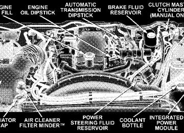
ENGINE BLOCK HEATER — IF EQUIPPED The engine block heater warms engine coolant and permits quicker starts in cold weather. Connect the cord to a standard 110-115 volt AC electrical outlet with a grounded, three-wire extension cord. The engine block heater cord is routed under the hood on the driver side of the vehicle. It has a removable cap that is located on the driver side of the Integrated Power Module.
WARNING!
Remember to disconnect the cord before driving. Damage to the 110-115 volt electrical cord could cause electrocution.
STARTING AND OPERATING 265
DIESEL EXHAUST BRAKE (ENGINE BRAKING) – IF EQUIPPED The Exhaust Brake feature is enabled and disabled by pressing the exhaust brake switch located on the Instru- ment Panel.
Exhaust Brake Switch
266 STARTING AND OPERATING
NOTE: For optimum braking power it is recommended to use the Exhaust Brake while in Tow/Haul Mode. The purpose of the exhaust brake (engine braking) fea- ture is to supply negative (braking) torque to the engine. Typically, the engine braking is used for, but not limited to, vehicle towing applications where vehicle braking can be achieved by the internal engine power, thereby spar- ing the mechanical brakes of the vehicle. Benefits of the exhaust brake are: • vehicle driving control • reduced brake fade • longer brake life • faster cab warm-up.
AUTOMATIC TRANSMISSION
CAUTION!
a complete stop.
Damage to the transmission may occur if the follow- ing precautions are not observed: • Shift into PARK only after the vehicle has come to • Shift into or out of REVERSE only after the vehicle has come to a complete stop and the engine is at idle speed. • Do not shift from REVERSE, PARK, or NEUTRAL into any forward gear when the engine is above idle speed. • Before shifting into any gear, make sure your foot
is firmly on the brake pedal.
WARNING!
It is dangerous to shift the selector lever out of “P” or “N” if the engine speed is higher than idle speed. If your foot is not firmly on the brake pedal, the vehicle could accelerate quickly forward or in re- verse. You could lose control of the vehicle and hit someone or something. Only shift into gear when the engine is idling normally and when your right foot is firmly on the brake pedal.
Automatic Transmission with Overdrive (5 Speed 545RFE) — If Equipped The gear shift selector display, located in the instrument panel cluster, indicates the transmission gear range (the selector is illuminated for night driving). The selector lever is mounted on the right side of the steering column. You must depress the brake pedal, to pull the selector lever out of park (P) position (Brake Interlock System). To
STARTING AND OPERATING 267
drive, move the selector lever from Park or Neutral to the desired drive position. Pull the selector lever toward you when shifting into Reverse, Second, First or Park, or when shifting out of Park. Gear Ranges DO NOT race the engine when shifting from Park or Neutral position into another gear range. “P” Park This gear position supplements the parking brake by locking the transmission. The engine can be started in this range. Never use Park while the vehicle is in motion. Apply the parking brake when leaving the vehicle in this range. Always apply parking brake first, then place the selector in Park position. On 4-wheel drive vehicles be sure that the transfer case is in a drive position!
268 STARTING AND OPERATING
WARNING!
WARNING!
Never use Park position on an automatic transmis- sion as a substitute for the parking brake. Always apply parking brake fully when parked to guard against vehicle movement and possible injury or damage.
WARNING!
Your vehicle could move and injure you and others if it is not completely in P (Park). Check by trying to move the gearshift lever back and forth without first pulling it toward you after you have set it in P. Make sure it is in Park before leaving the vehicle.
It is dangerous to shift the selector lever out of “P” or “N” if the engine speed is higher than idle speed. If your foot is not firmly on the brake pedal, the vehicle could accelerate quickly forward or in re- verse. You could lose control of the vehicle and hit someone or something. Only shift into gear when the engine is idling normally and when your right foot is firmly on the brake pedal.
“R” Reverse Use this range only after the vehicle has come to a complete stop.
“N” Neutral Shift to Neutral when the vehicle is standing for pro- longed periods with the engine running. The engine may be started in this range. Set the parking brake if you must leave the vehicle. “D” Drive This position provides all forward gears, including 3rd gear direct and 4th or 5th gear overdrive (see Overdrive Operation). Use this range for most city and highway driving. “2” Second Use this position for driving slowly in heavy city traffic or on mountain roads where more precise speed control is desirable. Use it also when climbing long grades, and for engine braking when descending moderately steep grades. To prevent excessive engine speed do not exceed 45 mph (72 km/h) in this range.
STARTING AND OPERATING 269
“1” First Use this position for driving up very steep hills and for engine braking at low speeds 20 mph (32 km/h) or less when going downhill. To prevent excessive engine speed, do not exceed 25 mph (40 km/h) in this range. NOTE: Use caution when operating a heavily loaded vehicle in “2” Second or “1” First gear selections in high ambients as torque converter slip can impose significant additional heat load on the cooling system. Overdrive Operation The overdrive automatic transmission contains an elec- tronically controlled fourth and fifth speed (Overdrive). The transmission will automatically shift from Drive to Overdrive if the following conditions are present: • the transmission selector is in Drive; • the engine coolant has reached normal operating tem-
perature;
270 STARTING AND OPERATING
km/h);
• vehicle speed is above approximately 30 mph (48
• the “TOW HAUL O/D OFF” switch has not been • transmission has reached normal operating tempera-activated;
ture. If the vehicle is started in extremely cold tem- NOTE: peratures, the transmission may not shift into Overdrive and will automatically select the most desirable gear for operation at this temperature. Normal operation will resume when the transmission fluid temperature has risen to a suitable level. Refer also to the Note under
torque converter clutch, later in this section. If the transmission temperature gets extremely hot, the transmission will automatically select the most desirable gear for operation at this temperature. If the transmission temperature becomes hot enough the TRANS TEMP light may illuminate and the transmission may downshift out of Overdrive until the transmission cools down. After cooldown, the transmission will resume normal opera- tion. The transmission will downshift from Overdrive to Drive if the accelerator pedal is fully depressed at vehicle speeds above approximately 35 mph (56 km/h).
When To Use “TOW HAUL” and “O/D OFF” Modes
Tow Haul O/D Off Switch
When driving in hilly areas, towing a trailer, carrying a heavy load, etc., and frequent transmission shifting oc- curs, press the “TOW HAUL O/D OFF” button once to select TOW HAUL. This will improve performance and
STARTING AND OPERATING 271
reduce the potential for transmission overheating or failure due to excessive shifting. When operating in “TOW HAUL” mode, 5th gear is disabled and 2-3 and 3-4
shift patterns are modified. Shifts into Overdrive (4th gear) are allowed during steady cruise (for improved fuel economy) and automatic closed-throttle downshifts to 3rd gear (for improved braking) will occur during steady braking. Pressing the “TOW HAUL O/D OFF” button a second time to select O/D OFF will disable 4th and 5th gear completely, which should eliminate any excessive transmission shifting. The “TOW HAUL” or “O/D OFF” light will illuminate in the instrument cluster to indicate when the switch has been activated. Pressing the switch a third time restores normal operation. If the “TOW HAUL” or “O/D OFF” modes are desired, the button must be pressed each time the engine is started.272 STARTING AND OPERATING
When To Lock Out Overdrive When driving in hilly areas, towing a trailer, carrying a heavy load, etc., and frequent 4–3–4 transmission shifting occurs, press the “TOW/HAUL” button twice to disable the overdrive. This will improve performance and reduce the potential for transmission overheating or failure due to excessive shifting. Torque Converter Clutch A feature, designed to improve fuel economy, has been included in the automatic transmission on your vehicle. A clutch within the torque converter engages automati- cally at calibrated speeds. This may result in a slightly different feeling or response during normal operation in high gear. When the vehicle speed drops or during acceleration when the transmission downshifts to second gear, the clutch automatically disengages. NOTE: The torque converter clutch will not engage until the transmission fluid and engine coolant are warm
[usually after 1-3 miles (1.6 - 4.8 km) of driving]. Because the engine speed is higher when the torque converter clutch is not engaged, it may seem as if the transmission is not shifting into Overdrive when cold. This is normal. Pressing the “TOW/HAUL” button, when the transmis- sion is sufficiently warm, will demonstrate that the transmission is able to shift into and out of overdrive. If the vehicle has not been driven in several NOTE: days, the first few seconds of operation after shifting the transmission into gear may seem sluggish. This is due to the fluid partially draining from the torque converter into the transmission. This condition is normal and will not cause damage to the transmission. The torque converter will refill within five seconds of shifting from Park into any other gear position.
STARTING AND OPERATING 273
this range. Never use Park while the vehicle is in motion. Apply the parking brake when leaving the vehicle in this range. Always apply parking brake first, then place the selector in Park position. On 4-wheel drive vehicles be sure that the transfer case is in a drive position!
WARNING!
Never use Park position on an automatic transmis- sion as a substitute for the parking brake. Always apply parking brake fully when parked to guard against vehicle movement and possible injury or damage.
Automatic Transmission (6 Speed AS68RC) — If Equipped The gear shift selector display, located in the instrument panel cluster, indicates the transmission gear range (the selector is illuminated for night driving). The selector lever is mounted on the right side of the steering column. You must depress the brake pedal, to pull the selector lever out of park (P) position (Brake Interlock System). To drive, move the selector lever from Park or Neutral to the desired drive position. Pull the selector lever toward you when shifting into Reverse, Second, First or Park, or when shifting out of Park. Gear Ranges DO NOT race the engine when shifting from Park or Neutral position into another gear range. “P” Park This gear position supplements the parking brake by locking the transmission. The engine can be started in
274 STARTING AND OPERATING
WARNING!
Your vehicle could move and injure you and others if it is not completely in P (Park). Check by trying to move the gearshift lever back and forth without first pulling it toward you after you have set it in P. Make sure it is in Park before leaving the vehicle.
WARNING!
It is dangerous to shift the selector lever out of “P” or “N” if the engine speed is higher than idle speed. If your foot is not firmly on the brake pedal, the vehicle could accelerate quickly forward or in re- verse. You could lose control of the vehicle and hit someone or something. Only shift into gear when the engine is idling normally and when your right foot is firmly on the brake pedal.
“R” Reverse Use this range only after the vehicle has come to a complete stop. “N” Neutral Shift to Neutral when the vehicle is standing for pro- longed periods with the engine running. The engine may be started in this range. Set the parking brake if you must leave the vehicle. “D” Drive This position provides all forward gears, including 4th gear direct and 5th or 6th (if equipped) gear overdrive (see Overdrive Operation). Use this range for most city and highway driving. “3” Third Use this position for driving in slight heavy city traffic or on mountain roads where more precise speed control is desirable. Use it also when climbing long grades, and for
engine braking when descending moderately steep grades. To prevent excessive engine speed do not exceed 40 mph (64 km/h) in this range. “2” Second Use this position for driving on more severe conditions and lower speeds than “3” third. To prevent excessive engine speed do not exceed 25 mph (40 km/h) in this range. “1” First Use this position for driving up very steep hills and for engine braking at low speeds 15 mph (24 km/h) or less when going downhill. To prevent excessive engine speed, do not exceed 15 mph (24 km/h) in this range. NOTE: Use caution when operating a heavily loaded vehicle in “2” Second or “1” First gear selections in high ambients as torque converter slip can impose significant additional heat load on the cooling system.
STARTING AND OPERATING 275
Overdrive Operation The overdrive automatic transmission contains an elec- tronically controlled 5th and 6th (if equipped) speed (Overdrive). The transmission will automatically shift from Drive to Overdrive if the following conditions are present: • the transmission selector is in Drive; • the engine coolant has reached normal operating tem- • vehicle speed is above approximately 38 mph (61
km/h) for 5th gear and 55 mph (89 km/h) for 6th gear; • the “TOW HAUL O/D OFF” switch has not been • transmission has reached normal operating tempera-activated;
perature;
ture.
The transmission will downshift from Overdrive to Drive if the accelerator pedal is fully depressed at vehicle speeds above approximately 37 mph (60 km/h) for 6th to 5th and 29 mph (47 km/h) for 5th to 4th.
276 STARTING AND OPERATING
If the vehicle is started in extremely cold tem- NOTE: peratures, the transmission may not shift into Overdrive and will automatically select the most desirable gear for operation at this temperature. Normal operation will resume when the transmission fluid temperature has risen to a suitable level. Refer also to the Note under torque converter clutch, later in this section. If the transmission temperature gets extremely hot, the transmission will automatically select the most desirable gear for operation at this temperature. If the transmission temperature becomes hot enough the TRANS TEMP light may illuminate and the transmission may downshift out of Overdrive until the transmission cools down. After cooldown, the transmission will resume normal opera- tion.
When To Use “TOW HAUL” and “O/D OFF” Modes
Tow Haul O/D Off Switch
When driving in hilly areas, towing a trailer, carrying a heavy load, etc., and frequent transmission shifting oc- curs, press the “TOW HAUL O/D OFF” button once to select TOW HAUL. This will improve performance and
STARTING AND OPERATING 277
reduce the potential for transmission overheating or failure due to excessive shifting. When operating in “TOW HAUL” mode, 6th gear (if equipped) is disabled and 2-3 and 3-4 and 4–5 shift patterns are modified. Shifts into Overdrive (5th gear) are allowed during steady cruise (for improved fuel economy). Pressing the “TOW HAUL O/D OFF” button a second time to select O/D OFF will disable 5th and 6th gear completely, which should eliminate any excessive transmission shifting. The “TOW HAUL” or “O/D OFF” light will illuminate in the instrument cluster to indicate when the switch has been activated. Pressing the switch a third time restores normal operation. If the “TOW HAUL” or “O/D OFF” modes are desired, the button must be pressed each time the engine is started.
278 STARTING AND OPERATING
WARNING!
Do not use the Tow/Haul feature when driving in icy or slippery conditions as the increased engine brak- ing can cause the rear wheels to slide and the vehicle to swing around with the possible loss of vehicle control, which may cause an accident possibly result- ing in personal injury or death.
When To Lock Out Overdrive When driving in hilly areas, towing a trailer, carrying a heavy load, etc., and frequent 6–5–6 or 5–4–5 transmis- sion shifting occurs, press the “TOW/HAUL” button. This will improve performance and reduce the potential for transmission overheating or failure due to excessive shifting.
Torque Converter Clutch A feature, designed to improve fuel economy, has been included in the automatic transmission on your vehicle. A clutch within the torque converter engages automati- cally at calibrated speeds. This may result in a slightly different feeling or response during normal operation in high gear. When the vehicle speed drops or during acceleration when the transmission downshifts to 1st gear, the clutch automatically disengages. NOTE: The torque converter clutch will not engage until the transmission fluid and engine coolant are warm [usually after 1-3 miles (1.6 - 4.8 km) of driving]. Because the engine speed is higher when the torque converter clutch is not engaged, it may seem as if the transmission is not shifting into Overdrive when cold. This is normal. Pressing the “TOW/HAUL” button, when the transmis- sion is sufficiently warm, will demonstrate that the transmission is able to shift into and out of overdrive.
If the vehicle has not been driven in several NOTE: days, the first few seconds of operation after shifting the transmission into gear may seem sluggish. This is due to the fluid partially draining from the torque converter into the transmission. This condition is normal and will not cause damage to the transmission. The torque converter will refill within five seconds of shifting from Park into any other gear position.
MANUAL TRANSMISSION
WARNING!
You or others could be injured if you leave the vehicle unattended without having the parking brake fully applied. The parking brake should al- ways be applied when the driver is not in the vehicle, especially on an incline.
STARTING AND OPERATING 279
Truck models with manual transmission are equipped with a clutch interlocking ignition system. The clutch pedal must be fully depressed to start the vehicle. Fully depress the clutch pedal before shifting gears. As you release the clutch pedal, lightly depress the accelera- tor pedal. To shift into Reverse, come to a complete stop. Depress the clutch and pause briefly to allow the gear train to stop. Move the shift lever from the Neutral position straight across and back into Reverse. Never drive with your foot resting on the clutch pedal, or attempt to hold the vehicle on a hill with the clutch pedal partially engaged, as this will cause abnormal wear on the clutch.
280 STARTING AND OPERATING
Manual Transmission — 6 Speed (G56) Your vehicle may be equipped with the G56 manual transmission. This transmission has a “creeper” 1st gear which should be used to start from a standing position when carrying a payload or towing a trailer. Damage to the clutch can result from starting in 2nd or 3rd gear with a loaded vehicle. An unloaded vehicle may be launched in 2nd gear. Use each gear in numerical order – do not skip a gear. For most city driving you may find it easier to use only 1st through 5th gear ranges. For steady highway driving with light accelerations, 6th gear is recommended. To shift into 5th gear, move the shift lever to the right beyond the spring pressure point and push it forward. When shifting from 5th to 4th gear, pull the lever down toward you in one motion. Do not pull the lever sharply
left as you may shift accidentally into 2nd gear and damage the transmission. To shift into Reverse, come to a complete stop. Depress the clutch and pause briefly to allow the gear train to stop. Reverse has a “crash-through” lockout feature. Move the shift lever from the Neutral position straight across, in one swift motion, and down into Reverse. Recommended Vehicle Shift Speeds To utilize your manual transmission efficiently for both fuel economy and performance, it should be upshifted as listed in recommended shift speed chart. Shift at the vehicle speeds listed for acceleration. Earlier upshifts during cruise conditions (steady speeds) will result in increased fuel economy, and may be used as indicated.
6 Speed Manual Transmission Shift Speeds in mph
(km//h)
Accel
4 to 5
3 to 4
2 to 3
Engine Mode 6.7L Turbo Diesel Engine 6 Speed Manual Transmission Shift Speeds in mph
40 (64)
45 (72)
25 (40)
15 (24)
Cruise
5 to 6
(km//h)
En- gine Mode 5.7L Accel Gas En- gine
Cruise
1 to 2
2 to 3
3 to 4
4 to 5
5 to 6
15 (24)
25
(40)40 (64)
45
(72)50 (81)
STARTING AND OPERATING 281
Downshifting – Gas Engine Moving from a high gear down to a lower gear is recommended to preserve brakes when driving down steep hills. In addition, downshifting at the right time provides better acceleration when you desire to resume speed. For acceleration at speeds less than 20 mph (30
km/h), 2nd gear is recommended.CAUTION!
When descending a hill, be very careful to downshift one gear at a time to prevent overspeeding the engine which can cause valve damage.
To prevent clutch and transmission damage, your vehicle should be downshifted at speeds no greater than those listed in the Maximum Recommended Downshifting Speed chart.
282 STARTING AND OPERATING
Maximum Recommended Downshifting Speeds
Downshifting – Diesel Engine
Gear Selec- tion Maxi- mum Speed
1st
2nd
3rd
4th
5th
20 mph
35 mph
55 mph
(32
(56
(88
km/h)
km/h)
km/h)
75 mph
(120
km/h)85 mph
(135
km/h)CAUTION!
Failure to follow the recommended downshifting speeds may cause the engine to over speed and / or damage the clutch disc even if the clutch pedal is depressed.
Moving from a high gear down to a lower gear is recommended to preserve brakes when driving down steep hills. In addition, downshifting at the right time provides better acceleration when you desire to resume speed. Downshift progressively. Do not skip gears to avoid overspeeding the engine and clutch. For accelera- tion at speeds less than 15 mph (25 km/h), 2nd gear is recommended.
CAUTION!
When descending a hill, be very careful to downshift one gear at a time to prevent overspeeding the engine which can cause valve damage.
To prevent clutch and transmission damage, your vehicle should be downshifted at speeds no greater than those listed in the Maximum Recommended Downshifting Speed chart. Maximum Recommended Downshifting Speeds
Gear Selec- tion Maxi- mum Speed
1st
2nd
3rd
4th
5th
10 mph
19 mph
32 mph
50 mph
(16
(31
(51
(80
km/h)
km/h)
km/h)
km/h)
68 mph
(109
km/h)FOUR-WHEEL- DRIVE OPERATION — IF EQUIPPED Four-Wheel-Drive Dodge Ram Trucks are equipped with either a Manually Shifted transfer case or an Electroni- cally Shifted transfer case. See the operating instructions for your transfer case, located within this section.
STARTING AND OPERATING 283
Manually Shifted Transfer Case Operating Information/Precautions The transfer case provides 4 mode positions - 2 (rear)- wheel-drive high range, 4-wheel-drive high range, neu- tral, and 4-wheel-drive low range. This transfer case is intended to be driven in the 2-wheel- drive position (2H) for normal street and highway con- ditions such as dry hard surfaced roads. When additional traction is required the transfer case 4H and 4L positions can be used to lock the front and rear driveshafts together and force the front and rear wheels to rotate at the same speed. This is accomplished by simply moving the shift lever to the desired positions. The 4H and 4L positions are intended for loose, slippery road surfaces only. Driving in the 4H and 4L positions on dry hard surfaced roads may cause increased tire wear and damage to the driveline components.
284 STARTING AND OPERATING
The 4-wheel-drive light (4WD), located in the instrument cluster, alerts the driver that the vehicle is in 4-wheel drive and that the front and rear driveshafts are locked together. This light illuminates when the transfer case is shifted to either the 4H or 4L positions. There is no light for the 2H or N (Neutral) positions. When operating your vehicle in 4L, the engine speed is approximately three times that of the 2H or 4H positions at a given road speed. Take care not to overspeed the engine and do not exceed 25 mph (40 km/h). Proper operation of 4-wheel-drive vehicles depends on tires of equal size, type and circumference on each wheel. Any difference will adversely affect shifting and can cause damage to the transfer case.
NOTE: Do not attempt to make a shift while only the front or rear wheels are spinning. The transfer case is not equipped with a synchronizer and therefore the front and rear driveshaft speeds must be equal for the shift to take place. Shifting while only the front or rear wheels are spinning can cause damage to the transfer case. Because 4-wheel drive provides improved traction, there is a tendency to exceed safe turning and stopping speeds. Do not go faster than road conditions permit. NOTE: Delayed shifts out of four-wheel drive may be experienced due to uneven tire wear, low or uneven tire pressures, excessive vehicle loading, or cold tempera- tures.
WARNING!
You or others could be injured if you leave the vehicle unattended with the transfer case in the Neutral (N) position without first fully engaging the parking brake. The transfer case Neutral (N) position disengages both the front and rear driveshafts from the powertrain and will allow the vehicle to move regardless of the transmission position. The parking brake should always be applied when the driver is not in the vehicle.
For additional information on the appropriate use of each transfer case mode position see the information below:
STARTING AND OPERATING 285
2H Rear Wheel Drive High Range - Normal street and highway driving. Dry hard surfaced roads. 4H 4-Wheel-Drive High Range - Locks the front and rear driveshafts together. Forces the front and rear wheels to rotate at the same speed. Additional traction for loose, slippery road surfaces only. Neutral - Disengages both the front and rear driveshafts from the powertrain. To be used for flat towing behind another vehicle. See Recreational Towing for more infor- mation.
286 STARTING AND OPERATING
4L 4-Wheel-Drive Low Range - Low speed 4-wheel-drive. Locks the front and rear driveshafts together. Forces the front and rear wheels to rotate at the same speed. Additional traction and maximum pulling power for loose, slippery road surfaces only. Do not exceed 25 mph (40 km/h). Vehicle’s equipped with the AISIN (AS68RC) Automatic Transmission, Overdrive gear (5th and 6th) will be disabled when the transfer case is in 4L.
Shifting Procedure - Manually Shifted Transfer Case
Manual Transfer Case Shifter
2H ⇔ 4H Shifting between 2H and 4H can be made with the vehicle stopped or in motion. If the vehicle is in motion, shifts can be made up to 55 mph (88 km/h). With the
vehicle in motion, the transfer case will engage / disen- gage faster if you momentarily release the accelerator pedal after completing the shift. Apply a constant force when shifting the transfer case lever. 2H or 4H ⇔ 4L With the vehicle rolling at 2 to 3 mph (3 to 5 km/h), shift an automatic transmission to N (Neutral) or depress the clutch on a manual transmission. While the vehicle is coasting at 2 to 3 mph (3 to 5 km/h), shift the transfer case lever firmly to the desired position. Do not pause in transfer case N (Neutral). NOTE: Pausing in transfer case N (Neutral) in vehicles equipped with an automatic transmission may require shutting the engine OFF to avoid gear clash while completing the shift. If difficulty occurs, shift automatic transmission to N (Neutral), hold foot on brake, and turn engine OFF. Make shift to the desired mode.
STARTING AND OPERATING 287
NOTE: Shifting into or out of 4L is possible with the vehicle completely stopped, however difficulty may oc- cur due to the mating clutch teeth not being properly aligned. Several attempts may be required for clutch teeth alignment and shift completion to occur. The pre- ferred method is with the vehicle rolling 2 to 3 mph (3 to 5 km/h). Avoid attempting to engage or disengage 4L with the vehicle moving faster than 2 to 3 mph (3 to 5
km/h). NOTE: Do not attempt to shift to or from 4L while the transmission is in gear or clutch is engaged. Transfer Case Reminder Light The four-wheel-drive operating light (4WD), located in the instrument cluster, is used to alert the driver that the front axle is fully engaged and all four wheels are driving.288 STARTING AND OPERATING
Electronically Shifted Transfer Case Operating Information/Precautions (4 Position Switch)—If Equipped
Transfer Case Switch
This is an electric shift transfer case and is operated by the 4WD Control Switch (Transfer Case Switch), which is located on the instrument panel.
This Electronically Shifted transfer case provides 4 mode positions: 2 (rear) wheel drive high range, 4 wheel drive lock range, 4 wheel drive low range, and neutral. The Electronically Shifted transfer case is designed to be driven in the 2 wheel drive position (2WD) for normal street and highway conditions (dry hard surfaced roads). When additional traction is required, the transfer case 4WD LOCK and 4WD LOW positions can be used to lock the front and rear driveshafts together and force the front and rear wheels to rotate at the same speed. This is accomplished by rotating the 4WD Control Switch to the desired position - see Shifting Procedure section for specific shifting instructions. The 4WD LOCK and 4WD LOW positions are designed for loose, slippery road surfaces only. Driving in the 4WD LOCK and 4WD LOW positions on dry hard surfaced roads may cause in- creased tire wear and damage to the driveline compo- nents.
STARTING AND OPERATING 289
Transfer Case Position Indicator Lights — Electronically Shifted Transfer Case Only Transfer case position indicator lights are located in the instrument cluster and indicate the current and desired transfer case selection. When you select a different trans- fer case position, the indicator lights will do the follow- ing: If All Shift Conditions are Met 1. The current position indicator light will turn OFF. 2. The selected position indicator light will flash until the transfer case completes the shift. 3. When the shift is complete, the indicator light for the selected position will stop flashing and remain ON. If One or More Shift Conditions are not Met 1. The indicator light for the current position will remain ON.
NOTE: The transfer case Neutral (N) position is selected by depressing the recessed button located on the lower left hand corner of the 4WD Control Switch. The transfer case Neutral (N) position is to be used for recreational towing only. See the Recreational Towing section for specific procedures on shifting into and out of Neutral (N).
290 STARTING AND OPERATING
2. The newly selected position indicator light will con- tinue to flash. 3. The transfer case will not shift. NOTE: Before retrying a selection, make certain that all the necessary requirements for selecting a new transfer case position have been met. To retry the selection, turn the control knob back to the current position, wait five (5) seconds, and retry selection. To find the shift require- ments, refer to the ⬙Shifting Procedure⬙ for your transfer case, located in this section of the owner’s manual. The “SERVICE 4WD” warning light monitors the electric shift 4WD system. If this light remains on after engine start up or illuminates during driving, it means that the 4WD system is not functioning properly and that service is required.
WARNING!
Always engage the parking brake when powering down the vehicle if the ⴖService 4WDⴖ light is illuminated. Not engaging the parking brake may allow the vehicle to roll which may cause personal injury.
NOTE: Do not attempt to make a shift while only the front or rear wheels are spinning, as this can cause damage to driveline components. When operating your vehicle in 4WD LOW, the engine speed is approximately three times that of the 2WD or 4WD LOCK positions at a given road speed. Take care not to overspeed the engine and do not exceed 25 mph (40 km/h).
Proper operation of 4 wheel drive vehicles depends on tires of equal size, type and circumference on each wheel. Any difference in tire size can cause damage to the transfer case. Because 4 wheel drive provides improved traction, there is a tendency to exceed safe turning and stopping speeds. Do not go faster than road conditions permit.
STARTING AND OPERATING 291
WARNING!
You or others could be injured if you leave the vehicle unattended with the transfer case in the Neutral (N) position without first fully engaging the parking brake. The transfer case Neutral (N) position disengages both the front and rear driveshafts from the powertrain and will allow the vehicle to move regardless of the transmission position. The parking brake should always be applied when the driver is not in the vehicle.
For additional information on the appropriate use of each transfer case mode position see the information below: 2WD Rear Wheel Drive High Range - Normal street and highway driving. Dry hard surfaced roads.
292 STARTING AND OPERATING
4WD LOCK 4 Wheel Drive Lock Range - Locks the front and rear driveshafts together. Forces the front and rear wheels to rotate at the same speed. Additional traction for loose, slippery road surfaces only. 4WD LOW 4 Wheel Drive Low Range - Low speed 4 wheel drive. Locks the front and rear driveshafts together. Forces the front and rear wheels to rotate at the same speed. Additional traction and maximum pulling power for loose, slippery road surfaces only. Do not exceed 25 mph (40 km/h). Neutral - Disengages both the front and rear driveshafts from the powertrain. To be used for flat towing behind another vehicle. See Recreational Towing for more infor- mation.
Shifting Procedure - Electronically Shifted Transfer Case
Transfer Case Switch
If any of the requirements to select a new NOTE: transfer case position have not been met, the transfer case will not shift.The indicator light for the previous position will remain ON and the newly selected position indicator
light will continue to flash until all the requirements for the selected position have been met. To retry a shift: return the control knob back to the original position, make certain all shift requirements have been met, wait five (5) seconds and try the shift again. If all the requirements to select a new transfer NOTE: case position have been met, the current position indica- tor light will turn OFF, the selected position indicator light will flash until the transfer case completes the shift. When the shift is complete, the indicator light for the selected position will stop flashing and remain ON. 2WD⇔ 4WD LOCK Rotate the 4WD Control Switch to the desired position. Shifts between 2WD and 4WD LOCK can be done with the vehicle stopped or in motion. With the vehicle in motion, the transfer case will engage / disengage faster if you momentarily release the accelerator pedal after turn- ing the control switch. If the vehicle is stopped, the
STARTING AND OPERATING 293
ignition key must be in the ON position with the engine either RUNNING or OFF. This shift cannot be completed if the key is in the accessory position. NOTE: The 4x4 system will not allow shifts between 2WD/4WD LOCK if the front and/or rear wheels are spinning (no traction). In this situation the selected position indicator light will flash and the original posi- tion indicator light will remain ON. At this time, reduce speed and stop spinning the wheels to complete the shift. 2WD or 4WD LOCK⇔ 4WD LOW NOTE: When shifting into or out of 4WD LOW some gear noise may be heard. This noise is normal and is not detrimental to the vehicle or occupants. Shifting can be performed with the vehicle rolling 2 to 3
mph (3 to 5 km/h) or completely stopped. USE EITHER OF THE FOLLOWING PROCEDURES:294 STARTING AND OPERATING
Preferred Procedure 1. With engine RUNNING, slow vehicle to 2 to 3 mph (3
to 5 km/h). 2. Shift the transmission into NEUTRAL (depress clutch on manual transmissions). 3. While still rolling, rotate the transfer case control switch to the desired position. 4. After the desired position indicator light is ON (not flashing), shift transmission back into gear (release clutch on manual transmissions). Alternate Procedure 1. Bring the vehicle to complete stop. 2. With the key ON and the engine either OFF or RUNNING, shift the transmission into NEUTRAL (de- press clutch on manual transmissions).3. Rotate the transfer case control switch to the desired position. 4. After the desired position indicator light is ON (not flashing), shift transmission back into gear (release clutch on manual transmissions). If steps 1 or 2 of either the Preferred or Alternate NOTE: Procedure are not satisfied prior to attempting the shift then the desired position indicator light will flash con- tinuously while the original position indicator light is ON, until all requirements have been met. NOTE: The ignition key must be ON for a shift to take place and for the position indicator lights to be operable. If the key is not ON then the shift will not take place and no position indicator lights will be on or flashing. NOTE: than 21 days, refer to the section on “Vehicle Storage.”
If your are leaving your vehicle stored for longer
LIMITED-SLIP DIFFERENTIAL — IF EQUIPPED The limited-slip differential provides additional traction on snow, ice, mud, sand and gravel, particularly when there is a difference between the traction characteristics of the surface under the right and left rear wheels. During normal driving and cornering, the limited-slip unit per- forms similarly to a conventional differential. On slip- pery surfaces, however, the differential delivers more of the driving effort to the rear wheel having the better traction. The limited-slip differential is especially helpful during slippery driving conditions. With both rear wheels on a slippery surface, a slight application of the accelerator will supply maximum traction. When starting with only one rear wheel on an excessively slippery surface, slight momentary application of the parking brake may be necessary to gain maximum traction.
STARTING AND OPERATING 295
WARNING!
On vehicles equipped with a limited-slip differen- tial, never run the engine with one rear wheel off the ground, since the vehicle may drive through the rear wheel remaining on the ground. You could lose control of the vehicle.
Care should be taken to avoid sudden accelerations when both rear wheels are on a slippery surface. This could cause both rear wheels to spin, and allow the vehicle to slide sideways on the crowned surface of a road or in a turn.
296 STARTING AND OPERATING
POWER TAKE OFF OPERATION – IF EQUIPPED The 3500 Dodge Chassis Cab vehicle, when equipped with either the automatic 6 speed or manual G-56 6 speed transmissions, will allow for an aftermarket upfit with a transmission driven PTO (power take off). The customer will have the ability to operate the PTO in either a “stationary” or “mobile” mode. The vehicles will be factory set to the “stationary” mode. In order to select the “mobile” mode a DaimlerChrysler Dealership is required to modify the vehicles settings using their proprietary Dealer service tool. Stationary Mode
To operate the PTO in this mode the vehicle must meet the following conditions: • Be in “park” position (vehicles equipped with auto- • Upfitter provider (on/off) switch has been activated
matic transmission)
manual transmission)
• Parking brake applied (vehicles equipped with • Vehicle must be running • No vehicle, brake or clutch switch faults present • PTO must be correctly installed using the vehicle
provided circuits
The customer has the choice to operate the PTO by utilizing the cruise control switches or by utilizing a remote control (provided by the PTO supplier). To oper- ate the feature using the cruise control switches the customer must first activate the up fitter provided on/off switch. Next, the cruise control “on” switch is selected. Following this step the “set” switch must be depressed. The vehicle is now in the PTO mode and is ready for use. In order to increase or decrease the engine idle speed, to optimize the PTO function, the “accel” and “decel” cruise switches can be used respectively. To disengage PTO
operation and return to “standard vehicle operation” simply turn the up fitter provided on/off switch to the off position. To operate the PTO via a remote switch the customer must make sure the above conditions are met. It is vital for proper operation that the PTO and remote have been installed correctly paying special attention to ensure the vehicle provided wiring has been connected properly. This is the responsibility of the installer of the PTO and switches/remote system. It is the responsibility of the PTO manufacturer to ensure that their electrical (switches and remote) system is compatible with the vehicle’s electrical architecture and software functionality. Mobile Mode
To operate the PTO in this mode the vehicle must meet the following conditions:
STARTING AND OPERATING 297
proprietary service tool
• Dealer selected “mobile” mode activated via Dealer • Upfitter provider (on/off) switch has been activated • Vehicle must be in “park” or “drive” position (vehicles • Parking brake must not be applied • No vehicle, brake or clutch switch faults present • Vehicle must be running • PTO must be correctly installed using the vehicle
equipped with automatic transmission)
provided circuits
The customer may choose to use the PTO while the vehicle is moving. To do so the PTO function must be activated prior to taking the vehicle out of “park”. This is accomplished by activating the up fitter provided PTO on/off switch. At this point the customer may place the vehicle in a forward or reverse gear and have PTO
298 STARTING AND OPERATING
operation. To disengage PTO operation and return to “standard vehicle operation” simply turn the up fitter provided on/off switch to the off position. NOTE: For application specific information with respect to PTO and pump requirements and additional vehicle information (wiring schematics, preset idle values, en- gine speed limits, and vehicle hardware and software requirements) please refer to the Dodge Body Builders Guide by accessing “www.dodge.com/bodybuilder” and choosing the appropriate links.
DRIVING ON SLIPPERY SURFACES When driving on wet or slushy roads, it is possible for a wedge of water to build up between the tire and road surface. This is known as hydroplaning and may cause partial or complete loss of vehicle control and stopping ability. To reduce this possibility, the following precau- tions should be observed:
1. Slow down during rainstorms or when roads are slushy. 2. Slow down if road has standing water or puddles. 3. Replace tires when tread wear indicators first become visible. 4. Keep tires properly inflated. 5. Maintain sufficient distance between your vehicle and the car in front to avoid a collision in a sudden stop.
DRIVING OFF-ROAD Care should be taken when attempting to climb steep hills or driving diagonally across a hill or slope. If natural obstacles force you to travel diagonally up or down a hill, choose a mild angle and keep as little side tilt as possible. Keep the vehicle moving and make turns slowly and cautiously.
If you must back down a hill, back straight down using REVERSE gear. Never back down in NEUTRAL, or diagonally across the hill. When driving over sand, mud, and other soft terrain, shift to low gear and drive steadily. Apply the accelerator slowly to avoid spinning the wheels. DO NOT REDUCE the tire pressures for this type of driving. NOTE: After off-road usage, particularly in sand or mud, inspect the underside of the vehicle for accumu- lated dirt at the propeller shaft, axles, U-joints, brake rotors and calipers. Use a hose to clean off any accumulation of dirt or mud.
STARTING AND OPERATING 299
Check the exhaust system and all exposed components for any sign of damage. If you experience unusual vibration after driving in mud, slush or similar conditions, check the wheels for im-