- 2011 Dodge Durango Owners Manuals
- Dodge Durango Owners Manuals
- 2008 Dodge Durango Owners Manuals
- Dodge Durango Owners Manuals
- 2009 Dodge Durango Owners Manuals
- Dodge Durango Owners Manuals
- 2007 Dodge Durango Owners Manuals
- Dodge Durango Owners Manuals
- 2004 Dodge Durango Owners Manuals
- Dodge Durango Owners Manuals
- 2013 Dodge Durango Owners Manuals
- Dodge Durango Owners Manuals
- 2005 Dodge Durango Owners Manuals
- Dodge Durango Owners Manuals
- 2006 Dodge Durango Owners Manuals
- Dodge Durango Owners Manuals
- 2012 Dodge Durango Owners Manuals
- Dodge Durango Owners Manuals
- Download PDF Manual
-
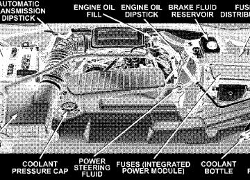
proper level, it should be added to the coolant bottle. Do not overfill. Points To Remember NOTE: When the vehicle is stopped after a few miles (a few kilometers) of operation, you may observe vapor coming from the front of the engine compartment. This is normally a result of moisture from rain, snow, or high humidity accumulating on the radiator and being vapor- ized when the thermostat opens, allowing hot coolant to enter the radiator. If an examination of your engine compartment shows no evidence of radiator or hose leaks, the vehicle may be safely driven. The vapor will soon dissipate. • Do not overfill the coolant recovery bottle.
MAINTAINING YOUR VEHICLE 385
• Check coolant freeze point in the radiator and in the coolant recovery bottle. If antifreeze needs to be added, contents of coolant recovery bottle must also be protected against freezing. • If frequent coolant additions are required, or if the level in the coolant recovery bottle does not drop when the engine cools, the cooling system should be pres- sure tested for leaks. • Maintain coolant concentration at 50% HOAT engine coolant (minimum) and distilled water for proper corrosion protection of your engine which contains aluminum components. • Make sure that the radiator and coolant recovery bottle overflow hoses are not kinked or obstructed. • Keep the front of the radiator clean. If your vehicle is equipped with air conditioning, keep the front of the condenser clean, also.
386 MAINTAINING YOUR VEHICLE
• Do not change the thermostat for summer or winter operation. If replacement is ever necessary, install ONLY the correct type thermostat. Other designs may result in unsatisfactory coolant performance, poor gas mileage, and increased emissions.
Emission Related Components
Fuel System Hoses And Vapor/Vacuum Harnesses When the vehicle is serviced for scheduled maintenance, inspect surface of hoses and nylon tubing for evidence of heat and mechanical damage. Hard and brittle rubber, cracking, checking, tears, cuts, abrasions, and excessive swelling suggest deterioration of the rubber. Particular attention should be given to examining hose surfaces nearest to high heat sources, such as the exhaust mani- fold. Insure nylon tubing in these areas has not melted or collapsed.
Inspect all hose clamps and couplings to make sure they are secure and no leaks are present. NOTE: Fluids such as oil, power steering fluid, and brake fluid are used during assembly plant operations to ease the assembly of hoses to couplings. Therefore, oil wetness at the hose-coupling area is not necessarily an indication of leakage. Actual dripping of hot fluid when systems are under pressure (during vehicle operation), should be noted before hose is replaced based on leakage. You are urged to use only the manufacturer’s specified hoses and clamps, or their equivalent in material and specification, in any fuel system servicing. It is manda- tory to replace all clamps that have been loosened or removed during service. Care should be taken in install- ing new clamps to insure they are properly torqued.
Positive Crankcase Ventilation (PCV) Valve Proper operation of the crankcase ventilation system requires that the PCV valve be free of sticking or plug- ging because of deposits. Deposits can accumulate in the PCV valve and passage with increasing mileage. Have the PCV valve, hoses, and passages checked for proper operation at the valve is plugged or sticking, replace with a new valve – Do not attempt to clean the PCV valve! Check ventilating hose for indication of damage or plugging with deposits. Replace if necessary. Brake System
the intervals specified.
If
Power Disc Brakes (Front and Rear) Disc brakes do not require adjustment; however, several hard stops during the break-in period are recommended to seat the linings and wear off any foreign material.
MAINTAINING YOUR VEHICLE 387
Brake Master Cylinders The fluid level in the master cylinders should be checked whenever the vehicle is serviced, or immediately if the brake system warning light is on. If necessary, add fluid to bring level to the full mark on the side of the reservoir of the brake master cylinder. Be sure to clean the top of the master cylinder area before removing the cap. With disc brakes, fluid level can be expected to fall as the brake pads wear. Brake fluid level should be checked when pads are replaced. If the brake fluid level is abnormally low, check system for leaks. Refer to Fluids, Lubricants and Genuine Parts for correct fluid type.
388 MAINTAINING YOUR VEHICLE
WARNING!
Use of brake fluid that may have a lower initial boiling point, or is unidentified, as to specifications may result in sudden brake failure during hard prolonged braking. You could have an accident.
WARNING!
Overfilling the brake fluid reservoir can result in spilling brake fluid on hot engine parts and the brake fluid catching on fire.
Use only brake fluid that has been in a tightly closed container to avoid contamination from foreign matter or moisture.
CAUTION!
Do not allow a petroleum-base fluid to contaminate the brake fluid. Seal damage may result.
Brake Hoses Inspection should be performed whenever the brake system is serviced or at intervals specified. Inspect hy- draulic brake hoses for surface cracking, scuffing or worn spots. If there is any evidence of cracking, scuffing, or worn spots, the hose should be replaced immediately! Eventual deterioration of the hose can take place with possible burst failure.
WARNING!
Worn brake hoses can burst and cause brake failure. You could have an accident. If you see any sign of cracking, scuffing, or worn spots, have the brake hoses replaced immediately.
Automatic Transmission
Fluid Level Check Check the fluid level while the transmission is at normal operating temperature 180°F (82°C). This occurs after at least 15 miles (24 km) of driving. At normal operating temperature the fluid cannot be held comfortably be- tween the fingertips. To check the automatic transmission fluid level properly, the following procedure must be used:
MAINTAINING YOUR VEHICLE 389
1. Operate the engine at idle speed and normal operating temperature. 2. The vehicle must be on level ground. 3. Fully apply the parking brake and press the brake pedal. 4. Place the gear selector momentarily in each gear position ending with the lever in P (Park). 5. Remove the dipstick, wipe it clean and reinsert it until seated. 6. Remove the dipstick again and note the fluid level on both sides. The fluid level should be between the “HOT” (upper) reference holes on the dipstick at normal operat- ing temperature. Verify that solid coating of oil is seen on both sides of the dipstick. If the fluid is low, add as required into the dipstick tube. Do not overfill. After adding any quantity of oil through the oil fill tube, wait
390 MAINTAINING YOUR VEHICLE
a minimum of two (2) minutes for the oil to fully drain into the transmission before rechecking the fluid level. If it is necessary to check the transmission below NOTE: the operating temperature, the fluid level should be between the two “COLD” (lower) holes on the dipstick with the fluid at approximately 70°F ( 21°C) (room temperature). If the fluid level is correctly established at room temperature, it should be between the “HOT” (upper) reference holes when the transmission reaches 180°F ( 82°C). Remember it is best to check the level at the normal operating temperature.
CAUTION!
Be aware that if the fluid temperature is below 50°F (10°C) it may not register on the dipstick. Do not add fluid until the temperature is elevated enough to produce an accurate reading.
7. Check for leaks. Release parking brake. To prevent dirt and water from entering the transmission after checking or replenishing fluid, make certain that the dipstick cap is properly reseated. It is normal for the dipstick cap to spring back slightly from its fully seated position, as long as its seal remains engaged in the dipstick tube. Automatic Transmission Fluid And Filter Change It is important that proper lubricant is used in the transmission. Refer to Fluids, Lubricants and Genuine Parts for correct fluid type. It is important that the transmission fluid be maintained at the prescribed level using the recommended fluid.
CAUTION!
Using a transmission fluid other than the manufac- turers recommended fluid may cause deterioration in transmission shift quality and/or torque converter shudder. Using a transmission fluid other than the manufacturers recommended fluid will result in more frequent fluid and filter changes. Refer to Fluids, Lubricants and Genuine Parts for correct fluid type.
Special Additives The manufacturer strongly recommends against the ad- dition of any additives to the transmission. Exception to this policy is the use of special dyes to aid in detecting fluid leaks. The use of transmission sealers should be avoided, since they may adversely affect seals.
MAINTAINING YOUR VEHICLE 391
Transfer Case Inspect the transfer case for fluid leaks. If a fluid leak is evident the transfer case fluid level may be low. Have the transfer case serviced immediately.
CAUTION!
Damage may result from operation of the vehicle with low transfer case fluid.
The transfer case fluid should be drained and refilled at the intervals specified. Lubricant Selection Refer to Fluids, Lubricants and Genuine Parts for correct fluid type.
392 MAINTAINING YOUR VEHICLE
Axles Refer to Fluids, Lubricants and Genuine Parts for correct fluid type. The manufacturer does not recommend regularly sched- uled oil changes for axles in vehicles whose operation is classified as normal truck service. NOTE: The presence of water in the gear lubricant will result in corrosion and possible failure of differential components. Operation of the vehicle in water, as may be encountered in some off-highway types of service, will require draining and refilling the axle to avoid damage. Rear Axle Rear Axle fluid levels should be 1/4⬙ (6.4 mm) +/- 1/4“ below the fill hole for 8 1/4⬙, and 9 1/4⬙ axles. Front Axle Front Axle fluid level should be 1/4” (6.4 mm) below the level of the fill hole.
Selection of Lubricating Grease The National Lubricating Grease Institute (NLGI) has developed a symbol (Certification Mark) to aid the vehicle owner in the proper selection of grease for chassis components. This symbol, an example shown below, is located on the grease container and identifies the appli- cation and quality of the grease.
are
There two groups identified, those for wheel bearings (Letter “G”) and those for chassis (Letter “L”) lubrication. Perfor- mance categories within these groups result in dual letter for each group. The letter des- ignations shown in the ex- ample the highest quality level available and when combined as shown can
designations
are
be used for chassis lubrication. Use only those greases that have the NLGI symbol on the container along with the proper quality level for your application. Appearance Care and Protection from Corrosion
Protection of Body and Paint from Corrosion Vehicle body care requirements vary according to geo- graphic locations and usage. Chemicals that make roads passable in snow and ice, and those that are sprayed on trees and road surfaces during other seasons, are highly corrosive to the metal in your vehicle. Outside parking, which exposes your vehicle to airborne contaminants, road surfaces on which the vehicle is operated, extreme hot or cold weather and other extreme conditions will have an adverse effect on paint, metal trim, and under- body protection. The following maintenance recommendations will enable you to obtain maximum benefit from the corrosion resistance built into your vehicle.
MAINTAINING YOUR VEHICLE 393
What Causes Corrosion? Corrosion is the result of deterioration or removal of paint and protective coatings from your vehicle. The most common causes are: • Road salt, dirt and moisture accumulation. • Stone and gravel impact. • Insects, tree sap and tar. • Salt in the air near seacoast localities. • Atmospheric fallout/industrial pollutants. Washing • Wash your vehicle regularly. Always wash your ve- hicle in the shade using a mild car wash soap, and rinse the panels completely with clear water. • If insects, tar or other similar deposits have accumu-
lated on your vehicle, wash it as soon as possible.
394 MAINTAINING YOUR VEHICLE
• Use Mopar威 auto polish to remove road film and stains and to polish your vehicle. Take care never to scratch the paint. • Avoid using abrasive compounds and power buffing that may diminish the gloss or thin out the paint finish.
CAUTION!
Do not use abrasive or strong cleaning materials such as steel wool or scouring powder, which will scratch metal and painted surfaces.
Special Care • If you drive on salted or dusty roads or if you drive near the ocean, hose off the undercarriage at least once a month.
• It is important that the drain holes in the lower edges of the doors, rocker panels and liftgate be kept clear and open. • If you detect any stone chips or scratches in the paint, touch them up immediately. The cost of such repairs is considered the responsibility of the owner. • If your vehicle is damaged due to an accident or similar cause which destroys the paint and protective coating have your vehicle repaired as soon as possible. The cost of such repairs is considered the responsibil- ity of the owner. • If you carry special cargo such as chemicals, fertilizers, de-icer salt, etc., be sure that such materials are well packaged and sealed. • If a lot of driving is done on gravel roads, consider
mud or stone shields behind each wheel.
• Use Mopar威 touch up paint on scratches as soon as possible. Your dealer has touch up paint to match the color of your vehicle.
Wheel and Wheel Trim Care All wheels and wheel trim, especially aluminum and chrome plated wheels should be cleaned regularly with a mild soap and water to prevent corrosion. To remove heavy soil, use Mopar威 Wheel Cleaner or select a non- abrasive, non-acidic cleaner. Do not use scouring pads, steel wool, a bristle brush or metal polishes. Only Mo- par威 cleaners are recommended. Do not use oven cleaner. Avoid automatic car washes that use acidic solutions or harsh brushes that may damage the wheels’ protective finish. YES Essentials威 Fabric Cleaning Procedure – If equipped YES Essentials威 seats may be cleaned in the following manner:
MAINTAINING YOUR VEHICLE 395
with a clean, dry towel.
• Remove as much of the stain as possible by blotting • Blot any remaining stain with a clean, damp towel. • For tough stains, apply Mopar威 Total Clean or a mild soap solution to a clean, damp cloth and remove stain. Use a fresh, damp towel to remove soap residue. • For grease stains, apply Mopar威 Multi-purpose cleaner to a clean, damp cloth and remove stain. Use a fresh, damp towel to remove soap residue. • Do not use any solvents or protectants on Yes Essen-
tials products.
Interior Care Use Mopar威 Fabric Cleaner to clean fabric upholstery and carpeting. Use Mopar威 Vinyl Cleaner to clean vinyl upholstery and trim.
396 MAINTAINING YOUR VEHICLE
Mopar威 Total Clean is specifically recommended for leather upholstery. Your leather upholstery can be best preserved by regular cleaning with a damp soft cloth. Small particles of dirt can act as an abrasive and damage the leather upholstery and should be removed promptly with a damp cloth. Stubborn soils can be removed easily with a soft cloth and Mopar威 Total Clean. Care should be taken to avoid soaking your leather upholstery with any liquid. Please do not use polishes, oils, cleaning fluids, solvents, deter- gents, or ammonia based cleaners to clean your leather upholstery. Application of a leather conditioner is not required to maintain the original condition.
WARNING!
Do not use volatile solvents for cleaning purposes. Many are potentially flammable, and if used in closed areas they may cause respiratory harm.
Cleaning Headlights Your vehicle has plastic headlights that are lighter and less susceptible to stone breakage than glass headlights. Plastic is not as scratch resistant as glass and therefore different lens cleaning procedures must be followed. To minimize the possibility of scratching the lenses and reducing light output, avoid wiping with a dry cloth. To remove road dirt, wash with a mild soap solution fol- lowed by rinsing. Do not use abrasive cleaning components, solvents, steel wool or other aggressive material to clean the lenses.
Glass Surfaces All glass surfaces should be cleaned on a regular basis with any commercial household-type glass cleaner. Never use an abrasive type cleaner. Use caution when cleaning inside rear windows equipped with electric defrosters or windshields equipped with a windshield wiper de-icer. Do not use scrapers or other sharp instru- ments which may scratch the elements. When cleaning the rear view mirror, spray cleaner on the towel or rag that you are using. Do not spray cleaner directly on the mirror. Cleaning Plastic Instrument Cluster Lenses The lenses in front of the instruments in this vehicle are molded in clear plastic. When cleaning the lenses, care must be taken to avoid scratching the plastic.
MAINTAINING YOUR VEHICLE 397
1. Clean with a wet soft rag. A mild soap solution may be used, but do not use high alcohol content or abrasive cleaners. If soap is used, wipe clean with a clean damp rag. 2. Dry with a soft tissue. Seat Belt Maintenance Do not bleach, dye or clean the belts with chemical solvents or abrasive cleaners. This will weaken the fabric. Sun damage will also weaken the fabric. If the belts need cleaning, use a mild soap solution or lukewarm water. Do not remove the belts from the car to wash them. Replace the belts if they appear frayed or worn or if the buckles do not work properly.
398 MAINTAINING YOUR VEHICLE
FUSE BLOCK
CAUTION!
When replacing a blown fuse, it is important to use only a fuse having the correct amperage rating. The use of a fuse with a rating other than indicated may result in a dangerous electrical system overload. If a properly rated fuse continues to blow, it suggests a problem in the circuit that must be corrected.
If you are leaving your vehicle dormant for NOTE: longer than 21 days you may want to take steps to protect your battery. You may do this by disconnecting the battery or by disconnecting the two ignition-off draw (I.O.D.) fuses located in the Auxiliary Power Distribution Center (PDC) located in the engine compartment. The I.O.D. cavities include a snap-in retainer that allows the fuse to be disconnected, without removing it from the fuse block. Pressing the I.O.D. fuse back into the cavity reconnects it. Fuses (Interior) The fuse block contains blade-type mini-fuses, relays, and circuit breakers for high-current circuits. It is located in the left kick panel. It is accessible through a snap-in cover.
MAINTAINING YOUR VEHICLE 399
400 MAINTAINING YOUR VEHICLE
Cavity
Mini Fuse/Color
Description
F1
F 2
15 Amp Blue
10 Amp Red
Instrument Clus- ter Battery Feed
Spare
F3
10 Amp Red
Ignition Run/ Start for Next
Generation Con- troller (NGC),
Integrated
Power Module (IPM), AC Relay and Fuel Pump
Relay
F4
10 Amp Red
Door Node and Non-Memory Power Mirror Switch Battery
Feed
F5
F6
F7
F8
F9
F10
(2) 10 Amp Red
2 Amp Clear
25 Amp Natural
Airbags (2 Fuses
in Yellow Holder)
Ignition Run/ Start Unlock Radio Battery
Feed
10 Amp Red
10 Amp Red
10 Amp Red
Ignition Run/
Start for
Cluster/Transfer Case/Seat Sw. Back lighting Satellite Digital Audio Receiver (SDAR)/Digital
Video Disc
(DVD) Battery
Feed Spare
F11
F12
F13
F14
F15
F16
10 Amp Red Heated Mirrors 20 Amp Yellow Cluster Battery Ignition Run
Feed
10 Amp Red
10 Amp Red
15 Amp Blue
HVAC Module/
Heated Rear
Glass (EBL) Re-
lay
ABS Module Ig-
nition Run Battery Feed Blue Tooth,
Compass/Trip
Computer
(CMTC), Sentry Key Diagnostics 20 Amp Yellow Reconfigurable Power Outlets
MAINTAINING YOUR VEHICLE 401
20 Amp Yellow
20 Amp Yellow
Ignition Run / Rear Park Assist / Second Row Heated Seats Cigar Lighter
Ignition
10 Amp Red
Spare Fuse
15 Amp Blue
Heating & Air Conditioning w/ATC Only Battery Feed 25 Amp Natural Amplifier Bat-
tery Feed
F17
F18
F19
F20
F21
402 MAINTAINING YOUR VEHICLE
Fuses (Power Distribution Center)
Power Distribution Center
Your vehicle is equipped with an electrical power distri- bution center located in the left side of the engine compartment. This center contains cartridge fuses, mini fuses and relays. A description of each fuse and component may be
stamped on the inside cover otherwise the cavity number of each fuse is stamped on the inside cover that corre- sponds to the following chart. These fuses and relays can be obtained from your dealer.
Cavity
Cartridge
Fuse / Relay 30 Amp Pink 30 Amp Pink 40 Amp Green 30 Amp Pink 40 Amp Green 30 Amp Pink
Mini Fuse
Description
Starter
Front Wiper
Brake Batt
JB Feed Acc # 2
Power Seats
Run Remote Relay Feed
Cavity
10
11
12
13
14
Cartridge
Fuse / Relay 40 Amp Green 40 Amp Green Spare 30 Amp Pink 40 Amp Green 40 Amp Green
30 Amp Pink 40 Amp Green
Mini Fuse
Description
Cavity
Blower Motor Relay Feed JB Feed Acc Delay
ASD
Power Liftgate ( If Equipped) JB Feed / Heated Rear Glass (EBL)/ T Case Brake JB Feed RR
ESP Pump
15
16
17
1819
20
21
22
Cartridge
Fuse / Relay 50 Amp Red
MAINTAINING YOUR VEHICLE 403
Mini Fuse
10 Amp Red Spare 20 Amp Yellow 20 Amp Yellow 25 Amp Clear 20 Amp Yellow 20 Amp Yellow
Description
JB Feed
Spare
Fuel Pump
Next Generation Con- troller (NGC) 115v Power Inverter
ABS Batt
Next Generation Con- troller (NGC) Batt
404 MAINTAINING YOUR VEHICLE
Cavity
Cartridge
Fuse / Relay
Mini Fuse
20 Amp Yellow 15 Amp Blue 15 Amp Blue Spare 20 Amp Yellow Spare
Description
Cavity
Cartridge
Fuse / Relay
Mini Fuse
Trailer Tow
A/C Clutch
Stop Lamp Switch
Run/Start Relay Feed
33
34
35
36
37
38
39
40Relay
Relay Relay Spare Relay Spare Relay Relay
Description
Electronic Automatic Transaxle (EATX) AC Clutch Fuel Pump Rly
Stop Lamp Switch
Blower Motor Auto Shut Down (ASD) Rly
Relay Relay Spare Relay
Run Start Run Remote
Starter
23
24
25
26
2728
29
30
31
32Fuses (Integrated Power Module)
Integrated Power Module
An integrated Power Module is located in the left side of the engine compartment. This center contains cartridge fuses, mini fuses and relays. A description of each fuse and component may be stamped on the inside cover
MAINTAINING YOUR VEHICLE 405
otherwise the cavity number of each fuse is stamped on the inside cover that corresponds to the following chart.
Cavity
Cartridge
Fuse / Relay
Mini Fuse
Description
Relay Relay Relay Relay Relay
Relay
Relay
10
10 Amp Red 10 Amp Red 10 Amp Red
Wiper On/Off Rly Wiper Hi/Lo Rly Horn Rly Rear Wiper Rly Lt Trailer-Tow Stop/ Turn Rly Rt Trailer-Tow Stop/ Turn Rly Park Lamps Rly Lt Park Lamps
Trailer-Tow Park Lamps Rt Park Lamps
406 MAINTAINING YOUR VEHICLE
Cartridge
Fuse / Relay
Relay
Cavity
11
1213
14
15
16
17
18
19
Mini Fuse
Description
Cavity
20 Amp Yel- low 20 Amp Yel- low 20 Amp Yel- low 20 Amp Yel- low 20 Amp Yel- low 20 Amp Yel- low 20 Amp Yel- low 20 Amp Yel- low
Radiator Fan Hi Rly Front Control Module (FCM) Batt #4
Front Control Module (FCM) Batt #2
Adjustable PedalFt Fog Lamps
Horn
Rear Wiper
Front Control Module (FCM) Batt #1
Lt Trailer-Tow Stop/ Turn20
21
22
23
24
25
26
2728
29
30Cartridge
Fuse / Relay
30 Amp Pink 40 Amp Green Relay Relay Relay
Mini Fuse
Description
20 Amp Yel- low 20 Amp Yel- low
30 Amp Green 30 Amp Green
Front Control Module (FCM) Batt #3
Rt Trailer-Tow Stop/ Turn Front Control Module (FCM) BATT # 5
Radiator FanRadiator Fan Lo Rly Ft Fog Lamps Rly Adjustable Pedal Rly Ignition Off Draw (IOD) #1
Ignition Off Draw (IOD) #2
Spare SpareVEHICLE STORAGE If you are storing your vehicle for more than 21 days, we recommend that you take the following steps to mini- mize the drain on your vehicle’s battery: • Disconnect the Ignition-Off Draw fuse (I.O.D.) fuse located in the Power Distribution Center (PDC). The I.O.D. cavity includes a snap-in retainer that allows the fuse to be disconnected, without removing it from the fuse block. • The transfer case should be placed in the 4HI mode and kept in this position to minimize the battery drain. • As an alternative to the above steps you may discon-
nect the negative cable from the battery.
MAINTAINING YOUR VEHICLE 407
REPLACEMENT LIGHT BULBS
LIGHT BULBS — Interior Bulb No. Dome Light . . . . . . . . . . . . . . . . . . . . . . . . WL212–2
Liftgate Lamp . . . . . . . . . . . . . . . . . . . . . . . . . . . 567
Overhead Console Lights . . . . . . . . . . . . . PLW214–2A Reading Light . . . . . . . . . . . . . . . . . . . . . . . WL212–2
Visor Vanity Lights . . . . . . . . . . . . . . . Not ServiceableLIGHT BULBS — Outside Bulb No. Headlight . . . . . . . . . . . . . . . . . . . . . . . . . . . . . H13
Front Park/Turn . . . . . . . . . . . . . . . . . . . . . . 3457AK Back-Up . . . . . . . . . . . . . . . . . . . . . . . . . . . . . . 3057
Center High Mounted Stoplight . . . . . . . . . . . . . . 921
Front Side Marker . . . . . . . . . . . . . . . . . . . . . . . . 168
Fog Lamp . . . . . . . . . . . . . . . . . . . . . . . . . . . 9006LL License Plate Light . . . . . . . . . . . . . . . . . . . . . . . 168
Rear Tail, Stop, Turn Signal and Side Marker . . . . 3057408 MAINTAINING YOUR VEHICLE
BULB REPLACEMENT
Headlights/Parking/Turn Signal
1. Remove the two bolts attaching the headlight to the upper fender reinforcement (hood must be open to access bolts).
2. Remove one nut that attaches the headlight to the inner fender panel. Access to the nut is possible by opening the fender panel access door which is located in the wheel liner.
3. Grasp the headlight and pull firmly to disengage the headlight from the fender panel.
4. While firmly holding the headlight in your hands disconnect all connectors by following the procedure described in step number 5 below. 5. Remove the bulb connector from the headlight making sure to pull and release the red tab on all connectors. Loosen the connector by pressing down on the black and/or green release which is located below or above the red tab. The green release is located above the red tab on the H13, the black release is located above the 3457AK red tab. 6. Twist and remove socket from lamp. 7. Remove bulb from socket and replace. NOTE: These are Halogen bulbs. Take care not to touch the bulb with your fingers. Body oils from your fingers could cause excessive heat build-up which reduces bulb life.
MAINTAINING YOUR VEHICLE 409
Rear Side Marker, Tail Lights, Turn Signals And Backup Lights — Replacement
1. Remove the two push-pins from the tail light housing.
410 MAINTAINING YOUR VEHICLE
2. Rotate the light to the outboard side of the vehicle and remove.
3. Unlock and remove electrical connector.
MAINTAINING YOUR VEHICLE 411
4. Remove the three screws holding the bulb strip to the back of the tail lamp.
412 MAINTAINING YOUR VEHICLE
5. Remove the bulb strip from the tail light lens.
6. Remove bulbs from bulb strip by pulling the bulb straight out.
MAINTAINING YOUR VEHICLE 413
License Lights
1. Remove the two screws securing the lens to the liftgate.
414 MAINTAINING YOUR VEHICLE
2. Rotate the socket 1/4 turn counterclockwise.
Center High-Mounted Stoplight
1. Remove two screws securing stoplight housing assem- bly to the liftgate.
3. Pull bulb from socket.
2. Turn socket 1/4 counterclockwise and free from hous- ing.
Fog Lights
MAINTAINING YOUR VEHICLE 415
3. Pull bulb straight from socket to remove.
1 – (3) Wheel liner screws 2 – (1) Air dam screw
416 MAINTAINING YOUR VEHICLE
To replace the left foglamp bulb: 1. Remove the three wheel liner screws 2. Remove the remove the far left air dam screw at the bottom of the fascia. 3. Peel back the liner and access the foglamp 4. Rotate the socket and connector 1/4 turn counter- clockwise and pull straight reward to disengage from the lamp.
5. Remove the bulb from the socket and replace. The right foglamp can be accessed from below the vehicle. Follow the previous steps 4 and 5 of the left foglamp to replace the bulb. NOTE: These are Halogen bulbs. Take care not to touch the bulb with your fingers. Body oils from your fingers could cause excessive heat build-up, which reduces bulb life.
FLUIDS AND CAPACITIES
Fuel
MAINTAINING YOUR VEHICLE 417
U.S.
Metric
3.7L/4.7L, 87 Octane
5.7L, 89 Octane
Engine Oil (with filter)
3.7L, SAE 5W-20, API Certified 4.7L, SAE 5W-20, API Certified 5.7L, SAE 5W-20, API Certified Cooling System (includes 2.1 Qts./2L for coolant bottle 3.7L without Rear Heat (Mopar威 Antifreeze/Coolant 5 Year/100,000 Mile Formula)
3.7L with Rear Heat (Mopar威 Antifreeze/Coolant 5 Year/100,000 Mile Formula)
4.7L without Rear Heat (Mopar威 Antifreeze/Coolant 5 Year/100,000 Mile Formula)
4.7L with Rear Heat (Mopar威 Antifreeze/Coolant 5 Year/100,000 Mile Formula)
5.7L without Rear Heat (Mopar威 Antifreeze/Coolant 5 Year/100,000 Mile Formula)
5.7L with Rear Heat (Mopar威 Antifreeze/Coolant 5 Year/100,000 Mile Formula)
NOTE: All fluid capacities are approximate.
27 Gal. 27 Gal
5 Qt. 6 Qt. 7 Qt.
13.5 Qt. 14.5 Qt. 13.1 Qt. 14.2 Qt.
NA
16.6 Qt.
102L 102L
4.7L 5.7L 6.6L
12.9L 13.8L 12.5L 13.5L NA 15.8L
418 MAINTAINING YOUR VEHICLE
FLUIDS, LUBRICANTS AND GENUINE PARTS
Engine Component Engine Coolant
3.7/4.7L Engine Oil
5.7L Engine Oil
Engine Oil Filter Spark Plugs
Fuel Selection 3.7L/4.7L Fuel Selection 5.7L
Fluids, Lubricants and Genuine Parts Mopar威 Antifreeze/Coolant 5 Year/100,000 Mile Formula HOAT (Hybrid Or- ganic Additive Technology) or equivalent. Use SAE 5W-20, API Certified, meeting material standard MS-6395 or equiva- lent. Use SAE 5W-20, API Certified, meeting material standard MS-6395 or equiva- lent. Mopar威 Engine Oil Filter, P/N 5281090 or equivalent. Refer to the Vehicle Emission Control Information label in the engine com- partment. 87 Octane, (R+M)/2 Method 89 Octane, (R+M)/2 Method
MAINTAINING YOUR VEHICLE 419
Chassis Component Automatic Transmission Transfer Case Front Axle Rear Axle Brake Master Cylinder
Power Steering Reservoir
Fluids, Lubricants and Genuine Parts. Mopar威 ATF+4, Automatic Transmission Fluid. Mopar威 ATF+4, Automatic Transmission Fluid. SAE 75W-90 Multipurpose Type, GL-5 Gear Lubricant or equivalent. SAE 75W-140 Synthetic Gear Lubricant or equivalent. Mopar威 DOT 3 and SAE J1703 should be used or equivalent. If DOT 3
brake fluid is not available, then DOT 4 is acceptable. Use only recom- mended brake fluids. Mopar威 ATF+4, Automatic Transmission Fluid.MAINTENANCE SCHEDULES
CONTENTS
䡵 Emission Control System Maintenance . . . . . . . . 422
䡵 Maintenance Schedules . . . . . . . . . . . . . . . . . . . 422▫ Schedule “B” . . . . . . . . . . . . . . . . . . . . . . . . 425
▫ Schedule “A” . . . . . . . . . . . . . . . . . . . . . . . . 440M
422 MAINTENANCE SCHEDULES
EMISSION CONTROL SYSTEM MAINTENANCE The “Scheduled” maintenance services, listed in bold type on the following pages must be done at the times or mileages specified to assure the continued proper func- tioning of the emission control system. These, and all other maintenance services included in this manual, should be done to provide best vehicle performance and reliability. More frequent maintenance may be needed for vehicles in severe operating conditions such as dusty areas and very short trip driving. Inspection and service also should be done any time a malfunction is suspected. NOTE: Maintenance, replacement, or repair of the emis- sion control devices and systems on your vehicle may be performed by any automotive repair establishment or individual using any automotive part which has been certified pursuant to U.S. EPA or, in the State of Califor- nia, California Air Resources Board regulations.
MAINTENANCE SCHEDULES There are two maintenance schedules that show the required service for your vehicle. First is Schedule “B”. It is for vehicles that are operated under the conditions that are listed below and at the beginning of the schedule. • Day or night temperatures are below 32° F (0° C). • Stop and go driving. • Extensive engine idling. • Driving in dusty conditions. • Short trips of less than 10 miles (16 km). • More than 50% of your driving is at sustained high • Trailer towing. • Taxi, police, or delivery service (commercial service).
speeds during hot weather, above 90° F (32° C).
• Off-road or desert operation. • If equipped for and operating with E-85 (ethanol)
fuel.
If ANY of these apply to you then change your NOTE: engine oil every 3,000 miles (5 000 km) or 3 months, whichever comes first and follow schedule “B” of the ⬙Maintenance Schedules⬙ section of this manual. If ANY of these apply to you then change your NOTE: coolant every 102,000 miles (170 000 km) or 60 months, whichever comes first and follow schedule “B” of the ⬙Maintenance Schedules⬙ section of this manual. NOTE: Most vehicles are operated under the conditions listed for Schedule ⬙B⬙.
MAINTENANCE SCHEDULES 423
Second is Schedule “A”. It is for vehicles that are not operated under any of the conditions listed under Sched- ule ⬙B⬙. Use the schedule that best describes your driving condi- tions. Where time and mileage are listed, follow the interval that occurs first. NOTE: Under no circumstances should oil change in- tervals exceed 6000 miles (10 000 km) or 6 months whichever comes first.
CAUTION!
Failure to perform the required maintenance items may result in damage to the vehicle.
424 MAINTENANCE SCHEDULES
At Each Stop for Fuel • Check the engine oil level about 5 minutes after a fully warmed engine is shut off. Checking the oil level while the vehicle is on level ground will improve the accu- racy of the oil level reading. Add oil only when the level is at or below the ADD or MIN mark. • Check the windshield washer solvent and add if
required.
damage.
Once a Month • Check tire pressure and look for unusual wear or • Inspect the battery and clean and tighten the terminals • Check the fluid levels of coolant reservoir, brake master cylinder, and transmission and add as needed. • Check all lights and all other electrical items for correct
as required.
operation.
At Each Oil Change • Change the engine oil filter. • Inspect the exhaust system. • Inspect the brake hoses. • Inspect the CV joints (if equipped) and front suspen- • Check the automatic transmission fluid level. • Check the coolant level, hoses, and clamps.
sion components.
SCHEDULE “B” 425
Schedule “B” Follow schedule “B” if you usually operate your vehicle under one or more of the following conditions. • Day or night temperatures are below 32° F (0° C). • Stop and go driving. • Extensive engine idling. • Driving in dusty conditions. • Short trips of less than 10 miles (16 km). • More than 50% of your driving is at sustained high • Trailer towing. • Taxi, police, or delivery service (commercial service). • Off-road or desert operation.
speeds during hot weather, above 90° F (32° C).
426 SCHEDULE “B”
• If equipped for and operating with E-85 (ethanol)
fuel.
If ANY of these apply to you then change your NOTE: engine oil every 3,000 miles (5 000 km) or 3 months, whichever comes first and follow schedule “B” of the
⬙Maintenance Schedules⬙ section of this manual. If ANY of these apply to you then change your NOTE: coolant every 102,000 miles (170 000 km) or 60 months, whichever comes first and follow schedule “B” of the ⬙Maintenance Schedules⬙ section of this manual.
3,000
(5 000)Miles (Kilometers) Change engine oil and engine oil filter, or at 3
months whichever comes first. Rotate tires. Check spare tire for proper pressure and correct stowage. Change rear axle fluid. Change front axle fluid (4X4). Inspect engine air cleaner filter, replace if neces- sary.SCHEDULE “B” 427
6,000
(10 000)9,000
(15 000)12,000
(20 000)15,000
(25 000)M
428 SCHEDULE “B”
Miles (Kilometers) Change engine oil and engine oil filter, or at 3
months whichever comes first. Rotate tires. Check spare tire for proper pressure and correct stowage. Change rear axle fluid. Change front axle fluid (4X4). Check transfer case fluid level (4X4). Inspect brake linings. Inspect engine air cleaner filter, replace if neces- sary. Replace spark plugs. Inspect PCV valve, replace as necessary.*18,000
(30 000)21,000
(35 000)27,000
(45 000)24,000
(40 000)30,000
(50 000)Miles (Kilometers) Change engine oil and engine oil filter, or at 3
months whichever comes first. Rotate tires. Check spare tire for proper pressure and correct stowage. Change rear axle fluid. Change front axle fluid (4X4). Inspect brake linings. Inspect engine air cleaner filter, replace if neces- sary.33,000
(55 000)39, 000
(65 000)36,000
(60 000)SCHEDULE “B” 429
42,000
(70 000)45,000
(75 000)M
430 SCHEDULE “B”
Miles (Kilometers) Change engine oil and engine oil filter, or at 3
months whichever comes first. Rotate tires. Check spare tire for proper pressure and correct stowage. Change rear axle fluid. Change front axle fluid (4X4). Inspect brake linings. Inspect engine air cleaner filter, replace if neces- sary. Replace spark plugs. Inspect PCV valve, replace as necessary.* Inspect auto tension drive belt and replace if re- quired.51,000
(85 000)48,000
(80 000)57,000
(95 000)54,000
(90 000)60,000
(100 000)Miles (Kilometers) Drain and refill automatic transmission fluid, change filter (3.7L). This applies only if your ve- hicle is used for police, taxi, fleet, or frequent trailer towing. Drain and refill automatic transmission fluid and change main sump filter (4.7L/5.7L only). This ap- plies only if your vehicle is used for police, taxi, fleet, or frequent trailer towing. Inspect transfer case fluid (4X4). Flush and replace engine coolant at 60 months, or 102, 000 miles (170 000 km) whichever comes first.
SCHEDULE “B” 431
48,000
(80 000)51,000
(85 000)54,000
(90 000)57,000
(95 000)60,000
(100 000)M
432 SCHEDULE “B”
Miles (Kilometers) Change engine oil and engine oil filter, or at 3
months whichever comes first. Rotate tires. Check spare tire for proper pressure and correct stowage. Change rear axle fluid. Change front axle fluid (4X4). Inspect brake linings. Inspect engine air cleaner filter, replace if neces- sary. Inspect auto tension drive belt and replace if re- quired.63,000
(105 000)66,000
(110 000)69,000
(115 000)72,000
(120 000)75,000
(125 000)Miles (Kilometers ) Change engine oil and engine oil filter, or at 3
months whichever comes first. Rotate tires. Check spare tire for proper pressure and correct stowage. Change rear axle fluid. Change front axle fluid (4X4). Check transfer case fluid level (4X4). Inspect brake linings. Inspect engine air cleaner filter, replace if neces- sary. Replace spark plugs. Inspect PCV valve, replace as necessary.* Inspect auto tension drive belt and replace if re- quired.78,000
(130 000)81,000
(135 000)84,000
(140 000)87,000
(145 000)90,000
(150 000)SCHEDULE “B” 433
434 SCHEDULE “B”
Miles (Kilometers) Change engine oil and engine oil filter, or at 3 months whichever comes first. Rotate tires. Check spare tire for proper pressure and correct stowage. Flush and replace engine coolant, if not replaced at 60
months. Change rear axle fluid. Change front axle fluid (4X4).93,000
(155 000)99,000
(165 000)102,000
(170 000)96,000
(160 000)Miles (Kilometers) Change engine oil and engine oil filter, or at 3
months whichever comes first. Rotate tires. Check spare tire for proper pressure and cor- rect stowage. Change rear axle fluid. Change front axle fluid (4X4). Inspect brake linings. Inspect engine air cleaner filter, replace if necessary. Replace spark plugs. Inspect PCV valve, replace as necessary.* Inspect auto tension drive belt and replace if required. Drain and refill transfer case fluid (4X4).105,000
(175 000)108,000
(180 000)111,000
(185 000)114,000
(190 000)117,000
(195 000)120,000
(200 000)SCHEDULE “B” 435