- 2011 Dodge Durango Owners Manuals
- Dodge Durango Owners Manuals
- 2008 Dodge Durango Owners Manuals
- Dodge Durango Owners Manuals
- 2009 Dodge Durango Owners Manuals
- Dodge Durango Owners Manuals
- 2007 Dodge Durango Owners Manuals
- Dodge Durango Owners Manuals
- 2004 Dodge Durango Owners Manuals
- Dodge Durango Owners Manuals
- 2013 Dodge Durango Owners Manuals
- Dodge Durango Owners Manuals
- 2005 Dodge Durango Owners Manuals
- Dodge Durango Owners Manuals
- 2006 Dodge Durango Owners Manuals
- Dodge Durango Owners Manuals
- 2012 Dodge Durango Owners Manuals
- Dodge Durango Owners Manuals
- Download PDF Manual
-
stop as soon as possible, check the inflation pressure of each tire on your vehicle, and inflate each tire to the pressure recommended by the vehicle manufacturer. The system will automatically update and the TPM warning lamp will extinguish once the updated tire pressures have been received. The vehicle may need to be driven for up to 10 minutes above 15 mph (25 kph) to receive this information. A low spare tire will not cause the Tire Pressure Moni- toring Telltale Lamp to illuminate or the chime to sound. The Tire Pressure Monitoring Telltale Lamp will flash on and off for 60 seconds, and an audible chime will sound
308 STARTING AND OPERATING
when a system fault is detected. The flash cycle will repeat every ten minutes, without an audible chime, until the fault condition no longer exists. If the ignition key is cycled, this sequence will repeat, providing the system fault still exists. NOTE: A non-matching or compact spare wheel and tire assembly does not have a tire pressure monitoring sensor; therefore, it will not be monitored by the Tire Pressure Monitor System (TPMS). If the non-matching or compact spare tire was used in place of one of the four road tires, a system fault will occur while driving the vehicle. In case of a low pressure condition (ie. flat tire), the “Tire Pressure Monitoring Telltale Light” will remain on solid until the original road tire has been properly repaired, and put back onto the vehicle in place of the non-matching or compact spare tire.
CAUTION!
The TPMS has been optimized for the original equipment tires and wheels. TPMS pressures have been established for the tire size equipped on your vehicle. Undesirable system operation or sensor damage may result when using replacement equip- ment that is not of the same size, type, and/or style. After-market wheels can cause sensor damage. Do not use tire sealant from a can, or balance beads if your vehicle is equipped with a TPMS, as damage to the sensors may result.
CAUTION!
After inspecting or adjusting the tire pressure al- ways reinstall the valve stem cap. This will prevent moisture and dirt from entering the valve stem, which could damage the wheel rim sensor.
NOTE: • The TPMS is not intended to replace normal tire care and maintenance, or to provide warning of a tire failure or condition. • The TPMS should not be used as a tire pressure gauge • Driving on a significantly under-inflated tire causes the tire to overheat and can lead to tire failure. Under-inflation also reduces fuel efficiency and tire tread life, and may affect the vehicle’s handling and stopping ability.
while adjusting your tire pressure.
STARTING AND OPERATING 309
• The TPMS is not a substitute for proper tire mainte- nance, and it is the driver’s responsibility to maintain correct tire pressure, even if under-inflation has not reached the level to trigger illumination of the Tire Pressure Monitoring Telltale lamp.
General Information This device complies with part 15 of the FCC rules and RSS 210 of Industry Canada. Operation is subject to the following conditions: • This device may not cause harmful interference. • This device must accept any interference received, including interference that may cause undesired op- eration.
The tire pressure sensors are covered under one of the following licenses:
United States . . . . . . . . . . . . . . . . . . . . . KR5S120123
Canada . . . . . . . . . . . . . . . . . . . . . . . . 2671-S120123310 STARTING AND OPERATING
FUEL REQUIREMENTS
All engines (except 5.7L engines) are de- signed to meet all emissions regulations and provide excellent fuel economy and performance when using high quality un- leaded “regular” gasoline having an oc- tane rating of 87. The routine use of pre- mium gasoline is not recommended. Under normal conditions the use of premium fuel will not provide a benefit over high quality regular gasolines and in some circumstances may result in poorer performance.
The 5.7L engine is designed to meet all emissions regulations and provide satisfac- tory fuel economy and performance when using high quality unleaded gasoline hav- ing an octane range of 87 to 89. The manu- facturer recommends the use of 89 octane for optimum performance.The routine use of premium gasoline is not recommended. The use of premium
gasoline will provide no benefit over high quality regular and mid-grade gasolines, and in some circumstances may result in poorer performance. Light spark knock at low engine speeds is not harmful to your engine. However, continued heavy spark knock at high speeds can cause damage and immediate service is required. Poor quality gasoline can cause problems such as hard starting, stalling and hesitations. If you experience these symptoms, try another brand of “regular” gasoline be- fore considering service for the vehicle. Over 40 auto manufacturers world-wide have issued and endorsed consistent gasoline specifications (the World- wide Fuel Charter, WWFC) to define fuel properties necessary to deliver enhanced emissions, performance and durability for your vehicle. We recommend the use of gasolines that meet the WWFC specifications if they are available.
Reformulated Gasoline Many areas of the country require the use of cleaner burning gasoline referred to as “Reformulated Gasoline.” Reformulated gasolines contain oxygenates, and are spe- cifically blended to reduce vehicle emissions and im- prove air quality. We strongly support the use of reformulated gasolines. Properly blended reformulated gasolines will provide excellent performance and durability for the engine and fuel system components. Gasoline/Oxygenate Blends Some fuel suppliers blend unleaded gasoline with oxy- genates such as 10% ethanol, MTBE and ETBE. Oxygen- ates are required in some areas of the country during the winter months to reduce carbon monoxide emissions. Fuels blended with these oxygenates may be used in your vehicle.
STARTING AND OPERATING 311
CAUTION!
DO NOT use gasoline containing Methanol or E85
Ethanol. Use of these blends may result in starting and driveability problems and may damage critical fuel system components.4.7L Engine — If Equipped , is now rated for NOTE: E85 Ethanol use. Only vehicles with the E-85 fuel filler door label can operate on E-85. For more information, refer to “Flexible Fuel” in this section. Problems that result from using methanol/gasoline or E85 Ethanol blends are not the responsibility of the manufacturer. While MTBE is an oxygenate made from Methanol, it does not have the negative effects of Metha- nol.
312 STARTING AND OPERATING
MMT In Gasoline MMT is a manganese-containing metallic additive that is blended into some gasoline to increase octane. Gasolines blended with MMT provide no performance advantage beyond gasolines of the same octane number without MMT. Gasolines blended with MMT reduce spark plug life and reduce emission system performance. We recom- mend that gasolines free of MMT be used in your vehicle. The MMT content of gasoline may not be indicated on the gasoline pump; therefore, you should ask your gaso- line retailer whether or not his/her gasoline contains MMT.
It is even more important to look for gasolines without MMT in Canada because MMT can be used at levels higher than allowed in the United States. MMT is pro- hibited in Federal and California reformulated gasolines. Materials Added To Fuel All gasolines sold in the United States are required to contain effective detergent additives. Use of additional detergents or other additives is not needed under normal conditions and would result in unnecessary cost. There- fore, you should not have to add anything to the fuel.
Fuel System Cautions
CAUTION!
STARTING AND OPERATING 313
NOTE: systems can result against you.
Intentional tampering with emissions control in civil penalties being assessed
Follow these guidelines to maintain your vehicle’s performance:
• The use of leaded gas is prohibited by Federal law. Using • An out-of-tune engine, or certain fuel or ignition malfunctions,
leaded gasoline can impair engine performance, damage the emission control system.
can cause the catalytic converter to overheat. If you notice a pungent burning odor or some light smoke, your engine may be out of tune or malfunctioning and may require immediate service. Contact your dealer for service assistance.
• When pulling a heavy load or driving a fully loaded vehicle
when the humidity is low and the temperature is high, use a premium unleaded fuel to help prevent spark knock. If spark knock persists, lighten the load, or engine piston damage may result.
• The use of fuel additives which are now being sold as octane
enhancers is not recommended. Many of these products con- tain high concentrations of methanol. Fuel system damage or vehicle performance problems resulting from the use of such fuels or additives is not the responsibility of the manufacturer.
314 STARTING AND OPERATING
Carbon Monoxide Warnings
WARNING!
Carbon monoxide (CO) in exhaust gases is deadly. Follow the precautions below to prevent carbon monoxide poisoning:
• Do not inhale exhaust gases. They contain carbon monoxide, a
colorless and odorless gas which can kill. Never run the engine in a closed area, such as a garage, and never sit in a parked vehicle with the engine running for an extended period. If the vehicle is stopped in an open area with the engine running for more than a short period, adjust the ventilation system to force fresh, outside air into the vehicle.
• Guard against carbon monoxide with proper maintenance.
Have the exhaust system inspected every time the vehicle is raised. Have any abnormal conditions repaired promptly. Until repaired, drive with all side windows fully open.
• Keep the liftgate closed when driving your vehicle to prevent
carbon monoxide and other poisonous exhaust gases from entering the vehicle.
ADDING FUEL
Fuel Filler Cap (Gas Cap)
The gas cap is behind the fuel filler door. If the gas cap is lost or damaged, be sure the replacement cap is for use with this vehicle. NOTE: To avoid contact between fuel cap and paint, hang tether strap over hook provided on inner fuel door.
CAUTION!
Damage to the fuel system or emission control system could result from using an improper fuel tank filler tube cap (gas cap). A poorly fitting cap could let impurities into the fuel system.
CAUTION!
A poorly fitting gas cap may cause the Malfunction Indicator Light to turn on.
CAUTION!
To avoid fuel spillage and overfilling, do not “top off” the fuel tank after filling.
NOTE: When the fuel nozzle “clicks” or shuts off, the fuel tank is full.
STARTING AND OPERATING 315
WARNING!
• Never have any smoking materials lit in or near the vehicle when the gas cap is removed or the tank filled. • Never add fuel when the engine is running. This is in violation of most state and federal fire regulations and will cause the malfunction indi- cator light to turn on.
NOTE: Tighten the gas cap about 1/4 turn until you hear one click. This is an indication that cap is properly tightened. If the gas cap is not tighten properly, the Malfunction Indicator Light will come on. Be sure the gas cap is tightened every time the vehicle is refueled.
316 STARTING AND OPERATING
WARNING!
A fire may result if gasoline is pumped into a portable container that is inside of a vehicle. You could be burned. Always place gas containers on the ground while filling.
Loose Fuel Filler Cap Message After fuel is added, the vehicle diagnostic system can determine if the fuel filler cap is loose, improperly installed, or damaged. A loose fuel filler cap message will be displayed in the instrument cluster. Tighten the gas cap until a ⬙clicking⬙ sound is heard. This is an indication that the gas cap is properly tightened. Press the odometer reset button to turn the message off. If the problem persists, the message will appear the next time the vehicle is started. This might indicate a damaged cap. If
the problem is detected twice in a row, the system will turn on the Malfunction Indicator Light (MIL). Resolving the problem will turn the MIL light off.
CAUTION!
Damage to the fuel system or emission control system could result from using an improper fuel tank filler cap (gas cap). A poorly fitting cap could let impurities into the fuel system.
WARNING!
• Never add fuel when the engine is running. • Never have any smoking materials lit in or near the vehicle when the fuel cap is removed or the tank filled.
FLEXIBLE FUEL
E-85 General Information The information in this section is for Flexible Fuel ve- hicles only. These vehicles can be identified by the unique fuel filler door label that states Ethanol (E-85) or Un- leaded Gasoline Only. This section only covers those subjects that are unique to these vehicles. Please refer to the other sections of this manual for information on features that are common between Flexible Fuel and gasoline only powered vehicles.
STARTING AND OPERATING 317
CAUTION!
Only vehicles with the E-85 fuel filler door label can operate on E-85.
ETHANOL FUEL (E-85) E-85 is a mixture of approximately 85% fuel ethanol and 15% unleaded gasoline.
WARNING!
Ethanol vapors are extremely flammable and could cause serious personal injury. Never have any smok- ing materials lit in or near the vehicle when remov- ing the fuel filler tube cap (gas cap) or filling the tank. Do not use E-85 as a cleaning agent and never use it near an open flame.
318 STARTING AND OPERATING
Fuel Requirements Your vehicle will operate on both unleaded gasoline with an octane rating of 87, or E-85 fuel, or any mixture of these two. For best results, a refueling pattern that alternates be- tween E-85 and unleaded gasoline should be avoided. When you do switch fuels, it is recommended that • you do not switch when the fuel gauge indicates less • you do not add less than 5 gallons when refueling • you operate the vehicle immediately after refueling for
than 1/4 full
a period of at least 5 minutes
Observing these precautions will avoid possible hard starting and/or significant deterioration in drivability during warm up.
NOTE: When the ambient temperature is above 90°F, you may experience hard starting and rough idle follow- ing start up even if the above recommendations are followed. Selection Of Engine Oil For Flexible Fuel Vehicles (E-85) and Gasoline Vehicles Whether operating the vehicle on an E-85 ethanol fuel or unleaded gasoline the engine oil requirements are the same. Refer to the “Maintenance Procedures” section of this manual for the proper quality and viscosity engine oil. Starting The characteristics of E-85 fuel make it unsuitable for use when ambient temperatures fall below 0°F. In the range of 0°F to 32°F, you may experience an increase in the time it takes for your engine to start, and a deterioration in drivability (sags and/or hesitations) until the engine is fully warmed up.
STARTING AND OPERATING 319
Maintenance If you operate the vehicle using E-85 fuel, follow Sched- ule B in the maintenance schedule section of this manual.
CAUTION!
Do not use ethanol mixture greater than 85% in your vehicle. It will cause difficulty in cold starting and may affect drivability.
Cruising Range Because E-85 fuel contains less energy per gallon than gasoline, you will experience an increase in fuel con- sumption. You can expect your MPG and your driving range to decrease by about 30% compared to gasoline operation. Replacement Parts Many components in your Flexible Fuel Vehicle (FFV) are designed to be compatible with ethanol. Always be sure that your vehicle is serviced with correct ethanol com- patible parts.
CAUTION!
Replacing fuel system components with non-ethanol compatible components can damage your vehicle.
320 STARTING AND OPERATING
VEHICLE LOADING
Certification Label As required by National Highway Traffic Safety Admin- istration Regulations, your vehicle has a certification label affixed to the driver’s side door.
This label contains the month and year of manufacture, Gross Vehicle Weight Rating (GVWR), Gross Axle Weight Rating (GAWR) front and rear, and Vehicle Identification Number (VIN). A Month-Day-Hour (MDH) number is included on this label and shows the Month, Day, and Hour of manufacture. The bar code that appears on the bottom of the label is your Vehicle Identification Number (VIN). Gross Vehicle Weight Rating (GVWR) The GVWR is the total permissible weight of your vehicle including driver, passengers, vehicle, options, and cargo. The label also specifies maximum capacities of front and rear axle systems. Total load must be limited so that GVWR is not exceeded. Payload The payload of a vehicle is defined as the allowable load weight a truck can carry including the weight of the driver, all passengers, options, and cargo.
Gross Axle Weight Rating (GAWR) The GAWR is the maximum permissible load on the front and rear axles. The load must be distributed in the cargo area so that the GAWR of each axle is not exceeded. Each axle GAWR is determined by the component in the system with the lowest load carrying capacity (axle, springs, tires, or wheels). Heavier axles or suspension components sometimes specified by purchasers for increased durability do not necessarily increase the vehicle’s GVWR. Tire Size This is the minimum allowable tire size for your vehicle. Replacement tires must be equal to the load capacity of this tire size. Rim Size This is the rim size that is appropriate for the tire size listed.
STARTING AND OPERATING 321
Inflation Pressure (Cold) This is the cold tire inflation pressure for your vehicle for all loading conditions up to full GAWR. Curb Weight The curb weight of a vehicle is defined as the total weight of the vehicle with all fluids, including vehicle fuel, at full capacity conditions, and with no occupants or cargo loaded into the vehicle. The front and rear curb weight values are determined by weighing your vehicle on a commercial scale before any occupants or cargo are added. Loading The actual total weight and the weight of the front and rear of your vehicle at the ground can best be determined by weighing it when it is loaded and ready for operation. The entire vehicle should first be weighed on a commer- cial scale to insure that the GVWR has not been exceeded. The weight on the front and rear of the vehicle should
322 STARTING AND OPERATING
then be determined separately to be sure that the load is properly distributed over front and rear axle. Weighing the vehicle may show that the GAWR of either the front or rear axles has been exceeded but the total load is within the specified GVWR. If so, weight must be shifted from front to rear or rear to front as appropriate until the specified weight limitations are met. Store heavier items down low and be sure that the weight is distributed equally. Stow all loose items securely before driving. Improper weight distribution can have an adverse effect on the way your vehicle steers and handles and the way the brakes operate.
WARNING!
Do not load your vehicle any heavier than the GVWR or the maximum front and rear GAWR. If you do, parts on your vehicle can break, or it can change the way your vehicle handles. This could cause you to lose control. Also, overloading can shorten the life of your vehicle.
A loaded vehicle is shown in the following example. Note that neither GVWR nor GAWR capabilities are exceeded. Overloading can cause potential safety hazards and shorten service life. NOTE: The weights shown in this chart are not the weights for your vehicle. Also, the amount of load added to both the front and rear axles can be computed
after the vehicle has been weighed both in its ⴖcurb weightⴖ condition, and in its ⴖloaded and ready for operationⴖ condition. Gross Vehicle Weight Rating (GVWR) 6500 LBS.
STARTING AND OPERATING 323
TRAILER TOWING In this section you will find safety tips and information on limits to the type of towing you can reasonably do with your vehicle. Before towing a trailer carefully re- view this information to tow your load as efficiently and safely as possible. To maintain warranty coverage, follow the requirements and recommendations in this manual concerning ve- hicles used for trailer towing. Common Towing Definitions The following trailer towing related definitions will assist you in understanding the following information: Gross Vehicle Weight Rating (GVWR) The GVWR is the total allowable weight of your vehicle. This includes driver, passengers, cargo and tongue weight. The total load must be limited so that you do not exceed the GVWR.
324 STARTING AND OPERATING
Gross Trailer Weight (GTW) The gross trailer weight (GTW) is the weight of the trailer plus the weight of all cargo, consumables and equipment (permanent or temporary) loaded in or on the trailer in its ⬙loaded and ready for operation⬙ condition. The recom- mended way to measure GTW is to put your fully loaded trailer on a vehicle scale. The entire weight of the trailer must be supported by the scale. Gross Combination Weight Rating (GCWR) The gross combination weight rating (GCWR) is the total permissible weight of your vehicle and trailer when weighed in combination. (Note that GCWR ratings in- clude a 68 kg (150 lbs) allowance for the presence of a driver).
Gross Axle Weight Rating (GAWR) The GAWR is the maximum capacity of the front and rear axles. Distribute the load over the front and rear axles evenly. Make sure that you do not exceed either front or rear GAWR.
WARNING!
It is important that you do not exceed the maximum front or rear GAWR. A dangerous driving condition can result if either rating is exceeded. You could lose control of the vehicle and have an accident.
Tongue Weight (TW) The downward force exerted on the hitch ball by the trailer. In most cases it should not be less than 10% or more than 15% of the trailer load. You must consider this as part of the load on your vehicle.
Frontal Area The maximum height and maximum width of the front of a trailer. TSC (Trailer Sway Control) – If Equipped • Trailer Sway Control – Electronic TSC uses sensors in the vehicle to recognize a swaying trailer and will take the appropriate actions to attempt to stop the sway. The system will reduce engine power and apply individual brakes that will counter act the sway of the trailer. TSC will become active automatically once the swaying trailer is recognized. No driver action is re- quired. TSC can not stop all trailers from swaying. Always use caution when towing a trailer and follow the tongue weight recommendations. Even if your vehicle is equipped with electronic trailer sway control, mechanical sway control is recommended when appropriate for the size of your trailer.
STARTING AND OPERATING 325
• Trailer Sway Control – Mechanical The trailer sway control is a telescoping link that can be installed between the hitch receiver and the trailer tongue that typically provides adjustable friction associated with the telescoping motion to dampen any unwanted trailer swaying motions while traveling. Weight-Carrying Hitch A weight-carrying hitch supports the trailer tongue weight, just as if it were luggage located at a hitch ball or some other connecting point of the truck. These kind of hitches are the most popular on the market today and they’re commonly used to tow small- and medium-sized trailers. Weight-Distributing Hitch A weight-distributing system works by applying lever- age through spring (load) bars. They are typically used for heavier loads, to distribute trailer tongue weight to the tow vehicle’s front axle and the trailer axle(s). When
326 STARTING AND OPERATING
used in accordance with the manufacturers’ directions, it provides for a more level ride, offering more consistent steering and brake control thereby enhancing towing safety. The addition of a friction / hydraulic sway control also dampens sway caused by traffic and crosswinds and contributes positively to tow vehicle and trailer stability. Trailer sway control and a weight distributing (load equalizing) hitch are recommended for heavier Tongue Weights (TW) and may be required depending on Vehicle and Trailer configuration / loading to comply with gross axle weight rating (GAWR) requirements.
WARNING!
An improperly adjusted Weight Distributing Hitch system may reduce handling, stability, braking per- formance, and could result in an accident. Weight Distributing Systems may not be compatible with Surge Brake Couplers. Consult with your hitch and trailer manufacturer or a reputable Recreational Vehicle dealer for additional information.
STARTING AND OPERATING 327
Weight Distributing Hitch System
Improper Adjustment of Weight Distributing System
Fifth-Wheel Hitch A special high platform with a coupling that mounts over the rear axle of the tow vehicle in the truck bed. Connects a vehicle and fifth-wheel trailer with a coupling king pin.
328 STARTING AND OPERATING
Gooseneck Hitch The gooseneck hitch employs a pivoted coupling arm which attaches to a ball mounted in the bed of a pickup truck. The coupling arm connects to the hitch mounted over the rear axle in the truck bed. Trailer Hitch Classification The rear bumper is intended to tow trailers up to 2,000
lbs (907 kg) without added equipment or alterations to the standard equipment. Your vehicle may be factory equipped for safe towing of trailers weighing over 2,000
lbs (907 kg) with the optional Trailer Tow Prep Package. See your dealer for package content. The following chart provides the industry standard for the maximum trailer weight a given trailer hitch class can tow and should be used to assist you in selecting the correct trailer hitch for your intended towing condition. Refer to “Trailer Towing Weights (Maximum TrailerWeight Ratings)” for the website address that contains the necessary information for your specific drivetrain.
Trailer Hitch Classification
Class
Max. GTW (Gross Trailer
Wt.)
2,000 lbs (907 kg) 3,500 lbs (1587 kg)
Class I - Light Duty Class II - Medium Duty Class III - Heavy Duty Class IV - Extra Heavy Duty Fifth Wheel/ Gooseneck All trailer hitches should be professionally installed on your vehicle.
5,000 lbs (2268 kg) 10,000 lbs (4540 kg)
Greater than 10,000 lbs (4540
kg)
Trailer Towing Weights (Maximum Trailer Weight Ratings)
Never exceed the maximum tongue weight stamped on your bumper or trailer hitch.
STARTING AND OPERATING 329
NOTE: For additional trailer towing information (maxi- mum trailer weight ratings) refer to the following website addresses: • http:// www.dodge.com/towing. • http:// www.dodge.ca (Canada). Trailer and Tongue Weight Always load a trailer with 60% to 65% of the weight in the front of the trailer. This places 10% to 15% of the Gross Trailer Weight (GTW) on the tow hitch of your vehicle. Loads balanced over the wheels or heavier in the rear can cause the trailer to sway severely side to side which will cause loss of control of vehicle and trailer. Failure to load trailers heavier in front is the cause of many trailer accidents.
Consider the following items when computing the weight on the rear axle of the vehicle: • The tongue weight of the trailer.
330 STARTING AND OPERATING
put in or on your vehicle.
• The weight of any other type of cargo or equipment • The weight of the driver and all passengers. NOTE: Remember that everything put into or on the trailer adds to the load on your vehicle. Also, additional factory-installed options, or dealer-installed options, must be considered as part of the total load on your vehicle. Refer to the Tire and Loading Information plac- ard in the Tire Safety Information Section of this manual. Towing Requirements To promote proper break-in of your new vehicle driv- etrain components the following guidelines are recom- mended:
CAUTION!
• Avoid towing a trailer for the first 500 miles (805
km) of vehicle operation. Doing so may damage your vehicle. • During the first 500 miles (805 km) of trailertowing, limit your speed to 50 mph (80 km/h).
Perform the maintenance listed in Section 8 of this manual. When towing a trailer, never exceed the GAWR, or GCWR, ratings.
WARNING!
Improper towing can lead to an injury accident. Follow these guidelines to make your trailer towing as safe as possible: Make certain that the load is secured in the trailer and will not shift during travel. When trailering cargo that is not fully secured, dynamic load shifts can occur that may be difficult for the driver to control. You could lose control of your vehicle and have an accident. • When hauling cargo or towing a trailer, do not over- load your vehicle or trailer. Overloading can cause a loss of control, poor performance or damage to brakes, axle, engine, transmission, steering, suspension, chas- sis structure or tires.
STARTING AND OPERATING 331
• Safety chains must always be used between your vehicle and trailer. Always connect the chains to the frame or hook retainers of the vehicle hitch. Cross the chains under the trailer tongue and allow enough slack for turning corners. • Vehicles with trailers should not be parked on a grade. When parking, apply the parking brake on the tow vehicle. Put the tow vehicle automatic transmission in P for Park. With a manual transmission, shift the transmission into reverse. And with four-wheel-drive vehicles, make sure the transfer case is not in neutral. Always, block or ⬙chock⬙ the trailer wheels.
• GCWR must not be exceeded. • Total weight must be distributed between the tow vehicle and the trailer such that the following four ratings are not exceeded: 1. GVWR
332 STARTING AND OPERATING
2. GTW 3. GAWR 4. Tongue weight rating for the trailer hitch utilized (This requirement may limit the ability to always achieve the 10% to 15% range of tongue weight as a percentage of total trailer weight).
Towing Requirements — Tires − Do not attempt to tow a trailer while using a compact
spare tire.
− Proper tire inflation pressures are essential to the safe and satisfactory operation of your vehicle. Refer to the Tires–General Information section of this manual on Tire Pressures for proper tire inflation procedures.
− Check for signs of tire wear or visible tire damage before towing a trailer. Refer to the Tires–General Information section of this manual on Tread Wear Indicators for the proper inspection procedure.
− When replacing tires refer to the Tires–General Infor- mation section of this manual on Replacement Tires for proper tire replacement procedures. Replacing tires with a higher load carrying capacity will not increase the vehicle’s GVWR and GAWR limits. Towing Requirements — Trailer Brakes − Do not interconnect the hydraulic brake system or vacuum system of your vehicle with that of the trailer. This could cause inadequate braking and possible personal injury.
− Also, check the trailer tires for proper tire inflation
pressures before trailer usage.
− An electronically actuated trailer brake controller is required when towing a trailer with electronically
actuated brakes. When towing a trailer equipped with a hydraulic surge actuated brake system, an electronic brake controller is not required.
− Trailer brakes are recommended for trailers over 1,000
lbs (454 kg) and required for trailers in excess of 2,000
lbs (907 kg).CAUTION!
If the trailer weighs more than 1,000 lbs (454 kg) loaded, it should have its own brakes and they should be of adequate capacity. Failure to do this could lead to accelerated brake lining wear, higher brake pedal effort, and longer stopping distances.
STARTING AND OPERATING 333
WARNING!
Do not connect trailer brakes to your vehicle’s hy- draulic brake lines. It can overload your brake sys- tem and cause it to fail. You might not have brakes when you need them and could have an accident. Towing any trailer will increase your stopping dis- tance. When towing you should allow for additional space between your vehicle and the vehicle in front of you. Failure to do so could result in an accident.
Towing Requirements — Trailer Lights & Wiring Whenever you pull a trailer, regardless of the trailer size, stop lights and turn signals on the trailer are required for motoring safety. The Trailer Tow Package may include a 4 and 7 pin wiring harness. Use a factory approved trailer harness and connector.
334 STARTING AND OPERATING
NOTE: Do not cut or splice wiring into the vehicles wiring harness. The electrical connections are all complete to the vehicle but you must mate the harness to a trailer connector. Refer to the following illustrations.
7- Pin Connector
Towing Tips Before setting out on a trip, practice turning, stopping and backing the trailer in an area away from heavy traffic.
4 - Pin Connector
If using a manual transmission vehicle for trailer towing, all starts must be in FIRST gear to avoid excessive clutch slippage. Towing Tips — Automatic Transmission The “D” range can be selected when towing. However, if frequent shifting occurs while in this range, the “TOW HAUL” feature should be selected. NOTE: Using the “TOW HAUL” feature while operat- ing the vehicle under heavy operating conditions will improve performance and extend transmission life by reducing excessive shifting and heat build up. This action will also provide better engine braking. The automatic transmission fluid and filter should be changed if you REGULARLY tow a trailer for more than 45 minutes of continuous operation. See Schedule “B” in section 8 of this manual for transmission fluid change intervals.
STARTING AND OPERATING 335
NOTE: Check the automatic transmission fluid level before towing. Towing Tips — Tow/Haul (If Equipped) To reduce potential for automatic transmission overheat- ing, turn the “TOW HAUL” feature ON when driving in hilly areas or shift the transmission to Drive position 2 on more severe grades. Towing Tips — Electronic Speed Control (If Equipped) − Don’t use in hilly terrain or with heavy loads. − When using the speed control, if you experience speed drops greater than 10 mph (16 km/h), disengage until you can get back to cruising speed.
− Use speed control in flat terrain and with light loads to
maximize fuel efficiency.
336 STARTING AND OPERATING
Towing Tips — Cooling System To reduce potential for engine and transmission over- heating, take the following actions: − City Driving When stopped for short periods of time, put transmission in neutral and increase engine idle speed. − Highway Driving Reduce speed. − Air Conditioning Turn off temporarily. − refer to Cooling System Operating information in the Maintenance section of this manual for more informa- tion.
SNOWPLOW
Dodge Durango or Chrysler Aspen Models
NOTE: Do not use Dodge Durango or Chrysler Aspen Models for snowplow applications.
WARNING!
Snowplows, winches, and other aftermarket equip- ment should not be added to the front end or your vehicle. The airbag crash sensors may be affected by the change in the front end structure. The airbags could deploy unexpectedly or could fail to deploy during a collision resulting in serious injury or death.
CAUTION!
RECREATIONAL TOWING (BEHIND MOTORHOME, ETC.)
STARTING AND OPERATING 337
Using this vehicle for snowplow applications can cause damage to the vehicle.
WARNING!
Attaching a snowplow to this vehicle could ad- versely affect performance of the airbag system in an accident. Do not expect that the airbag will perform as described earlier in this manual
Recreational Towing 2WD Models Recreational towing of 2WD models is not allowable. Towing the vehicle with the transmission in Neutral can cause severe transmission damage. Removal of the drive- shaft for towing is not recommended since this allows transmission fluid to leak out. Recreational Towing 4WD Models
CAUTION!
Vehicles equipped with an NV 144 Transfer Case (which has no neutral position) may NOT be used for recreational towing.
338 STARTING AND OPERATING
WARNING!
You or others could be injured if you leave the vehicle unattended with the transfer case in the Neutral (N) position without first fully engaging the parking brake. The transfer case Neutral (N) position disengages both the front and rear driveshafts from the powertrain and will allow the vehicle to move despite the transmission position. The parking brake should always be applied when the driver is not in the vehicle.
CAUTION!
Internal damage to the transfer case will occur if a front or rear wheel lift is used when recreational towing.
NOTE: The NV 244 Generation II transfer case must be shifted into Neutral (N) for recreational towing. The Neutral (N) selection button is located on the lower left hand corner of the 4WD Control Switch. Shifts into and out of transfer case Neutral (N) can take place with the selector switch in any mode position. Shifting into Neutral (N) Use the following procedure to prepare your vehicle for recreational towing.
CAUTION!
It is necessary to follow these steps to be certain that the transfer case is fully in Neutral (N) before recreational towing to prevent damage to internal parts.
1. Bring vehicle to a complete stop.
2. Shut engine OFF. 3. Turn the ignition key to the ON position without starting the engine. 4. Depress brake pedal. 5. Shift automatic transmission to Neutral (N). 6. Using the point of a ballpoint pen or similar object, depress the recessed transfer case Neutral (N) button for 4 seconds. 7. After shift is completed and the Neutral (N) light comes on release Neutral (N) button. 8. Start engine. 9. Shift automatic transmission into Reverse (R). 10. Release brake pedal for five seconds and ensure that there is no vehicle movement.
STARTING AND OPERATING 339
11. Repeat steps 9 and 10 with the transmission in Drive (D). 12. Turn ignition key to the unlocked OFF position. 13. Shift automatic transmission into Park (P). 14. Attach vehicle to tow vehicle with tow bar. Items 1 through 5 are requirements that must be NOTE: met prior to depressing the Neutral (N) selection button, and must continue to be met until the 4 seconds elaspes and the shift has been completed. If any of these requirements (with the exception of 3 - Key ON) are not met prior to depressing the Neutral (N) button or are no longer met during the 4 second timer, then the Neutral (N) indicator light will flash continu- ously until all requirements are met or until the Neutral (N) button is released.
340 STARTING AND OPERATING
NOTE: The ignition key must be ON for a shift to take place and for the position indicator lights to be operable. If the key is not ON, the shift will not take place and no position indicator lights will be on or flashing.
CAUTION!
Damage to the transmission may occur if the trans- mission is shifted into Park (P) with the transfer case in Neutral (N) and the engine RUNNING. With the transfer case in Neutral (N) ensure that the engine is OFF prior to shifting the transmission into Park (P)
Shifting OUT of Neutral (N) Use the following procedure to prepare your vehicle for normal usage. 1. Bring vehicle to a complete stop. 2. Shut engine OFF.
3. Turn the ignition key to the ON position without starting the engine. 4. Depress brake pedal. 5. Shift automatic transmission to Neutral (N). 6. Using the point of a ballpoint pen or similar object, depress the recessed transfer case Neutral (N) button for 1 second. 7. After the Neutral (N) indicator light turns off release the Neutral (N) button. 8. After the Neutral (N) button has been released the transfer case will shift to the position identified by the selector switch. 9. Shift automatic transmission into Park (P). 10. Start the engine. 11. Shift automatic transmission into Drive (D).
Items 1 through 5 are requirements that must be NOTE: met prior to depressing the Neutral (N) selection button, and must continue to be met until 1 second elapses and the shift has been completed. If any of these requirements are not met prior to depress- ing the Neutral (N) button or are no longer met during the 1 second time, then all of the position indicator lights will flash continuously until all requirements are met or until the Neutral (N) button is released. NOTE: The ignition key must be ON for a shift to take place and for the position indicator lights to be operable. If the key is not On, the shift will not take place and no position indicator lights will be on or flashing. NOTE: Flashing neutral (N) position indicator light indicates that shift requirements have not been met.
STARTING AND OPERATING 341
CAUTION!
• Do not use a bumper mounted clamp-on tow bar on your vehicle. The bumper face bar will be damaged. • Do not disconnect the rear driveshaft because fluid will leak from the transfer case and damage internal parts.
EQUIPMENT IDENTIFICATION PLATE The equipment Identification Plate is located on the hood inner surface. The following information about your vehicle is dis- played on this plate: Model, Wheelbase, Vehicle Identifi- cation Number, Truck Order Number, and code numbers with descriptions of all production and special equip- ment on the truck as shipped from the factory. NOTE: Always refer to the equipment identification plate when ordering parts.
WHAT TO DO IN EMERGENCIES
CONTENTS
䡵 Hazard Warning Flasher . . . . . . . . . . . . . . . . . . 344
䡵 Jacking And Tire Changing . . . . . . . . . . . . . . . . 345
▫ Jack Location . . . . . . . . . . . . . . . . . . . . . . . . 345
䡵 Jacking Instructions . . . . . . . . . . . . . . . . . . . . . 346
▫ Removing The Spare Tire . . . . . . . . . . . . . . . . 346
▫ Tire Changing Procedure . . . . . . . . . . . . . . . . 347䡵 Jump Starting Procedures . . . . . . . . . . . . . . . . . 353
䡵 Emergency Tow Hooks — If Equipped . . . . . . . . 355
䡵 Towing A Disabled Vehicle . . . . . . . . . . . . . . . . 356
▫ Four-Wheel Drive Vehicles . . . . . . . . . . . . . . . 356
▫ Two-Wheel Drive Vehicles . . . . . . . . . . . . . . . 356344 WHAT TO DO IN EMERGENCIES
HAZARD WARNING FLASHER The flasher switch is on the top of the steering column, just behind the steering wheel. Press the flasher switch and all front and rear directional signals will flash intermittently. Press the switch a second time to turn off the emergency flashers.
This is an emergency warning system and should not be used when the vehicle is in motion. Use it when your vehicle is disabled and is creating a safety hazard for other motorists. If it is necessary to leave the vehicle to go for service, the flasher system will continue to operate with the ignition key removed and the vehicle locked.
JACKING AND TIRE CHANGING
WARNING!
• Being under a jacked-up vehicle is dangerous. The vehicle could slip off the jack and fall on you. You could be crushed. Never put any part of your body under a vehicle that is on a jack. Never start or run the engine while the vehicle is on a jack. If you need to get under a raised vehicle, take it to a service center where it can be raised on a lift. • The jack is designed to use as a tool for changing tires only. The jack should not be used to lift the vehicle for service purposes. The vehicle should be jacked on a firm level surface only. Avoid ice or slippery areas.
WHAT TO DO IN EMERGENCIES 345
Jack Location The scissor jack and tire changing tools are stowed under the second row seat. The jack is secured in place with a winged stud and a fixed stud. It is very important to secure the jack tightly in place by engaging the slot in the base to the fixed stud under the middle seat. The winged stud inserts through the eyelet in the end of the jack’s worm screw.
346 WHAT TO DO IN EMERGENCIES
JACKING INSTRUCTIONS
Removing The Spare Tire The spare tire on your vehicle is located underneath the vehicle in the rear.
1. Remove the rubber plug from the floor in the cargo area.
Remove the spare tire before attempting to jack the truck.
2. Engage the jack wrench extension to the spare tire winch through the hole in the floor. 3. Turn the wrench counterclockwise to lower the spare tire. Continue to turn the wrench until the spare tire can be pulled out from under the vehicle.
It is recommended that you stow the flat or spare to avoid tangling the loose cable.
Tire Changing Procedure
WHAT TO DO IN EMERGENCIES 347
CAUTION!
The winch mechanism is designed for use with the jack extension tube only. Use of an air wrench or other power tools is not recommended and can damage the winch.
WARNING!
Getting under a jacked-up vehicle is dangerous. The vehicle could slip off the jack and fall on you. You could be crushed. Never get any part of your body under a vehicle that is on a jack. Never start or run the engine while the vehicle is on a jack. If you need to get under a raised vehicle, take it to a service center where it can be raised on a lift.
Do not raise this vehicle using a bumper jack. The scissor jack is designed as a tool for changing tires on this vehicle only. It is not recommended that the jack be used for service purposes or to lift more than one wheel at a time.
348 WHAT TO DO IN EMERGENCIES
Preparations Park the vehicle on a firm level surface, avoiding ice or slippery areas. Set the parking brake and place the gear selector in PARK (automatic transmission). On Four Wheel Drive vehicles, shift the transfer case to the “4L” position.
WARNING!
• Block both the front and rear of the wheel diagonally oppo- site the jacking position. For example, front wheel is being changed, block the left rear wheel. • Passengers should not remain in the vehicle when the
the right
if
vehicle is being jacked.
Do not attempt to change a tire on the side of the vehicle close to moving traffic. Pull far enough off the road to avoid the danger of being hit when operating the jack or changing the wheel. • Turn on the Hazard Warning Flasher.
Instructions 1. Remove the spare wheel, jack, and tools from storage. 2. Using the wheel wrench, loosen, but do not remove, the wheel nuts by turning them counterclockwise one turn while the wheel is still on the ground.
3. When changing a front wheel, place the jack under the frame rail behind the wheel. Locate the jack as far forward as possible on the straight part of the frame (prior to inboard transition. Operate the jack using the jack drive tube and the wheel wrench - the tube exten- sion, may be used but is not required.
WHAT TO DO IN EMERGENCIES 349
When changing a rear wheel, assemble the jack drive tube to the jack and connect the drive tube to the extension tube. Place the jack under the axle as close to the tire as posssible with the drive tubes extending to the rear. Connect the jack tube extension and wheel wrench.
Front Jacking Location
Rear Left Jacking Location
350 WHAT TO DO IN EMERGENCIES
Rear Right Jacking Location
Before raising the wheel off the ground, make sure that the jack will not damage surrounding truck parts and adjust the jack position as required. 4. By rotating the wheel wrench clockwise, raise the vehicle until the wheel just clears the surface.
WARNING!
Raising the vehicle higher than necessary can make the vehicle unstable and cause an accident. It could slip off the jack and hurt someone near it. Raise the vehicle only enough to remove the tire.
5. Remove the wheel nuts and pull the wheel off. Install the spare wheel and wheel nuts with the cone shaped end of the nuts toward the wheel. Lightly tighten the nuts. To avoid risk of forcing the vehicle off the jack, do not fully tighten the nuts until the vehicle has been lowered. NOTE: Do not oil wheel studs. For chrome wheels, do not substitute with chrome plated wheel nuts. 6. Using the wheel wrench, finish tightening the nuts in a crisscross pattern. Correct nut tightness is 135 ± 10 ft. lbs. (183 ± 14 N·m) dynamic torque. If in doubt about the
tightness, have them checked with a torque
correct wrench by your dealer or at a service station.
WARNING!
A loose tire or jack thrown forward in a collision or hard stop could injure someone in the vehicle. Always stow the jack, tools and the extra tire and wheel in the places provided.
7. Remove wheel blocks. Do not install chrome or alu- minum wheel center caps on the spare wheel. This may result in cap damage.
WHAT TO DO IN EMERGENCIES 351
8. Lower the jack to its fully closed position. Stow the replaced tire, jack, and tools as previously described. 9. Adjust the tire pressure when possible. NOTE: Do not oil wheel studs. For chrome wheels, do not substitute with chrome plated wheel nuts.
352 WHAT TO DO IN EMERGENCIES
WARNING!
raised.
Carefully follow these tire changing warnings to help prevent personal injury or damage to your vehicle:
the roadway as possible before raising the vehicle.
• Always park on a firm, level surface as far from the edge of • Block the wheel diagonally opposite the wheel to be • Apply the parking brake firmly before jacking. • Never start the engine with the vehicle on a jack. • Do not let anyone sit in the vehicle when it is on a jack. • Do not get under the vehicle when it is on a jack. • Only use the jack in the positions indicated. • If working on or near a roadway, be extremely careful of • To assure that spare tires, flat or inflated are securely
motor traffic.
stowed, spares must be stowed with the value stem facing the ground.
To Stow The Flat Or Spare Turn the wheel so that the valve stem is down. Slide the wheel retainer through the center of the wheel and position it properly across the wheel opening. For convenience in checking the spare tire inflation, stow with the valve stem toward the rear of the vehicle. Rotate the winch mechanism until the wheel is drawn into place against the underside of the vehicle. Continue to rotate until you feel the winch mechanism slip or click 2 times. It cannot be overtightened. Push against the tire several times to be sure it is firmly in place.
JUMP STARTING PROCEDURES
WARNING!
• Battery fluid is a corrosive acid solution; do not allow battery fluid to contact eyes, skin or cloth- ing. Don’t lean over battery when attaching clamps or allow the clamps to touch each other. If acid splashes in eyes or on skin, flush the con- taminated area immediately with large quantities of water. • A battery generates hydrogen gas which is flam- mable and explosive. Keep flame or spark away from the vent holes. Do not use a booster battery or any other booster source with an output that exceeds 12 volts.
WHAT TO DO IN EMERGENCIES 353
Check the Battery Test Indicator (if equipped). If a light or bright colored dot is visible in the indicator (if equipped), DO NOT jump-start the battery. If the indicator (if equipped) is dark or shows a green dot, proceed as follows: 1. Wear eye protection and remove all metal jewelry such as watch bands or bracelets which might make an unintended electrical contact. 2. Park the booster vehicle within cable reach but with- out letting the vehicles touch. Set the parking brake, place the automatic transmission in PARK and turn the ignition OFF on both vehicles. 3. Turn OFF heater, radio and all unnecessary electrical loads.
354 WHAT TO DO IN EMERGENCIES
4. Connect one end of a jumper cable to the positive terminal of the booster battery. Connect the other end of the same cable to the positive terminal of the discharged battery.
WARNING!
Do not permit vehicles to touch each other as this could establish a ground connection and personal injury could result.
5. Connect the other cable, first to the negative terminal of the booster battery and then to the engine of the vehicle with the discharged battery. Make sure you have a good contact on the engine.
WARNING!
Do not connect the cable to the negative post of the discharge battery. The resulting electrical spark could cause the battery to explode. During cold weather when temperatures are below freezing point, electrolyte in a discharged battery may freeze. Do not attempt jump starting because the battery could rupture or explode. The battery temperature must be brought up above freezing point before attempting jump start.
6. Start the engine in the vehicle which has the booster battery, let the engine idle a few minutes, then start the engine in the vehicle with the discharged battery. 7. When removing the jumper cables, reverse the above sequence exactly. Be careful of the moving belts and fan.
WARNING!
WARNING!
WHAT TO DO IN EMERGENCIES 355
Any procedure other than above could result in: 1. Personal injury caused by electrolyte squirting out the battery vent; 2. Personal injury or property damage due to battery explosion; 3. Damage to charging system of booster vehicle or of immobilized vehicle.
EMERGENCY TOW HOOKS — IF EQUIPPED Your vehicle may be equipped with emergency tow hooks. NOTE: For off-road recovery, it is recommended to use both of the front tow hooks to minimize the risk of damage to the vehicle.
Chains are not recommended for freeing a stuck vehicle. Chains may break, causing serious injury or death.
WARNING!
Stand clear of vehicles when pulling with tow hooks. Tow straps and chains may break, causing serious injury.
356 WHAT TO DO IN EMERGENCIES
CAUTION!
Tow hooks are for emergency use only, to rescue a vehicle stranded off road. Do not use tow hooks for tow truck hookup or highway towing. You could damage your vehicle.
TOWING A DISABLED VEHICLE Proper towing or lifting equipment is required to prevent damage to your vehicle. Use of safety chains is recom- mended. Attach towing device to main structural mem- bers of the vehicle — not to bumpers or associated brackets. State and local laws applying to vehicles under tow must be observed.
Four-Wheel Drive Vehicles The manufacturer recommends towing with all wheels OFF the ground. Acceptable methods are to tow the
vehicle on a flatbed or with one end of the vehicle raised and the opposite end on a towing dolly. Two-Wheel Drive Vehicles
Provided that the transmission is operable, tow with the transmission in Neutral and the ignition key in the OFF position along with the front wheels raised and the rear wheels on the ground. The speed must not exceed 30
mph (50 km/h) and the distance must not exceed 15
miles (25 km). If the vehicle is to be towed more than 15 miles (25 km ) or faster than 30 mph, it must be towed on a flatbed, or with the rear wheels raised and the front wheels on the ground, or with the front end raised and the rear wheels on a towing dolly. NOTE: Towing the vehicle, with the rear wheels on the ground, at more than 30 mph (50 km/h) or for more than 15 miles (25 km ) can cause severe transmission damage.MAINTAINING YOUR VEHICLE
CONTENTS
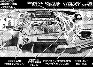
䡵 Engine Compartment 3.7L V6 . . . . . . . . . . . . . . 360
䡵 Engine Compartment 4.7L V-8 . . . . . . . . . . . . . . 361
䡵 Engine Compartment 5.7L HEMI V-8 . . . . . . . . . 362
䡵 Onboard Diagnostic System — OBD II . . . . . . . . 363
▫ Loose Fuel Filler Cap Message . . . . . . . . . . . . 363䡵 Emissions Inspection And Maintenance
Programs
. . . . . . . . . . . . . . . . . . . . . . . . . . . . 364
䡵 Replacement Parts . . . . . . . . . . . . . . . . . . . . . . 365
䡵 Dealer Service . . . . . . . . . . . . . . . . . . . . . . . . . 366䡵 Maintenance Procedures . . . . . . . . . . . . . . . . . . 366
▫ Engine Oil . . . . . . . . . . . . . . . . . . . . . . . . . . 367
▫ Engine Oil Filter . . . . . . . . . . . . . . . . . . . . . . 370
▫ Drive Belts — Check Condition And Tension . . 371
▫ Spark Plugs . . . . . . . . . . . . . . . . . . . . . . . . . 371
▫ Engine Air Cleaner Filter . . . . . . . . . . . . . . . . 372
▫ Engine Fuel Filter . . . . . . . . . . . . . . . . . . . . . 372
▫ Catalytic Converter . . . . . . . . . . . . . . . . . . . . 373
▫ Maintenance Free Battery . . . . . . . . . . . . . . . . 374358 MAINTAINING YOUR VEHICLE
▫ Air Conditioner Maintenance . . . . . . . . . . . . . 375
▫ Power Steering — Fluid Check . . . . . . . . . . . . 377
▫ Front Suspension Ball Joints . . . . . . . . . . . . . . 377
▫ Drive Shaft Constant Velocity Joints . . . . . . . . 378
▫ Body Lubrication . . . . . . . . . . . . . . . . . . . . . 378
▫ Windshield Wiper Blades . . . . . . . . . . . . . . . . 378
▫ Windshield Washers . . . . . . . . . . . . . . . . . . . 379
▫ Exhaust System . . . . . . . . . . . . . . . . . . . . . . 380
▫ Cooling System . . . . . . . . . . . . . . . . . . . . . . . 381
▫ Emission Related Components . . . . . . . . . . . . 386
▫ Brake System . . . . . . . . . . . . . . . . . . . . . . . . 387
▫ Automatic Transmission . . . . . . . . . . . . . . . . 389
▫ Transfer Case . . . . . . . . . . . . . . . . . . . . . . . . 391▫ Axles . . . . . . . . . . . . . . . . . . . . . . . . . . . . . . 392
▫ Selection Of Lubricating Grease . . . . . . . . . . . 392
▫ Appearance Care And Protection FromCorrosion . . . . . . . . . . . . . . . . . . . . . . . . . . . 393
䡵 Fuse Block . . . . . . . . . . . . . . . . . . . . . . . . . . . . 398
▫ Fuses (Interior) . . . . . . . . . . . . . . . . . . . . . . . 398
▫ Fuses (Power Distribution Center) . . . . . . . . . 402
▫ Fuses (Integrated Power Module) . . . . . . . . . . 405
䡵 Vehicle Storage . . . . . . . . . . . . . . . . . . . . . . . . 407
䡵 Replacement Light Bulbs . . . . . . . . . . . . . . . . . 407
䡵 Bulb Replacement . . . . . . . . . . . . . . . . . . . . . . 408
. . . . . . . . . . 408▫ Headlights/Parking/Turn Signal ▫ Rear Side Marker, Tail Lights, Turn Signals And
Backup Lights — Replacement . . . . . . . . . . . . 409
▫ License Lights . . . . . . . . . . . . . . . . . . . . . . . . 413
▫ Center High-Mounted Stoplight . . . . . . . . . . . 414
▫ Fog Lights . . . . . . . . . . . . . . . . . . . . . . . . . . 415
. . . . . . . . . . . . . . . . . . . 417䡵 Fluids And Capacities
MAINTAINING YOUR VEHICLE 359
䡵 Fluids, Lubricants And Genuine Parts . . . . . . . . 418
▫ Engine . . . . . . . . . . . . . . . . . . . . . . . . . . . . . 418
▫ Chassis . . . . . . . . . . . . . . . . . . . . . . . . . . . . 419360 MAINTAINING YOUR VEHICLE
ENGINE COMPARTMENT 3.7L V6
ENGINE COMPARTMENT 4.7L V-8
MAINTAINING YOUR VEHICLE 361
362 MAINTAINING YOUR VEHICLE
ENGINE COMPARTMENT 5.7L HEMI V-8
ONBOARD DIAGNOSTIC SYSTEM — OBD II Your vehicle is equipped with a sophisticated onboard diagnostic system called OBD II. This system monitors the performance of the emissions, engine, and automatic transmission control systems. When these systems are operating properly, your vehicle will provide excellent performance and fuel economy, as well as engine emis- sions well within current government regulations. If any of these systems require service, the OBD II system will turn on the “Malfunction Indicator Light.” It will also store diagnostic codes and other information to assist your service technician in making repairs. Al- though your vehicle will usually be drivable and not need towing, see your dealer for service as soon as possible.
MAINTAINING YOUR VEHICLE 363
CAUTION!
• Prolonged driving with the “Malfunction Indica- tor Light” on could cause further damage to the emission control system. It could also affect fuel economy and driveability. The vehicle must be serviced before any emissions tests can be per- formed. • If the “Malfunction Indicator Light” is flashing while the engine is running, severe catalytic con- verter damage and power loss will soon occur. Immediate service is required.
Loose Fuel Filler Cap Message After fuel is added, the vehicle diagnostic system can determine if the fuel filler cap is loose, improperly installed, or damaged. A loose fuel filler cap message will be displayed in the instrument cluster. Tighten the gas
364 MAINTAINING YOUR VEHICLE
cap until a ⬙clicking⬙ sound is heard. This is an indication that the gas cap is properly tightened. Press the odometer reset button to turn the message off. If the problem persists, the message will appear the next time the vehicle is started. This might indicate a damaged cap. If the problem is detected twice in a row, the system will turn on the Malfunction Indicator Light (MIL). Resolving the problem will turn the MIL light off.
EMISSIONS INSPECTION AND MAINTENANCE PROGRAMS In some localities, it may be a legal requirement to pass an inspection of your vehicle’s emissions control system. Failure to pass could prevent vehicle registration.
For states which have an I/M (Inspection and Maintenance) requirement, this check verifies the following: the MIL (Malfunction Indicator Lamp)
is functioning and is not on when the engine is running, and that the OBD (On Board Diagnostic) system is ready for testing. Normally, the OBD system will be ready. The OBD system may not be ready if your vehicle was recently serviced, if you recently had a dead battery, or a battery replacement. If the OBD system is determined not ready for the I/M test, your vehicle may fail the test. Your vehicle has a simple ignition key actuated test which you can use prior to going to the test station. To check if your vehicle’s OBD system is ready, you must do the following: 1. Insert your ignition key into the ignition switch. 2. Turn the ignition to the ON position, but do not crank or start the engine. If you crank or start the engine, you will have to start this test over.
3. As soon as you turn your key to the ON position, you will see your MIL symbol come on as part of a normal bulb check. 4. Approximately 15 seconds later, one of two things will happen:
a. The MIL light will blink for approximately 5 sec- onds and then remain on until the first engine crank or the key is turned off. This means that your vehicle’s OBD system is not ready and you should not proceed to the I/M station. b. The MIL light will remain fully illuminated until the first engine crank or the key is turned off. This means that your vehicle’s OBD system is ready and you can proceed to the I/M station.
If your OBD system is not ready you should see your dealer or repair facility. If your vehicle was recently serviced or had a battery failure or replacement, you may
MAINTAINING YOUR VEHICLE 365
need to do nothing more than drive your vehicle as you normally would in order for your OBD system to update. A recheck with the above test routine may then indicate that the system is now ready. Regardless of whether your vehicle’s OBD system is ready or not ready, if the MIL symbol is illuminated during normal vehicle operation, you should have your vehicle serviced before going to the I/M station. The I/M station can fail your vehicle because the MIL symbol is on with the engine running.
REPLACEMENT PARTS Use of genuine Mopar威 parts for normal/scheduled maintenance and repairs is highly recommended to in- sure the designed performance. Damage or failures caused by the use of non-Mopar威 parts for maintenance and repairs will not be covered by the manufacturer’s warranty.
366 MAINTAINING YOUR VEHICLE
DEALER SERVICE Your dealer has the qualified service personnel, special tools and equipment to perform all service operations in an expert manner. Service manuals are available which include detailed service information for your vehicle. Refer to these manuals before attempting any procedure yourself. NOTE: systems can result against you.
Intentional tampering with emissions control in civil penalties being assessed
WARNING!
You can be badly injured working on or around a motor vehicle. Do only that service work for which you have the knowledge and the proper equipment. If you have any doubt about your ability to perform a service job, take your vehicle to a competent mechanic.
MAINTENANCE PROCEDURES The pages that follow contain the required maintenance services determined by the engineers who designed your vehicle. Besides the maintenance items for which there are fixed maintenance intervals, there are other items that should operate satisfactorily without periodic maintenance. However, if a malfunction of these items does occur, it
could adversely affect the engine or vehicle performance. These items should be inspected if a malfunction is observed or suspected. Engine Oil
Checking Oil Level To assure proper lubrication of your vehicle’s engine, the engine oil must be maintained at the correct level. The best time to check the engine oil level is about 5 minutes after a fully warmed up engine is shut off or before starting the engine after it has sat overnight. Checking the oil while the vehicle is on level ground will improve the accuracy of the oil level readings. Always maintain the oil level within the SAFE zone on the dipstick. Adding one quart of oil when the reading is at the bottom of the SAFE zone will result in a reading at the top of the safe zone on these engines.
MAINTAINING YOUR VEHICLE 367
CAUTION!
Overfilling or underfilling the crankcase will cause oil aeration or loss of oil pressure. This could dam- age your engine.
368 MAINTAINING YOUR VEHICLE
Change Engine Oil Road conditions and your style of driving affect the interval at which your oil should be changed. Check the following to determine if ANY apply to you: • Day or night temperatures are below 32°F (0°C). • Stop and Go driving. • Extensive engine idling. • Driving in dusty conditions. • Short trips of less than 10 miles (16.2 km). • More than 50% of your driving is at sustained high • Trailer towing, Taxi, Police or delivery service (com- • Off-Road or desert operation.
speeds during hot weather, above 90°F (32°C).
mercial service).
• If equipped for and operating with E-85 (ethanol)
fuel.
If ANY of these apply to you then change your NOTE: engine oil every 3,000 miles (5 000 km) or 3 months, whichever comes first and follow schedule “B” of the ⬙Maintenance Schedules⬙ section of this manual. If none of these apply to you, then change your engine oil at every interval shown on schedule ⬙A⬙ of the ⬙Mainte- nance Schedules⬙ section of this manual. NOTE: Under no circumstances should oil change in- tervals exceed 6,000 miles (10 000 km) or 6 months whichever comes first. 4x4 Models, If Used Primarily For Off-Road Operation Every 50 hours of use.
Dusty Conditions Driving through dust-laden air increases the problems of keeping abrasive materials out of the engine. Under these conditions, special attention should be given to the engine air cleaner and the crankcase inlet air cleaner. The crankcase ventilation system should also be checked periodically. Make sure that these units are always clean. This will tend to reduce to a minimum the amount of abrasive material that may enter the engine. Engine Oil Selection For best performance and maximum protection under all types of operating conditions, the manufacture only recommends engine oils that are API certified and meet the requirements of DaimlerChrysler Material Standard MS-6395.
MAINTAINING YOUR VEHICLE 369
American Petroleum Institute (API) Engine Oil Identification Symbol
This symbol means that the oil has been certified by the American Petroleum Institute (API). The manufacture only recommends API Certified engine oils.
Engine Oil Viscosity (SAE Grade) SAE 5W-20 engine oil is recommended for all operating temperatures. This engine oil improves low tempera- ture starting and vehicle fuel economy. Your engine oil filler cap also shows the recommended engine oil viscosity for your vehicle. For information on engine oil filler cap location, see the Engine Compartment illustration in this section.
370 MAINTAINING YOUR VEHICLE
Lubricants which do not have both, the engine oil certi- fication mark and the correct SAE viscosity grade num- ber should not be used. Synthetic Engine Oils You may use synthetic engine oils provided the recom- mended oil quality requirements are met, and the recom- mended maintenance intervals for oil and filter changes are followed. Materials Added to Engine Oils The manufacture strongly recommends against the addi- tion of any additives (other than leak detection dyes) to the engine oil. Engine oil is an engineered product and it’s performance may be impaired by supplemental ad- ditives.
Disposing of Used Engine Oil And Oil Filters Care should be taken in disposing of used engine oil and oil filters from your vehicle. Used oil and oil filters, indiscriminately discarded, can present a problem to the environment. Contact your dealer, service station, or governmental agency for advice on how and where used oil and oil filters can be safely discarded in your area. Engine Oil Filter The engine oil filter should be replaced at every engine oil change. Engine Oil Filter Selection The manufacturer’s engines have a full-flow type oil filter. Use a filter of this type for replacement. The quality of replacement filters varies considerably. Only high quality filters should be used to assure most efficient service. Mopar威 Engine Oil Filters are a high quality oil filter and are recommended.
Drive Belts — Check Condition and Tension Belt tension is controlled by means of an automatic tensioner. No belt tension adjustments are required. However, belt and belt tensioner condition should be inspected at the specified intervals, and replaced if re- quired. See your authorized dealer for service. At the mileage indicated in the maintenance schedule, all belts and tensioner should be checked for condition. Improper belt tension can cause belt slippage and failure. Belts should be inspected for evidence of cuts, cracks, glazing, or frayed cords and replaced if there is indication of damage which could result in belt failure. Low generator belt tension can cause battery failure. Also check belt routing to make sure there is no interference between the belts and other engine components.
MAINTAINING YOUR VEHICLE 371
Spark Plugs Spark plugs must fire properly to assure proper engine performance and emission control. The plugs installed in your vehicle should operate satisfactorily in normal service for the mileage indicated in the Maintenance Chart. New plugs should be installed at this mileage. The entire set should be replaced if there is any malfunction due to a faulty spark plug. Check the Vehicle Emissions Control Information label for the proper type of spark plug for your vehicle.
CAUTION!
When replacing plugs, do not overtighten. You could damage them and cause them to leak.
372 MAINTAINING YOUR VEHICLE
Engine Air Cleaner Filter Under normal driving conditions, replace the air filter at the intervals shown on Schedule “A”. If, however, you drive the vehicle frequently under dusty or severe con- ditions, the filter element should be inspected periodi- cally and replaced if necessary at the intervals shown on Schedule “B”.
WARNING!
The air cleaner can provide a measure of protection in the case of engine backfire. Do not remove the air cleaner unless such removal is necessary for repair or maintenance. Make sure that no one is near the engine compartment before starting the vehicle with the air cleaner removed. Failure to do so can result in serious personal injury.
Engine Fuel Filter A plugged fuel filter can cause stalling, limit the speed at which a vehicle can be driven or cause hard starting. Should an excessive amount of dirt accumulate in the fuel tank, frequent filter replacement may be necessary.
Catalytic Converter The catalytic converter requires the use of unleaded fuel only. Leaded gasoline will destroy the effectiveness of the catalyst as an emission control device. Under normal operating conditions, the catalytic con- verter will not require maintenance. However, it is im- portant to keep the engine properly tuned to assure proper catalyst operation and prevent possible catalyst damage.
MAINTAINING YOUR VEHICLE 373
CAUTION!
Damage to the catalytic converter can result if your vehicle is not kept in proper operating condition. In the event of engine malfunction, particularly involv- ing engine misfire or other apparent loss of perfor- mance, have your vehicle serviced promptly. Contin- ued operation of your vehicle with a severe malfunction could cause the converter to overheat, resulting in possible damage to the converter and the vehicle.
NOTE: systems can result against you.
Intentional tampering with emissions control in civil penalties being assessed
374 MAINTAINING YOUR VEHICLE
WARNING!
A hot exhaust system can start a fire if you park over materials that can burn. Such materials might be grass or leaves coming into contact with your ex- haust system. Do not park or operate your vehicle in areas where your exhaust system can contact any- thing that can burn.
In unusual situations involving grossly malfunctioning engine operation, a scorching odor may indicate severe and abnormal catalyst overheating. If this occurs, the vehicle should be stopped, the engine shut off and the vehicle allowed to cool. Thereafter, service, including a tune-up to manufacturer’s specifications, should be ob- tained immediately.
To minimize the possibility of catalyst damage: • Do not shut off the engine or interrupt the ignition when the transmission is in gear and the vehicle is in motion. • Do not try to start engine by pushing or towing the • Do not idle the engine with any spark plug wires disconnected or removed, such as when diagnostic testing, or for prolonged periods during very rough idling or malfunctioning operating conditions.
vehicle.
Maintenance Free Battery The top of the maintenance free battery is permanently sealed. You will never have to add water, nor is periodic maintenance required.
WARNING!
• Battery fluid is a corrosive acid solution and can burn or even blind you. Don’t allow battery fluid to contact your eyes, skin or clothing. Don’t lean over a battery when attaching clamps. If acid splashes in eyes or on skin, flush the area imme- diately with large amounts of water. • Battery gas is flammable and explosive. Keep flame or sparks away from the battery. Don’t use a booster battery or any other booster source with an output greater than 12 volts. Don’t allow cable clamps to touch each other. • Battery posts, terminals and related accessories contain lead and lead compounds. Wash hands after handling.
MAINTAINING YOUR VEHICLE 375
CAUTION!
• It is essential when replacing the cables on the battery that the positive cable is attached to the positive post and the negative cable is attached to the negative post. Battery posts are marked (+) positive and negative (-) and identified on the battery case. • If a “fast charger” is used while battery is in vehicle, disconnect both vehicle battery cables before connecting the charger to battery. Do not use a “fast charger” to provide starting voltage.
Air Conditioner Maintenance For best possible performance, your air conditioner should be checked and serviced by an Authorized Dealer at the start of each warm season. This service should
376 MAINTAINING YOUR VEHICLE
include cleaning of the condenser fins and a performance test. Drive belt tension should also be checked at this time.
WARNING!
• Use only refrigerants and compressor lubricants approved by the manufacturer for your air condi- tioning system. Some unapproved refrigerants are flammable and can explode, injuring you. Other unapproved refrigerants or lubricants can cause the system to fail, requiring costly repairs. Refer to Section 3 of the Warranty Information book for further warranty information. • The air conditioning system contains refrigerant under high pressure. To avoid risk of personal injury or damage to the system, adding refrigerant or any repair requiring lines to be disconnected should be done by an experienced repairman.
Refrigerant Recovery and Recycling R-134a Air Conditioning Refrigerant is a hydrofluorocar- bon (HFC) that is endorsed by the Environmental Pro- tection Agency and is an ozone-saving product. How- ever, the manufacturer recommends that air conditioning service be performed by dealers or other service facilities using recovery and recycling equipment. Power Steering — Fluid Check Checking the power steering fluid level at a defined service interval is not required. The fluid should only be checked if a leak is suspected, abnormal noises are apparent, and/or the system is not functioning as antici- pated. Coordinate inspection efforts through a certified DaimlerChrysler Dealership.⬙
MAINTAINING YOUR VEHICLE 377
WARNING!
Fluid level should be checked on a level surface and with the engine off to prevent injury from moving parts and to insure accurate fluid level reading. Do not overfill. Use only manufacturers recommended power steering fluid.
If necessary, add fluid to restore to the proper indicated level. With a clean cloth, wipe any spilled fluid from all surfaces. Refer to Fluids, Lubricants, and Genuine Parts for correct fluid type. Front Suspension Ball Joints The ball joints and seals should be inspected whenever the vehicle is serviced for other reasons. Damaged seals should be replaced to prevent leakage or contamination of the grease.
378 MAINTAINING YOUR VEHICLE
Drive Shaft Constant Velocity Joints All four wheel drive models are equipped with four constant velocity joints. Periodic lubrication of these joints is not required. However, the joint boot should be inspected for external leakage or damage periodically. If external leakage or damage is evident, the joint boot and grease should be replaced immediately. Continued op- eration could result in failure of the joint due to water and dirt contamination of the grease. This would require complete replacement of the joint assembly. Refer to the Service Manual for the detailed replacement procedure. Body Lubrication Locks and all body pivot points, including such items as seat tracks, doors,liftgate and hood hinges, should be lubricated periodically to assure quiet, easy operation and to protect against rust and wear. Prior to the appli- cation of any lubricant, the parts concerned should be wiped clean to remove dust and grit; after lubricating excess oil and grease should be removed. Particular
attention should also be given to hood latching compo- nents to insure proper function. When performing other underhood services, the hood latch, release mechanism and safety catch should be cleaned and lubricated. The external lock cylinders should be lubricated twice a year, preferably in the fall and spring. Apply a small amount of a high quality lubricant such as Mopar威 Lock Cylinder Lubricant directly into the lock cylinder. Windshield Wiper Blades The rubber edges of the wiper blades and the windshield should be cleaned periodically with a sponge or soft cloth and a mild nonabrasive cleaner. This will remove accu- mulations of salt or road film. Operation of the wipers on dry glass for long periods may cause deterioration of the wiper blades. Always use washer fluid when using the wipers to remove salt or dirt from a dry windshield.
Avoid using the wiper blades to remove frost or ice from the windshield. Keep the blade rubber out of contact with petroleum products such as engine oil, gasoline, etc. Windshield Washers The fluid reservoir should be checked for fluid level at regular intervals. Always fill the reservoir with wind- shield washer fluid (not radiator antifreeze). To prevent freeze-up of your windshield washer system in cold weather, select a solution or mixture that meets or exceeds the temperature range of your climate. This rating information can be found on most washer fluid containers.
MAINTAINING YOUR VEHICLE 379
WARNING!
Commercially available windshield washer solvents are flammable. They could ignite and burn you. Care must be exercised when filling or working around the washer solution.
After the engine has warmed, operate the defroster for a few minutes to reduce the possibility of smearing or freezing the fluid on the cold windshield. Mopar威 All Weather Windshield Washer Solution used with water as directed on the container, aids cleaning action, reduces freezing point to avoid line clogging, and is not harmful to paint or trim.
380 MAINTAINING YOUR VEHICLE
Exhaust System The best protection against carbon monoxide entry into the vehicle body is a properly maintained engine exhaust system. Whenever a change is noticed in the sound of the exhaust system, when exhaust fumes can be detected inside the vehicle, or when the underside or rear of the vehicle is damaged, have a competent mechanic inspect the com- plete exhaust system and adjacent body areas for broken, damaged, deteriorated, or mispositioned parts. Open seams or loose connections could permit exhaust fumes to seep into the passenger compartment. In addition, inspect the exhaust system each time the vehicle is raised for lubrication or oil change. Replace as required.
WARNING!
Exhaust gases can injure or kill. They contain carbon monoxide (CO) which is colorless and odorless. Breathing it can make you unconscious and can eventually poison you. To avoid breathing CO, fol- low the preceding safety tips.
Cooling System
WARNING!
You or others can be badly burned by hot coolant or steam from your radiator. If you see or hear steam coming from under the hood, don’t open the hood until the radiator has had time to cool. Never try to open a cooling system pressure cap when the radia- tor is hot.
Engine Coolant Checks Check the engine coolant (antifreeze) protection every 12
months (before the onset of freezing weather, where applicable). If coolant is dirty or rusty in appearance, the system should be drained, flushed and refilled with fresh coolant. Check the front of the A/C condenser for anyMAINTAINING YOUR VEHICLE 381
accumulation of bugs, leaves, etc. If dirty, clean by gently spraying water from a garden hose vertically down the face of the condenser. Check the coolant recovery bottle tubing for brittle rub- ber, cracking, tears, cuts and tightness of the connection at the bottle and radiator. Inspect the entire system for leaks. With the engine at normal operating temperature (but not running), check the cooling system pressure cap for proper vacuum sealing by draining a small amount of coolant from the radiator drain cock. If the cap is sealing properly, the engine coolant (antifreeze) will begin to drain from the coolant recovery bottle. DO NOT RE- MOVE THE COOLANT PRESSURE CAP WHEN THE COOLING SYSTEM IS HOT. Cooling System — Drain, Flush and Refill At the intervals shown on the Maintenance Schedules, the system should be drained, flushed and refilled.
382 MAINTAINING YOUR VEHICLE
If the solution is dirty or contains a considerable amount of sediment, clean and flush with a reliable cooling system cleaner. Follow with a thorough rinsing to remove all deposits and chemicals. Properly dispose of old antifreeze solution. Selection Of Coolant Use only the manufacturers recommended coolant, refer to Fluids, Lubricants and Genuine Parts for correct coolant type.
CAUTION!
Mixing of coolants other than specified HOAT en- gine coolants, may result in engine damage and may decrease corrosion protection. If a non-HOAT cool- ant is introduced into the cooling system in an emergency, it should be replaced with the specified coolant as soon as possible. Do not use plain water alone or alcohol base engine coolant (antifreeze) products. Do not use additional rust inhibitors or antirust products, as they may not be compatible with the radiator engine coolant and may plug the radiator. This vehicle has not been designed for use with Propylene Glycol based coolants. Use of Propylene Glycol based coolants is not recommended.
Adding Coolant Your vehicle has been built with an improved engine coolant that allows extended maintenance intervals. This coolant can be used up to 5 Years or 100,000 miles before replacement. To prevent reducing this extended mainte- nance period, it is important that you use the same coolant throughout the life of your vehicle. Please review these recommendations for using Hybrid Organic Addi- tive Technology (HOAT) coolant. When adding coolant, a minimum solution of 50% rec- ommended Mopar Antifreeze/ Coolant 5 Year/100,000
Mile Formula HOAT (Hybrid Organic Additive Technol- ogy), or equivalent, in water should be used. Use higher concentrations (not to exceed 70%) if temperatures below ⫺34°F (⫺37°C ) are anticipated. Use only high purity water such as distilled or deionized water when mixing the water/engine coolant solution.MAINTAINING YOUR VEHICLE 383
The use of lower quality water will reduce the amount of corrosion protection in the engine cooling system. Please note that it is the owner’s responsibility to main- tain the proper level of protection against freezing ac- cording to the temperatures occurring in the area where the vehicle is operated. NOTE: Mixing coolant types will decrease the life of the engine coolant and will require more frequent coolant changes. Cooling System Pressure Cap The cap must be fully tightened to prevent loss of coolant, and to insure that coolant will return to the radiator from the coolant recovery bottle. The cap should be inspected and cleaned if there is any accumulation of foreign material on the sealing surfaces.
384 MAINTAINING YOUR VEHICLE
WARNING!
• The warning words “DO NOT OPEN HOT” on the cooling system pressure cap are a safety pre- caution. Never add coolant when the engine is overheated. Do not loosen or remove the cap to cool an overheated engine. Heat causes pressure to build up in the cooling system. To prevent scalding or injury, do not remove the pressure cap while the system is hot or under pressure. • Do not use a pressure cap other than the one specified for your vehicle. Personal injury or engine damage may result.
Disposal of Used Engine Coolant Used ethylene glycol based engine coolant is a regulated substance requiring proper disposal. Check with your local authorities to determine the disposal rules for your community. To prevent ingestion by animals or children
do not store ethylene glycol based engine coolant in open containers or allow it to remain in puddles on the ground. If ingested by a child, contact a physician immediately. Clean up any ground spills immediately. Coolant Level The coolant bottle provides a quick visual method for determining that the coolant level is adequate. With the engine cold, the level of the coolant in the coolant recovery bottle should be between the ranges indicated on the bottle. The radiator normally remains completely full, so there is no need to remove the radiator cap unless checking for coolant freeze point or replacing coolant. Advise your service attendant of this. As long as the engine operating temperature is satisfactory, the coolant bottle need only be checked once a month.
When additional coolant is needed to maintain the