- 2011 Dodge Durango Owners Manuals
- Dodge Durango Owners Manuals
- 2008 Dodge Durango Owners Manuals
- Dodge Durango Owners Manuals
- 2009 Dodge Durango Owners Manuals
- Dodge Durango Owners Manuals
- 2007 Dodge Durango Owners Manuals
- Dodge Durango Owners Manuals
- 2004 Dodge Durango Owners Manuals
- Dodge Durango Owners Manuals
- 2013 Dodge Durango Owners Manuals
- Dodge Durango Owners Manuals
- 2005 Dodge Durango Owners Manuals
- Dodge Durango Owners Manuals
- 2006 Dodge Durango Owners Manuals
- Dodge Durango Owners Manuals
- 2012 Dodge Durango Owners Manuals
- Dodge Durango Owners Manuals
- Download PDF Manual
-
NOTE: The 4x4 system will not allow shifts between AWD/ 4LOCK if the rear wheels are spinning (no traction). In this situation a position indicator light will flash and the original position indicator light will remain ON. At this time, reduce speed and stop spinning the
STARTING AND OPERATING 233
wheels to complete the shift. There may be a delay up to 13 seconds for the shift to complete after the wheels have stopped spinning. NOTE: Delayed shifting out of the 4LOCK position may be experienced due to uneven tire wear, low tire pressure, or excessive loading. NOTE: When shifting into or out of 4LO some gear noise may be heard. This noise is normal and is not detrimental to the vehicle or occupants. Shifting can be performed with the vehicle rolling 2 to 3
mph (3 to 5 km/h) or completely stopped. USE EITHER OF THE FOLLOWING PROCEDURES: Preferred Procedure 1. With the engine RUNNING, slow vehicle to 2 to 3
mph (3 to 5 km/h). 2. Shift the transmission into NEUTRAL.If any of the requirements to select a new NOTE: transfer case position have not been met, the transfer case will not shift. The indicator light will flash and the current transfer case position will be maintained. To retry the selection, turn the control knob back to the current position, wait five (5) seconds, and retry the shift.
PARKING BRAKE The foot operated parking brake is positioned below the lower left corner of the instrument panel. To release the parking brake, pull the parking brake release handle.
234 STARTING AND OPERATING
3. While still rolling, rotate the transfer case control switch to the desired position. 4. After the position indicator light has stopped flashing, shift the transmission back into gear. Alternate Procedure 1. Bring the vehicle to complete stop. 2. With the key ON and the engine either OFF or RUNNING, shift the transmission into NEUTRAL. 3. Rotate the transfer case control switch to the desired position. 4. After the position indicator light has stopped flashing, shift the transmission back into gear. NOTE: The ignition key must be ON for a shift to take place and for the position indicator lights to be operable. If the key is not ON then the shift will not take place and no position indicator lights will be on or flashing.
STARTING AND OPERATING 235
NOTE: The instrument cluster brake warning light indicates only that the parking brake is applied. You must be sure the parking brake is fully applied before leaving the vehicle. When parking on a hill, turn the front wheels toward the curb on a downhill grade and away from the curb on an uphill grade. The parking brake should be applied whenever the driver is not in the vehicle.
Be sure the parking brake is firmly set when parked and the gear-shift lever is in PARK position. When parking on a hill you should apply the Parking Brake before placing the gear shift lever in PARK; otherwise the load on the transmission locking mechanism may make it difficult to move the selector out of PARK.
236 STARTING AND OPERATING
WARNING!
• Always fully apply the parking brake when leav- ing your vehicle, or vehicle may roll and cause damage or injury. Also be certain to leave an automatic transmission in Park. Failure to do so may cause the vehicle to roll and cause damage or injury. • Be sure the parking brake is fully disengaged before driving, failure to do so can lead to brake failure and an accident. • Leaving children in a vehicle unattended is dan- gerous for a number of reasons. A child or others could be injured. Children should be warned not to touch the parking brake or the gear selector lever. Don’t leave the key in the ignition. A child could operate power windows, other controls, or move the vehicle.
BRAKE SYSTEM In the event power assist is lost for any reason, (for example, repeated brake applications with the engine off), the brakes will still function. The effort required to brake the vehicle will be significantly increased over that required with the power system operating. If either the front or rear hydraulic systems lose normal capability, the remaining system will still function with some loss of braking effectiveness. This will be evident by increased pedal travel during application, greater pedal force required to slow or stop, and activation of the Brake Warning Lamp and the ABS Lamp during brake use. Four-Wheel Anti-Lock Brake System (ABS) This Anti-Lock Brake System is designed to aid the driver in maintaining vehicle control under adverse braking conditions. The system operates with a separate com- puter to modulate hydraulic pressure to prevent wheel lockup and help avoid skidding on slippery surfaces.
The system’s pump motor runs during an ABS stop to provide regulated hydraulic pressure. The pump motor makes a low humming noise during operation, which is normal. The Anti-Lock Brake system includes an amber (ABS) warning light. When the light is illuminated, the Anti- Lock Brake system is not functioning. The system reverts to standard non-anti-lock brakes. Turning the ignition Off and On again may reset the Anti-Lock Brake system if the fault detected was only momentary.
STARTING AND OPERATING 237
WARNING!
Anti-Lock Brake Systems contain sophisticated elec- tronic equipment. It may be susceptible to interfer- ence caused by improperly installed or high output radio transmitting equipment. This interference can cause possible loss of anti-lock braking capability. Installation of such equipment should be done by qualified professionals.
WARNING!
Pumping of the Anti-Lock Brakes will diminish their effectiveness and may lead to an accident. Pumping makes the stopping distance longer. Just press firmly on your brake pedal when you need to slow down or stop.
238 STARTING AND OPERATING
WARNING!
• Anti-lock system (ABS) cannot prevent the natu- ral laws of physics from acting on the vehicle, nor can it increase braking or steering efficiency be- yond that afforded by the condition of the vehicle brakes and tires or the traction afforded.
• The ABS cannot prevent accidents,
including those resulting from excessive speed in turns, following another vehicle too closely, or hydro- planing. Only a safe, attentive, and skillful driver can prevent accidents. • The capabilities of an ABS equipped vehicle must never be exploited in a reckless or dangerous manner which could jeopardize the user’s safety or the safety of others.
When you are in a severe braking condition involving use of the Anti-lock Brake system, you will experience some pedal drop as the vehicle comes to a stop. This is the result of the system reverting to the base brake system. Engagement of the Anti-lock Brake System may be accompanied by a pulsing sensation. You may also hear a clicking noise. These occurrences are normal, and indi- cate that the system is functioning properly.
POWER STEERING Your power steering system will provide mechanical steering capability if power assist is lost. If for any reason the hydraulic pressure is interrupted, it will still be possible to steer your vehicle. Under these conditions you will experience an increase in steering effort and a noticeable amount of “free play” in the steering wheel.
ROCKING THE VEHICLE If vehicle becomes stuck in snow, sand, or mud, it can often be moved by a rocking motion. Move the gear selector rhythmically between FIRST and REVERSE, while applying slight pressure to the accelerator. The least amount of accelerator pedal pressure to main- tain the rocking motion without spinning the wheels or racing the engine is most effective. Allow the engine to idle with the transmission selector in NEUTRAL for at least one minute after every five rocking-motion cycles. This will minimize overheating and reduce the risk of transmission failure during prolonged efforts to free a stuck vehicle.
STARTING AND OPERATING 239
TIRE SAFETY INFORMATION
Tire Markings
NOTE: • P(Passenger)-Metric tire sizing is based on U.S. design standards. P-Metric tires have the letter “P” molded into the sidewall preceding the size designation. Ex- ample: P215/65R15 95H.
240 STARTING AND OPERATING
• European Metric tire sizing is based on European design standards. Tires designed to this standard have the tire size molded into the sidewall beginning with the section width. The letter ⬙P⬙ is absent from this tire size designation. Example: 215/65R15 96H • LT(Light Truck)-Metric tire sizing is based on U.S. design standards. The size designation for LT-Metric tires is the same as for P-Metric tires except for the letters “LT” that are molded into the sidewall preced- ing the size designation. Example: LT235/85R16.
• Temporary Spare tires are high pressure compact spares designed for temporary emergency use only. Tires designed to this standard have the letter “T” molded into the sidewall preceding the size designa- tion. Example: T145/80D18 103M. • High Flotation tire sizing is based on U.S. design standards and begins with the tire diameter molded into the sidewall. Example: 31x10.5 R15 LT.
Tire Sizing Chart
Size Designation:
EXAMPLE:
P = Passenger car tire size based on U.S. design standards ⴖ....blank....ⴖ = Passenger car tire based on European design standards LT = Light Truck tire based on U.S. design standards T = Temporary Spare tire 31 = Overall Diameter in Inches (in) 215 = Section Width in Milimeters (mm) 65 = Aspect Ratio in Percent (%)
—Ratio of section height to section width of tire.
10.5 = Section Width in Inches (in) R = Construction Code
—⬙R⬙ means Radial Construction. —⬙D⬙ means Diagonal or Bias Construction.
15 = Rim Diameter in Inches (in)
STARTING AND OPERATING 241
242 STARTING AND OPERATING
Service Description:
EXAMPLE:
95 = Load Index
—A numerical code associated with the maximum load a tire can carry.
H = Speed Symbol
—A symbol indicating the range of speeds at which a tire can carry a load corresponding to its load index under certain operating conditions. —The maximum speed corresponding to the Speed Symbol should only be achieved un- der specified operating conditions. (ie. tire pressure, vehicle loading, road conditions and posted speed limits).
Load Identification:
ⴖ....blank....ⴖ = Absence of any text on sidewall of the tire indicates a Standard Load (SL) Tire Extra Load (XL) = Extra Load (or Reinforced) Tire Light Load = Light Load Tire C,D,E = Load range associated with the maximum load a tire can carry at a specified pressure
Maximum Load — Maximum Load indicates the maximum load this tire is designed to carry. Maximum Pressure — Maximum Pressure indicates the maximum permissible cold tire inflation pressure for this tire.
Tire Identification Number (TIN) The TIN may be found on one or both sides of the tire however the date code may only be on one side. Tires with white sidewalls will have the full TIN including date code located on the white sidewall side of the tire.
STARTING AND OPERATING 243
Look for the TIN on the outboard side of black sidewall tires as mounted on the vehicle. If the TIN is not found on the outboard side then you will find it on the inboard side of the tire.
EXAMPLE:
DOT MA L9 ABCD 0301
DOT = Department of Transportation
—This symbol certifies that the tire is in compliance with the U.S. Department of Transportation tire safety standards, and is approved for highway use.
MA = Code representing the tire manufacturing location.(2 digits) L9 = Code representing the tire size.(2 digits) ABCD = Code used by tire manufacturer.(1 to 4 digits) 03 = Number representing the week in which the tire was manufactured.(2 digits)
—03 means the 3rd week.
244 STARTING AND OPERATING
01 = Number representing the year in which the tire was manufactured.(2 digits)
EXAMPLE:
—01 means the year 2001. —Prior to July 2000, tire manufacturers were only required to have 1 number to represent the year in which the tire was manufactured. Example: 031 could represent the 3rd week of 1981 or 1991.
Tire Loading and Tire Pressure
Tire Placard Location NOTE: The proper cold tire inflation pressure for pas- senger cars is listed on either the face of the driver’s door or the driver’s side “B” pillar. For vehicles other than passenger cars, the cold tire inflation pressures are listed on either the shutface of the driver’s door, the “B” pillar, the Certification Label or in the Tire Inflation Pressures brochure in the glove compartment.
Tire Placard Location
Tire and Loading Information Placard
Tire and Loading Information
This placard tells you important information about the: 1) number of people that can be carried in the vehicle 2) the total weight your vehicle can carry 3) the tire size designed for your vehicle
STARTING AND OPERATING 245
4) the cold tire inflation pressures for the front, rear and spare tires. Loading The vehicle maximum load on the tire must not exceed the load carrying capacity of the tire on your vehicle. You will not exceed the tire’s load carrying capacity if you adhere to the loading conditions, tire size and cold tire inflation pressures specified on the Tire and Loading Information placard and the Vehicle Loading section of this manual. NOTE: Under a maximum loaded vehicle condition, gross axle weight ratings (GAWR’s) for the front and rear axles must not be exceeded. For further information on GAWR’s, vehicle loading and trailer towing, see the Vehicle Loading section of this manual. To determine the maximum loading conditions of your vehicle, locate the statement “The combined weight of occupants and cargo should never exceed XXX kg or XXX
246 STARTING AND OPERATING
lbs.” on the Tire and Loading Information placard. The combined weight of occupants, cargo/luggage and trailer tongue weight (if applicable) should never exceed the weight referenced here. Steps for Determining Correct Load Limit 1. Locate the statement “The combined weight of occu- pants and cargo should never exceed XXX pounds” on your vehicle’s placard. 2. Determine the combined weight of the driver and passengers that will be riding in your vehicle. 3. Subtract the combined weight of the driver and pas- sengers from XXX kilograms or XXX pounds. 4. The resulting figure equals the available amount of cargo and luggage load capacity. For example, if “XXX” amount equals 1400 lbs. and there will be five 150 lb. passengers in your vehicle, the amount of available cargo and luggage load capacity is 650 lb. (since 5 x 150 = 750, and 1400 – 750 = 650 lb.)
5. Determine the combined weight of luggage and cargo being loaded on the vehicle. That weight may not safely exceed the available cargo and luggage load capacity calculated in step 4. 6. If your vehicle will be towing a trailer, load from your trailer will be transferred to your vehicle. Consult this manual to determine how this reduces the available cargo and luggage load capacity of your vehicle. NOTE: The following table shows examples on how to calculate total load, cargo/luggage and towing capacities of your vehicle with varying seating configurations and number and size of occupants. This table is for illustra- tion purposes only and may not be accurate for the seating and load carry capacity of your vehicle. NOTE: For the following example the combined weight of occupants and cargo should never exceed 865 lbs. (392
Kg).STARTING AND OPERATING 247
248 STARTING AND OPERATING
WARNING!
1. Safety—
Overloading of your tires is dangerous. Overloading can cause tire failure, affect vehicle handling, and increase your stopping distance. Use tires of the recommended load capacity for your vehicle. Never overload them.
TIRES—GENERAL INFORMATION
Tire Pressure Proper tire inflation pressure is essential to the safe and satisfactory operation of your vehicle. Three primary areas are affected by improper tire pressure:
WARNING!
Improperly inflated tires are dangerous and can cause accidents. • Under inflation increases tire flexing and can result in tire failure. • Over inflation reduces a tire’s ability to cushion shock. Objects on the road and chuck holes can cause damage that results in tire failure. • Unequal tire pressures can cause steering prob- lems. You could lose control of your vehicle. • Over inflated or under inflated tires can affect vehicle handling and can fail suddenly, resulting in loss of vehicle control. • Unequal tire pressures from one side of the vehicle to the other can cause the vehicle to drift to the right or left. Always drive with each tire inflated to the recom- mended cold tire inflation pressure.
2. Economy— Improper inflation pressures can cause uneven wear patterns to develop across the tire tread. These abnormal wear patterns will reduce tread life resulting in a need for earlier tire replacement. Underinflation also increases tire rolling resistance and results in higher fuel consumption. 3. Ride Comfort and Vehicle Stability— Proper tire inflation contributes to a comfortable ride. Overinflation produces a jarring and uncomfortable ride. Tire Inflation Pressures The proper cold tire inflation pressure for passenger cars is listed on either the face of the driver’s door or the driver’s side “B” pillar. For vehicles other than passenger cars, the cold tire inflation pressures are listed on either the “B” pillar, the Certification Label or in the Tire Inflation Pressures brochure in the glove compartment. Some vehicles may have Supplemental Tire Pressure Information for vehicle loads that are less than the
STARTING AND OPERATING 249
maximum loaded vehicle condition. These pressure con- ditions will be found in the “Supplemental Tire Pressure Information” section of this manual.
Tire Placard Location
The pressure should be checked and adjusted as well as inspecting for signs of tire wear or visible damage at least once a month. Use a good quality pocket-type gauge to
250 STARTING AND OPERATING
check tire pressure. Do not make a visual judgement when determining proper inflation. Radial tires may look properly inflated even when they are under inflated.
CAUTION!
After inspecting or adjusting the tire pressure al- ways reinstall the valve stem cap–if equipped. This will prevent moisture and dirt from entering the valve stem, which could damage the valve stem.
Inflation pressures specified on the placard are always “cold tire inflation pressure”. Cold tire inflation pressure is defined as the tire pressure after the vehicle has not been driven for at least 3 hours, or driven less than 1mile (1 km) after a 3 hour period. The cold tire inflation pressure must not exceed the maximum inflation pres- sure molded into the tire side wall.
Check tire pressures more often if subject to a wide range of outdoor temperatures, as tire pressures vary with temperature changes. Tire pressures change by approximately 1 psi (7 kPa) per 12° F (7° C) of air temperature change. Keep this in mind when checking tire pressure inside a garage especially in the winter. Example: If garage temperature = 68° F (20° C) and the outside temperature = 32° F (0° C) then the cold tire inflation pressure should be increased by 3 psi (21 kPa), which equals 1 psi (7 kPa) for every 12° F (7° C) for this outside temperature condition. Tire pressure may increase from 2 to 6 psi (13 to 40 kPa) during operation. DO NOT reduce this normal pressure build up or your tire pressure will be too low.
Tire Pressures for High Speed Operation The manufacturer advocates driving at safe speeds within posted speed limits. Where speed limits or condi- tions are such that the vehicle can be driven at high speeds, maintaining correct tire inflation pressure is very important. Increased tire pressure and reduced vehicle loading may be required for high speed vehicle opera- tion. Refer to original equipment or an authorized tire dealer for recommended safe operating speeds, loading and cold tire inflation pressures.
STARTING AND OPERATING 251
WARNING!
High speed driving with your vehicle under maxi- mum load is dangerous. The added strain on your tires could cause them to fail. You could have a serious accident. Don’t drive a vehicle loaded to the maximum capacity at continuous speeds above 75
mph (120 km/h).252 STARTING AND OPERATING
Radial-Ply Tires
WARNING!
Combining radial ply tires with other types of tires on your vehicle will cause your vehicle to handle poorly. The instability could cause an accident. Al- ways use radial ply tires in sets of four (or 6, in case of trucks with dual rear wheels). Never combine them with other types of tires.
Cuts and punctures in radial tires are repairable only in the tread area because of sidewall flexing. Consult your authorized tire dealer for radial tire repairs.
Compact Spare Tire — If Equipped The compact spare is for temporary emergency use with radial tires. It is engineered to be used on your style vehicle only. Since this tire has limited tread life, the original tire should be repaired (or replaced) and rein- stalled at the first opportunity.
WARNING!
Temporary use spare tires are for emergency use only. With these tires, do not drive more than 50 mph (80 km/h). Temporary-use spare tires have limited tread life. When two or more tread wear indicators appear in adjacent grooves, the temporary use spare tire needs to be replaced. Be sure to follow the warnings which apply to your spare. Failure to do so could result in spare tire failure and loss of vehicle control.
Do not install a wheel cover or attempt to mount a conventional tire on the compact spare wheel, since the wheel is designed specifically for the compact spare. Do not install more than one compact spare tire/wheel on the vehicle at any given time.
CAUTION!
Because of the reduced ground clearance, do not take your vehicle through an automatic car wash with the compact spare installed. Damage to the vehicle may result.
STARTING AND OPERATING 253
Limited Use Spare — If Equipped The limited use spare tire is for temporary emergency use on your vehicle. This tire is identified by a limited use spare tire warning label located on the limited use spare tire and wheel assembly. This tire may look like the original equipped tire on the front or rear axle of your vehicle, but it is not. Installation of this limited use spare tire affects vehicle handling. Since it is not the same tire, replace (or repair) the original tire and reinstall on vehicle at the first opportunity.
254 STARTING AND OPERATING
WARNING!
WARNING!
The limited use spare tires are for emergency use only. Installation of this limited use spare tire affects vehicle handling. With this tire, do not drive more than 60 mph (100 km/h). Keep inflated to the cold tire inflation pressure listed on either your tire placard or limited use spare tire and wheel assembly. Replace (or repair) the original tire at the first opportunity and reinstall it on your vehicle. Failure to do so could result in loss of vehicle control.
Tire Spinning When stuck in mud, sand, snow, or ice conditions, do not spin your vehicle’s wheels above 35 mph (55 km/h). See the paragraph on Freeing A Stuck Vehicle in Section 6 of this manual.
Fast spinning tires can be dangerous. Forces gener- ated by excessive wheel speeds may cause tire dam- age or failure. A tire could explode and injure someone. Do not spin your vehicle’s wheels faster than 35 mph (55 km/h) when you are stuck. And don’t let anyone near a spinning wheel, no matter what the speed.
Tread Wear Indicators Tread wear indicators are in the original equipment tires to help you in determining when your tires should be replaced.
STARTING AND OPERATING 255
Replacement Tires The tires on your new vehicle provide a balance of many characteristics. They should be inspected regularly for wear and correct cold tire inflation pressure. The manu- facturer strongly recommends that you use tires equiva- lent to the originals in size, quality and performance when replacement is needed (see the paragraph on tread wear indicators). Refer to the Tire and Loading Informa- tion placard for the size designation of your tire. The service description and load identification will be found on the original equipment tire. Failure to use equivalent replacement tires may adversely affect the safety, han- dling, and ride of your vehicle. We recommend that you contact your original equipment or an authorized tire dealer with any questions you may have on tire specifi- cations or capability.
These indicators are molded into the bottom of the tread grooves and will appear as bands when the tread depth becomes 1/16 inch (2 mm). When the indicators appear in 2 or more adjacent grooves, the tire should be replaced. Many states have laws requiring tire replacement at this point.
256 STARTING AND OPERATING
WARNING!
• Do not use a tire, wheel size or rating other than that specified for your vehicle. Some combinations of unapproved tires and wheels may change sus- pension dimensions and performance characteris- tics, resulting in changes to steering, handling, and braking of your vehicle. This can cause unpredict- able handling and stress to steering and suspen- sion components. You could lose control and have an accident resulting in serious injury or death. Use only the tire and wheel sizes with load ratings approved for your vehicle. • Never use a tire with a smaller load index or capacity, other than what was originally equipped on your vehicle. Using a tire with a smaller load index could result in tire overloading and failure. You could lose control and have an accident. • Failure to equip your vehicle with tires having adequate speed capability can result in sudden tire failure and loss of vehicle control.
CAUTION!
Replacing original tires with tires of a different size may result in false speedometer and odometer read- ings.
Alignment And Balance Poor suspension alignment may result in: • Fast tire wear. • Uneven tire wear, such as feathering and one-sided • Vehicle pull to right or left. Tires may also cause the vehicle to pull to the left or right. Alignment will not correct this condition. See your dealer for proper diagnosis.
wear.
Improper alignment will not cause vehicle vibration. Vibration may be a result of tire and wheel out-of- balance. Proper balancing will reduce vibration and avoid tire cupping and spotty wear.
SUPPLEMENTAL TIRE PRESSURE INFORMATION A light load vehicle condition is defined as two passen- gers {150 lbs (68 kg) each} plus 200 lbs (91kg) of cargo. Cold tire inflation pressures for a lightly loaded vehicle will be found on a “Supplemental Tire Pressure Inflation” label located on the face of the driver’s door or in the Tire Information Pressures pamphlet in the glove box.
TIRE CHAINS Use “Class S” chains on Durango, or other traction aids that meet SAE Type “S” specifications. NOTE: Chains must be the proper size for the vehicle, as recommended by the chain manufacturer.
STARTING AND OPERATING 257
CAUTION!
To avoid damage to your vehicle, tires or chains, observe the following precautions:
• Because of limited chain clearance between tires and other
driving about 1/2 mile (0.8 km).
suspension components, it is important that only chains in good condition are used. Broken chains can cause serious vehicle damage. Stop the vehicle immediately if noise occurs that could suggest chain breakage. Remove the damaged parts of the chain before further use.
• Install chains as tightly as possible and then retighten after • Do not exceed 45 mph (72 km/h). • Drive cautiously and avoid severe turns and large bumps, • Do not install tire chains on front wheels of 4x2 vehicles. • Do not drive for a prolonged period on dry pavement. • Observe the tire chain manufacturer’s instructions on method
especially with a loaded vehicle.
of installation, operating speed, and conditions for usage. Always use the lower suggested operating speed of the chain manufacturer if different than the speed recommended by the manufacturer.
258 STARTING AND OPERATING
These cautions apply to all chain traction devices, includ- ing link and cable (radial) chains. Tire chain use is permitted only on the rear tires of Durango trucks. NOTE: The use of class “S” chains is permitted on Durangos with P245/70R17 tires.
CAUTION!
Do not use tire chains on 4x4 Durango trucks equipped with P265/65R17 tires. There may not be adequate clearance for the chains and you are risking structural or body damage to your vehicle. Do not use tire chains on the 4X2 front wheels of Durango models. There may not be adequate clearance for the chains and you are risking structural or body dam- age to your vehicle.
SNOW TIRES Snow tires should be of the same size and type construc- tion as the front tires. Consult the manufacturer of the snow tire to determine any maximum vehicle speed requirement associated with the tire. These tires should always be operated at the vehicle maximum capacity inflation pressures under any load condition. While studded tires improve performance on ice, skid and traction capability on wet or dry surfaces may be poorer than that of non-studded tires. Some states pro- hibit studded tires; local laws should be checked before using these tire types.
therefore,
TIRE ROTATION RECOMMENDATIONS Tires on the front and rear axles of vehicles operate at different loads and perform different steering, driving, and braking functions. For these reasons, they wear at unequal rates and tend to develop irregular wear pat- terns. These effects can be reduced by timely rotation of tires. The benefits of rotation are especially worthwhile with aggressive tread designs such as those on all season type tires. Rotation will increase tread life, help to main- tain mud, snow and wet traction levels, and contribute to a smooth, quiet ride.
STARTING AND OPERATING 259
Follow the recommended tire rotation frequency for your type of driving found in the “Maintenance Schedules” Section of this manual. More frequent rotation is permis- sible if desired. The reasons for any rapid or unusual wear should be corrected prior to rotation being per- formed.
260 STARTING AND OPERATING
FUEL REQUIREMENTS
All engines (except 5.7L engines) are de- signed to meet all emissions regulations and provide excellent fuel economy and performance when using high quality un- leaded “regular” gasoline having an oc- tane rating of 87. The routine use of pre- mium gasoline is not recommended. Under normal conditions the use of premium fuel will not provide a benefit over high quality regular gasolines and in some circumstances may result in poorer perfor- mance.
3.7L/4.7L Engines
The 5.7L engine is designed to meet all emissions regulations and provide satisfac- tory fuel economy and performance when using high quality unleaded gasoline hav- ing an octane range of 87 to 89. The manu- facturer recommends the use of 89 octane for optimum performance.The routine use
5.7L Engines
of premium gasoline is not recommended. The use of premium gasoline will provide no benefit over high quality regular and mid-grade gasolines, and in some circumstances may result in poorer performance. Light spark knock at low engine speeds is not harmful to your engine. However, continued heavy spark knock at high speeds can cause damage and immediate service is required. Poor quality gasoline can cause problems such as hard starting, stalling and hesitations. If you experience these symptoms, try another brand of “regular” gasoline be- fore considering service for the vehicle. Over 40 auto manufacturers world-wide have issued and endorsed consistent gasoline specifications (the World- wide Fuel Charter, WWFC) to define fuel properties necessary to deliver enhanced emissions, performance
and durability for your vehicle. We recommend the use of gasolines that meet the WWFC specifications if they are available. Reformulated Gasoline Many areas of the country require the use of cleaner burning gasoline referred to as “Reformulated Gasoline.” Reformulated gasolines contain oxygenates, and are spe- cifically blended to reduce vehicle emissions and im- prove air quality. We strongly support the use of reformulated gasolines. Properly blended reformulated gasolines will provide excellent performance and durability for the engine and fuel system components.
STARTING AND OPERATING 261
Gasoline/Oxygenate Blends Some fuel suppliers blend unleaded gasoline with oxy- genates such as 10% ethanol, MTBE and ETBE. Oxygen- ates are required in some areas of the country during the winter months to reduce carbon monoxide emissions. Fuels blended with these oxygenates may be used in your vehicle.
CAUTION!
DO NOT use gasolines containing METHANOL. Gasoline containing methanol may damage critical fuel system components.
262 STARTING AND OPERATING
MMT In Gasoline MMT is a manganese-containing metallic additive that is blended into some gasoline to increase octane. Gasolines blended with MMT provide no performance advantage beyond gasolines of the same octane number without MMT. Gasolines blended with MMT reduce spark plug life and reduce emission system performance. We recom- mend that gasolines free of MMT be used in your vehicle. The MMT content of gasoline may not be indicated on the gasoline pump; therefore, you should ask your gaso- line retailer whether or not his/her gasoline contains MMT. It is even more important to look for gasolines without MMT in Canada because MMT can be used at levels higher than allowed in the United States. MMT is pro- hibited in Federal and California reformulated gasolines.
Materials Added To Fuel All gasolines sold in the United States are required to contain effective detergent additives. Use of additional detergents or other additives is not needed under normal conditions and would result in unnecessary cost. There- fore, you should not have to add anything to the fuel. ADDING FUEL
If fuel is poured from a portable container, the NOTE: container should have a flexible nozzle long enough to extend into the fuel filler tube.
CAUTION!
To avoid fuel spillage and overfilling, do not “top off” the fuel tank after filling.
NOTE: When the fuel nozzle “clicks” or shuts off, the fuel tank is full.
NOTE: Tighten the gas cap until you hear a “clicking” sound. This is an indication that the gas cap is properly tightened. Make sure that the gas cap is tightened each time the vehicle is refueled.
WARNING!
A fire may result if gasoline is pumped into a portable container that is inside of a vehicle or on a truck bed. You could be burned. Always place gas containers on the ground while filling.
Fuel Filler Cap (Gas Cap) The gas cap is behind the fuel filler door. If the gas cap is lost or damaged, be sure the replacement cap is for use with this vehicle.
STARTING AND OPERATING 263
NOTE: After fuel is added, the vehicle diagnostic sys- tem can determine if the fuel filler cap is loose, improp- erly installed, or damaged. A loose fuel filler cap message will be displayed in the instrument cluster. Tighten the gas cap until a ⬙clicking⬙ sound is heard. This is an indication that the gas cap is properly tightened. Press the odometer reset button to turn the message off. If the problem persists, the message will appear the next time the vehicle is started. This might indicate a damaged cap. If the problem is detected twice in a row, the system will turn on the Malfunction Indicator Light (MIL). Resolving the problem will turn the MIL light off.
264 STARTING AND OPERATING
CAUTION!
Damage to the fuel system or emission control system could result from using an improper fuel tank filler tube cap (gas cap). A poorly fitting cap could let impurities into the fuel system.
WARNING!
• Remove the fuel tank filler tube cap (gas cap) slowly to prevent fuel spray from the filler neck which may cause injury. • The volatility of some gasolines may cause a buildup of pressure in the fuel tank that may increase while you drive. This pressure can result in a spray of gasoline and/or vapors when the cap is removed from a hot vehicle. Removing the cap slowly allows the pressure to vent and prevents fuel spray. • Never allow any lit smoking materials near the vehicles while removing the cap or filling the tank. • Never add fuel to the vehicle when the engine is
running.
Fuel System Cautions
CAUTION!
STARTING AND OPERATING 265
NOTE: systems can result against you.
Intentional tampering with emissions control in civil penalties being assessed
Follow these guidelines to maintain your vehicle’s performance:
• The use of leaded gas is prohibited by Federal law. Using • An out-of-tune engine, or certain fuel or ignition malfunctions,
leaded gasoline can impair engine performance, damage the emission control system.
can cause the catalytic converter to overheat. If you notice a pungent burning odor or some light smoke, your engine may be out of tune or malfunctioning and may require immediate service. Contact your dealer for service assistance.
• When pulling a heavy load or driving a fully loaded vehicle
when the humidity is low and the temperature is high, use a premium unleaded fuel to help prevent spark knock. If spark knock persists, lighten the load, or engine piston damage may result.
• The use of fuel additives which are now being sold as octane
enhancers is not recommended. Many of these products con- tain high concentrations of methanol. Fuel system damage or vehicle performance problems resulting from the use of such fuels or additives is not the responsibility of the manufacturer.
266 STARTING AND OPERATING
Carbon Monoxide Warnings
WARNING!
Carbon monoxide (CO) in exhaust gases is deadly. Follow the precautions below to prevent carbon monoxide poisoning:
• Do not inhale exhaust gases. They contain carbon monox-
ide, a colorless and odorless gas which can kill. Never run the engine in a closed area, such as a garage, and never sit in a parked vehicle with the engine running for an extended period. If the vehicle is stopped in an open area with the engine running for more than a short period, adjust the ventilation system to force fresh, outside air into the vehicle.
• Guard against carbon monoxide with proper maintenance.
raised. Have any abnormal
Have the exhaust system inspected every time the vehicle is repaired promptly. Until repaired, drive with all side windows fully open.
• Keep the liftgate closed when driving your vehicle to
conditions
prevent carbon monoxide and other poisonous exhaust gases from entering the vehicle.
CATALYTIC CONVERTER The catalytic converter requires the use of unleaded fuel only. Leaded gasoline will destroy the effectiveness of the catalyst as an emission control device. Under normal operating conditions, the catalytic converter will not require maintenance. However, you must keep the en- gine maintained to assure proper operation and prevent possible damage. NOTE: systems can result against you.
Intentional tampering with emissions control in civil penalties being assessed
CAUTION!
Damage to the catalytic converter can result if your vehicle is not kept in proper operating condition. In the event of engine malfunction, particularly involv- ing engine misfire or other apparent loss of perfor- mance, have your vehicle serviced promptly. Contin- ued operation of your vehicle with a severe malfunction could cause the converter to overheat, resulting in possible damage to the converter and vehicle.
As with any vehicle, do not park or operate this vehicle in areas where combustible materials such as grass or leaves can come in contact with a hot exhaust system. A scorching odor may be detected if you continue to run a malfunctioning engine. The odor may indicate severe and abnormal catalyst overheating. If this occurs, the
STARTING AND OPERATING 267
vehicle should be stopped, the engine shut off and the vehicle allowed to cool. Service, including a tune-up to manufacturer’s specifications should be obtained imme- diately. To minimize the possibility of catalyst damage: • Do not try to start the engine by pushing or towing the • Do not idle the engine with any spark plug wires • Do not idle the engine for prolonged periods during very rough idle or malfunctioning operating condi- tions.
disconnected or removed.
vehicle.
• Do not allow vehicle to run out of fuel.
268 STARTING AND OPERATING
VEHICLE LOADING
Certification Label As required by National Highway Traffic Safety Admin- istration Regulations, your vehicle has a certification label affixed to the driver’s side door.
This label contains the month and year of manufacture, Gross Vehicle Weight Rating (GVWR), Gross Axle Weight
Rating (GAWR) front and rear, and Vehicle Identification Number (VIN). A Month-Day-Hour (MDH) number is included on this label and shows the Month, Day, and Hour of manufacture. The bar code that appears on the bottom of the label is your Vehicle Identification Number (VIN). Gross Vehicle Weight Rating (GVWR) The GVWR is the total permissible weight of your vehicle including driver, passengers, vehicle, options, and cargo. The label also specifies maximum capacities of front and rear axle systems. Total load must be limited so that GVWR is not exceeded. Payload The payload of a vehicle is defined as the allowable load weight a truck can carry including the weight of the driver, all passengers, options, and cargo.
Gross Axle Weight Rating (GAWR) The GAWR is the maximum permissible load on the front and rear axles. The load must be distributed in the cargo area so that the GAWR of each axle is not exceeded. Each axle GAWR is determined by the component in the system with the lowest load carrying capacity (axle, springs, tires, or wheels). Heavier axles or suspension components sometimes specified by purchasers for increased durability do not necessarily increase the vehicle’s GVWR. Tire Size This is the minimum allowable tire size for your vehicle. Replacement tires must be equal to the load capacity of this tire size. Rim Size This is the rim size that is appropriate for the tire size listed.
STARTING AND OPERATING 269
Inflation Pressure (Cold) This is the cold tire inflation pressure for your vehicle for all loading conditions up to full GAWR. Curb Weight The curb weight of a vehicle is defined as the total weight of the vehicle with all fluids, including vehicle fuel, at full capacity conditions, and with no occupants or cargo loaded into the vehicle. The front and rear curb weight values are determined by weighing your vehicle on a commercial scale before any occupants or cargo are added. Loading The actual total weight and the weight of the front and rear of your vehicle at the ground can best be determined by weighing it when it is loaded and ready for operation. The entire vehicle should first be weighed on a commer- cial scale to insure that the GVWR has not been exceeded. The weight on the front and rear of the vehicle should
270 STARTING AND OPERATING
then be determined separately to be sure that the load is properly distributed over front and rear axle. Weighing the vehicle may show that the GAWR of either the front or rear axles has been exceeded but the total load is within the specified GVWR. If so, weight must be shifted from front to rear or rear to front as appropriate until the specified weight limitations are met. Store heavier items down low and be sure that the weight is distributed equally. Stow all loose items securely before driving. Improper weight distribution can have an adverse effect on the way your vehicle steers and handles and the way the brakes operate.
WARNING!
Do not load your vehicle any heavier than the GVWR or the maximum front and rear GAWR. If you do, parts on your vehicle can break, or it can change the way your vehicle handles. This could cause you to lose control. Also, overloading can shorten the life of your vehicle.
A loaded vehicle is shown in the following example. Note that neither GVWR nor GAWR capabilities are exceeded. Overloading can cause potential safety hazards and shorten service life. NOTE: The weights shown in this chart are not the weights for your vehicle. Also, the amount of load added to both the front and rear axles can be computed
after the vehicle has been weighed both in its ⴖcurb weightⴖ condition, and in its ⴖloaded and ready for operationⴖ condition. Gross Vehicle Weight Rating (GVWR) 6500 LBS.
STARTING AND OPERATING 271
TRAILER TOWING To maintain warranty coverage, follow the requirements and recommendations in this manual concerning ve- hicles used for trailer towing. Definitions The following trailer towing related terminology defini- tions will assist in understanding the subsequent sec- tions: GROSS COMBINATION WEIGHT RATING (GCWR) is the total permissible weight of your vehicle and trailer when weighed in combination. (Note that GCWR ratings include a 68 kg (150 lb.) allowance for the presence of a driver.) Tongue Weight (of a trailer) is the weight placed on a vehicle’s trailer hitch by the trailer. GROSS TRAILER WEIGHT (GTW) is the weight of the trailer plus the weight of all cargo, consumables and equipment (permanent or temporary) loaded in or on the trailer in its ⬙loaded and ready for operation⬙ condition.
272 STARTING AND OPERATING
TRAILER SWAY CONTROL is a telescoping link that can be installed between the hitch receiver and the trailer tongue that typically provides adjustable friction associ- ated with the telescoping motion to dampen any un- wanted trailer swaying motions while traveling.
CAUTION!
• During the first 500 miles (805 km) your new vehicle is driven, do not tow a trailer. Doing so may damage your vehicle. • When first towing a trailer, limit your speed to 50
mph (80 km/h) during the first 500 miles (805 km) of towing.Perform the maintenance listed in Section 8 of this manual. When towing a trailer, never exceed the GAWR, or GCWR, ratings.
Consider the following items when computing the weight on the rear axle: • The tongue weight of the trailer. • The weight of any other type of cargo or equipment
put in or on your vehicle.
NOTE: Remember that everything put into or on the trailer adds to the load on your vehicle. Also, additional factory-installed options, or dealer-installed options, must be considered as part of the total load on your vehicle. Refer to the Certification label located at the driver’s door for the Gross Vehicle Weight Rating.
WARNING!
Improper towing can lead to an injury accident. Follow these guidelines to make your trailer towing as safe as possible: • Be sure the trailer is loaded heavier in front, with 60% to 65% of the weight in front of the axle(s). Loads balanced over the wheels or heavier in the rear can cause the trailer to sway severely side to side which will cause loss of control of vehicle and trailer. Failure to load trailers heavier in front is the cause of many trailer accidents. • Do not interconnect the hydraulic brake system of your vehicle with that of the trailer. This could cause inadequate braking and possible personal injury.
STARTING AND OPERATING 273
• Trailer brakes are recommended for trailers over 1,000
lbs (454 kg) and required for trailers in excess of 2,000
lbs. (907 kg). • Use an approved trailer harness and connector. If a hitch is ordered, the proper wiring will be provided. • When hauling cargo or towing a trailer, do not over- load your vehicle or trailer. Overloading can cause a loss of control, poor performance or damage to brakes, axle, engine, transmission, steering, suspension, chas- sis structure or tires. • Make certain that the load is secured in the trailer and will not shift during travel. When trailering cargo that cannot be fully secured, dynamic load shifts can occur that may be difficult for the driver to control. • All trailer hitches should be professionally installed onyour vehicle.
274 STARTING AND OPERATING
vehicle and trailer.
• Safety chains must always be used between your • Connect trailer lighting and brakes using factory har- nesses only. Do not cut or splice any wiring to the brake circuits.
Trailer and Tongue Weight Gross Trailer Weight (GTW) means the maximum allow- able weight of the trailer plus the weight of all cargo and equipment loaded on the trailer when in actual under- way towing condition. The recommended way to mea- sure GTW is to put your fully loaded trailer on a vehicle scale. The entire weight of the trailer must be supported by the scale. Tongue Weight is the weight placed on the vehicle’s trailer hitch by the trailer. Always load a trailer with 60% to 65% of the weight in the front of the trailer. This places 10% to 15% of the GTW on the tow hitch of your vehicle.
Trailer sway control and equalizing hitch are required for tongue weights above 350 lbs. (159 kg). Also, there are maximum tongue weight ratings that are not to be exceeded, as follows: • Class IV (the receiver hitch type) 1200 lbs (544 kg)
Gross Combined Vehicle Weight Rating (GCWR) The Gross Combined Vehicle Weight Rating (GCWR) is the MAXIMUM allowable weight of the towing vehicle, including passengers and cargo, and the weight of the loaded trailer. Calculate the maximum trailer weight (MTW) by subtracting the towing vehicle’s weight, in- cluding passengers, and cargo from GCWR. Trailer Towing—Hitches: With a Class IV Hitch, you can tow a trailer with a Gross Trailer Weight of up to 8, 900 lbs. (4037 kg.) depending on your vehicle equipment. The Trailer Tow Package in- cludes the platform hitch receiver, and a 7 lead wiring harness mounted on the hitch. Tongue weight must be equal to at least 10% of GTW, but no more that 15% of GTW. NOTE: When towing a trailer, the following require- ments must be adhered to: • GCWR must not be exceeded
STARTING AND OPERATING 275
• Total weight must be distributed between the tow vehicle and the trailer such that the following four (4) ratings are not exceeded: 1. GVWR 2. GTW 3. Tongue weight rating for the trailer hitch utilized (This requirement may limit the ability to always achieve the 10% to 15% range of tongue weight as a percentage of total trailer weight.) 4. GAWR ratings
Trailer Towing Information (Maximum Trailer Weight Ratings) ⴖTrailer Towing Guideⴖ NOTE: For trailer towing information (maximum trailer weight ratings) refer to the following website address: http:// www.dodge.com/towing.
276 STARTING AND OPERATING
In Canada, refer to the following website address: http:// www.dodge.ca. Trailer Towing Requirements All Dodge Durango trucks are intended to tow trailers up to 2,000 lbs. (907 kg) without added equipment or alterations to standard equipment. Your vehicle may be factory equipped for safe towing of trailers over 2,000 lbs. (907 kg) with the trailer tow package.The electrical part of this package includes an instruction sheet and wiring pigtail for an aftermarket electric trailer brake controller. These items are stored in the glove box. If you regularly pull a trailer, regardless of the trailer size, stop and turn signals on the trailer are recommended for motoring safety. When the additional trailer lighting is connected to the vehicle, the flasher does not provide an indication of
outside lamp/bulb failure. Therefore, an occasional vi- sual check around the vehicle is recommended. Once the trailer is removed the above indication will return to the vehicle.
WARNING!
The direct connection of hydraulic brake lines from vehicle brake system to trailer system is not accept- able. The extra load may cause brake failure and you may be injured.
All Durango models are equipped with an Anti-Lock Brake System and require an electrically actuated electric brake controller. A blue colored connector for electric brake hookup is located under the instrument panel above the brake pedal.
Heavy trailer towing also may require breakaway electric trailer brakes, anti-sway devices or equalizing hitches for safe operation. Such devices are commonly required by state law. Trailer Tow Wiring The Trailer Tow Package includes a 4 and 7 pin wiring harness located at the rear underbody of the vehicle. NOTE: Connect trailer lighting and brakes using factory harnesses only. Do not cut or splice wiring to the brake circuits. The electrical connections are all complete to the vehicle but you must mate the harness to a trailer connector. Refer to the following illustrations.
STARTING AND OPERATING 277
4 - Pin Connector
278 STARTING AND OPERATING
7 - Pin Connector
Cooling System Tips—Trailer Towing To reduce potential for engine and transmission over- heating, take the following actions: • City Driving When stopped for short periods of time, put transmission in neutral and increase engine idle speed.
• Highway Driving Reduce speed. • Air Conditioning Turn off temporarily. • See Cooling System Operating information in the Maintenance section of this manual for more informa- tion.
To reduce potential for automatic transmission overheat- ing, turn the “TOW/HAUL” feature on when driving in hilly areas or shift the transmission to Drive position 2 on more severe grades. Move the shift lever to the next lower position to eliminate excessive transmission shift- ing. This action will also reduce the possibility of trans- mission overheating and provide better engine braking.
SNOWPLOW
Dodge Durango Models
NOTE: Do not use Dodge Durango Models for snow- plow applications.
STARTING AND OPERATING 279
CAUTION!
Using this vehicle for snowplow applications can cause damage to the vehicle.
WARNING!
WARNING!
Snowplows, winches, and other aftermarket equip- ment should not be added to the front end or your vehicle. The airbag crash sensors may be affected by the change in the front end structure. The airbags could deploy unexpectedly or could fail to deploy during a collision resulting in serious injury or death.
Attaching a snowplow to this vehicle could ad- versely affect performance of the airbag system in an accident. Do not expect that the airbag will perform as described earlier in this manual
280 STARTING AND OPERATING
RECREATIONAL TOWING (BEHIND MOTORHOME, ETC.)
Recreational Towing 2WD Models Recreational towing of 2WD models is not allowable. Towing the vehicle with the transmission in Neutral can cause severe transmission damage. Removal of the drive- shaft for towing is not recommended since this allows transmission fluid to leak out. Recreational Towing 4WD Models
CAUTION!
Vehicles equipped with an NV 144 Transfer Case (which has no neutral position) may NOT be used for recreational towing.
WARNING!
You or others could be injured if you leave the vehicle unattended with the transfer case in the Neutral (N) position without first fully engaging the parking brake. The transfer case Neutral (N) position disengages both the front and rear driveshafts from the powertrain and will allow the vehicle to move despite the transmission position. The parking brake should always be applied when the driver is not in the vehicle.
CAUTION!
Internal damage to the transfer case will occur if a front or rear wheel lift is used when recreational towing.
NOTE: The NV 244 Generation II transfer case must be shifted into Neutral (N) for recreational towing. The Neutral (N) selection button is located on the lower left hand corner of the 4WD Control Switch. Shifts into and out of transfer case Neutral (N) can take place with the selector switch in any mode position. Shifting into Neutral (N) Use the following procedure to prepare your vehicle for recreational towing.
CAUTION!
It is necessary to follow these steps to be certain that the transfer case is fully in Neutral (N) before recreational towing to prevent damage to internal parts.
1. Bring vehicle to a complete stop.
STARTING AND OPERATING 281
2. Shut engine OFF. 3. Turn the ignition key to the ON position without starting the engine. 4. Depress brake pedal. 5. Shift automatic transmission to Neutral (N). 6. Using the point of a ballpoint pen or similar object, depress the recessed transfer case Neutral (N) button for 4 seconds. 7. After shift is completed and the Neutral (N) light comes on release Neutral (N) button. 8. Start engine. 9. Shift automatic transmission into Reverse (R). 10. Release brake pedal for five seconds and ensure that there is no vehicle movement.
282 STARTING AND OPERATING
11. Repeat steps 9 and 10 with the transmission in Drive (D). 12. Turn ignition key to the unlocked OFF position. 13. Shift automatic transmission into Park (P). 14. Attach vehicle to tow vehicle with tow bar. Items 1 through 5 are requirements that must be NOTE: met prior to depressing the Neutral (N) selection button, and must continue to be met until the 4 seconds elaspes and the shift has been completed. If any of these requirements (with the exception of 3 - Key ON) are not met prior to depressing the Neutral (N) button or are no longer met during the 4 second timer, then the Neutral (N) indicator light will flash continu- ously until all requirements are met or until the Neutral (N) button is released.
NOTE: The ignition key must be ON for a shift to take place and for the position indicator lights to be operable. If the key is not ON, the shift will not take place and no position indicator lights will be on or flashing.
CAUTION!
Damage to the transmission may occur if the trans- mission is shifted into Park (P) with the transfer case in Neutral (N) and the engine RUNNING. With the transfer case in Neutral (N) ensure that the engine is OFF prior to shifting the transmission into Park (P)
Shifting OUT of Neutral (N) Use the following procedure to prepare your vehicle for normal usage. 1. Bring vehicle to a complete stop. 2. Shut engine OFF.
3. Turn the ignition key to the ON position without starting the engine. 4. Depress brake pedal. 5. Shift automatic transmission to Neutral (N). 6. Using the point of a ballpoint pen or similar object, depress the recessed transfer case Neutral (N) button for 1 second. 7. After the Neutral (N) indicator light turns off release the Neutral (N) button. 8. After the Neutral (N) button has been released the transfer case will shift to the position identified by the selector switch. 9. Shift automatic transmission into Park (P). 10. Start the engine. 11. Shift automatic transmission into Drive (D).
STARTING AND OPERATING 283
Items 1 through 5 are requirements that must be NOTE: met prior to depressing the Neutral (N) selection button, and must continue to be met until 1 second elapses and the shift has been completed. If any of these requirements are not met prior to depress- ing the Neutral (N) button or are no longer met during the 1 second time, then all of the position indicator lights will flash continuously until all requirements are met or until the Neutral (N) button is released. NOTE: The ignition key must be ON for a shift to take place and for the position indicator lights to be operable. If the key is not On, the shift will not take place and no position indicator lights will be on or flashing. NOTE: Flashing neutral (N) position indicator light indicates that shift requirements have not been met.
284 STARTING AND OPERATING
CAUTION!
• Do not use a bumper mounted clamp-on tow bar on your vehicle. The bumper face bar will be damaged. • Do not disconnect the rear driveshaft because fluid will leak from the transfer case and damage internal parts.
TRACTION When driving on wet or slushy roads, it is possible for a wedge of water to build up between the tire and road surface. This is known as hydroplaning and may cause partial or complete loss of vehicle control and stopping ability. To reduce this possibility, the following precau- tions should be observed: 1. Slow down during rainstorms or when roads are slushy.
2. Slow down if road has standing water or puddles. 3. Replace tires when tread wear indicators first become visible. 4. Keep tires properly inflated. 5. Maintain sufficient distance between your vehicle and the car in front to avoid a collision in a sudden stop.
EQUIPMENT IDENTIFICATION PLATE The equipment Identification Plate is located on the hood inner surface. The following information about your vehicle is dis- played on this plate: Model, Wheelbase, Vehicle Identifi- cation Number, Truck Order Number, and code numbers with descriptions of all production and special equip- ment on the truck as shipped from the factory. NOTE: Always refer to the Equipment Identification Plate When Ordering Parts.
WHAT TO DO IN EMERGENCIES
CONTENTS
䡵 Hazard Warning Flasher . . . . . . . . . . . . . . . . . . 286
䡵 Adding Fuel . . . . . . . . . . . . . . . . . . . . . . . . . . 286
䡵 Changing A Flat Tire . . . . . . . . . . . . . . . . . . . . 288
▫ Jack Location . . . . . . . . . . . . . . . . . . . . . . . . 288
▫ Removing The Spare Tire . . . . . . . . . . . . . . . . 289
▫ Tire Changing Procedure . . . . . . . . . . . . . . . . 291䡵 Jump Starting . . . . . . . . . . . . . . . . . . . . . . . . . 296
䡵 Emergency Tow Hooks — If Equipped . . . . . . . . 298
䡵 Towing A Disabled Vehicle . . . . . . . . . . . . . . . . 299
▫ Four-Wheel Drive Vehicles . . . . . . . . . . . . . . . 299
▫ Two-Wheel Drive Vehicles . . . . . . . . . . . . . . . 299286 WHAT TO DO IN EMERGENCIES
HAZARD WARNING FLASHER The flasher switch is on the top of the steering column, just behind the steering wheel. Press the flasher switch and all front and rear directional signals will flash intermittently. Press the switch a second time to turn off the emergency flashers.
This is an emergency warning system and should not be used when the vehicle is in motion. Use it when your vehicle is disabled and is creating a safety hazard for other motorists. If it is necessary to leave the vehicle to go for service, the flasher system will continue to operate with the ignition key removed and the vehicle locked.
ADDING FUEL If using a portable fuel container, it should have a flexible nozzle long enough to reach past the restriction in the fuel filler tube.
WARNING!
WARNING!
WHAT TO DO IN EMERGENCIES 287
A fire may result if gasoline is pumped into a portable container that is in a vehicle or on a truck bed. You could be burned. Always place gas contain- ers on the ground while filling.
Remove the gas cap slowly to prevent fuel spray from the filler neck which may cause injury. The volatility of present gasolines may cause a build up of pressure in the fuel tank that may increase while you drive. This pressure can result in a spray of gasoline and/or vapors when you remove the cap from a hot vehicle. Removing the cap slowly allows the pressure to vent and prevents fuel spray. Never allow any lit smoking materials near the vehicles while removing the cap or filling the tank. Never add fuel to the vehicle when the engine is running.
288 WHAT TO DO IN EMERGENCIES
CHANGING A FLAT TIRE
Jack Location In the Durango, the scissor jack and tire changing tools are stowed under the second row seat. The jack is secured in place with a winged stud and a fixed stud. It is very important to secure the jack tightly in place by engaging the slot in the base to the fixed stud under the middle seat. The winged stud inserts through the eyelet in the end of the jack’s worm screw.
WARNING!
The jack is designed as a tool for changing tires only. The jack should not be used to lift the vehicle for service purposes, unless suitable supports are placed under the vehicle as a safety measure. The vehicle should be jacked on a firm level surface only. Avoid ice or slippery areas.
WHAT TO DO IN EMERGENCIES 289
Removing The Spare Tire The spare tire on the Dodge Durango is located under- neath the vehicle in the rear.
290 WHAT TO DO IN EMERGENCIES
Remove the spare tire before attempting to jack the truck. 1. Remove the rubber plug from the floor in the cargo area.
3. Turn the wrench counterclockwise to lower the spare tire. Continue to turn the wrench until the spare tire can be pulled out from under the vehicle. It is recommended that you stow the flat or spare to avoid tangling the loose cable.
CAUTION!
The winch mechanism is designed for use with the jack extension tube only. Use of an air wrench or other power tools is not recommended and can damage the winch.
2. Engage the jack wrench extension to the spare tire winch through the hole in the floor.
Tire Changing Procedure
WARNING!
Getting under a jacked-up vehicle is dangerous. The vehicle could slip off the jack and fall on you. You could be crushed. Never get any part of your body under a vehicle that is on a jack. Never start or run the engine while the vehicle is on a jack. If you need to get under a raised vehicle, take it to a service center where it can be raised on a lift.
Do not raise this vehicle using a bumper jack. The scissor jack is designed as a tool for changing tires on this vehicle only. It is not recommended that the jack be used for service purposes or to lift more than one wheel at a time.
WHAT TO DO IN EMERGENCIES 291
Preparations Park the vehicle on a firm level surface, avoiding ice or slippery areas. Set the parking brake and place the gear selector in PARK (automatic transmission). On Four Wheel Drive vehicles, shift the transfer case to the “4L” position.
WARNING!
Do not attempt to change a tire on the side of the vehicle close to moving traffic. Pull far enough off the road to avoid the danger of being hit when operating the jack or changing the wheel. • Turn on the Hazard Warning Flasher.
292 WHAT TO DO IN EMERGENCIES
• Block both the front and rear of the wheel diagonally oppo- site the jacking position. For example, front wheel is being changed, block the left rear wheel. • Passengers should not remain in the vehicle when the
the right
if
vehicle is being jacked.
(prior to inboard transition. Operate the jack using the jack drive tube and the wheel wrench - the tube exten- sion, may be used but is not required.
Instructions 1. Remove the spare wheel, jack, and tools from storage. 2. Using the wheel wrench, loosen, but do not remove, the wheel nuts by turning them counterclockwise one turn while the wheel is still on the ground. 3. When changing a front wheel, place the jack under the frame rail behind the wheel. Locate the jack as far forward as possible on the straight part of the frame
Front Jacking Location
When changing a rear wheel, assemble the jack drive tube to the jack and connect the drive tube to the extension tube. Place the jack under the axle as close to
the tire as posssible with the drive tubes extending to the rear. Connect the jack tube extension and wheel wrench.
WHAT TO DO IN EMERGENCIES 293
Rear Left Jacking Location
Rear Right Jacking Location
Before raising the wheel off the ground, make sure that the jack will not damage surrounding truck parts and adjust the jack position as required. 4. By rotating the wheel wrench clockwise, raise the vehicle until the wheel just clears the surface.
294 WHAT TO DO IN EMERGENCIES
WARNING!
WARNING!
Raising the vehicle higher than necessary can make the vehicle unstable and cause an accident. It could slip off the jack and hurt someone near it. Raise the vehicle only enough to remove the tire.
A loose tire or jack thrown forward in a collision or hard stop could injure someone in the vehicle. Always stow the jack, tools and the extra tire and wheel in the places provided.
5. Remove the wheel nuts and pull the wheel off. Install the spare wheel and wheel nuts with the cone shaped end of the nuts toward the wheel. Lightly tighten the nuts. To avoid risk of forcing the vehicle off the jack, do not fully tighten the nuts until the vehicle has been lowered. NOTE: Do not oil wheel studs. For chrome wheels, do not substitute with chrome plated wheel nuts. 6. Using the wheel wrench, finish tightening the nuts in a crisscross pattern. Correct nut tightness is 85-115 ft. lbs. (115-155 N·m) torque. If in doubt about the correct tightness, have them checked with a torque wrench by your dealer or at a service station.
7. Remove wheel blocks. Do not install chrome or alu- minum wheel center caps on the spare wheel. This may result in cap damage. 8. Lower the jack to its fully closed position. Stow the replaced tire, jack, and tools as previously described. 9. Adjust the tire pressure when possible. NOTE: Do not oil wheel studs. For chrome wheels, do not substitute with chrome plated wheel nuts.
WHAT TO DO IN EMERGENCIES 295
To Stow The Flat Or Spare Turn the wheel so that the valve stem is down. Slide the wheel retainer through the center of the wheel and position it properly across the wheel opening. For convenience in checking the spare tire inflation, stow with the valve stem toward the rear of the vehicle. Rotate the winch mechanism until the wheel is drawn into place against the underside of the vehicle. Continue to rotate until you feel the winch mechanism slip or click 2 times. It cannot be overtightened. Push against the tire several times to be sure it is firmly in place.
WARNING!
raised.
Carefully follow these tire changing warnings to help prevent personal injury or damage to your vehicle:
of the roadway as possible before raising the vehicle.
• Always park on a firm, level surface as far from the edge • Block the wheel diagonally opposite the wheel to be • Apply the parking brake firmly before jacking. • Never start the engine with the vehicle on a jack. • Do not let anyone sit in the vehicle when it is on a jack. • Do not get under the vehicle when it is on a jack. • Only use the jack in the positions indicated. • If working on or near a roadway, be extremely careful of • To assure that spare tires, flat or inflated are securely
motor traffic.
stowed, spares must be stowed with the value stem facing the ground.
296 WHAT TO DO IN EMERGENCIES
JUMP STARTING
WARNING!
• Battery fluid is a corrosive acid solution; do not allow battery fluid to contact eyes, skin or cloth- ing. Don’t lean over battery when attaching clamps or allow the clamps to touch each other. If acid splashes in eyes or on skin, flush the con- taminated area immediately with large quantities of water. • A battery generates hydrogen gas which is flam- mable and explosive. Keep flame or spark away from the vent holes. Do not use a booster battery or any other booster source with an output that exceeds 12 volts.
Check the Battery Test Indicator (if equipped). If a light or bright colored dot is visible in the indicator (if equipped), DO NOT jump-start the battery. If the indicator (if equipped) is dark or shows a green dot, proceed as follows: 1. Wear eye protection and remove all metal jewelry such as watch bands or bracelets which might make an unintended electrical contact. 2. Park the booster vehicle within cable reach but with- out letting the vehicles touch. Set the parking brake, place the automatic transmission in PARK and turn the ignition OFF on both vehicles. 3. Turn OFF heater, radio and all unnecessary electrical loads.
4. Connect one end of a jumper cable to the positive terminal of the booster battery. Connect the other end of the same cable to the positive terminal of the discharged battery.
WARNING!
Do not permit vehicles to touch each other as this could establish a ground connection and personal injury could result.
5. Connect the other cable, first to the negative terminal of the booster battery and then to the engine of the vehicle with the discharged battery. Make sure you have a good contact on the engine.
WHAT TO DO IN EMERGENCIES 297
WARNING!
Do not connect the cable to the negative post of the discharge battery. The resulting electrical spark could cause the battery to explode. During cold weather when temperatures are below freezing point, electrolyte in a discharged battery may freeze. Do not attempt jump starting because the battery could rupture or explode. The battery temperature must be brought up above freezing point before attempting jump start.
6. Start the engine in the vehicle which has the booster battery, let the engine idle a few minutes, then start the engine in the vehicle with the discharged battery. 7. When removing the jumper cables, reverse the above sequence exactly. Be careful of the moving belts and fan.
298 WHAT TO DO IN EMERGENCIES
WARNING!
WARNING!
Any procedure other than above could result in: 1. Personal injury caused by electrolyte squirting out the battery vent; 2. Personal injury or property damage due to battery explosion; 3. Damage to charging system of booster vehicle or of immobilized vehicle.
EMERGENCY TOW HOOKS — IF EQUIPPED Your vehicle may be equipped with emergency tow hooks.
Chains are not recommended for freeing a stuck vehicle. Chains may break, causing serious injury or death.
WARNING!
Stand clear of vehicles when pulling with tow hooks. Tow straps and chains may break, causing serious injury.
CAUTION!
Tow hooks are for emergency use only, to rescue a vehicle stranded off road. Do not use tow hooks for tow truck hookup or highway towing. You could damage your vehicle.
TOWING A DISABLED VEHICLE Proper towing or lifting equipment is required to prevent damage to your vehicle. Use of safety chains is recom- mended. Attach towing device to main structural mem- bers of the vehicle — not to bumpers or associated brackets. State and local laws applying to vehicles under tow must be observed.
WHAT TO DO IN EMERGENCIES 299
Four-Wheel Drive Vehicles The manufacturer recommends towing with all wheels OFF the ground. Acceptable methods are to tow the vehicle on a flatbed or with one end of the vehicle raised and the opposite end on a towing dolly. Two-Wheel Drive Vehicles
Provided that the transmission is operable, tow with the transmission in Neutral and the ignition key in the OFF position along with the front wheels raised and the rear wheels on the ground. The speed must not exceed 30
mph (50 km/h) and the distance must not exceed 15
miles (25 km). If the vehicle is to be towed more than 15 miles (25 km ), it must be towed on a flatbed, or with the rear wheels raised and the front wheels on the ground, or with the front end raised and the rear wheels on a towing dolly.300 WHAT TO DO IN EMERGENCIES
NOTE: Towing the vehicle at more than 30 mph (50
km/h) or for more than 15 miles (25 km ) can cause severe transmission damage.MAINTAINING YOUR VEHICLE
CONTENTS
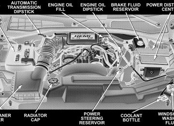
䡵 Engine Compartment 3.7L V6 . . . . . . . . . . . . . . 304
䡵 Engine Compartment 4.7L V-8 . . . . . . . . . . . . . . 305
䡵 Engine Compartment 5.7L HEMI V-8 . . . . . . . . . 306
䡵 Onboard Diagnostic System — OBD II . . . . . . . . 307
▫ Loose Fuel Filler Cap Message . . . . . . . . . . . . 307䡵 Emissions Inspection And Maintenance
Programs
. . . . . . . . . . . . . . . . . . . . . . . . . . . . 308
䡵 Replacement Parts . . . . . . . . . . . . . . . . . . . . . . 309
䡵 Dealer Service . . . . . . . . . . . . . . . . . . . . . . . . . 310䡵 Maintenance Procedures . . . . . . . . . . . . . . . . . . 310
▫ Engine Oil . . . . . . . . . . . . . . . . . . . . . . . . . . 311
▫ Engine Oil Filter . . . . . . . . . . . . . . . . . . . . . . 314
▫ Drive Belts — Check Condition AndTensioner . . . . . . . . . . . . . . . . . . . . . . . . . . . 315
▫ Spark Plugs . . . . . . . . . . . . . . . . . . . . . . . . . 315
▫ Ignition Cables . . . . . . . . . . . . . . . . . . . . . . . 316
▫ Engine Air Cleaner Filter . . . . . . . . . . . . . . . . 316
▫ Engine Fuel Filter . . . . . . . . . . . . . . . . . . . . . 316302 MAINTAINING YOUR VEHICLE
▫ Catalytic Converter . . . . . . . . . . . . . . . . . . . . 317
▫ Maintenance-Free Battery . . . . . . . . . . . . . . . . 318
▫ Air Conditioner Maintenance . . . . . . . . . . . . . 319
▫ Power Steering — Fluid Check . . . . . . . . . . . . 320
▫ Front Suspension Ball Joints . . . . . . . . . . . . . . 321
▫ Drive Shaft Constant Velocity Joints . . . . . . . . 321
▫ Body Lubrication . . . . . . . . . . . . . . . . . . . . . 321
▫ Windshield Wiper Blades . . . . . . . . . . . . . . . . 322
▫ Windshield Washers . . . . . . . . . . . . . . . . . . . 322
▫ Exhaust System . . . . . . . . . . . . . . . . . . . . . . 323
▫ Cooling System . . . . . . . . . . . . . . . . . . . . . . . 324
▫ Emission Related Components . . . . . . . . . . . . 329
▫ Brake System . . . . . . . . . . . . . . . . . . . . . . . . 330▫ Automatic Transmission . . . . . . . . . . . . . . . . 332
▫ Transfer Case . . . . . . . . . . . . . . . . . . . . . . . . 335
▫ Axles . . . . . . . . . . . . . . . . . . . . . . . . . . . . . . 335
▫ Selection Of Lubricating Grease . . . . . . . . . . . 336
▫ Appearance Care And Protection FromCorrosion . . . . . . . . . . . . . . . . . . . . . . . . . . . 337
䡵 Power Distribution Center (Fuse/Relay) . . . . . . . 341
䡵 Fuse Block . . . . . . . . . . . . . . . . . . . . . . . . . . . . 341
▫ Interior Fuses . . . . . . . . . . . . . . . . . . . . . . . . 342
▫ Underhood Fuses (Power Distribution Center) . 345
▫ Underhood Fuses (Integrated Power Module) . 347
. . . . . . . . . . . . . . . . . 348
. . . . . . . . . . . . . . . . . . . . . . 349䡵 Replacement Light Bulbs 䡵 Bulb Replacement
▫ Headlights/Parking/Turn Signal ▫ Rear Side Marker, Tail Lights, Turn Signals And
. . . . . . . . . . 349
Backup Lights — Replacement . . . . . . . . . . . . 350
▫ License Lights . . . . . . . . . . . . . . . . . . . . . . . . 354
▫ Center High-Mounted Stoplight . . . . . . . . . . . 355
▫ Fog Lights . . . . . . . . . . . . . . . . . . . . . . . . . . 356MAINTAINING YOUR VEHICLE 303
䡵 Fluids And Capacities 䡵 Recommended Fluids, Lubricants And Genuine
. . . . . . . . . . . . . . . . . . . 357
Parts . . . . . . . . . . . . . . . . . . . . . . . . . . . . . . . . 359
▫ Engine . . . . . . . . . . . . . . . . . . . . . . . . . . . . . 359
▫ Chassis . . . . . . . . . . . . . . . . . . . . . . . . . . . . 360304 MAINTAINING YOUR VEHICLE
ENGINE COMPARTMENT 3.7L V6
ENGINE COMPARTMENT 4.7L V-8
MAINTAINING YOUR VEHICLE 305
306 MAINTAINING YOUR VEHICLE
ENGINE COMPARTMENT 5.7L HEMI V-8
ONBOARD DIAGNOSTIC SYSTEM — OBD II Your vehicle is equipped with a sophisticated onboard diagnostic system called OBD II. This system monitors the performance of the emissions, engine, and automatic transmission control systems. When these systems are operating properly, your vehicle will provide excellent performance and fuel economy, as well as engine emis- sions well within current government regulations. If any of these systems require service, the OBD II system will turn on the “Malfunction Indicator Light.” It will also store diagnostic codes and other information to assist your service technician in making repairs. Al- though your vehicle will usually be drivable and not need towing, see your dealer for service as soon as possible.
MAINTAINING YOUR VEHICLE 307
CAUTION!
• Prolonged driving with the “Malfunction Indica- tor Light” on could cause further damage to the emission control system. It could also affect fuel economy and driveability. The vehicle must be serviced before any emissions tests can be per- formed. • If the “Malfunction Indicator Light” is flashing while the engine is running, severe catalytic con- verter damage and power loss will soon occur. Immediate service is required.
Loose Fuel Filler Cap Message After fuel is added, the vehicle diagnostic system can determine if the fuel filler cap is loose, improperly installed, or damaged. A loose fuel filler cap message will be displayed in the instrument cluster. Tighten the gas
308 MAINTAINING YOUR VEHICLE
cap until a ⬙clicking⬙ sound is heard. This is an indication that the gas cap is properly tightened. Press the odometer reset button to turn the message off. If the problem persists, the message will appear the next time the vehicle is started. This might indicate a damaged cap. If the problem is detected twice in a row, the system will turn on the Malfunction Indicator Light (MIL). Resolving the problem will turn the MIL light off.
EMISSIONS INSPECTION AND MAINTENANCE PROGRAMS In some localities, it may be a legal requirement to pass an inspection of your vehicle’s emissions control system. Failure to pass could prevent vehicle registration.
For states which have an I/M (Inspection and Maintenance) requirement, this check verifies the following: the MIL (Malfunction Indicator Lamp)
is functioning and is not on when the engine is running, and that the OBD (On Board Diagnostic) system is ready for testing. Normally, the OBD system will be ready. The OBD system may not be ready if your vehicle was recently serviced, if you recently had a dead battery, or a battery replacement. If the OBD system should be determined not ready for the I/M test, your vehicle may fail the test. Your vehicle has a simple ignition key actuated test which you can use prior to going to the test station. To check if your vehicle’s OBD system is ready, you must do the following: 1. Insert your ignition key into the ignition switch. 2. Turn the ignition to the ON position, but do not crank or start the engine. 3. If you crank or start the engine, you will have to start this test over.
4. As soon as you turn your key to the ON position, you will see your MIL symbol come on as part of a normal bulb check. 5. Approximately 15 seconds later, one of two things will happen:
a. The MIL light will blink for approximately 5 sec- onds and then remain on until the first engine crank or the key is turned off. This means that your vehicle’s OBD system is not ready and you should not proceed to the I/M station. b. The MIL light will remain fully illuminated until the first engine crank or the key is turned off. This means that your vehicle’s OBD system is ready and you can proceed to the I/M station.
If your OBD system is not ready, you should see your dealer or repair facility. If your vehicle was recently serviced or had a battery failure or replacement, you may
MAINTAINING YOUR VEHICLE 309
need to do nothing more than drive your vehicle as you normally would in order for your OBD system to update. A recheck with the above test routine may then indicate that the system is now ready. Regardless of whether your vehicle’s OBD system is ready or not ready, if the MIL symbol is illuminated during normal vehicle operation, you should have your vehicle serviced before going to the I/M station. The I/M station can fail your vehicle because the MIL symbol is on with the engine running.
REPLACEMENT PARTS Use of genuine Mopar威 parts for normal/scheduled maintenance and repairs is highly recommended to in- sure the designed performance. Damage or failures caused by the use of non-Mopar威 parts for maintenance and repairs will not be covered by the manufacturer’s warranty.
310 MAINTAINING YOUR VEHICLE
DEALER SERVICE Your dealer has the qualified service personnel, special tools and equipment to perform all service operations in an expert manner. Service manuals are available which include detailed service information for your vehicle. Refer to these manuals before attempting any procedure yourself. NOTE: systems can result against you.
Intentional tampering with emissions control in civil penalties being assessed
WARNING!
You can be badly injured working on or around a motor vehicle. Do only that service work for which you have the knowledge and the proper equipment. If you have any doubt about your ability to perform a service job, take your vehicle to a competent mechanic.
MAINTENANCE PROCEDURES The pages that follow contain the required maintenance services determined by the engineers who designed your vehicle. Besides the maintenance items for which there are fixed maintenance intervals, there are other items that should operate satisfactorily without periodic maintenance. However, if a malfunction of these items does occur, it could adversely affect the engine or vehicle performance. These items should be inspected if a malfunction is observed or suspected.
MAINTAINING YOUR VEHICLE 311
7. Add oil only if the level is below the “SAFE” range (at or below the “ADD” mark) on the engine oil level indicator (dipstick). Adding one quart of oil when the reading is at the ADD mark will result in a reading at the top of the SAFE range..
Engine Oil
Checking Engine Oil Level To assure proper lubrication of your vehicle’s engine, the engine oil must be maintained at the correct level. The best time to check the engine oil level is about 5 minutes after a fully warmed up engine is shut off or before starting the engine after it has sat overnight. 1. Position the vehicle on a level surface. 2. Turn Off the engine and allow approximately 5 min- utes for the oil to settle to the bottom of the crankcase. 3. Remove the engine oil level indicator (dipstick). 4. Wipe the engine oil level indicator (dipstick) clean. 5. Install the engine oil level indicator (dipstick) and make sure it is seated in the tube. 6. Remove the engine oil level indicator (dipstick), keep- ing the handle above the tip, and read the oil level on the engine oil level indicator (dipstick).
312 MAINTAINING YOUR VEHICLE
CAUTION!
Overfilling or underfilling the crankcase will cause oil aeration or loss of oil pressure. This could dam- age your engine.
Frequency Of Oil Change Road conditions and your style of driving affect the interval at which your oil should be changed. Check the following to determine if ANY apply to you: • Day or night temperatures are below 32°F (0°C). • Stop and Go driving. • Extensive engine idling. • Driving in dusty conditions. • Short trips of less than 10 miles (16.2 km).
speeds during hot weather, above 90°F (32°C).
• More than 50% of your driving is at sustained high • Trailer towing, Taxi, Police or delivery service (com- • Off-Road or desert operation. • If equipped for and operating with E-85 (ethanol)
mercial service).
fuel.
If ANY of these apply to you then change your NOTE: engine oil every 3,000 miles (5 000 km) or 3 months, whichever comes first and follow schedule “B” of the ⬙Maintenance Schedules⬙ section of this manual. If none of these apply to you, then change your engine oil at every interval shown on schedule ⬙A⬙ of the ⬙Mainte- nance Schedules⬙ section of this manual.