- 2011 Dodge Durango Owners Manuals
- Dodge Durango Owners Manuals
- 2008 Dodge Durango Owners Manuals
- Dodge Durango Owners Manuals
- 2009 Dodge Durango Owners Manuals
- Dodge Durango Owners Manuals
- 2007 Dodge Durango Owners Manuals
- Dodge Durango Owners Manuals
- 2004 Dodge Durango Owners Manuals
- Dodge Durango Owners Manuals
- 2013 Dodge Durango Owners Manuals
- Dodge Durango Owners Manuals
- 2005 Dodge Durango Owners Manuals
- Dodge Durango Owners Manuals
- 2006 Dodge Durango Owners Manuals
- Dodge Durango Owners Manuals
- 2012 Dodge Durango Owners Manuals
- Dodge Durango Owners Manuals
- Download PDF Manual
-
vehicle or other object. Use your inside mirror when judging the size or distance of a vehicle seen in the right side mirror.
Illuminated Vanity Mirrors — If Equipped An illuminated vanity mirror is on each sun visor. To use the mirror, rotate the sun visor down and swing the mirror cover upward. The lights will turn on automati- cally. Closing the mirror cover turns off the light.
UNDERSTANDING THE FEATURES OF YOUR VEHICLE 77
Heated Mirrors — If Equipped Heated mirrors are automatically activated when you depress the rear window defroster switch located on the instrument panel. The light will illuminate to indicate that the heating elements are ON. Turning OFF the ignition will deactivate the heated mirrors.
78 UNDERSTANDING THE FEATURES OF YOUR VEHICLE
Automatic Dimming Driver’s Exterior Mirror — If Equipped This mirror will automatically adjust for annoying light glare from vehicles behind you. This feature is controlled by the inside mirror and can be turned off by pressing the button at the base of the inside mirror.
HANDS–FREE COMMUNICATION (UConnect™) — IF EQUIPPED UConnect™ is a voice-activated, hands-free, in vehicle communications system. UConnect™ allows you to dial a phone number with your cellular phone* using simple voice commands (e.g., ⬙Call ѧ Mike ѧWork⬙ or ⬙Dial ѧ 248-555-1212⬙). Your cellular phone’s audio is transmitted through your vehicle’s audio system; the system will automatically mute your radio when using the UCon- nect™ system.
the UConnect website
NOTE: The UConnect™ system use requires a cellular phone equipped with the Bluetooth ⬙Hands-Free Profile,⬙ version 0.96 or higher. For UConnect Customer Support call 1-877-855-8400 or visit (www.chrysler.com/ uconnect). UConnect™ allows you to transfer calls between the system and your cellular phone as you enter or exit your vehicle, and enables you to mute the system’s micro- phone for private conversation. The UConnect™ phonebook enables you to store up to 32
names and four numbers per name. Each language has a separate 32 name phonebook accessible only in that language. This system is driven through your Blue- tooth™ Hands-Free profile cellular phone. UConnect™ features Bluetooth™ technology - the global standard that enables different electronic devices to connect toeach other without wires or a docking station, so UCon- nect works no matter where you stow your cellular phone (be it your purse, pocket, or briefcase), as long as your phone is turned on and has been paired to the vehicle’s UConnect™ system. The UConnect™ system allows up to seven cellular phones to be linked to system. Only one linked (or paired) cellular phone can be used with the system at a time. The system is available in English, Spanish, or French languages (as equipped). The rearview mirror contains the microphone for the system and the control buttons that will enable you to access the system. The diagram below shows the mirror with the appropriate buttons. Individual button behavior is discussed in the ⬙Operation⬙ section.
UNDERSTANDING THE FEATURES OF YOUR VEHICLE 79
UConnect™ Switches
The UConnect™ system can be used with any Hands- Free Profile certified Bluetooth™ cellular phone. If your cellular phone supports a different profile (eg., Headset Profile), you may not be able to use any UConnect™ features. Refer to your cellular service provider or the phone manufacturer for details.
80 UNDERSTANDING THE FEATURES OF YOUR VEHICLE
The UConnect™ system is fully integrated with the vehicle’s audio system. The volume of the UConnect™ system can either be adjusted from the radio volume control knob, or from the steering wheel radio control (right switch), if so equipped. The radio display will be used for visual prompts from the UConnect™ system such as ⬙CELL⬙ or caller ID on certain radios. Operation Voice commands can be used to operate the UConnect™ system and to navigate through the UConnect™ menu structure. Voice commands are required after most UConnect™ system prompts. You will be prompted for a specific command and then guided through the available options. • Prior to giving a voice command, one must wait for the voice on beep, which follows the ⬙Ready⬙ prompt or another prompt.
• For certain operations, compound commands can be used. For example, instead of saying ⬙Setup⬙ and then ⬙Phone Pairing,⬙ the following compound command can be said: ⬙Setup Phone Pairing.⬙ • For each of the feature explanation in this section, only the combined form of the voice command is given. You can also break the commands into parts and say each part of the command, when you are asked for it. For example, you can either use the combined form voice command ⬙Phonebook New Entry,⬙ or you can break the combined form command into two voice commands: ⬙Phonebook⬙ and ⬙New Entry.⬙ Please re- member, the UConnect™ system works best when you talk in a normal conversational tone, as if speaking to some one sitting eight feet away from you.
Voice Command Tree Refer to “Voice Tree” at the end of this section.
Help Command If you need assistance at any prompt or if you want to know what your options are at any prompt, say ⬙Help⬙ following the voice on beep. The UConnect™ system will play all the options at any prompt if you ask for help. To activate the UConnect™ system from idle, simply press the ’Phone’ button and follow audible prompts for directions. All UConnect™ system sessions begin with a press of the ’Phone’ button on the mirror. Cancel Command At any prompt, after the voice on beep, you can say ⬙Cancel⬙ and you will be returned to the main menu. However, in a few instances the system will take you back to the previous menu. Pair (Link) UConnect™ System to a Cellular Phone To begin using your UConnect™ system, you must pair your compatible Bluetooth™ enabled cellular phone (re- fer to ⬙Introduction⬙ section to learn about the phone
UNDERSTANDING THE FEATURES OF YOUR VEHICLE 81
type). To complete the pairing process, you will need to reference your cellular phone owner’s manual. One of the following vehicle specific websites may also provide detailed instructions for pairing with the brand of phone that you have: NOTE: • www.chrysler.com/uconnect • www.dodge.com/uconnect • www.jeep.com/uconnect The following are general phone to UConnect™ System pairing instructions: • Press the ’Phone’ button to begin. • After the ⬙Ready⬙ prompt and the following beep, say • When prompted, after the voice on beep, say ⬙Pair a
⬙Setup Phone Pairing.⬙
Phone.⬙
82 UNDERSTANDING THE FEATURES OF YOUR VEHICLE
• You will be asked to say a four-digit pin number which you will later need to enter into your cellular. You can enter any four-digit pin number. You will not need to remember this pin number after the initial pairing process. • The UConnect™ system will then prompt you to begin the cellular phone pairing process on your cellular phone. Before attempting to pair phone, please see your cellular phone’s user manual (Bluetooth section) for instructions on how to complete this step. • For identification purposes, you will be prompted to give the UConnect™ system a name for your cellular phone. Each cellular phone that is paired should be given a unique phone name. • You will then be asked to give your cellular phone a priority level between 1 and 7, 1 being the highest priority. You can pair up to seven cellular phones to your UConnect™ system. However, at any given time,
only one cellular phone can be in use, connected to your UConnect™ System. The priority allows the UConnect™ system to know which cellular phone to use if multiple cellular phones are in the vehicle at the same time. For example, if priority 3 and priority 5
phones are present in the vehicle, the UConnect™ system will use the priority 3 cellular phone when you make a call. You can select to use a lower priority cellular phone at any time (refer to ⬙Advanced Phone Connectivity⬙ section).Dial by Saying a Number • Press the ’Phone’ button to begin. • After the ⬙Ready⬙ prompt and the following beep, say • System will prompt you to say the number you want
⬙Dial.⬙
call.
• For example, you can say ⬙234-567-8901.⬙ The phone number that you enter must be of valid length and combination. The UConnect™ limits the user from dialing invalid combination of numbers. For example, 234-567-890 is nine digits long, which is not a valid phone number - the closest valid phone number has ten digits. • The UConnect™ system will confirm the phone num- ber and then dial. The number will appear in the display of certain radios.
Call by Saying a Name • Press the “Phone” button to begin. • After the ⬙Ready⬙ prompt and the following beep, say • System will prompt you to say the name of the person
⬙Call.⬙
you want call.
UNDERSTANDING THE FEATURES OF YOUR VEHICLE 83
• After the ⬙Ready⬙ prompt and the following beep, say the name of the person you want to call. For example, you can say ⬙John Doe,⬙ where John Doe is a previ- ously stored name entry in the UConnect™ phone- book. Refer to section ⬙Add Names to Your UCon- nect™ Phonebook,⬙ to learn how to store a name in the phonebook. • The UConnect™ system will confirm the name and then dial the corresponding phone number, which may appear in the display of certain radios.
Add Names to Your UConnect™ Phonebook NOTE: Adding names to phonebook is recommended when vehicle is not in motion. • Press the “Phone” button to begin. • After the ⬙Ready⬙ prompt and the following beep, say
⬙Phonebook New Entry.⬙
84 UNDERSTANDING THE FEATURES OF YOUR VEHICLE
• When prompted, say the name of the new entry. Use of long names helps the voice recognition and is recom- mended. For example, say ⬙Robert Smith⬙ or ⬙Robert⬙ instead of ⬙Bob.⬙ • When prompted, enter the number designation (e.g.: ⬙Home,⬙ ⬙Work,⬙ ⬙Mobile,⬙ or ⬙Pager⬙). This will allow you to store multiple numbers for each phonebook entry, if desired. • When prompted, recite the phone number for the
phonebook entry that you are adding.
After you are finished adding an entry into the phone- book, you will be given the opportunity to add more phone numbers to the current entry or to return to the main menu. The UConnect™ system will allow you to enter up to 32
names in the phonebook with each name having up tofour associated phone numbers and designations. Each language has a separate 32 name phonebook accessible only in that language. Edit Entries in the UConnect™ Phonebook NOTE: Adding names to phonebook is recommended when vehicle is not in motion. • Press the ’Phone’ button to begin. • After the ⬙Ready⬙ prompt and the following beep, say • You will then be asked for the name of the phonebook • Next, choose the number designation (home, work, • When prompted, recite the new phone number for the
mobile, or pager) that you wish to edit.
entry that you wish to edit.
⬙Phonebook Edit.⬙
phonebook entry that you are editing.
After you are finished editing an entry in the phonebook, you will be given the opportunities to edit another entry in the phonebook, call the number you just edited, or return to the main menu. ⬙Phonebook Edit⬙ can be used to add another phone number to a name entry that already exists in the phonebook. For example, the entry John Doe may have a mobile and a home number, but you can add John Doe’s work number later using the ⬙Phonebook Edit⬙ feature. Delete Entries in the UConnect™ Phonebook • Press the ’Phone’ button to begin. • After the ⬙Ready⬙ prompt and the following beep, say • After you enter the Phonebook Delete menu, you will then be asked for the name of the entry that you wish to delete. You can either say the name of a phonebook entry that you wish to delete or you can say ⬙List
⬙Phonebook Delete.⬙
UNDERSTANDING THE FEATURES OF YOUR VEHICLE 85
Names⬙ to hear a list of the entries in the phonebook from which you choose. To select one of the entries from the list, press the ⬙Voice Recognition⬙ button while the UConnect™ system is playing the desired entry and say ⬙Delete.⬙ • After you enter the name, the UConnect™ system will ask you which designation you wish to delete: home, work, mobile or pager. Say the designation you wish to delete.
After confirmation, the phonebook entries will be de- leted. Note that only the phonebook in the current language is deleted. Delete All Entries in the UConnect™ Phonebook • Press the ’Phone’ button to begin. • After the ⬙Ready⬙ prompt and the following beep, say
⬙Phonebook Erase All.⬙
86 UNDERSTANDING THE FEATURES OF YOUR VEHICLE
• The UConnect™ system will ask you to verify that you • After confirmation, the phonebook entries will be
wish to delete all the entries from the phonebook.
deleted.
⬙Phonebook List Names.⬙
List All Names in the UConnect™ Phonebook • Press the ’Phone’ button to begin. • After the ⬙Ready⬙ prompt and the following beep, say • The UConnect™ system will play the names of all the • To call one of the names in the list, press the ⬙Voice Recognition’ button during the playing of the desired name and say ⬙Call⬙. NOTE: the user can also exercise ⬙Edit⬙ or ⬙Delete⬙ operations at this point. • The UConnect™ system will then prompt you as to
phonebook entries.
number designation you wish to call.
• The selected number will be dialed. Phone Call Features The following features can be accessed through the UConnect™ system if the feature(s) are available on your cellular service plan. For example, if your cellular service plan provides three-way calling, this feature can be accessed through the UConnect™ system. Check with your cellular service provider for the features that you have. Answer or Reject an Incoming Call - No Call Currently in Progress When you receive a call on your cellular phone, the UConnect™ system will the vehicle audio system, if on, and will ask if you would like to answer the call. To reject the call, press and hold the ’Phone’ button until you hear a single beep indicating that the incoming call was rejected.
interrupt
Answer or Reject an Incoming Call - Call Currently in Progress If a call is currently in progress and you have another incoming call, you will hear the same network tones for call waiting that you normally hear when using your cell phone. Press the ’Phone’ button to place the current call on hold and answer the incoming call. NOTE: The UConnect™ system compatible phones in market today do not support rejecting an incoming call when another call is in progress. Therefore, the user can only either answer an incoming call or ignore it. Making a Second Call while Current Call in Progress To make a second call while you are currently in a call, press the ’Voice Recognition’ button and say ⬙Dial⬙ or ⬙Call⬙ followed by the phone number or phonebook entry you wish to call. The first call will be on hold while the
UNDERSTANDING THE FEATURES OF YOUR VEHICLE 87
second call is in progress. To go back to the first call, refer to section ⬙Toggling Between Two Calls.⬙ To combine two calls, refer to section ⬙Conference Call.⬙ Place/Retrieve a Call from Hold To put a call on hold, press the ⬘Phone’ button until you hear a single beep which will indicate that the call has been placed on hold. To bring the call back from hold, press and hold the ⬘Phone’ button until you hear a single beep. Toggling Between Calls If two calls are in progress (one active and one on hold), press the ’Phone’ button until you hear a single beep indicating that the active and hold status of the two calls have switched. Only one call can be placed on hold at one time.
88 UNDERSTANDING THE FEATURES OF YOUR VEHICLE
Conference Call When two calls are in progress (one active and one on hold), press and hold the ’Phone’ button until you hear a double beep indicating that the two calls have been joined into one conference call. Three-Way Calling To initiate three-way calling, press the ’Voice Recogni- tion’ button while a call is in progress and make a second phone call as described in section ⬙Making a Second Call while Current Call in Progress.⬙ After the second call has established, press and hold the ’Phone’ button until you hear a double beep indicating that the two calls have been joined into one conference call. Call Termination To end a call in progress, momentarily press the ⬘Phone’ button. Only the active call(s) will be terminated and if there is a call on hold, it will become the new active call.
⬙Redial.⬙
Redial • Press the ’Phone’ button to begin. • After the ⬙Ready⬙ prompt and the following beep, say • The UConnect™ system will call the last number that was dialed on your cellular phone. Note: this may not be the last number dialed from the UConnect™ sys- tem.
Call Continuation Call continuation is progression of a phone call on UConnect™ system after the vehicle ignition key has been switched to off. Call continuation functionality available on the vehicle can be any one of three types: • After ignition key is switched off, a call can continue on the UConnect™ system either until the call ends or
until the vehicle battery condition dictates cessation of the call on the UConnect™ system and transfer of the call to the mobile phone. • After ignition key is switched to off, a call can continue on the UConnect™ system for certain duration, after which the call is automatically transferred from the UConnect™ system to the mobile phone.
• An active call
is automatically transferred to the
mobile phone after ignition key is switched to off.
UConnect™ System Features
Language Selection To change the language that the UConnect™ system is using, • Press the ’Phone’ button to begin.
UNDERSTANDING THE FEATURES OF YOUR VEHICLE 89
• After the ⬙Ready⬙ prompt and the following beep, say the name of the language you wish to switch to (English, Espanol, or Francais, if so equipped). • Continue to follow the system prompts to complete
language selection.
After selecting one of the languages, all prompts and voice commands will be in that language. NOTE: After every UConnect™ language change op- eration, only the language specific 32 name phonebook is usable. The phone pairing is not language specific and usable across all languages. Emergency Assistance If you are in an emergency and the mobile phone is reachable: • Pick up the phone and manually dial the emergency
number for your area.
90 UNDERSTANDING THE FEATURES OF YOUR VEHICLE
If the phone is not reachable and the UConnect™ system is operational, you may reach the emergency number as follows: • Press the ’Phone’ button to begin. • After the ⬙Ready⬙ prompt and the following beep, say ⬙Emergency⬙ and the UConnect™ system will instruct the paired cellular phone to call the emergency num- ber. This feature is only supported in the USA.
NOTE: The emergency number dialed is based on the Country where the vehicle is purchased (911 for USA/ Canada and 060 for Mexico). The number called may not be applicable with the available cellular service and area. The UConnect™ system does slightly lower your chances of successfully making a phone call as to that for the cell phone directly. Your phone must be turned on and paired to the UCon- nect™ system to allow use of this vehicle feature in
emergency situations when the cell phone has network coverage and stays paired to the UConnect™ system. Towing Assistance If you need towing assistance, • Press the ’Phone’ button to begin. • After the ⬙Ready⬙ prompt and the following beep, say
⬙Towing Assistance.⬙
NOTE: The Towing Assistance number dialed is based on the Country where the vehicle is purchased (1-800- 528-2069 for USA, 1-877-213-4525 for Canada, 55-14-3454
for Mexico city and 1-800-712-3040 for outside Mexico city in Mexico). Please refer to the 24-Hour Towing Assistance coverage details in the DaimlerChrysler Corporation 24-Hour Towing Assistance Program Guide.Paging To learn how to page, refer to section ⬙Working with Automated Systems.⬙ Paging works properly except for pagers of certain companies which time-out a little too soon to work properly with the UConnect™ system. Voice Mail Calling To learn how to access your voice mail, refer to section ⬙Working with Automated Systems.⬙ Working with Automated Systems This method is designed to be used in instances where one generally has to press numbers on the cellular phone keypad while navigating through an automated tele- phone system. You can use your UConnect™ system to access a voice- mail system or an automated service, such as, paging service or automated customer service. Some services require immediate response selection, in some instances, that may be too quick for use of UConnect™ system.
UNDERSTANDING THE FEATURES OF YOUR VEHICLE 91
When calling a number with your UConnect™ system that normally requires you to enter in a touch-tone sequence on your cellular phone keypad, you can push the ’Voice Recognition’ button and say the sequence you wish to enter followed by the word ⬙Send.⬙ For example, if required to enter your pin number followed with a pound 3 7 4 6 #, you can press the ’Voice Recognition’ button and say ⬙3 7 4 6 # Send.⬙ Saying a number, or sequence of numbers, followed by ⬙Send⬙ is also to be used to navigate through an automated customer service center menu structure and to leave a number on a pager. Barge In - Overriding Prompts The ’Voice Recognition’ button can be used when you wish to skip part of a prompt and issue your voice recognition command immediately. For example, if a prompt is playing ⬙Would you like to pair a phone, clear aѧ,⬙ you could press the ’Voice Recognition’ button and say ⬙Pair a Phone⬙ to select that option without having to listen to the rest of the voice prompt.
92 UNDERSTANDING THE FEATURES OF YOUR VEHICLE
Turning Confirmation Prompts On/Off Turning confirmation prompts off will stop the system from confirming your choices (e.g. the UConnect™ sys- tem will not repeat a phone number before you dial it). • Press the ’Phone’ button to begin. • After the ⬙Ready⬙ prompt and the following beep, say ⬙Setup Confirmations.⬙ The UConnect™ system will play the current confirmation prompt status and you will be given the choice to change it. Phone and Network Status Indicators The UConnect™ system will provide notification to inform you if your cellular phone is in roaming status, has low signal strength, or has a low battery when you are trying to place a phone call. Dialing Using the Cellular Phone Keypad You can dial a phone number with your cellular phone keypad and still use the UConnect™ system (while
dialing via the cell phone keypad, the user must exercise caution and take precautionary safety measures). By dialing a number with your paired Bluetooth™ cellular phone, the audio will be played through your vehicle’s audio system. The UConnect™ system will work the same as if you dial the number using voice recognition. NOTE: Certain brands of mobile phones do not send the dial ring to the UConnect™ system to play it on the vehicle audio system, so you will not hear it. Under this situation, after successfully dialing a number, the user may feel that the call did not go through even though the call is in progress. Once your call is answered, you will hear the audio. Mute/Un-mute (Mute off) When you mute the UConnect™ system, you will still be able to hear the conversation coming from the other party, but the other party will not be able to hear you. In order to mute the UConnect™ system:
• Press the ’Voice Recognition’ button. • After the ⬙Ready⬙ prompt and the following beep, say
⬙Mute.⬙
In order to un-mute the UConnect™ system: • Press the ’Voice Recognition’ button. • After the ⬙Ready⬙ prompt and the following beep, say
⬙Mute-off.⬙
Information Service When using AT&T Wireless Service, dialing to phone number ⬙#121,⬙ you can access voice activated automated system to receive news, weather, stocks, traffic, etc. related information.
UNDERSTANDING THE FEATURES OF YOUR VEHICLE 93
Advanced Phone Connectivity
Transfer Call to and from Cellular Phone The UConnect™ system allows on going calls to be transferred to your cellular phone to the UConnect™ system without terminating the call. To transfer an ongo- ing call from your UConnect™ paired cellular phone to the UConnect™ system or vice-versa, press the ’Voice Recognition’ button and say ⬙Transfer Call.⬙ Connect or Disconnect Link Between the UConnect™ System and Cellular Phone Your cellular phone can be paired with many different electronic devices, but can only be actively ⬙connected⬙ with one electronic device at a time. If you would like to connect or disconnect the Blue- tooth™ connection between a UConnect™ paired cellular phone and the UConnect™ system, follow the instruction described in your cellular phone user’s manual.
94 UNDERSTANDING THE FEATURES OF YOUR VEHICLE
“Setup Phone pairing”.
List Paired Cellular Phone Names • Press the ’Phone’ button to begin. • After the “Ready” prompt and the following beep, say • When prompted, say ⬙List Phones⬙. • The UConnect™ system will play the phone names of all paired cellular phones in order from the highest to the lowest priority. To “select” or “delete” a paired phone being announced, press the ⬘Voice recognition’ button and say “Select” or “Delete”. Also, see next two sections for alternate way of doing this.
Select another Cellular Phone This feature allows you to select and start using another phone with the UConnect™ system. The phone must have been previously paired to the UConnect™ system that you want to use it with.
be played.
⬙Setup Select Phone.⬙
• Press the ’Phone’ button to begin. • After the ⬙Ready⬙ prompt and the following beep, say • The phone names (along with priority numbers) will • When prompted say the priority number of the cellu- lar phone you wish to select. You can also press the ⬘Voice Recognition’ button anytime while the list is being played and say the priority number. • The selected phone will be used for the next phone call. If the selected phone is not available, the UCon- nect™ system will return to using the highest priority phone present in or near (approximately with in 30
feet) the vehicle.Delete UConnect™ Paired Cellular Phones • Press the ’Phone’ button to begin.
⬙Setup Phone Pairing.⬙
• After the ⬙Ready⬙ prompt and the following beep, say • At the next prompt, say ⬙Delete.⬙ • The phone names (along with priority numbers) will • When prompted say the priority number of the cellu- lar phone (or “All” to delete all phones) you wish to delete. You can also press the ⬘Voice Recognition’ button anytime while the list is being played and say the priority number.
be played.
Things You Should Know About Your UConnect™ System
Voice Recognition (VR) • Always wait for the beep before speaking.
UNDERSTANDING THE FEATURES OF YOUR VEHICLE 95
• Speak normally, without pausing, just as you would speak to a person sitting approximately eight (8) feet away from you. • Make sure that no one other than you is speaking during a voice recognition period. • Performance is maximized under: • low-to-medium blower setting, • low-to-medium vehicle speed, • low road noise, • smooth road surface, • fully closed windows, • dry weather condition. • Even though the system is designed for users speaking in North American English and Spanish accents, the system may not always work for some.
96 UNDERSTANDING THE FEATURES OF YOUR VEHICLE
motion is recommended.
names in the UConnect™ phonebook.
• When navigating through an automated system, such as, voice mail, or when sending a page, at the end of speaking the digit string, make sure to say ⬙send.⬙ • Storing names in phonebook when vehicle is not in • It is not recommended to store similar sounding • UConnect™ phonebook name tag recognition rate is optimized for the person who stored the name in the phonebook. • You can say ⬙O⬙ (letter ⬙O⬙) for ⬙0⬙ (zero). ⬙800⬙ must be • Even though international dialing for most number combinations is supported, some shortcut dialing number combinations may not be supported.
spoken ⬙eight-zero-zero.⬙
Far End Audio Performance • Audio quality is maximized under: • low-to-medium blower setting, • low-to-medium vehicle speed, • low road noise, • smooth road surface, • fully closed windows, and • dry weather condition. • Operation from driver seat. • Performance, such as, audio clarity, echo. and loud- ness to a large degree, rely on the phone and network, and not the UConnect™ system. • Echo at far end can sometime be reduced by lowering
the in-vehicle audio volume.
Bluetooth Communication Link Cellular phones have been found to occasionally loose connection to the UConnect™ system. When this hap- pens, the connection can generally be re-established by switching the phone off/on. Your cell phone is recom- mended to remain in Bluetooth ⬙on⬙ mode. Reset In rare instances, it may be necessary to reset the UCon- nect™ system. The reset feature is exercised by pressing
UNDERSTANDING THE FEATURES OF YOUR VEHICLE 97
and holding the ’UConnect™ ’ and ’Voice Recognition’ buttons simultaneously for 15 seconds. Normally, you do not need to exercise this feature. Power-Up After switching ignition key from off to either On or ACC position, or after a reset, you must wait at least five (5) seconds prior to using the system.
98 UNDERSTANDING THE FEATURES OF YOUR VEHICLE
UNDERSTANDING THE FEATURES OF YOUR VEHICLE 99
100 UNDERSTANDING THE FEATURES OF YOUR VEHICLE
Primary Zero Add location All Confirmation prompts Delete a name Language List names
North American English Alternate(s) Oh Add new All of them Confirmations prompts Delete Select language List all
UNDERSTANDING THE FEATURES OF YOUR VEHICLE 101
List paired phones Pager Phone pairing Phonebook Return to main menu Select phone Set up
List phones Beeper Pairing Phone book Return. Main menu select Phone settings phone set up
102 UNDERSTANDING THE FEATURES OF YOUR VEHICLE
SEATS
Front Seat Manual Seat Adjustment The adjusting lever is at the front of the seat, near the floor. Lift the lever and move the seat to the desired position. Release the bar to lock the seat into position. Using body pressure, move forward and rearward on the seat to be sure the seat adjusters have latched.
WARNING!
Adjusting a seat while the vehicle is moving is dangerous. The sudden movement of the seat could cause you to lose control. The seat belt might not be properly adjusted and you could be injured. Adjust any seat only while the vehicle is parked.
UNDERSTANDING THE FEATURES OF YOUR VEHICLE 103
Manual Lumbar Support Adjustment — If Equipped The manual lumbar support adjustment lever is located on the right side of the driver’s seat and on the left side of the passenger’s seat. Moving the lumbar control lever fore and aft increases or decreases the lumbar support.
Front Seats Manual Seat Recliners The bucket seats are equipped with recliners. The reclin- ing mechanism is operated by a lever located on the right side of the passenger’s seat and the left side of the driver’s seat. To recline, lean forward slightly before lifting the lever, then push back to the desired position and release the lever. Lean forward and lift the lever to return the seatback to its normal position. Using body pressure, lean forward and rearward on the seat to be sure the seatback is locked.
WARNING!
Do not ride with the seatback reclined so that the shoulder belt is no longer resting against your chest. In a collision you could slide under the seat belt and be seriously or even fatally injured. Use the recliner only when the vehicle is parked.
104 UNDERSTANDING THE FEATURES OF YOUR VEHICLE
Adjustable Head Restraints — All Seating Positions Head restraints can reduce the risk of whiplash injury in the event of impact from the rear. Pull up or push down on the restraints so that the upper edge is as high as practical, at least to the level of the ears. To lower the head restraint, depress the release button located at the base of the head restraint and push down on the head restraint.
8 - Way Driver’s Power Seat — If Equipped The driver’s power seat switches are located on the left side of the driver’s seat lower side trim. The bottom switch controls up/down, forward/rearward, and tilt adjustment. The top switch controls the seatback recline adjustment.
UNDERSTANDING THE FEATURES OF YOUR VEHICLE 105
Front Heated Seats — If Equipped
4 - Way Passenger’s Power Seat — If Equipped The front passenger’s power seat switches are located on the right side of the passenger seat lower side trim. The bottom switch controls forward/rearward adjustment. The top switch controls the seatback recline adjustment. NOTE: The 4 - way seat does not have an up/down adjustment.
This feature heats the driver and front passenger seats. The controls for the front heated seats are located on the center of the instrument panel, below the climate con- trols. The heated seat system allows the driver and front
106 UNDERSTANDING THE FEATURES OF YOUR VEHICLE
passenger to select from two different levels of supple- mental electrical seat heating, or no seat heating to suit their individual comfort requirements. With the ignition switch in the RUN position, depressing the heated seat switch rocker to its momentary High or Low position provides power to the heated seat element and maintains the requested temperature setting. If the heated seat switch is depressed to a different position (Low or High) than the currently selected state, the requested temperature setting will change to a new selection. If the heated seat switch is depressed a second time to the same position as the currently selected state, the seat heater will turn off. NOTE: The high heat setting will operate for approxi- mately a two hour duration. After two hours, the system will automatically transition to the low heat setting. The low heat setting will operate for a two hour duration,
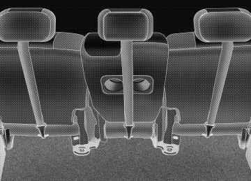
then the system will turn off. Thus, a maximum of four hours of operation until the system is reactivated. If the low heat setting is initially selected, the system will operate for two hours and then turn off. If the indicator lamp on the heated seat switch does not light when the switch is depressed or if heated seats does not operate, the system should be serviced by a qualified technician. Second Row 40/20/40 Seat — Fold and Tumble The 40/20/40 seat configuration is standard on all mod- els. This seat is equipped with a unique fold-and-tumble feature. The 40 % seatbacks have spring loaded hinges which assist with the folding of the seatbacks. Second row leather seats have seatback recliners at the 40% seating positions. Raising the lever allows the seat- back to be reclined an additional 11degrees.
UNDERSTANDING THE FEATURES OF YOUR VEHICLE 107
To fold the 20% seatback, pull the strap forward to release the seatback. Fold the seatback down for use as an armrest or to carry cargo. When returning the seatback to the upright position, push the seatback rearward to latch the seatback. Pull the seatback forward to ensure that it is locked in the upright position.
To Fold the 40% seatbacks fully raise the lever on the side of the seat to release the seatback. The seatback can now be folded into the down position for use as a cargo floor, or the seat can now be tumbled forward to allow access to the rear of the vehicle.
108 UNDERSTANDING THE FEATURES OF YOUR VEHICLE
WARNING!
The 20% seatback contains the center shoulder belt. A 20% seatback that is not fully latched in the upright position will not protect you properly.
To Tumble the 40% seat, fully raise the lever on the side of the seat to release the floor latches and tumble the seat. NOTE: The seatback must be fully folded into the down position to allow the lever to be raised enough to release the floor latches.
UNDERSTANDING THE FEATURES OF YOUR VEHICLE 109
To Fold and Tumble the 2nd row 40% seats from the 3rd row, fully raise the lever at the rear of the seat to fold the seatback. Continue raising the lever to release the floor latches to tumble the seat. NOTE: The head restraints must be lowered but do not have to be removed to fold and tumble the seats. Third Row Seat Bench — If Equipped
To Fold The Seats Folding the third seat occurs in two stages: First the cushion is lifted and moved forward from the pockets at the front of the cushion. The cushion will rest onto the floor directly behind the second row seat. Second, the top of the back is folded forward and rests onto the cushion. The back will not fold unless the cushion has been folded forward first.
110 UNDERSTANDING THE FEATURES OF YOUR VEHICLE
To Achieve Maximum Cargo Capacity Pull the release handles and strap on the second row seats and fold flat. After folding the third row seat, unsnap the flipper panel on the third row seatback and flip it forward on the backs of the second row seats.
NOTE: Before returning the second row 40% seats to their upright position, always snap the third row seat flipper panel(s) back to the third row seat first. NOTE: The seat belt buckles are hinged to fold with the seat back.
WARNING!
Do not sit in the third row seat unless the cushion and back are properly engaged. Proper engagement can be verified by pushing/pulling on the upright seatback. The seatback will not move unless prop- erly engaged. Do not sit in the 3rd row seat with the second row seatback(s) folded or tumbled. In a collision, you could slide under the seat belt and be seriously or even fatally injured.
UNDERSTANDING THE FEATURES OF YOUR VEHICLE 111
Third Seat 50/50 Split Seat — If Equipped
To Fold The Seat(s) Pull up the release handle(s) and move the seatback forward. This can be performed from either the front or rear of the third row seats. The seatback and seat cushion move simultaneously into load floor position and rests
112 UNDERSTANDING THE FEATURES OF YOUR VEHICLE
on the floor behind the second row seats.The seat belt buckles are hinged and fold with the seatbacks.
To Achieve Maximum Cargo Capacity Pull the release handles and strap on the second row seats and fold flat. After folding the third row seats,
unsnap the flipper panels on the back of the third row seatbacks and flip the panels onto the backs of the second row seats. NOTE: Before returning the second row 40% seats the upright position, always reposition the flipper panel(s) and snap onto the third row seat first. NOTE: The seat belt buckles are hinged to fold with the seat backs. To Return The Seat(s) To An Upright Position If required, unsnap the strap(s). Pull on the seatback from the rear of the vehicle to reposition the seat(s) to an upright position. Reposition strap onto the hook and loop material on the seat back and snap strap(s).
WARNING!
Do not sit in the third row seat unless the cushion and back are properly engaged. Proper engagement can be verified by pushing/pulling on the upright seatback. The seatback(s) will not move unless prop- erly engaged. Do not sit in the 3rd row seat(s) with the second row seatback(s) folded or tumbled. In a collision, you could slide under the seat belt and be seriously or even fatally injured.
UNDERSTANDING THE FEATURES OF YOUR VEHICLE 113
114 UNDERSTANDING THE FEATURES OF YOUR VEHICLE
DRIVER MEMORY SYSTEM — IF EQUIPPED Once programmed, the memory buttons 1 and 2 on the driver’s door panel can be used to recall the driver’s seat position, driver’s outside mirror position, adjustable brake and accelerator pedals position, Automatic Tem- perature Control (ATC) temperature and radio station preset settings. Your Remote Keyless Entry transmitters can also be programmed to recall the same positions when the UNLOCK button is pressed.
Your vehicle was delivered with two Remote Keyless Entry transmitters. One or both transmitters can be linked to either memory position. The memory system can accommodate up to two transmitters, each transmit- ter linked to either of the two memory positions.
Setting Memory Positions and Linking Remote Keyless Entry Transmitter to Memory
NOTE: Each time the SET (S) button and a numbered button (1 or 2) are pressed, you erase the memory settings for that button and store new settings. 1. Adjust the driver’s seat, recliner, and both side view mirrors to the desired positions. NOTE: Not all motors may be moved at one time. Please refer to the 8-way power seat description. 2. Adjust the brake and accelerator pedals to the desired positions. 3. Turn on the radio and set the radio station presets (up to 10 AM and 10 FM stations can be set). 4. Adjust while the ATC is in Auto mode.
the Automatic Temperature Control (ATC)
UNDERSTANDING THE FEATURES OF YOUR VEHICLE 115
5. Press and release the SET (S) button located on the driver’s door. 6. Within 5 seconds, press and release memory button 1
or 2 on the driver’s door. The next step must be per- formed within 10 seconds if you desire to also use a Remote Keyless Entry transmitter to recall memory po- sitions. 7. Press and release the LOCK button on one of the transmitters. 8. Insert the ignition key and turn the ignition switch to the ON position. 9. Repeat the above steps to set the next memory posi- tion using the other numbered memory button or to link another Remote Keyless Entry transmitter to memory. NOTE: A chime sound may be heard if Setting Memory was inhibited for any reason.116 UNDERSTANDING THE FEATURES OF YOUR VEHICLE
memory positions.
Memory Position Recall NOTE: • The driver’s seat belt must be unbuckled to recall • The vehicle must be in Park to recall memory posi- • Not all motors may be moved at one time. Please refer
tions.
to the 8-way power seat description.
To recall the memory settings for driver one, press memory button number 1 on the driver’s door or the Unlock button on the Remote Keyless Entry transmitter linked to memory position 1. To recall the memory setting for driver two, press memory button number 2 on the driver’s door or the Unlock button on the Remote Keyless Entry transmitter linked to memory position 2.
A recall can be cancelled by pressing any of the memory buttons on the drivers door during a recall (S, 1, or 2), or pressing any one of the power seat buttons, or pressing the adjustable pedals button, or pressing either the LOCK or UNLOCK button on the remote keyless entry trans- mitter when not in the ignition switch. When a recall is cancelled, the driver’s seat, and the pedals stop moving. A delay of one second will occur before another recall can be selected. NOTE: A chime sound may be heard if Setting Memory was inhibited for any reason. To Disable A Transmitter Linked to Memory
1. Turn the ignition switch to the OFF position and remove the key. 2. Press and release the memory SET (S) button located on the driver’s door.
3. Within 10 seconds, press and release the UNLOCK button on the Remote Keyless Entry transmitter. To disable another transmitter linked to either memory position, repeat steps 1-3 for each transmitter. NOTE: The capability to link Remote Keyless Entry transmitters to memory is enabled when delivered from the factory. The capability to link Remote Keyless Entry transmitters to memory can be disabled (or later reen- abled) by a qualified DaimlerChrysler representative. Self-Limiting Control To improve vehicle reliability, the memory system in- cludes a self-limiting control for full travel positioning of power seat and Adjustable Pedal movement (all direc- tions). This self-limiting control may however develop an unintended movement limitation if an obstruction is encountered at sometime during usage. One example of such an occurrence may include a box or package ob- structing the full rearward movement of the driver’s seat.
UNDERSTANDING THE FEATURES OF YOUR VEHICLE 117
Once the obstruction is removed, the self-limiting control may be restored to maximum position. The self-limiting control may be restored by first reaching the recently limited or obstructed position, then release and reactivate the same button or buttons. Continued seat travel beyond the obstructed position will indicate the recently encoun- tered self-limitation has been cleared. Driver Easy Exit and Easy Entry Control This additional feature provides automatic driver’s seat positioning which will enhance driver mobility out of and into the vehicle. The seat cushion will move rear- ward approximately 2.5 inches (60 mm) when the key is removed from the ignition switch. The seat will move forward approximately 2.5 inches (60 mm) when the key is placed into the ignition and turned out of the LOCK position. Each stored memory setting will have an asso- ciated Easy Exit and Easy Entry position. The Easy Exit and Easy Entry feature may be automatically disabled if
Reverse feature may be enabled (or later disabled) by a qualified DaimlerChrysler service representative.
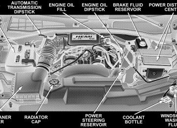
TO OPEN AND CLOSE THE HOOD To open the hood, two latches must be released. First pull the hood release lever located under the left side of the instrument panel.
118 UNDERSTANDING THE FEATURES OF YOUR VEHICLE
the seat is positioned rearward enough and no benefit from moving the seat any farther rearward. NOTE: The Easy Exit Easy Entry feature is not enabled when delivered from the factory. The Easy Exit Easy Entry feature may be enabled (or later disabled) by a qualified DaimlerChrysler service representative. Tilt Mirrors in Reverse This additional feature provides automatic outside mir- ror positioning which will aid the driver’s view of the ground rearward of the front doors. The outside mirrors will move slightly downward from the present position when the vehicle is shifted into Reverse position. The outside mirrors will then return to the original position when the vehicle is shifted out of Reverse position. Each stored memory setting will have an associated Tilt Mir- rors in Reverse position. NOTE: The Tilt Mirrors in Reverse feature is not en- abled when delivered from the factory. The Tilt Mirrors in
Then push the safety latch lever to the left. It is located between the grille and hood opening right of the center.
NOTE: Ensure hood prop rod is fully seated into clip before closing hood to prevent damage to grille.
UNDERSTANDING THE FEATURES OF YOUR VEHICLE 119
WARNING!
If the hood is not fully latched, it could fly up when the vehicle is moving and block your forward vision. Be sure all hood latches are fully latched before driving.
To prevent possible damage, do not slam the hood to close it. Use a firm downward push at the center front edge of the hood to ensure that both latches engage. Never drive your vehicle unless the hood is fully closed, with both latches engaged.
120 UNDERSTANDING THE FEATURES OF YOUR VEHICLE
LIGHTS
Interior Lights
Courtesy and dome lights are turned on when the front doors are opened, when the dimmer control (rotating wheel on the right side of the switch) is rotated to the second upward detent position, or when the UNLOCK button is pressed on the key fob. When a door is open and the interior lights are on, rotating the dimmer control
UNDERSTANDING THE FEATURES OF YOUR VEHICLE 121
all the way down to the OFF detent will cause all the interior lights to go out. This allows the doors to stay open for extended periods of time without discharging the vehicle’s battery. The brightness of the instrument panel lighting can be regulated by rotating the dimmer control up (brighter) or down (dimmer). When the headlights are ON you can supplement the brightness of the odometer, trip odom- eter, radio and overhead console by rotating the control up until you hear a click. This feature is termed the ⬙Parade⬙ mode and is useful when headlights are re- quired during the day. Battery Saver To protect the life of your vehicle’s battery, Load Shed- ding is provided for both the interior and exterior lights. If the ignition is off and any door is left ajar for eight minutes or the dimmer control is rotated upwards for 15
minutes, the interior lights will automatically turn off.122 UNDERSTANDING THE FEATURES OF YOUR VEHICLE
If the headlights remain on while the ignition is cycled off, the exterior lights will automatically turn off after 8
minutes. If the headlights are turned on and left on for 8
minutes while the ignition is off, the exterior lights will automatically turn off. NOTE: Battery Saver mode is cancelled if the ignition is ON. NOTE: While the engine is running, the system will deactivate the Fog Lights and Heated seats if a low battery system voltage is detected. Headlight Delay To aid in your exit, your vehicle is equipped with a headlight delay that will leave the headlights on for 90
seconds. This delay is initiated when the ignition is cycled off while the headlight switch is on, and then the headlight switch is cycled off. The headlights will remainon for 90 seconds. Headlight delay can be cancelled by either turning the headlight switch ON then OFF or by turning the ignition ON. NOTE: This feature can be disabled by your authorized dealer. Automatic Headlights — If Equipped Automatic Headlights can be activated by rotating the rotary headlight switch to the symbol “A.” The head- lights will turn on when the engine is running and the ambient light sensor indicates that the headlights should be activated. The headlights will turn off if the headlight switch is rotated to the off position or 90 seconds after the ignition is turned to OFF.
Headlights, Parking Lights, Panel Lights
When the headlight switch is rotated to the first position to the right, the parking lights, taillights, side marker lights, license plate light and instrument panel lights are all turned on. The headlights will turn ON when the switch is rotated to the second position. Your vehicle is equipped with plastic headlight lenses that are lighter and less susceptible to stone breakage than glass headlights. Plastic is not as scratch resistant as glass and therefore different lens cleaning procedures must be followed. To minimize the possibility of scratching the lenses and reducing light output, avoid wiping with a dry cloth. To remove road dirt, wash with a mild soap solution fol- lowed by rinsing. Do not use abrasive cleaning components, solvents, steel wool or other abrasive materials to clean the lenses.
UNDERSTANDING THE FEATURES OF YOUR VEHICLE 123
Illuminated Entry Headlights turn on for 90 seconds, when the Remote Keyless Entry UNLOCK button is pressed. NOTE: This feature can be activated by your authorized dealer. Daytime Running Lights (Canada Only) The headlights on your Durango will illuminate when the engine is started. This provides a constant “Lights ON” condition until the ignition is turned OFF. The lights illuminate at reduced intensity. If the parking brake is applied the Daytime Running Lights will turn off. If the headlights are activated, the Daytime Running Lights feature will transition to the normal headlight operating mode.
124 UNDERSTANDING THE FEATURES OF YOUR VEHICLE
Lights-on Reminder If the headlights, parking lights, or courtesy lights are left On, after the ignition is turned Off, a continuous fast chime will sound when the driver’s door is opened. Fog Lights — If Equipped
position and pressing the fog light button. The fog lights will operate only when the parking lights are ON or when the vehicle headlights are ON low beam. An indicator light located in the instrument cluster will illuminate when the fog lights are on. The fog lights will turn off when the switch is pressed in, when the head- light switch is rotated to the OFF position, or the high beam is selected.
MULTIFUNCTION CONTROL LEVER The multifunction control lever is located on the left side of the steering column.
The foglights are turned ON by placing the headlight rotary control in the parking light, headlight, or Auto
Turn Signals
Move the lever up or down to signal a right-hand or left-hand turn. The arrow on either side of the instrument cluster flashes to indicate the direction of the turn, and proper operation
UNDERSTANDING THE FEATURES OF YOUR VEHICLE 125
of the front and rear turn signal lights. If an indicator fails to light when the lever is moved, it would suggest that the switch or indicator lamp is defective. If a defective bulb or wiring circuit is detected for the turn signal system, the arrow indicators will flash at a faster rate. You can signal a lane change by moving the lever partially up or down. NOTE: duration, a continuous chime will sound. Passing Light You can signal another vehicle with your headlights by partially pulling the multifunction lever toward the steer- ing wheel. This will cause the high beam headlights to turn on until the lever is released.
If a turn signal has been left on for at least a mile
126 UNDERSTANDING THE FEATURES OF YOUR VEHICLE
High Beam / Low Beam Select Switch Pull the multifunction control lever fully toward the steering wheel to switch the headlights from HIGH or LOW beam.
Windshield Wipers
The wipers and washers are operated by a switch in the multifunction control lever. Turn the end of the handle to select the desired wiper speed. Intermittent Wiper System The intermittent feature of this system was designed for use when weather conditions make a single wiping cycle,
with a variable pause between cycles, desirable. For maximum delay between cycles, rotate the control knob into the upper end of the delay range. The delay interval decreases as you rotate the knob until it enters the LO continual speed position. The delay can be regulated from a maximum of about 15 seconds between cycles, to a cycle every 2 seconds. The delay intervals will double in duration when the vehicle speed is 10 mph (16 km) or less.
UNDERSTANDING THE FEATURES OF YOUR VEHICLE 127
WARNING!
Sudden loss of visibility through the windshield could lead to an accident. You might not see other vehicles or other obstacles. To avoid sudden icing of the windshield during freezing weather, warm the windshield with defroster before and during wind- shield washer use.
If the front wiper is operating when the ignition NOTE: is turned off, the wiper will automatically return to the ⬙Park⬙ position. When the vehicle is restarted, the wipers will resume operation. Windshield Washers To use the washer, push in on the washer knob on the end of the multifunction control lever and hold while spray is desired. If the washer knob is depressed while in the delay range, the wiper will operate for several seconds
128 UNDERSTANDING THE FEATURES OF YOUR VEHICLE
after the washer knob is released. It will then resume the intermittent interval previously selected. If the washer knob is pushed, for a period greater than 1 second, while in the OFF position, the wiper will wipe approximately three wipes, after the wash knob is released. To prevent freeze-up of your windshield washer system in cold weather, select a solution or mixture that meets or exceeds the temperature range of your climate. This rating information can be found on most washer fluid containers.
TRACTION CONTROL SWITCH — IF EQUIPPED Traction control monitors the amount of wheel spin in each of the driven wheels. If wheel spin is detected, the pressure to the brake system of the slipping wheel(s) is modulated to provide enhanced acceleration. The system operates at speeds typically encountered in city traffic driving. 4WD drive models also include unique logic in 4HI or 4LO to enhance off-road capabilities.
The traction control Indicator, located in the instrument cluster, will light up when the Traction Control is in use. To turn the system OFF, press the Traction Control switch, located below the climate controls in the center stack, until the traction control Indicator in the instru- ment cluster lights up.
UNDERSTANDING THE FEATURES OF YOUR VEHICLE 129
To turn the system back ON, press the switch a second time until the traction control Indicator turns OFF. NOTE: • The traction control Indicator comes on each time the ignition switch is turned ON. This will occur even if you used the switch to turn the system OFF. • The Traction Control system will make buzzing or
clicking sounds when in operation.
TILT STEERING COLUMN To tilt the column, push down on the lever below the turn signal control and move the wheel up or down, as desired.
130 UNDERSTANDING THE FEATURES OF YOUR VEHICLE
WARNING!
DRIVER ADJUSTABLE PEDALS — IF EQUIPPED
Tilting the steering column while the vehicle is moving is dangerous. Without a stable steering col- umn, you could lose control of the vehicle and have an accident. Adjust the column only while the ve- hicle is stopped. Be sure it is locked before driving.
The power adjustable accelerator and brake pedals allow the driver to establish a comfortable position relative to the steering wheel and pedals.
Adjustment
1. Position the driver seat so that you are at least 10
inches (254 mm) away from the airbag located in the center of the steering wheel. 2. Fasten and adjust the seatbelts. 3. Move the adjustable pedal switch, located to the left of the steering column near the parking brake release, up to move the pedals toward the driver or down to move the pedals away from the driver. 4. The pedals cannot be adjusted when the vehicle is in R (Reverse) or when the Speed Control is SET.UNDERSTANDING THE FEATURES OF YOUR VEHICLE 131
CAUTION!
Do not place any article under the adjustable pedals or impede its ability to move as it may cause damage to the pedal controls. Pedal travel may become limited if movement is stopped by an obstruction in the adjustable pedal’s path.
132 UNDERSTANDING THE FEATURES OF YOUR VEHICLE
ELECTRONIC SPEED CONTROL — IF EQUIPPED When engaged, this device takes over accelerator opera- tion at speeds greater than (refer to the table below for the speed for your specific engine). The controls are mounted on the steering wheel.
To Activate Push the ON/OFF button to the ON position. In the instrument cluster, the word “CRUISE” illuminates when the system is on. To Set At A Desired Speed When the vehicle has reached the desired speed, press and release the SET button. Release the accelerator and the vehicle will operate at the selected speed. To Deactivate A soft tap on the brake pedal, normal braking, or pressing the CANCEL button will deactivate speed control with- out erasing the memory. Pushing the ON/OFF button to the OFF position or turning off the ignition erases the memory.
WARNING!
Leaving the Speed Control ON when not in use is dangerous. You could accidentally set the system to cause it to go faster than you want. You could lose control and have an accident. Always leave the system OFF when you aren’t using it.
To Resume Speed To resume a previously set speed, push and release the RESUME button. Resume can be used at any speed above (refer to the table below for the speed for your specific engine). To Vary The Speed Setting When the speed control is on, speed can be increased by pressing and holding the ACCEL button. When the button is released, a new set speed will be established.
UNDERSTANDING THE FEATURES OF YOUR VEHICLE 133
Tapping the ACCEL button once will result in a speed increase (refer to the table below for the speed for your specific engine). Each time the button is tapped, speed increases so that tapping the button three times will increase speed by three increments. Tapping the DECEL button once will result in a speed decrease (refer to the table below for the speed for your specific engine). Each time the button is tapped, speed will decrease. For example, tapping the button 3 times will decrease the speed by 3 times the speed listed in the table below (refer to the table below for the speed for your specific engine). To decrease speed while the speed control is on, press and hold the DECEL button. Release the button when the desired speed is reached, and the new speed will be set.
134 UNDERSTANDING THE FEATURES OF YOUR VEHICLE
3.7L 35 mph (56 km/h) 30 mph (50 km/h) 2 mph (3km/h) 1 mph (2 km/h) 30 mph (50 km/h)
Functions Engage Speed Minimun RESUME Speed ACCEL Increase DECEL Decrease Dropout Speed To Accelerate For Passing Depress the accelerator as you would normally. When the pedal is released, the vehicle will return to the set speed. NOTE: When driving uphill, at elevations above 2,000
feet (610 meters), or when the vehicle is heavily loaded (especially when towing) the vehicle may slow below the SET speed. If the vehicle speed drops below (refer to the table below for the speed for your specific engine), the speed control will automatically disengage. If this hap- pens, you can push down on the accelerator pedal to maintain the desired speed.5.7L 25 mph (40 km/h) 20 mph (32 km/h) 1 mph (2 km/h) 1 mph (2 km/h) 20 mph (32 km/h)
4.7L 35 mph (56 km/h) 30 mph (50 km/h) 2 mph (3km/h) 1 mph (2 km/h) 30 mph (50 km/h) Vehicles equipped with a Automatic transmission may exhibit several downshifts under the above conditions. To reduce the frequency of the downshifts and to im- prove vehicle performance, it is advisable to lock out overdrive by pressing the “TOW/HAUL” button located at the end of the gear shifter.
WARNING!
Speed Control can be dangerous where the system can’t maintain a constant speed. Your vehicle could go too fast for the conditions, and you could lose control. An accident could be the result. Don’t use Speed Control in heavy traffic or on roads that are winding, icy, snow-covered, or slippery.
OVERHEAD CONSOLE The overhead console has the following features:
UNDERSTANDING THE FEATURES OF YOUR VEHICLE 135
• Courtesy Lights • Garage Door Opener — If Equipped • Compass/Temperature Mini-Trip Computer — If
Equipped
136 UNDERSTANDING THE FEATURES OF YOUR VEHICLE
Courtesy/Reading Lights Near the front of the console are two courtesy/reading lights. Both lights illuminate as courtesy lights when a door is opened, when the dimmer control is rotated to the courtesy light position (fully upward position), or when the UNLOCK button is pressed on the Remote Keyless Entry transmitter, if so equipped. These lights are also operated individually as reading lights by pressing the recessed area of the corresponding lens. NOTE: The courtesy/reading lights will remain on until the switch is pressed a second time, so be sure they have been turned off before leaving the vehicle. If the interior lights are left on after the vehicle is turned OFF, they will extinguish after 15 minutes.
COMPASS/TEMPERATURE MINI-TRIP COMPUTER This feature allows you to choose between a compass/ temperature display and one of four trip conditions being monitored. US/M Button Use this button to change the display from U.S. to metric measurement units.
RESET Button
UNDERSTANDING THE FEATURES OF YOUR VEHICLE 137
Global Reset If the RESET button and STEP button are pressed at the same time and held for 3 seconds (you will hear a confirmation beep) and the Global Reset feature will reset the distance to empty (using a default fuel economy value), fuel economy, trip odometer, and elapsed time displays.
When this button is pressed you will hear a confirmation beep. Use this button to reset the following displays to zero: Average Fuel Economy Trip Odometer Elapsed time.
138 UNDERSTANDING THE FEATURES OF YOUR VEHICLE
Step Button
Use this button to choose or cycle through the four trip conditions.
Average Fuel Economy (AVG ECO) Shows the average fuel economy since the last reset. This display mode becomes less sensitive to instantaneous changes in fuel consumption as the number of total vehicle miles since the last reset increases. It is suggested that this mode be reset periodically for general operation or when driving conditions change significantly (for example, at the end of a trip or when a trailer is connected or disconnected). Distance To Empty (DTE) Shows the estimated distance that can be travelled with the fuel remaining in the tank. The estimated distance is determined by a weighted average of the instantaneous and average fuel economy, according to the current fuel tank level. When Distance To Empty = 0, the fuel gauge pointer will initially be on the red “E” marker. At this point (fuel gauge pointer on the the red “E” marker) there is reserve
fuel capacity, which corresponds to approximately 5% of tank volume. This reserve capacity was put in place to prevent the likelihood of customers running out of fuel when operating at maximum load conditions in areas where there aren’t many gas stations. NOTE: The Distance To Empty will remain equal to zero, until the vehicle runs out of fuel or is refueled. Trip Odometer (ODO) This display shows the distance traveled since the last reset. Elapsed Time (ET) This display shows the accumulated ignition ON time since the last reset.
UNDERSTANDING THE FEATURES OF YOUR VEHICLE 139
C/T Button
Use this button to select a readout of the outside tem- perature and one of eight compass headings that indicate the direction in which the vehicle is facing.
140 UNDERSTANDING THE FEATURES OF YOUR VEHICLE
Compass/Temperature Display
WARNING!
Even if the display still reads a few degrees above 32°F ( 0°C), the road surface may be icy, particularly in woods or on bridges. Drive carefully under such conditions to prevent an accident and possible per- sonal injury or property damage.
Automatic Compass Calibration This compass is self-calibrating which eliminates the need to manually set the compass. When the vehicle is new, the compass may appear erratic and the CAL symbol will be displayed.
After completing one 360° turn, with the vehicle traveling less than 5 mph (8 km/h), in an area free from large metal or metallic objects, the CAL symbol will turn off and the compass will function normally. Manual Compass Calibration
NOTE: To ensure proper compass calibration, make sure the compass variance is properly set before manu- ally calibrating the compass. If the compass appears erratic and the CAL symbol does not appear, you must manually put the compass into the “Calibration” mode. To Put Into a Calibration Mode Turn on the ignition and set the display to “Compass/ Temperature.” Press and hold the RESET button for 5
seconds to change the display to VAR (compass variance) mode, holding the button 5 additional seconds will display CAL (compass calibration) mode. When the CALsymbol is displayed complete one 360 degree turn in an area free from large metal objects or power lines. The CAL symbol will turn off and the compass will function normally. Compass Variance is the difference between magnetic north and geographic north. In some areas of the country, the difference between magnetic and geographic north is great enough to cause the compass to give false readings. If this occurs, the compass variance must be set according to the Compass Variance Map.
UNDERSTANDING THE FEATURES OF YOUR VEHICLE 141
142 UNDERSTANDING THE FEATURES OF YOUR VEHICLE
To set the variance: Turn the ignition ON and set the display to “Compass/Temperature.” Press and hold the RESET button approximately five seconds. The last vari- ance zone number will be displayed. Press the STEP button to select the new variance zone and press the RESET button to resume normal operation. Outside Temperature Because the ambient temperature sensor is located un- derhood, engine temperature can influence the displayed temperature, therefore, temperature readings are slowly updated when the vehicle speed is below 20 mph (30
km/h) or during stop and go driving.GARAGE DOOR OPENER — IF EQUIPPED The HomeLink威 Universal Transceiver replaces up to three remote controls (hand held transmitters) that oper- ate devices such as garage door openers, motorized gates, or home lighting. It triggers these devices at the push of a button. The Universal Transceiver operates off your vehicle’s battery and charging system; no batteries are needed.
UNDERSTANDING THE FEATURES OF YOUR VEHICLE 143
WARNING!
A moving garage door can cause injury to people and pets in the path of the door. People or pets could be seriously or fatally injured. Only use this transceiver with a garage door opener that has a “stop and reverse” feature as required by federal safety stan- dards. This includes most garage door opener mod- els manufactured after 1982. Do not use a garage door opener without these safety features it could cause injury or death. Call toll-free 1–800–355–3515
or, on the Internet at www.homelink.com for safety information or assistance.For additional information on HomeLink威, call 1–800– 355–3515, or on the internet at www.homelink.com.
144 UNDERSTANDING THE FEATURES OF YOUR VEHICLE
Programming HomeLink
NOTE: When programming a garage door opener, it is advised to park outside the garage. It is also recom- mended that a new battery be placed in the hand-held transmitter of the device being programmed to HomeLink for quicker training and accurate transmis- sion of the radio-frequency signal. 1. Press and hold the two outer HomeLink buttons, and release only when the indicator lights (two dots below House Symbol ) begin to flash (after 20 seconds). Do not hold the buttons for longer than 30 seconds and do not repeat step one to program a second and/or third hand- held transmitter to the remaining two HomeLink but- tons.
WARNING!
Vehicle exhaust contains carbon monoxide, a danger- ous gas. Do not run the vehicle’s exhaust while training the transceiver. Exhaust gas can cause seri- ous injury or death.
WARNING!
Your motorized door or gate will open and close while you are training the Universal Transceiver. Do not train the transceiver if people or pets are in the path of the door or gate. A moving door or gate can cause serious injury or death to people and pets or damage to objects.
2. Position the end of your hand-held transmitter 1-3
inches (3-8 cm) away from the HomeLink buttons while keeping the indicator light (dots below House Symbol) in view. 3. Simultaneously press and hold both the HomeLink button that you want to train and the hand-held trans- mitter buttons. Do not release the buttons until step 4
has been completed.UNDERSTANDING THE FEATURES OF YOUR VEHICLE 145
NOTE: Some gate operators and garage door openers may require you to replace this Programming Step 3 with procedures noted in the ⬙Gate Operator/Canadian Pro- gramming⬙ section. 4. The HomeLink indicator light (dots below House Symbol) will flash slowly and then rapidly after HomeLink successfully receives the frequency signal from the hand-held transmitter. Release both buttons after the indicator light changes from the slow to the rapid flash. 5. Press and hold the just trained HomeLink button and observe the indicator light. If the indicator light stays on constantly, programming is complete and your device should activate when the HomeLink button is pressed and released. NOTE: To program the remaining two HomeLink but- tons, begin with ⬙Programming⬙ step two. Do not repeat step one.
146 UNDERSTANDING THE FEATURES OF YOUR VEHICLE
If the indicator light blinks rapidly for two seconds and then turns to a constant light, continue with ⴖProgram- mingⴖ steps 6-8 to complete the programming of a rolling code equipped device (most commonly a garage door opener). 6. At the garage door opener receiver (motor-head unit) in the garage, locate the ⬙learn⬙ or ⬙smart⬙ button. This can usually be found where the hanging antenna wire is attached to the motor-head unit. 7. Firmly press and release the ⬙learn⬙ or ⬙smart⬙ button. (The name and color of the button may vary by manu- facturer.) NOTE: There are 30 seconds in which to initiate step eight. 8. Return to the vehicle and firmly press, hold for two seconds and release the programmed HomeLink button. Repeat the ⴖpress/hold/releaseⴖ sequence a second time,
rolling code
and, depending on the brand of the garage door opener (or other rolling code equipped device), repeat this sequence a third time to complete the programming. HomeLink should now activate your equipped device. NOTE: To program the remaining two HomeLink but- tons, begin with ⬙Programming⬙ step two. Do not repeat step one. For questions or comments, please contact HomeLink at www.homelink.com or 1-800-355-3515. Canadian Programming/Gate Programming Canadian radio-frequency laws require transmitter sig- nals to ⬙time-out⬙ (or quit) after several seconds of transmission which may not be long enough for HomeLink to pick up the signal during programming. Similar to this Canadian law, some U.S. gate operators are designed to ⬙time-out⬙ in the same manner.
If you live in Canada or you are having difficulties programming a gate operator by using the ⬙Program- ming⬙ procedures (regardless of where you live), replace ⴖProgramming HomeLinkⴖ step 3 with the following: If programming a garage door opener or gate NOTE: operator, it is advised to unplug the device during the ⬙cycling⬙ process to prevent possible overheating. 3. Continue to press and hold the HomeLink button while you press and release every two seconds (⬙cycle⬙) your hand-held transmitter until the frequency signal has successfully been accepted by HomeLink. (The indicator light will flash slowly and then rapidly.) Proceed with ⬙Programming⬙ step four to complete. Using HomeLink To operate, simply press and release the programmed HomeLink button. Activation will now occur for the trained device (i.e. garage door opener, gate operator, security system, entry door lock, home/office lighting,
UNDERSTANDING THE FEATURES OF YOUR VEHICLE 147
etc.). For convenience, the hand-held transmitter of the device may also be used at any time. In the event that there are still programming difficulties or questions, contact HomeLink at: www.homelink.com or 1-800-355- 3515. Erasing HomeLink Buttons To erase programming from the three buttons (individual buttons cannot be erased but can be ⬙reprogrammed⬙ - note below), follow the step noted: • Press and hold the two outer HomeLink buttons until the indicator light begins to flash-after 20 seconds. Release both buttons. Do not hold for longer that 30
seconds. HomeLink is now in the train (or learning) mode and can be programmed at any time beginning with ⬙Programming⬙ - step 2.148 UNDERSTANDING THE FEATURES OF YOUR VEHICLE
Reprogramming a Single HomeLink Button To program a device to HomeLink using a HomeLink button previously trained, follow these steps: 1. Press and hold the desired HomeLink button. Do NOT release the button. 2. The indicator light will begin to flash after 20 seconds. Without releasing the HomeLink button, proceed with ⬙Programming⬙ step 2
For questions or comments, contact HomeLink at: www.homelink.com or 1-800-355-3515. SecurityGarage Door Opener Operation with Security Alarm (if equipped) If your vehicle is equipped with the Security Alarm feature, the operation of the HomeLink feature will be purposely inhibited if the Security Alarm is ⬙Armed⬙. This prevents HomeLink operation due to un-authorized
vehicle entry. HomeLink operation will be re-stored when the Security Alarm has been ⬙Disarmed⬙. If you sell your vehicle, be sure to erase the frequencies. To erase all of the previously trained frequencies, hold down both outside buttons until the 2 dots below House Symbol begin to flash (about 20 seconds). This device complies with part 15 of FCC rules and with RSS-210 of Industry Canada. Operation is subject to the following conditions: • This device may not cause harmful interference. • This device must accept any interference that may be received including interference that may cause undes- ired operation.
NOTE: Changes or modifications not expressly ap- proved by the party responsible for compliance could void the user’s authority to operate the equipment.
HomeLink威 is a trademark owned by Johnson Controls, Inc.
POWER SUNROOF — IF EQUIPPED The power sunroof control is located between the sun visors on the overhead console. Pressing the ⬙open⬙ end of the rocker switch once moves the panel to a comfort stop position short of full opening. Pressing and holding the switch causes the panel to continue moving rearward, up to the full-open position. To close the panel, the ⬙close⬙ end of the switch must be pressed and held. Pressing the “vent” button from a fully closed position, raises the trailing edge of the panel for ventilation. When the panel is venting, pressing the “close” end or the rocker switch returns it to the closed position. Both opening and closing operations in the vent mode occur only while the switch is held.
UNDERSTANDING THE FEATURES OF YOUR VEHICLE 149
NOTE: The sunroof will continue to operate for ten minutes after the ignition is turned OFF or until the driver door is opened. This feature may be disabled by your authorized dealer. Express Open Feature During the Express Open operation, any movement of the switch will stop the sunroof and it will remain in a partial open position. Again, momentarily pressing the switch rearward will activate the Express Open Feature. To close the sunroof, hold the switch in the forward position. Again, any release of the switch will stop the movement and the sunroof will remain in a partial open condition until the switch is pushed forward again. To close fully, hold the switch in the forward position until the glass movement has stopped. The sunshade can be opened manually. It will also open as the sunroof opens. The sunshade cannot be closed if the sunroof is open.
150 UNDERSTANDING THE FEATURES OF YOUR VEHICLE
WARNING!
WARNING!
Never leave children in a vehicle, with the keys in the ignition switch. Occupants, particularly unat- tended children, can become entrapped by the power sunroof while operating the power sunroof switch. Such entrapment may result in serious injury or death.
In an accident, there is a greater risk of being thrown from a vehicle with an open sunroof. You could also be seriously injured or killed. Always fasten your seat belt properly and make sure all passengers are properly secured too. Do not allow small children to operate the sunroof. Never allow fingers or other body parts, or any object to project through the sunroof opening. Injury may result.
Wind Buffeting Wind buffeting can be described as the perception of pressure on the ears or a helicopter type sound in the ears. Your vehicle may exhibit wind buffeting with the windows down, or the sunroof (if equipped) in certain open or partially open positions. This is a normal occur- rence and can be minimized. If the buffeting occurs with
the rear windows open, open the front and rear windows together to minimize the buffeting. If the buffeting occurs with the sunroof open, adjust the sunroof opening to minimize the buffeting or open any window. Sunroof Maintenance Use only a nonabrasive cleaner and a soft cloth to clean the glass panel.
ELECTRICAL POWER OUTLETS This vehicle has three auxiliary power outlets that can provide up to 20 Amps of current for accessories de- signed for use with the standard power outlet adapters. The outlet located in the lower portion of the instrument panel has a snap on a plastic cap so that it can be covered when not in use. As a safety precaution, the outlet in the instrument panel only operates with the ignition switch ON. When the optional Cigar Lighter heating element is
UNDERSTANDING THE FEATURES OF YOUR VEHICLE 151
used, it heats when pushed in and pops out automati- cally when ready for use. To preserve the heating element, do not hold the lighter in the heating position. There are two additional 12 V/(20 total Amps for both outlets) power outlets, one located in the storage bin of the center console and another located in the right rear cargo area. These outlets can be reconfigured by the customer to operate only when the ignition is ON (switched battery fed) or with the ignition ON or OFF (battery fed) to allow for cellular telephone charging and or operation while the ignition is off. NOTE: All accessories connected to these outlets should be removed or turned OFF when the vehicle is not in use to protect the battery against discharge (unless the cus- tomer has reconfigured the fuse block to switched battery feed).
152 UNDERSTANDING THE FEATURES OF YOUR VEHICLE
Electrical Outlet Use With Engine OFF (Battery Fed Configuration)
CAUTION!
• Many accessories that can be plugged in draw power from the vehicle’s battery, even when not in use (i.e. cellular phones, etc.). Eventually, if plugged in long enough, the vehicle’s battery will discharge sufficiently to degrade battery life and/or prevent engine starting. • Accessories that draw higher power (i.e. coolers, vacuum cleaners, lights, etc.), will discharge the battery even more quickly. Only use these inter- mittently and with greater caution. • After the use of high power draw accessories, or long periods of the vehicle not being started (with accessories still plugged in), the vehicle must be driven a sufficient length of time to allow the generator to recharge the vehicle’s battery.
Reconfiguring Power Outlets To reconfigure the outlets, be sure the ignition is OFF before removing the fuse. The reconfigurable fuse loca- tion is a special design that allows the fuse to be installed in two different ways. If the fuse is located in the ⬙Upper or Top Position⬙ the outlets will work at all times. If the fuse is located in the ⬙Lower or Bottom Position⬙ the power outlets will only work when the ignition is ON. NOTE: The fuse block is located in the left side kick panel behind a removable cover near the park brake pedal. A fuse puller is attached to the inside surface of the fuse panel cover to aid in removing fuses, if necessary.
UNDERSTANDING THE FEATURES OF YOUR VEHICLE 153
FLOOR CONSOLE
Floor Console Features The Floor Console between the driver’s and front pas- senger’s seat, has the following features: • Miscellaneous storage compartments • Flexible cup holder inserts • Portable phone storage bin • Portable phone cord routing between lid and base on • 12 Volt battery fed power outlet inside storage com- • Side open armrest lid • Tissue holder & pen holder • Coin slots
forward edge
partment
154 UNDERSTANDING THE FEATURES OF YOUR VEHICLE
• Removable CD bin The coin slots are located under the instrument panel center stack.
Cup Holders The Durango has 8 cupholders. Four are located in the center console, two are located in the second row armrest, and two are located in the right hand quarter panel for
third row occupants. The four cupholders located in the center console may be removed for cleaning and are dishwasher safe. Power Outlet and Portable Phone Storage The console is equipped with a power outlet, portable phone storage bin, and phone cord routing. The phone storage bin can be used when easy access to the phone is needed. Also, the power outlet inside the console com- partment can be used to power up the phone while it is being stored in the bin. To use, plug in the portable power recharge cord and place the cord along the opening under the forward portion of the storage bin. Close the console armrest lid and plug the power cord into the phone while resting the phone in the bin. The power outlet may be used for any portable item with a standard 12 volt power outlet adaptor, requiring up to 20 Amps of current. The power outlet is on all the time.
FACTORY INSTALLED ROOF LUGGAGE RACK— IF EQUIPPED
UNDERSTANDING THE FEATURES OF YOUR VEHICLE 155
The side rails between the stantions should be used to tie down cargo. Check the straps frequently to be sure that the load remains securely attached. NOTE: Crossbars are offered by Mopar威 accessories. External racks do not increase the total load carrying capacity of the vehicle. Be sure that the total occupant and luggage load inside the vehicle, plus the load on the luggage rack, do not exceed the maximum vehicle load capacity.
The load carried on the roof when equipped with a luggage rack must not exceed 68 kg (150 lbs.), and should be uniformly distributed over the cargo area.
156 UNDERSTANDING THE FEATURES OF YOUR VEHICLE
CAUTION!
WARNING!
To avoid damage to the roof rack and vehicle, do not exceed the maximum roof rack load capacity. Always distribute heavy loads as evenly as possible and secure the load appropriately. Long loads which extend over the windshield, such as wood panels or surfboards, should be secured to both the front and rear of the vehicle. Place a blanket or other protection between the surface of the roof and the load. Travel at reduced speeds and turn corners carefully when carrying large or heavy loads on the roof rack. Wind forces, due to natural causes or nearby truck traffic, can add sudden upward loads. This is espe- cially true on large flat loads and may result in damage to the cargo or your vehicle.
Cargo must be securely tied before driving your vehicle. Improperly secured loads can fly off the vehicle, particularly at high speeds, resulting in personal injury or property damage. Follow the roof rack Cautions when carrying cargo on your roof rack.
CARGO MANAGEMENT SYSTEM—IF EQUIPPED The cargo management system consists of a removable cargo liner and removable cargo organizer.
UNDERSTANDING THE FEATURES OF YOUR VEHICLE 157
Cargo Organizer Closed
Cargo Organizer Open
To operate the cargo organizer dividers, insert finger into the hole, lift the dividers up and attach netting. To close the dividers, detach the netting at the top, pull on the release latch and push the dividers down to the closed position. To open the side cover, pull on the cover latch. To open the organizer base pull on the center latch.
158 UNDERSTANDING THE FEATURES OF YOUR VEHICLE
To remove the organizer from the vehicle, pull the right hand side of the organizer towards you so that the right pin slides out of the slot in the vehicle. Push the organizer to the right and lift out of the vehicle.
INSTRUMENT PANEL AND CONTROLS
CONTENTS
䡵 Instruments And Controls . . . . . . . . . . . . . . . . . 162
䡵 Instrument Cluster . . . . . . . . . . . . . . . . . . . . . . 163
䡵 Instrument Cluster Description . . . . . . . . . . . . . 164
䡵 Radio Reception Information . . . . . . . . . . . . . . . 172
▫ AM Reception . . . . . . . . . . . . . . . . . . . . . . . 172
▫ FM Reception . . . . . . . . . . . . . . . . . . . . . . . . 172
䡵 Electronic Digital Clock . . . . . . . . . . . . . . . . . . 172
▫ Clock Setting Procedure . . . . . . . . . . . . . . . . . 172䡵 Sales Code REF — AM/FM/CD (Single Disc) Radio With Optional Hands Free Phone Capability . . . . 173
▫ Operating Instructions - Radio Mode . . . . . . . 174
▫ Operation Instructions - CD Mode . . . . . . . . . 177
▫ Operating Instructions - Hands Free Phone — IfEquipped . . . . . . . . . . . . . . . . . . . . . . . . . . . 179
䡵 Sales Code RAQ – AM/FM/CD (6-Disc) Radio WithOptional Satellite Radio, Hands Free Phone, And Video Capabilities . . . . . . . . . . . . . . . . . . . . . . 179
▫ Operating Instructions - Radio Mode . . . . . . . 179160 INSTRUMENT PANEL AND CONTROLS
▫ Operation Instructions - (CD Mode For CD
Audio Play)
. . . . . . . . . . . . . . . . . . . . . . . . . 183
▫ Load/Eject Button (CD Mode For CD Audio
Play)
. . . . . . . . . . . . . . . . . . . . . . . . . . . . . . 184
. . . . . . . . . . . . . 186▫ Notes On Playing MP3 Files ▫ Operation Instructions - (CD Mode For MP3
Audio Play)
. . . . . . . . . . . . . . . . . . . . . . . . . 189
▫ Load/Eject Button (CD Mode For MP3 Play) . . 189
䡵 Satellite Radio — If Equipped . . . . . . . . . . . . . . 191
▫ System Activation . . . . . . . . . . . . . . . . . . . . . 191
▫ Electronic Serial Number/Sirius IdentificationNumber (ESN/SID) . . . . . . . . . . . . . . . . . . . . 191
▫ Selecting Satellite Mode In REF Radios . . . . . . 192
▫ Selecting Satellite Mode In RAQ Radios . . . . . 192▫ Selecting a Channel . . . . . . . . . . . . . . . . . . . . 193
▫ Storing And Selecting Pre-Set Channels . . . . . . 193
▫ Using The PTY (Program Type) Button (IfEquipped)
. . . . . . . . . . . . . . . . . . . . . . . . . . 193
▫ PTY Button ⬙Scan⬙ . . . . . . . . . . . . . . . . . . . . . 193
▫ PTY Button ⬙Seek⬙ . . . . . . . . . . . . . . . . . . . . . 194
▫ Satellite Antenna . . . . . . . . . . . . . . . . . . . . . . 194
▫ Reception Quality . . . . . . . . . . . . . . . . . . . . . 194
䡵 Remote Sound System Controls — If Equipped . . 194
▫ Radio Operation . . . . . . . . . . . . . . . . . . . . . . 195
▫ CD Player . . . . . . . . . . . . . . . . . . . . . . . . . . 195
䡵 Compact Disc Maintenance . . . . . . . . . . . . . . . . 196
䡵 Radio Operation And Cellular Phones . . . . . . . . 197䡵 Climate Controls . . . . . . . . . . . . . . . . . . . . . . . 197
▫ Manual Control . . . . . . . . . . . . . . . . . . . . . . 197
▫ Air Conditioning Operation . . . . . . . . . . . . . . 198
▫ Front Blower Control . . . . . . . . . . . . . . . . . . . 198
▫ Front Mode Control . . . . . . . . . . . . . . . . . . . 199
▫ Rear Temperature Control — If Equipped . . . . 201
▫ Rear Window Defrosting And Rear WindowWasher/Wiper
. . . . . . . . . . . . . . . . . . . . . . . 202
▫ Automatic Temperature Control (ATC) — If
Equipped . . . . . . . . . . . . . . . . . . . . . . . . . . . 202
. . . . . . . . . . . . . . . . . . . . 202▫ Automatic Control
INSTRUMENT PANEL AND CONTROLS 161
▫ Level Of Automatic Control . . . . . . . . . . . . . . 203
▫ Manual Control (ATC) . . . . . . . . . . . . . . . . . . 204
▫ Rear Zone Climate Control — If Equipped . . . 207
▫ Rear Rotary Temperature Control . . . . . . . . . . 208
▫ Front Unit To Rear Unit Chart . . . . . . . . . . . . 209
▫ Operating Tips . . . . . . . . . . . . . . . . . . . . . . . 209
▫ Operating Tips Chart . . . . . . . . . . . . . . . . . . . 211
䡵 Rear Window Features . . . . . . . . . . . . . . . . . . . 212
▫ Rear Window Wiper/Washer . . . . . . . . . . . . . 212
▫ Rear Window Defrosting . . . . . . . . . . . . . . . . 213