- 2011 Dodge Charger Owners Manuals
- Dodge Charger Owners Manuals
- 2007 Dodge Charger Owners Manuals
- Dodge Charger Owners Manuals
- 2010 Dodge Charger Owners Manuals
- Dodge Charger Owners Manuals
- 2013 Dodge Charger Owners Manuals
- Dodge Charger Owners Manuals
- 2008 Dodge Charger Owners Manuals
- Dodge Charger Owners Manuals
- 2012 Dodge Charger Owners Manuals
- Dodge Charger Owners Manuals
- 2006 Dodge Charger Owners Manuals
- Dodge Charger Owners Manuals
- Download PDF Manual
-
entry, if desired. † When prompted, recite the phone number for the
phone book entry that you are adding.
UNDERSTANDING THE FEATURES OF YOUR VEHICLE 93
After you are finished adding an entry into the phone book, you will be given the opportunity to add more phone numbers to the current entry or to return to the main menu. The UConnect™ system will allow you to enter up to 32
names in the phone book with each name having up to four associated phone numbers and designations. Each language has a separate 32-name phone book accessible only in that language. Phonebook Download UConnect™ allows the user to download entries from their phone via Bluetooth. To use this feature, press the “Phone” button and say “Phonebook Download.” Sys- tem prompts “Ready to accept vcard entry via Blue- tooth…” The system is now ready to accept phonebook entries from your phone using the Bluetooth Object94 UNDERSTANDING THE FEATURES OF YOUR VEHICLE
fers of phonebook entries to use this feature.
Exchange Profile (OBEX). Please see your phone owners’ manual for specific instructions on how to send these entries from your phone. NOTE: † Phone handset must support Bluetooth OBEX trans- † Some phones cannot send phonebook entries if they are already connected to any system via Bluetooth, and you may see a message on the phone display that the Bluetooth link is busy. In this case, the user must first disconnect or drop the Bluetooth connection to the UConnect™ and then send the address book entry via Bluetooth. Please see your phone owners’ manual for specific instructions on how to drop the Bluetooth connection. † If the phonebook entry is longer than 24 characters it
will be use only the first 24 characters.
Edit Entries in the UConnect™ Phonebook NOTE: Editing names in the phone book is recom- mended when vehicle is not in motion. † Press the “Phone” button to begin. † After the 9Ready9 prompt and the following beep, say † You will then be asked for the name of the phone book † Next, choose the number designation (home, work, † When prompted, recite the new phone number for the
mobile, or pager) that you wish to edit.
entry that you wish to edit.
9Phonebook Edit.9
phone book entry that you are editing.
After you are finished editing an entry in the phone book, you will be given the opportunities to edit another entry in the phonebook, call the number you just edited, or return to the main menu.
9Phonebook Edit9 can be used to add another phone number to a name entry that already exists in the phonebook. For example, the entry John Doe may have a mobile and a home number, but you can add John Doe’s work number later using the 9Phonebook Edit9 feature. Delete Entries in the UConnect™ Phonebook NOTE: Editing phone book entries is recommended when vehicle is not in motion. † Press the “Phone” button to begin. † After the 9Ready9 prompt and the following beep, say † After you enter the Phonebook Delete menu, you will then be asked for the name of the entry that you wish to delete. You can either say the name of a phone book entry that you wish to delete or you can say 9List Names9 to hear a list of the entries in the phone book from which you choose. To select one of the entries
9Phonebook Delete.9
UNDERSTANDING THE FEATURES OF YOUR VEHICLE 95
from the list, press the 9Voice Recognition9 button while the UConnect™ system is playing the desired entry and say 9Delete.9
† After you enter the name, the UConnect™ system will ask you which designation you wish to delete, home, work, mobile, pager, or all. Say the designation you wish to delete. † Note that only the phone book entry in the currentlanguage is deleted.
Delete All Entries in the UConnect™ Phonebook † Press the “Phone” button to begin. † After the 9Ready9 prompt and the following beep, say † The UConnect™ system will ask you to verify that you
9Phonebook Erase All.9
wish to delete all the entries from the phonebook.
96 UNDERSTANDING THE FEATURES OF YOUR VEHICLE
† After confirmation, the phone book entries will be † Note that only the phone book in the current language
deleted.
is deleted.
9Phonebook List Names.9
List All Names in the UConnect™ Phonebook † Press the “Phone” button to begin. † After the 9Ready9 prompt and the following beep, say † The UConnect™ system will play the names of all the † To call one of the names in the list, press the 9Voice Recognition’ button during the playing of the desired name, and say 9Call.9
phone book entries.
NOTE: The user can also exercise 9Edit9 or 9Delete9
operations at this point.† The UConnect™ system will then prompt you as to the number designation you wish to call. † The selected number will be dialed. Phone Call Features The following features can be accessed through the UConnect™ system if the feature(s) are available on your cellular service plan. For example, if your cellular service plan provides three-way calling, this feature can be accessed through the UConnect™ system. Check with your cellular service provider for the features that you have. Answer or Reject an Incoming Call - No Call Currently in Progress When you receive a call on your cellular phone, the UConnect™ system will the vehicle audio system, if on, and will ask if you would like to answer the call. Press ’Phone’ button to accept the call. To reject the
interrupt
call, press and hold the ’Phone’ button until you hear a single beep indicating that the incoming call was rejected. Answer or Reject an Incoming Call - Call Currently in Progress If a call is currently in progress and you have another incoming call, you will hear the same network tones for call waiting that you normally hear when using your cell phone. Press the ’Phone’ button to place the current call on hold and answer the incoming call. NOTE: The UConnect™ system compatible phones in market today do not support rejecting an incoming call when another call is in progress. Therefore, the user can only either answer an incoming call or ignore it. Making a Second Call while Current Call in Progress To make a second call while you are currently in a call, press the ’Voice Recognition’ button and say 9Dial9 or 9Call9 followed by the phone number or phone book
UNDERSTANDING THE FEATURES OF YOUR VEHICLE 97
entry you wish to call. The first call will be on hold while the second call is in progress. To go back to the first call, refer to 9Toggling Between Calls.9 To combine two calls, refer to 9Conference Call.9
Place/Retrieve a Call from Hold To put a call on hold, press the 8Phone’ button until you hear a single beep. This indicates that the call is on hold. To bring the call back from hold, press and hold the “Phone” button until you hear a single beep. Toggling Between Calls If two calls are in progress (one active and one on hold), press the “Phone” button until you hear a single beep indicating that the active and hold status of the two calls have switched. Only one call can be placed on hold at one time.98 UNDERSTANDING THE FEATURES OF YOUR VEHICLE
Conference Call When two calls are in progress (one active and one on hold), press and hold the “Phone” button until you hear a double beep indicating that the two calls have been joined into one conference call. Three-Way Calling To initiate three-way calling, press the “Voice Recogni- tion” button while a call is in progress and make a second phone call as described under 9Making a Second Call while Current Call in Progress.9 After the second call has established, press and hold the “Phone” button until you hear a double beep indicating that the two calls have been joined into one conference call.
Call Termination To end a call in progress, momentarily press the “Phone” button. Only the active call(s) will be terminated and if there is a call on hold, it will become the new active call. If the active call is terminated by the far end, a call on hold may not become active automatically. This is cell phone dependent. To bring the call back from hold, press and hold the “Phone” button until you hear a single beep. Redial † Press the “Phone” button to begin. † After the 9Ready9 prompt and the following beep, say † The UConnect™ system will call the last number that
9Redial.9
was dialed on your cellular phone.
NOTE: This may not be the last number dialed from the UConnect™ system.
Call Continuation Call continuation is progression of a phone call on UConnect™ system after the vehicle ignition key has been switched to off. Call continuation functionality available on the vehicle can be any one of three types: † After ignition key is switched off, a call can continue on the UConnect™ system either until the call ends or until the vehicle battery condition dictates cessation of the call on the UConnect™ system and transfer of the call to the mobile phone. † After ignition key is switched to off, a call can continue on the UConnect™ system for certain duration, after which the call is automatically transferred from the UConnect™ system to the mobile phone.
† An active call
is automatically transferred to the
mobile phone after ignition key is switched to off.
UNDERSTANDING THE FEATURES OF YOUR VEHICLE 99
UConnect™ System Features
Language Selection To change the language that the UConnect™ system is using, † Press the “Phone” button to begin. † After the 9Ready9 prompt and the following beep, say the name of the language you wish to switch to (English, Espanol, or Francais, if so equipped). † Continue to follow the system prompts to complete
language selection.
After selecting one of the languages, all prompts and voice commands will be in that language. NOTE: After every UConnect™ language change op- eration, only the language specific 32-name phone book is usable. The paired phone name is not language specific and usable across all languages.
100 UNDERSTANDING THE FEATURES OF YOUR VEHICLE
Emergency Assistance If you are in an emergency and the mobile phone is reachable: † Pick up the phone and manually dial the emergency
number for your area.
If the phone is not reachable and the UConnect™ system is operational, you may reach the emergency number as follows: † Press the “Phone” button to begin. † After the 9Ready9 prompt and the following beep, say 9Emergency9 and the UConnect™ system will instruct the paired cellular phone to call the emergency num- ber. This feature is only supported in the USA.
NOTE: The emergency number dialed is based on the Country where the vehicle is purchased (911 for USA and Canada and 060 for Mexico). The number dialed may not be applicable with the available cellular service and area.
The UConnect™ system does slightly lower your chances of successfully making a phone call as to that for the cell phone directly. Your phone must be turned on and paired to the UCon- nect™ system to allow use of this vehicle feature in emergency situations when the cell phone has network coverage and stays paired to the UConnect™ system. Towing Assistance If you need towing assistance, † Press the “Phone” button to begin. † After the 9Ready9 prompt and the following beep, say
9Towing Assistance.9
NOTE: The Towing Assistance number dialed is based on the Country where the vehicle is purchased (1-800- 528-2069 for USA, 1-877-213-4525 for Canada, 55-14-3454
for Mexico City and 1-800-712-3040 for outside Mexico City in Mexico).Please refer to the 24-Hour “Towing Assistance” cover- age details in the Warranty information booklet and on the 24–Hour Towing Assistance Card. Paging To learn how to page refer to 9Working with Automated Systems.9 Paging works properly except for pagers of certain companies which time-out a little too soon to work properly with the UConnect™ system. Voice Mail Calling To learn how to access your voice mail, refer to 9Working with Automated Systems.9
Working with Automated Systems This method is designed to be used in instances where one generally has to press numbers on the cellular phone keypad while navigating through an automated tele- phone system.UNDERSTANDING THE FEATURES OF YOUR VEHICLE 101
You can use your UConnect™ system to access a voice- mail system or an automated service, such as, paging service or automated customer service. Some services require immediate response selection, in some instances, that may be too quick for use of UConnect™ system. When calling a number with your UConnect™ system that normally requires you to enter in a touch-tone sequence on your cellular phone keypad, you can push the “Voice Recognition” button and say the sequence you wish to enter followed by the word 9Send.9 For example, if required to enter your pin number followed with a pound 3 7 4 6 #, you can press the “Voice Recognition” button and say 93 7 4 6 # Send.9 Saying a number, or sequence of numbers, followed by 9Send9 is also to be used to navigate through an automated customer service center menu structure and to leave a number on a pager. You can also send stored UConnect™ phonebook entries as tones for fast and easy access to voicemail and pager
102 UNDERSTANDING THE FEATURES OF YOUR VEHICLE
entries. To use this feature, dial the number you wish to call and then press the “Voice Recognition” button and say “Send.” The system will prompt you to enter the name or number, say the name of the phonebook entry you wish to send. The UConnect™ will then send the corresponding phone number associated with the phone- book entry as tones over the phone. NOTE: † You may not hear all of the tones due to cellular phone † Some paging and voicemail systems have system timeout settings too short that may not allow the use of this feature.
network configurations, this is normal.
Barge In - Overriding Prompts The “Voice Recognition” button can be used when you wish to skip part of a prompt and issue your voice recognition command immediately. For example, if a prompt is playing 9Would you like to pair a phone, clear
a{,9 you could press the “Voice Recognition” button and say 9Pair a Phone9 to select that option without having to listen to the rest of the voice prompt. Turning Confirmation Prompts On/Off Turning confirmation prompts off will stop the system from confirming your choices (e.g., the UConnect™ system will not repeat a phone number before you dial it). † Press the “Phone” button to begin. † After the 9Ready9 prompt and the following beep, say 9Setup Confirmations.9 The UConnect™ system will play the current confirmation prompt status and you will be given the choice to change it. Phone and Network Status Indicators If available on the radio and/or on a premium display such as the instrument panel cluster, and supported by your cell phone, the UConnect™ system will provide
notification to inform you of your phone and network status when you are attempting to make a phone call using UConnect™. The status is given for roaming, network signal strength, phone battery strength, etc. Dialing Using the Cellular Phone Keypad You can dial a phone number with your cellular phone keypad and still use the UConnect™ system (while dialing via the cell phone keypad, the user must exercise caution and take precautionary safety measures). By dialing a number with your paired Bluetooth™ cellular phone, the audio will be played through your vehicle’s audio system. The UConnect™ system will work the same as if you dial the number using voice recognition. NOTE: Certain brands of mobile phones do not send the dial ring to the UConnect™ system to play it on the vehicle audio system, so you will not hear it. Under this situation, after successfully dialing a number, the user
UNDERSTANDING THE FEATURES OF YOUR VEHICLE 103
may feel that the call did not go through even though the call is in progress. Once your call is answered, you will hear the audio. Mute/Un-Mute (Mute Off) When you mute the UConnect™ system, you will still be able to hear the conversation coming from the other party, but the other party will not be able to hear you. In order to mute the UConnect™ system: † Press the “Voice Recognition” button. † Following the beep, say 9Mute.9
In order to un-mute the UConnect™ system: † Press the “Voice Recognition” button. † Following the beep, say 9Mute-off.9104 UNDERSTANDING THE FEATURES OF YOUR VEHICLE
Advanced Phone Connectivity
Transfer Call to and from Cellular Phone The UConnect™ system allows on going calls to be transferred from your cellular phone to the UConnect™ system without terminating the call. To transfer an ongo- ing call from your UConnect™ paired cellular phone to the UConnect™ system or vice-versa, press the “Voice Recognition” button and say 9Transfer Call.9
Connect or Disconnect Link Between the UConnect™ System and Cellular Phone Your cellular phone can be paired with many different electronic devices, but can only be actively 9connected9
with one electronic device at a time. If you would like to connect or disconnect the Blue- tooth™ connection between a UConnect™ paired cellular phone and the UConnect™ system, then follow the instruction described in your cellular phone user’s manual.“Setup Phone Pairing.”
List Paired Cellular Phone Names † Press the “Phone” button to begin. † After the “Ready” prompt and the following beep, say † When prompted, say 9List Phones.9
† The UConnect™ system will play the phone names of all paired cellular phones in order from the highest to the lowest priority. To “select” or “delete” a paired phone being announced, press the “Voice Recogni- tion” button and say “Select” or “Delete.” Also, see the next two sections for an alternate way to “select” or “delete” a paired phone.Select another Cellular Phone This feature allows you to select and start using another phone with the UConnect™ system. The phone must have been previously paired to the UConnect™ system that you want to use it with.
9Setup Select Phone9 and follow the prompts.
† Press the “Phone” button to begin. † After the 9Ready9 prompt and the following beep, say † You can also press the “Voice Recognition” button anytime while the list is being played, and then choose the phone that you wish to select. † The selected phone will be used for the next phone call. If the selected phone is not available, the UCon- nect™ system will return to using the highest priority phone present in or near (approximately within 30
feet) the vehicle.Delete UConnect™ Paired Cellular Phones † Press the “Phone” button to begin. † After the 9Ready9 prompt and the following beep, say
9Setup Phone Pairing.9
UNDERSTANDING THE FEATURES OF YOUR VEHICLE 105
prompts.
† At the next prompt, say 9Delete9 and follow the † You can also press the “Voice Recognition” button anytime while the list is being played, and then choose the phone you wish to delete.
Things You Should Know About Your UConnect™ System
UConnect™ Tutorial To hear a brief tutorial of the system features, press the “Phone” button and say “UConnect™ Tutorial.” Voice Training For users experiencing difficulty with the system recog- nizing their voice commands or numbers, the UCon- nect™ system Voice Training feature may be used. To enter this training mode, follow one of the two proce- dures:
106 UNDERSTANDING THE FEATURES OF YOUR VEHICLE
From outside the UConnect™ mode (e.g. from radio mode) † Press and hold the “Voice Recognition” button for 5
† Press the “Voice Recognition” button and say 9Setup,seconds until the session begins, or,
Voice Training9 command.
Repeat the words and phrases when prompted by the UConnect™ system. For best results, the Voice Training session should be completed when the vehicle is parked, engine running, all windows closed, and the blower fan switched off. This procedure may be repeated with a new user. The system will adapt to the last trained voice only. To restore the Voice Recognition system to factory default settings, enter the Voice Training session via the above procedure and follow the prompts.
Voice Recognition (VR) † For best performance, adjust the rear view mirror to provide at least 1⁄2 inch (1 cm) gap between the overhead console (if equipped) and the mirror.
† Always wait for the beep before speaking. † Speak normally, without pausing, just as you would speak to a person sitting approximately eight (8) feet away from you. † Make sure that no one other than you is speaking during a voice recognition period. † Performance is maximized under: † low-to-medium blower setting, † low-to-medium vehicle speed, † low road noise, † smooth road surface,
† fully closed windows, † dry weather condition. † Even though the system is designed for users speaking in North American English, French, and Spanish ac- cents, the system may not always work for some. † When navigating through an automated system, such as voice mail, or when sending a page, at the end of speaking the digit string, make sure to say 9Send.9
† Storing names in phone book when vehicle is not in † It is not recommended to store similar sounding † UConnect™ phone book nametag recognition rate is optimized for the person who stored the name in the phone book.names in the UConnect™ phone book.
motion is recommended.
UNDERSTANDING THE FEATURES OF YOUR VEHICLE 107
spoken 9eight-zero-zero.9
† You can say 9O9 (letter 9O9) for 909 (zero). 98009 must be † Even though international dialing for most number combinations is supported, some shortcut dialing number combinations may not be supported. † In a convertible vehicle, system performance may be
compromised with the convertible top down.
Far End Audio Performance † Audio quality is maximized under: † low-to-medium blower setting, † low-to-medium vehicle speed, † low road noise, † smooth road surface, † fully closed windows, and
108 UNDERSTANDING THE FEATURES OF YOUR VEHICLE
† dry weather condition. † operation from driver seat. † Performance, such as audio clarity, echo, and loudness to a large degree rely on the phone and network, and not the UConnect™ system. † Echo at far end can sometime be reduced by lowering † In a convertible vehicle, system performance may be
the in-vehicle audio volume.
compromised with the convertible top down.
Bluetooth Communication Link Cellular phones have been found to lose connection to the UConnect™ system. When this happens, the connec- tion can generally be re-established by switching the phone off/on. Your cell phone is recommended to remain in Bluetooth 9on9 mode. Power-Up After switching the ignition key from OFF to either ON or ACC position, or after a language change, you must wait at least five (5) seconds prior to using the system.
UNDERSTANDING THE FEATURES OF YOUR VEHICLE 109
110 UNDERSTANDING THE FEATURES OF YOUR VEHICLE
UNDERSTANDING THE FEATURES OF YOUR VEHICLE 111
112 UNDERSTANDING THE FEATURES OF YOUR VEHICLE
Voice Commands
Alternate(s)
Primary zero one two three four five six seven eight nine star (*) plus (+) pound (#) add location all
Voice Commands
Alternate(s)
Primary call cancel confirmation prompts. continue delete dial download edit emergency English erase all Espanol Francais help home
Voice Commands
Alternate(s)
pairing phone book
Primary language list names list phones mobile mute mute off new entry no pager pair a phone phone pairing phonebook previous record again redial
UNDERSTANDING THE FEATURES OF YOUR VEHICLE 113
Voice Commands
Alternate(s) return or main menu select
phone settings or phone set up
Primary return to main menu select phone send set up
towing assistance transfer call UConnect™ Tutorial try again voice training work yes
114 UNDERSTANDING THE FEATURES OF YOUR VEHICLE
General Information This device complies with part 15 of the FCC rules and RSS 210 of Industry Canada. Operation is subject to the following conditions: † This device may not cause harmful interference. † This device must accept any interference received, including interference that may cause undesired op- eration.
SEATS
Manual Seats — If Equipped
Seat Adjustment The adjusting bar is at the front of the seat, near the floor. Pull the bar upward to move the seat forward or rear- ward. Release the bar once the seat is in the position desired. Then, using body pressure, move forward and rearward on the seat to be sure that the seat adjusters have latched.
Manual Seat Adjusting Bar
UNDERSTANDING THE FEATURES OF YOUR VEHICLE 115
Power Seats — If Equipped The power seat switch is on the outboard side of the seat near the floor. Use this switch to move the driver’s seat up or down, forward or rearward, or to tilt the seat. The passenger’s seat will move up or down, forward or rearward.
WARNING!
† Adjusting a seat while the vehicle is moving is dangerous. The sudden movement of the seat could cause you to lose control. The seat belt might not be properly adjusted and you could be injured. Adjust the seat only while the vehicle is parked. † Do not ride with the seatback reclined so that the shoulder belt is no longer resting against your chest. In a collision you could slide under the seat belt and be seriously or even fatally injured. Use the recliner only when the vehicle is parked.
Power Seat Switch
116 UNDERSTANDING THE FEATURES OF YOUR VEHICLE
WARNING!
Adjusting a seat while the vehicle is moving is dangerous. The sudden movement of the seat could cause you to lose control. The seat belt might not be properly adjusted and you could be injured. Adjust the seat only while the vehicle is parked.
CAUTION!
Do not place any article under a power seat as it may cause damage to the seat controls.
Power Reclining Seats — If Equipped The recliner control is located on the outboard side of the seat.
Power Seat Recline Switch
WARNING!
Do not ride with the seatback reclined so that the shoulder belt is no longer resting against your chest. In a collision you could slide under the seat belt and be seriously or even fatally injured. Use the recliner only when the vehicle is parked.
Lumbar Support — If Equipped This feature allows you to increase or decrease the amount of lumbar support. Turn the control lever for- ward to increase and rearward to decrease the desired amount of lumbar support.
UNDERSTANDING THE FEATURES OF YOUR VEHICLE 117
Lumbar Support Control Lever
118 UNDERSTANDING THE FEATURES OF YOUR VEHICLE
Head Restraints Head restraints can reduce the risk of whiplash injury in the event of impact from the rear. Adjust the restraint so that the upper edge is as high as practical. To raise it, pull upward on the head restraint. To lower it, depress the button on the post guide and push downward on the head restraint.
Adjustable Head Restraint
Heated Seats — If Equipped Heated seats, which are available only with leather upholstery, provide comfort and warmth on cold days and can help soothe sore muscles and backs. The heaters provide the same heat level for both cushion and back. The driver seat and front passenger seat are heated.
The controls for each heater are located near the bottom center of the instrument panel. After turning on the ignition, you can choose from High, Off, or Low heat settings. Amber LEDs in the top portion of each switch indicate the level of heat in use. Two LEDs will illuminate for high, one for low, and none for off.
UNDERSTANDING THE FEATURES OF YOUR VEHICLE 119
Press the switch once to select high-level heating. Press the switch a second time to select low-level heating. Press the switch a third time to shut off the heating elements. If high-level heating is selected, the system will automati- cally switch to the low level after 30 minutes of continu- ous operation. At that time, the number of illuminated LEDs changes from two to one, indicating the change. Operation on the low setting also turns off automatically after 30 minutes. NOTE: Once a heat setting is selected, heat will be felt within two to five minutes.
Front Heated Seat Switch
120 UNDERSTANDING THE FEATURES OF YOUR VEHICLE
WARNING!
Folding Rear Seat
Persons who are unable to feel pain to the skin because of advanced age, chronic illness, diabetes, spinal cord injury, medication, alcohol use, exhaus- tion, or other physical condition must exercise care when using the seat heater. It may cause burns even at low temperatures, especially if used for long periods. Do not place anything on the seat that insulates against heat, such as a blanket or cushion. This may cause the seat heater to overheat.
Folding Rear Seats
The rear seatbacks can be folded forward to provide an additional storage area. Pull on the loops shown in the illustration to fold down either or both seatbacks. These loops can be tucked away when not in use.
When the seatback is folded to the upright position, make sure it is latched by strongly pulling on the top of the seatback above the seat strap.
WARNING!
† Be certain that the seatback is securely locked into position. If the seatback in not securely locked into position the seat will not provide the proper stability for child seats and/or passengers. An improperly latched seat could cause serious injury. † The cargo area in the rear of the vehicle (with the rear seatbacks in the locked-up or folded down position) should not be used as a play area by children when the vehicle is in motion. They could be seriously injured in an accident. Children should be seated and using the proper restraint system.
UNDERSTANDING THE FEATURES OF YOUR VEHICLE 121
TO OPEN AND CLOSE THE HOOD Two latches must be released to open the hood. First, pull the hood release lever located under the left side of the instrument panel.
Hood Release Lever
122 UNDERSTANDING THE FEATURES OF YOUR VEHICLE
Next, move to the outside of the vehicle and push the safety catch to the left. The safety catch is located under the center front edge of the hood.
To prevent possible damage, do not slam the hood to close it. Lower the hood until it is open approximately 6
inches (15 cm), and then drop it. This should secure both latches. Never drive your vehicle unless the hood is fully closed, with both latches engaged.WARNING!
If the hood is not fully latched, it could fly up when the vehicle is moving and block your forward vision. You could have a collision. Be sure all hood latches are fully latched before driving.
Hood Safety Catch
Use the hood prop rod (if equipped) to secure the hood in the open position.
LIGHTS
Headlight Switch
The headlight switch is located on the left side of the instrument panel. This switch controls the operation of the headlights, parking lights, instru- ment panel lights, instrument panel light dimming, inte- rior lights, and fog lights.
UNDERSTANDING THE FEATURES OF YOUR VEHICLE 123
Headlight Switch
Rotate the headlight switch clockwise to the first detent for parking light and instrument panel light operation. Turn it to the second detent for headlight, park light, and instrument panel light operation.
124 UNDERSTANDING THE FEATURES OF YOUR VEHICLE
Automatic Headlights — If Equipped This system automatically turns the headlights ON or OFF according to ambient light levels. To turn the system ON, rotate the headlight switch counter-clockwise to the AUTO (A) position. When the system is ON, the Head- light Time Delay feature is also ON. This means the headlights will stay ON for up to 90 seconds after you turn the ignition switch OFF. To turn the Automatic System OFF, move the headlight switch out of the AUTO (A) position.
Headlight Switch
NOTE: The engine must be running before the head- lights will come ON in the Automatic mode.
Headlights On with Wipers (Available with Auto Headlights Only) When this feature is active, the headlights will turn on approximately 10 seconds after the wipers are turned on if the headlight switch is placed in the AUTO position. In addition, the headlights will turn off when the wipers are turned off if they were turned on by this feature. The Headlights On with Wipers feature can be turned on or off through the Electronic Vehicle Information Center (EVIC) — if equipped. For details, refer to ”Headlights On with Wipers,” under “Personal Settings (Customer Programmable Features),” under “Electronic Vehicle In- formation Center” in Section 4 of this manual. Headlight Time Delay This feature provides the safety of headlight illumination for 90 seconds (programmable) when leaving your ve- hicle in an unlighted area.
UNDERSTANDING THE FEATURES OF YOUR VEHICLE 125
To activate the delay feature, turn off the ignition switch while the headlights are still on. Then, turn off the headlights within 45 seconds. The delay interval begins when headlight switch is turned off. If you turn the headlights, park lights, or ignition switch on again, the system will cancel the delay. If you turn the headlights off before the ignition, they will turn off in the normal manner. NOTE: The lights must be turned off within 45 seconds of turning the ignition off to activate this feature. The Headlight delay time is programmable on vehicles equipped with the Electronic Vehicle Information Center (EVIC). For details, refer to “Delay Turning Headlights Off,” under “Personal Settings (Customer Programmable Features),” under “Electronic Vehicle Information Center (EVIC)” in Section 4 of this manual.
126 UNDERSTANDING THE FEATURES OF YOUR VEHICLE
Daytime Running Lights — If Equipped The high beam headlights will come on as Daytime Running Lights, whenever the ignition switch is on, the headlights are off, and the parking brake is off. The headlight switch must be used for normal nighttime driving. Lights-on Reminder If the headlights or parking lights are on after the ignition is turned OFF, a chime will sound to alert the driver when the driver’s door is opened. Fog Lights — If Equipped
The front fog light switch is on the headlight switch below the dimmer control. To activate the front fog lights, turn on the parking lights or the
low beam headlights and press the fog light switch.
An indicator light in the instrument cluster illuminates when the fog lights are turned on. NOTE: The fog lights will operate with the low beam headlights or parking lights on. However, selecting the high beam headlights will turn off the fog lights. Multi-Function Lever The multi-function lever controls the operation of the turn signals, headlight beam selection, and passing lights. The lever is located on the left side of the steering column.
UNDERSTANDING THE FEATURES OF YOUR VEHICLE 127
by moving the lever partially up or down without moving beyond the detent. Releasing the lever at the detent will provide 3 flashes. If either indicator has a very fast flash rate, check for a defective outside light bulb. If an indicator fails to light when the lever is moved, see your authorized dealer for service. NOTE: A “Turn Signal On” message will appear in the Electronic Vehicle Information Center (EVIC) — if equipped and a continuous chime will sound if the vehicle is driven more than 1 mile (1.6 km) with either turn signal on. Highbeam/Lowbeam Select Switch Push the Multi-Function Lever away from you to switch the headlights to HIGH beam. Pull the Lever towards you to switch the headlights back to LOW beam.
Multi-Function Lever
Turn Signals Move the Multi-Function Lever up or down and the corresponding turn signal indicator in the instrument cluster flashes to show proper operation of the front and rear turn signal lights. You can also signal a lane change
128 UNDERSTANDING THE FEATURES OF YOUR VEHICLE
Flash to Pass You can signal another vehicle with your headlights by lightly pulling the Multi-Function Lever toward you. This will cause the headlights to turn on at high beam and remain on until the lever is released. Overhead Console Map/Reading Lights These lights are mounted between the sun visors on the overhead console. Each light is turned ON by pressing the lens. Press the lens a second time to turn OFF the light. These lights also turn on when a door is opened, or when the unlock button on the remote keyless entry transmitter is pressed, or when the dimmer control is turned fully upward, past the second detent.
Overhead Console
Interior Lights The interior lights come on when a door is opened. To protect the battery, the interior lights will turn off automatically 10 minutes after the ignition switch is moved to the LOCK position. This will occur if the interior lights were switched on manually or are on
because a door is open. This includes the glove box light, but not the trunk light. To restore interior light operation, either turn the ignition switch ON or cycle the light switch. Dimmer Control
The dimmer control is part of the headlight switch, and is located on the left side of the instrument panel. With the parking lights or headlights on, rotating the dimmer control upward will increase the brightness of the in- strument panel so equipped, the lighting in the door map pockets and cup holders.
lights and,
if
UNDERSTANDING THE FEATURES OF YOUR VEHICLE 129
Dome Light Position Rotate the dimmer control completely upward to the second detent to turn on the interior lights. The interior lights will remain on when the dimmer control is in this position. Interior light Defeat (OFF) Rotate the dimmer control to the extreme bottom “OFF” position. The interior lights will remain off when the doors are open. Parade Mode (Daytime Brightness Feature) Rotate the dimmer control upward to the first detent. This feature brightens all text displays such as the odometer, Electronic Vehicle Information Center (EVIC) — if equipped, and radio when the parking lights or headlights are on.
130 UNDERSTANDING THE FEATURES OF YOUR VEHICLE
WINDSHIELD WIPERS AND WASHERS
The multi-function lever operates the windshield wipers and washer when the ignition switch is in the ON position. The lever is located on the left
side of the steering column.
Windshield Wiper/Washer Control
Rotate the end of the multi-function lever to the first detent past the intermittent settings for Low-speed wiper operation, or to the second detent past the intermittent settings for High-speed wiper operation.
CAUTION!
Turn the windshield wipers off when driving through an automatic car wash. Damage to the wind- shield wipers may result if the wiper switch is left in any position other than OFF.
Intermittent Wiper System Use the intermittent wiper when weather conditions make a single wiping cycle with a variable pause be- tween cycles desirable. Rotate the end of the multi- function lever to the first detent position, and then turn the end of the lever to select the desired delay interval. There are six delay settings, which allow you to regulate
the wipe interval from a minimum of one cycle every second to a maximum of approximately 30 seconds between cycles.
WARNING!
Sudden loss of visibility through the windshield could lead to an accident. You might not see other vehicles or other obstacles. To avoid sudden icing of the windshield during freezing weather, warm the windshield with defroster before and during wind- shield washer use.
Mist Feature Push the multi-function lever inward (toward the steer- ing column) to the first detent to activate a single wipe cycle to clear off road mist or spray from a passing vehicle. The wipers will continue to operate until you release the lever.
UNDERSTANDING THE FEATURES OF YOUR VEHICLE 131
Windshield Washers To use the washer, push the multi-function lever inward (toward the steering column) to the second detent and hold it for as long as washer spray is desired. If you activate the washer while the windshield wiper control is in the delay range, the wipers will operate for three wipe cycles after releasing the lever and then resume the intermittent interval previously selected. If you activate the washer while the windshield wiper is turned OFF, the wipers will operate for two wipe cycles and then turn OFF. Headlights On with Wipers (Available with Auto Headlights Only) When this feature is active, the headlights will turn on approximately 10 seconds after the wipers are turned on if the headlight switch is placed in the AUTO position. In addition, the headlights will turn off when the wipers are turned off if they were turned on by this feature.
132 UNDERSTANDING THE FEATURES OF YOUR VEHICLE
The Headlights On with Wipers feature can be turned on or off through the Electronic Vehicle Information Center (EVIC) — if equipped. For details, refer to ”Headlights On with Wipers,” under “Personal Settings (Customer Programmable Features),” under “Electronic Vehicle In- formation Center” in Section 4 of this manual. Adding Washer Fluid The windshield washer fluid reservoir is located in the front of the engine compartment. Be sure to check the fluid level in the reservoir at regular intervals. Fill the reservoir with windshield washer solvent (not radiator antifreeze) and operate the system for a few seconds to flush out the residual water.
Washer Fluid Reservoir
The fluid reservoir will hold nearly 1 gallon (4 liters) of washer fluid when the message “Low Washer Fluid” appears in the Electronic Vehicle Information Center (EVIC) — if equipped.
WARNING!
Commercially available windshield washer solvents are flammable. They could ignite and burn you. Care must be exercised when filling or working around the washer solution.
TILT/TELESCOPING STEERING COLUMN This feature allows you to tilt the steering column upward or downward. It also allows you to lengthen or shorten the steering column. The tilt/telescoping control handle is located below the steering wheel at the end of the steering column.
UNDERSTANDING THE FEATURES OF YOUR VEHICLE 133
To unlock the steering column, pull the control handle outward. To tilt the steering column, move the steering wheel upward or downward as desired. To lengthen or shorten the steering column, pull the steering wheel outward or push it inward as desired. To lock the steering column in position, push the control handle inward until fully engaged.
134 UNDERSTANDING THE FEATURES OF YOUR VEHICLE
WARNING!
Do not adjust the steering wheel while driving. The telescoping adjustment must be locked while driv- ing. Adjusting the steering wheel while driving or driving without the telescoping adjustment locked could cause the driver to lose control of the vehicle.
ADJUSTABLE PEDALS — IF EQUIPPED The adjustable pedal system is designed to allow a greater range of driver comfort for steering wheel tilt and seat position. This feature allows both the brake and accelerator pedal to move toward or away from the driver to provide improved position with the steering wheel. The switch is located on the front side of the driver’s seat cushion side shield.
Adjustable Pedal Switch
Press the switch forward to move the pedals forward (toward the front of the vehicle). Press the switch rearward to move the pedals rearward (toward the driver). † The pedals can be adjusted with the ignition OFF.
† The pedals can be adjusted while driving. † The pedals cannot be adjusted when the vehicle is in R
(Reverse) or when the Speed Control is ON.
CAUTION!
Do not place any article under the adjustable pedals or impede its ability to move as it may cause damage to the pedal controls. Pedal travel may become lim- ited if movement is stopped by an obstruction in the adjustable pedal’s path.
ELECTRONIC SPEED CONTROL When engaged, this device takes over the accelerator operation at speeds greater than 25 mph (40 km/h).
UNDERSTANDING THE FEATURES OF YOUR VEHICLE 135
Electronic Speed Control Operation The speed control lever (located on the right side of the steering wheel) operated the system.
1 — CANCEL 2 — RESUME ACCEL 3 — ON/OFF 4 — SET DECEL
136 UNDERSTANDING THE FEATURES OF YOUR VEHICLE
To Activate:
Push and release the (“ON/OFF”) button lo- cated on the end of the speed control lever. The indicator light in the instrument cluster will illuminate to show that the speed control sys- tem is ON. To turn the system OFF, push and release the (“ON/OFF”) button again. The system and the indicator light will turn off.
WARNING!
Leaving the Electronic Speed Control system on when not in use is dangerous. You could accidentally set the system or cause it to go faster than you want. You could lose control and have an accident. Always leave the system OFF when you aren’t using it.
To Set At A Desired Speed: When the vehicle reaches the speed desired, push the lever down and release (“SET DECEL”). Remove your foot from the accelerator pedal and the vehicle will operate at the selected speed. NOTE: † Speed control will only function in third, fourth, or fifth gear when in the Autostickt Mode (if equipped). † The speed control may not engage if a different size tire is installed on one wheel, such as the compact spare tire.
To Deactivate: The system will disable Electronic Speed Control without erasing the memory if you: † Softly tap the brake pedal. † Depress the brake pedal.
† Pull the speed control lever toward you (“CANCEL”). Pushing and releasing the (“ON/OFF”) button or turning off the ignition erases the set speed from memory. To Resume Speed: If you deactivated the speed control without erasing the set speed from memory and your vehicle speed is above 20 mph (32 km/h) you can resume the previous set speed. To do so, push the lever up and release (“RESUME ACCEL”), and then remove your foot from the accelera- tor pedal. To Vary the Speed Setting: When the speed control is set, you can increase speed by pushing up and holding the lever (“RESUME ACCEL”). When the lever is released, a new set speed will be established.
UNDERSTANDING THE FEATURES OF YOUR VEHICLE 137
Tapping (“RESUME ACCEL”) once will result in a 1 mph (1.6 km/h) speed increase. Each time the lever is tapped, speed increases so that tapping the lever three times will increase speed by 3 mph (4.8 km/h), etc. To decrease speed while speed control is set, push down and hold the lever (“SET DECEL”). Release the lever when the desired speed is reached, and a new set speed will be established. Tapping (“SET DECEL”) once will result in a 1 mph (1.6
km/h) speed decrease. Each time the lever is tapped, speed decreases. To Accelerate For Passing: Depress the accelerator as you would normally. When the pedal is released, the vehicle will return to the set speed.138 UNDERSTANDING THE FEATURES OF YOUR VEHICLE
Using Speed Control On Hills NOTE: The speed control system maintains speed up and down hills. A slight speed change on moderate hills is normal. The automatic transmission will downshift while climb- ing uphill or descending downhill. This downshift is necessary to maintain vehicle set speed. On steep hills, a greater speed loss or gain may occur so it may be preferable to drive without speed control.
WARNING!
Speed Control can be dangerous where the system can’t maintain a constant speed. Your vehicle could go too fast for the conditions, and you could lose control. An accident could be the result. Don’t use Speed Control in heavy traffic or on roads that are winding, icy, snow-covered, or slippery.
OVERHEAD CONSOLE The overhead console contains courtesy/reading lights, an optional universal garage door opener (HomeLinkt), storage for sunglasses, and an optional power sunroof switch.
Overhead Console
Courtesy/Reading Lights
At the forward end of the console are two courtesy/ reading lights. Press the lens to turn on the light. Press it a second time to turn off the light. These lights also turn on when a door is opened, or when the unlock button on the remote keyless entry transmitter is pressed, or when the dimmer control is turned fully upward, past the second detent. Sunglasses Storage At the rear of the console, a compartment is provided for the storage of a pair of sunglasses.
UNDERSTANDING THE FEATURES OF YOUR VEHICLE 139
The storage compartment access is a 9push/push9 design. Push the raised bar on the compartment door to open. Push the raised bar to close.
GARAGE DOOR OPENER — IF EQUIPPED HomeLinkt replaces up to three remote controls (hand held transmitters) that operate devices such as garage door openers, motorized gates, lighting, or home security systems. The HomeLinkt unit operates off of your vehi- cle’s battery. NOTE: HomeLinkt is disabled when the Vehicle Secu- rity Alarm is active.
140 UNDERSTANDING THE FEATURES OF YOUR VEHICLE
WARNING!
WARNING!
Your motorized door or gate will open and close while you are training the Universal Transceiver. Do not train the transceiver if people or pets are in the path of the door or gate. Only use this transceiver with a garage door opener that has a “stop and reverse” feature as required by federal safety stan- dards. This includes most garage door opener models manufactured after 1982. Do not use a garage door opener without these safety features. Call toll-free 1–800–355–3515
at www.HomeLink.com for safety information or assistance.Internet
the
on
or,
Vehicle exhaust contains carbon monoxide, a danger- ous gas. Do not run your vehicle in the garage while training the transceiver. Exhaust gas can cause seri- ous injury or death.
Programming HomeLinkT
Before You Begin If you have not trained any of the HomeLinkt buttons, erase all channels before you begin training. To do this, press and hold the two outside buttons for 20
seconds. The EVIC will display “CLEARING CHAN- NELS.” Release the buttons when the EVIC message states “CHANNELS CLEARED.”It is recommended that a new battery be placed in the hand-held transmitter of the device being programmed to HomeLinkt for more efficient training and accurate transmission of the radio-frequency signal. Your vehicle should be parked outside of the garage while training. 1. Turn the ignition switch to the ON/RUN position. 2. Place the hand-held transmitter 1–3 inches (3–8 cm) from the HomeLinkt buttons while keeping the EVIC display in view. For optimal training, point the battery end of the hand- held transmitter away from the HomeLinkt. 3. Simultaneously press and hold both the chosen HomeLinkt button and the hand-held transmitter button until the EVIC display changes from “CHANNEL # TRAINING” to “CHANNEL # TRAINED.”
UNDERSTANDING THE FEATURES OF YOUR VEHICLE 141
Then release both the HomeLinkt and hand-held trans- mitter buttons. If the EVIC display states “DID NOT TRAIN” repeat Step 3. If the signal is too weak, replace the battery in the original hand-held transmitter. It may take up to 30 seconds, or longer in rare cases. The garage door may open & close while you train. NOTE: Some gate operators and garage door openers may require you to replace Step #3 with procedures noted in the “Gate Operator/Canadian Programming” section. 4. Press and hold the just-trained HomeLinkt button. If the channel has been trained, the EVIC display will now state “CHANNEL # TRANSMIT.” If the EVIC display still states “CHANNEL # TRAIN- ING” repeat Step 3.
142 UNDERSTANDING THE FEATURES OF YOUR VEHICLE
NOTE: After training a HomeLinkt channel, if the garage door does not operate with HomeLinkt and the garage door opener was manufactured after 1995, the garage door opener may have rolling code. If so, proceed to the heading “Programming A Rolling Code System.” 5. PROGRAMMING A ROLLING CODE SYSTEM At the garage door opener motor (in the garage), locate the “learn” or “training” button. This can usually be found where the hanging antenna wire is attached to the garage door opener motor (it is NOT the button normally used to open & close the door).
1 — Garage Door Opener 2 — Training Button 6. Firmly press and release the “learn” or “training” button. The name and color of the button may vary by manufacturer. NOTE: There are 30 seconds in which to initiate the next step after the “Learn” button has been pressed.
7. Return to the vehicle and press the programmed HomeLinkt button twice (holding the button for 2 sec- onds each time). If the device is plugged in and activates, programming is complete. If the device does not activate, press the button a third time (for 2 seconds) to complete the training. If you are have any problems, or require assistance, please call toll-free 1–800–355–3515 or, on the Internet at www.HomeLink.com for information or assistance. To program the remaining two HomeLinkt buttons, repeat each step for each remaining button. DO NOT erase the channels. Gate Operator/Canadian Programming Canadian radio-frequency laws require transmitter sig- nals to “time-out” (or quit) after several seconds of transmission – which may not be long enough for HomeLinkt to pick up the signal during programming.
UNDERSTANDING THE FEATURES OF YOUR VEHICLE 143
Similar to this Canadian law, some U.S. gate operators are designed to “time-out” in the same manner. It may be helpful to unplug the device during the cycling process to prevent possible overheating of the garage door or gate motor. If you are having difficulties programming a garage door opener or a gate operator, replace “Programming HomeLink” Step 3 with the following: 3. Continue to press and hold the HomeLinkt button while you press and release - every two seconds (“cycle”) your hand-held transmitter until HomeLinkt has successfully accepted the frequency signal. The EVIC display will change from “CHANNEL # TRAIN- ING” to “CHANNEL # TRAINED.” If you unplugged the device for training, plug it back in at this time.
144 UNDERSTANDING THE FEATURES OF YOUR VEHICLE
Then proceed with Step 4 under “Programming HomeLink.” earlier in this section. Using HomeLinkT To operate, simply press and release the programmed HomeLinkt button. Activation will now occur for the trained device (i.e. garage door opener, gate operator, security system, entry door lock, home/office lighting, etc. The hand-held transmitter of the device may also be used at any time. Reprogramming a Single HomeLinkT Button To re-program a channel trained, follow these steps: 1. Turn the ignition switch to the ON/RUN position.
that has been previously
2. Press and hold the desired HomeLinkt button for 20
seconds until the EVIC display states “CHANNEL # TRAINING.” Do not release the button. 3. Without releasing the button, proceed with PRO- GRAMMING HOMELINK Step #2 and follow all remain- ing steps. Security It is advised to erase all channels before you sell or turn in your vehicle. To do this, press and hold the two outside buttons for 20
seconds until the EVIC message states “CHANNELS CLEARED.” Note that all channels will be erased. Indi- vidual channels cannot be erased. The HomeLinkt Universal Transceiver is disabled when the Vehicle Security Alarm is active.Troubleshooting Tips If you are having trouble programming HomeLinkt, here are some of the most common solutions: † Replace the battery in the original transmitter. † Press the Learn Button on the Garage Door Opener to † Did you unplug the device for training, and remember
complete the training for Rolling Code.
to plug it back in?
If you are have any problems, or require assistance, please call toll-free 1–800–355–3515 or, on the Internet at www.HomeLink.com for information or assistance.
UNDERSTANDING THE FEATURES OF YOUR VEHICLE 145
General Information This device complies with FCC rules part 15 and Industry Canada RSS-210. Operation is subject to the following two conditions: 1. This device may not cause harmful interference 2. This device must accept any interference that may be received including interference that may cause undesired operation NOTE: The transmitter has been tested and it complies with FCC and IC rules. Changes or modifications not expressly approved by the party responsible for compli- ance could void the user’s authority to operate the device. The term “IC:” before the certification/registration num- ber only signifies that Industry Canada technical specifi- cations were met.
146 UNDERSTANDING THE FEATURES OF YOUR VEHICLE
POWER SUNROOF — IF EQUIPPED The power sunroof switch is located between the sun visors on the overhead console.
Power Sunroof Controls
WARNING!
† Never leave children in a vehicle, with the keys in the ignition switch. Occupants, particularly unat- tended children, can become entrapped by the power sunroof while operating the power sunroof switch. Such entrapment may result in serious injury or death. † In an accident, there is a greater risk of being thrown from a vehicle with an open sunroof. You could also be seriously injured or killed. Always fasten your seat belt properly and make sure all passengers are properly secured too. † Do not allow small children to operate the sun- roof. Never allow fingers or other body parts, or any object to project through the sunroof opening. Injury may result.
Opening Sunroof - Express Press the switch rearward and release, and the sunroof will open automatically from any position. The sunroof will open fully and then stop automatically. This is called Express Open. During Express Open operation, any movement of the sunroof switch will stop the sunroof. Closing Sunroof - Express Press the switch forward and release, and the sunroof will close automatically from any position. The sunroof will close fully and stop automatically. This is called Express Close. During Express Close operation, any movement of the switch will stop the sunroof. Pinch Protect Feature This feature will detect an obstruction in the opening of the sunroof during Express Close operation. If an ob- struction in the path of the sunroof is detected, the
UNDERSTANDING THE FEATURES OF YOUR VEHICLE 147
sunroof will automatically retract. Remove the obstruc- tion if this occurs. Next, press the switch forward and release to Express Close. Pinch Protect Override If a known obstruction (ice, debris, etc.) prevents closing, press the switch forward and hold for two seconds after the reversal occurs. This allows the sunroof to move towards the closed position. NOTE: Pinch protection is disabled while the switch is pressed. Venting Sunroof - Express Press and release the 9V9 button in the center of the switch, and the sunroof will open to the vent position. This is called Express Vent, which operates regardless of sunroof position. During Express Vent operation, any movement of the switch will stop the sunroof.
148 UNDERSTANDING THE FEATURES OF YOUR VEHICLE
Sunshade Operation The sunshade can be opened manually. However, the sunshade will open automatically as the sunroof opens. NOTE: The sunshade cannot be closed if the sunroof is open. Wind Buffeting Wind buffeting can be described as the perception of pressure on the ears or a helicopter type sound in the ears. Your vehicle may exhibit wind buffeting with the windows down, or the sunroof (if equipped) in certain open or partially open positions. This is a normal occur- rence and can be minimized. If the buffeting occurs with the rear windows open, then open the front and rear windows together to minimize the buffeting. If the buffeting occurs with the sunroof open, then adjust the sunroof opening to minimize the buffeting or open any window.
Sunroof Maintenance Use only a non-abrasive cleaner and a soft cloth to clean the glass panel. Ignition Off Operation For vehicles not equipped with the Electronic Vehicle Information Center (EVIC), the power sunroof switch will remain active for 10 minutes after the ignition switch is turned off. Opening either front door will cancel this feature. For vehicles equipped with the EVIC, the power sunroof switch will remain active for up to 60 minutes after the ignition switch is turned off. Opening either front door will cancel this feature. The time is programmable. For details, refer to “Delay Power Off to Accessories Until Exit,” under “Personal Settings (Customer Program- mable Features),” under “Electronic Vehicle Information Center (EVIC)” in Section 4 of this manual.
Sunroof Fully Closed Press the switch forward and release to ensure that the sunroof is fully closed.
ELECTRICAL POWER OUTLETS There are two 12-volt electrical outlets on this vehicle. Both of the outlets are protected by a fuse. The 12-volt power outlet next to the ash receiver tray (if equipped with an optional Smoker’s Package) has power available only when the ignition is on. This outlet will also operate a conventional cigar lighter unit.
WARNING!
Do not place ashes inside the cubby bin located on the center console on vehicles not equipped with the ash receiver tray. A fire leading to bodily injury could result.
UNDERSTANDING THE FEATURES OF YOUR VEHICLE 149
If desired, the power outlet next to the ash NOTE: receiver tray (if equipped) can be converted by your authorized dealer to provide power with the ignition switch in the LOCK position.
Front Power Outlet
150 UNDERSTANDING THE FEATURES OF YOUR VEHICLE
The center console outlet is powered directly from the battery (power available at all times). Items plugged into this outlet may discharge the battery and/or prevent engine starting.
Center Console Power Outlet
Electrical Outlet Use With Engine Off
CAUTION!
† Many accessories that can be plugged in draw power from the vehicle’s battery, even when not in use (i.e. cellular phones, etc.). Eventually, if plugged in long enough, the vehicle’s battery will discharge sufficiently to degrade battery life and/or prevent engine starting. † Accessories that draw higher power (i.e. coolers, vacuum cleaners, lights, etc.); will degrade the battery even more quickly. Only use these intermittently and with greater caution. † After the use of high power draw accessories, or long periods of the vehicle not being started (with accessories still plugged in), the vehicle must be driven a sufficient length of time to allow the alternator to recharge the vehicle’s battery. † Power outlets are designed for accessory plugs only. Do not hang any type of accessory or accessory bracket from the plug. Improper use of the power outlet can cause damage.
CUP HOLDERS
Front Seat Cup Holders The cup holders are located in the forward edge of the center console.
UNDERSTANDING THE FEATURES OF YOUR VEHICLE 151
Front Seat Cup Holders
152 UNDERSTANDING THE FEATURES OF YOUR VEHICLE
Rear Seat Cup Holders The rear seat cup holders are located in the center armrest between the rear seats. The cup holders are positioned forward in the armrest and side-by-side to provide convenient access to beverage cans or bottles while maintaining a resting place for the rear occupants’ el- bows.
Rear Seat Cup Holders
STORAGE
Console Features The center console contains two shift bezel cubby bins with rubber mats for holding small items. For vehicles not equipped with navigation radio, the console also contains an extra storage bin located below the climate control, which holds up to four CD jewel cases. Without Vehicle Entertainment System (VES) Two separate storage compartments are also located underneath the armrest.
UNDERSTANDING THE FEATURES OF YOUR VEHICLE 153
1 — Release button for bottom compartment 2 — Release button for top compartment 3 — Top Compartment 4 — Bottom Compartment. You can access this compartment directly, without first exposing the upper compartment, by oper- ating the Release Button for the bottom compartment with the armrest down.
154 UNDERSTANDING THE FEATURES OF YOUR VEHICLE
The top compartment holds small items, such as a pen and note pad, while the larger bottom compartment will hold CDs and alike. The bottom compartment also con- tains a 12-volt power outlet and a molded-in coin holder (designed to hold various size coins). A slot in the left and right side of the top compartment provides clearance for power cords to pass conveniently out of the bin with the lid closed. This feature is ideal for games, laptops, cell phones, or other electrical equipment. The console’s front opening lid allows for easy access to these compartments. With Vehicle Entertainment System (VES) The center console contains a large storage compartment. The storage compartment contains a 12-volt power outlet and a molded-in coin holder (designed to hold various size coins). A slot in the top left and right side of the storage compartment provides clearance for power cords to pass conveniently out of the compartment with the lid closed. This feature is ideal for games, laptops, cell phones, or other electrical equipment. The console’s
front-opening lid allows for easy access to the storage compartment for the both the driver and the front passenger. Cargo Area The 60/40 split-folding rear seat provides cargo-carrying versatility. The seatbacks fold down easily by pulling nylon tabs between the seatbacks and the bolsters. When the seats are folded down, they provide a continuous, nearly flat extension of the load floor. When the seatback is folded to the upright position, make sure it is latched by strongly pulling on the top of the seatback above the seat strap.
UNDERSTANDING THE FEATURES OF YOUR VEHICLE 155
WARNING!
WARNING!
† Be certain that the seatback is securely locked into position. If the seatback in not securely locked into position, the seat will not provide the proper stability for child seats and/or passengers. An improperly latched seat could cause serious in- jury. † The cargo area in the rear of the vehicle (with the rear seatbacks in the locked-up or folded down position) should not be used as a play area by children when the vehicle is in motion. They could be seriously injured in an accident. Chil- dren should be seated and using the proper re- straint system. † To help protect against personal injury, passen- gers should not be seated in the rear cargo area. The rear cargo space is intended for load carrying purposes only, not for passengers, who should sit in seats and use seat belts.
† The weight and position of cargo and passengers can change the vehicle center of gravity and ve- hicle handling. To avoid loss of control resulting in personal injury, follow these guidelines for loading your vehicle:
† Always place cargo evenly on the cargo floor. Put heavier objects as low and as far forward as possible. † Place as much cargo as possible in front of the rear axle. Too much weight or improperly placed weight over or behind the rear axle can cause the rear of the vehicle to sway. † Do not pile luggage or cargo higher than the top of the seatback. This could impair visibility or become a dangerous projectile in a sudden stop or collision.
156 UNDERSTANDING THE FEATURES OF YOUR VEHICLE
LOAD LEVELING SYSTEM — IF EQUIPPED The automatic load leveling system will provide a level- riding vehicle under most passenger and cargo loading conditions. A hydraulic pump contained within the shock absorbers raises the rear of the vehicle to the correct height. It takes approximately 1 mile (1.6 km) of driving for the leveling to complete depending on road surface conditions.
If the leveled vehicle is not moved for approximately 15
hours, the leveling system will bleed itself down. The vehicle must be driven to reset the system.UNDERSTANDING YOUR INSTRUMENT PANEL
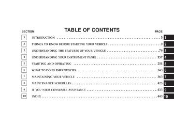
CONTENTS
m Instrument Panel And Controls . . . . . . . . . . . . . 161
m Base Instrument Cluster . . . . . . . . . . . . . . . . . . 162
m Premium Instrument Cluster — If Equipped . . . . 163
m Instrument Cluster Descriptions . . . . . . . . . . . . 164
m Electronic Vehicle Information Center (EVIC) –If Equipped . . . . . . . . . . . . . . . . . . . . . . . . . . . 175
N Electronic Vehicle Information Center (EVIC)Displays . . . . . . . . . . . . . . . . . . . . . . . . . . . . 177
N Oil Change Required . . . . . . . . . . . . . . . . . . . 178
N Trip Functions . . . . . . . . . . . . . . . . . . . . . . . 178N Compass Display . . . . . . . . . . . . . . . . . . . . . 181
N Telephone — If Equipped . . . . . . . . . . . . . . . 183
N Navigation — If Equipped . . . . . . . . . . . . . . . 185
N Personal Settings (Customer ProgrammableFeatures)
. . . . . . . . . . . . . . . . . . . . . . . . . . . 186
m Radio General Information . . . . . . . . . . . . . . . . 190
N Radio Broadcast Signals . . . . . . . . . . . . . . . . . 190
N Two Types Of Signals . . . . . . . . . . . . . . . . . . 190
N Electrical Disturbances . . . . . . . . . . . . . . . . . . 190158 UNDERSTANDING YOUR INSTRUMENT PANEL
N AM Reception . . . . . . . . . . . . . . . . . . . . . . . 190
N FM Reception . . . . . . . . . . . . . . . . . . . . . . . . 190m Sales Code REN — Multimedia System —
If Equipped . . . . . . . . . . . . . . . . . . . . . . . . . . . 191
N Operating Instructions — Satellite Radio(If Equipped)
. . . . . . . . . . . . . . . . . . . . . . . . 192
N Operating Instructions — Hands-Free
Communication (UConnect™) (If Equipped)
. . 192
N Clock Setting Procedure . . . . . . . . . . . . . . . . . 192m Sales Code REQ — AM/FM Stereo Radio And
6–Disc CD/DVD Changer (MP3/WMA AUX Jack) . . . . . . . . . . . . . . . . . . . . . . . . . . . . . . . . 194
N Operating Instructions - Radio Mode . . . . . . . 195
N Operation Instructions - (Disc Mode For CDAnd MP3/WMA Audio Play, DVD-Video) . . . . 203
N Notes On Playing MP3/WMA Files . . . . . . . . 205
N List Button (Disc Mode For MP3/WMAPlay)
. . . . . . . . . . . . . . . . . . . . . . . . . . . . . . 207
N Info Button (Disc Mode For MP3/WMA
Play)
. . . . . . . . . . . . . . . . . . . . . . . . . . . . . . 207
m Sales Code RER — Multimedia System —
If Equipped . . . . . . . . . . . . . . . . . . . . . . . . . . . 209
N Operating Instructions — Satellite Radio . . . . . 211
N Operating Instructions — Hands-FreeCommunication (UConnect™) (If Equipped)
. . 211
N Clock Setting Procedure . . . . . . . . . . . . . . . . . 211m Sales Code RES — AM/FM Stereo Radio With
CD Player (MP3 AUX Jack) . . . . . . . . . . . . . . . . 213
N Operating Instructions - Radio Mode . . . . . . . 214N Operation Instructions - CD Mode For CD
And MP3 Audio Play . . . . . . . . . . . . . . . . . . 219
N Notes On Playing MP3 Files . . . . . . . . . . . . . 222
N List Button (CD Mode For MP3 Play) . . . . . . . 224
N Info Button (CD Mode For MP3 Play) . . . . . . . 224m Satellite Radio (RSC) — If Equipped (REQ And
RES Radios Only) . . . . . . . . . . . . . . . . . . . . . . 226
N System Activation . . . . . . . . . . . . . . . . . . . . . 226
N Electronic Serial Number/Sirius IdentificationNumber (ENS/SID) . . . . . . . . . . . . . . . . . . . . 226
N Selecting Satellite Mode . . . . . . . . . . . . . . . . . 227
N Satellite Antenna . . . . . . . . . . . . . . . . . . . . . . 227
N Reception Quality . . . . . . . . . . . . . . . . . . . . . 227
N Operating Instructions - Satellite Mode . . . . . . 227UNDERSTANDING YOUR INSTRUMENT PANEL 159
N Operating Instructions - Hands Free Phone
(If Equipped)
. . . . . . . . . . . . . . . . . . . . . . . . 230
N Operating Instructions - Video Entertainment
System (VESt) (If Equipped)
. . . . . . . . . . . . . 230
m Video Entertainment System — If Equipped . . . . 230
m Universal Consumer Interface (UCI) —If Equipped . . . . . . . . . . . . . . . . . . . . . . . . . . . 232
N Connecting The iPodt . . . . . . . . . . . . . . . . . . 233
N Controlling The iPodt Using Radio Buttons . . . 233
N Play Mode . . . . . . . . . . . . . . . . . . . . . . . . . . 233
N List Or Browse Mode . . . . . . . . . . . . . . . . . . 235
m Remote Sound System Controls . . . . . . . . . . . . . 237
m CD/DVD Disc Maintenance . . . . . . . . . . . . . . . 238
m Radio Operation And Cellular Phones . . . . . . . . 239160 UNDERSTANDING YOUR INSTRUMENT PANEL
m Climate Controls . . . . . . . . . . . . . . . . . . . . . . . 239
N Manual Air Conditioning And Heating
System . . . . . . . . . . . . . . . . . . . . . . . . . . . . . 239
N Automatic Temperature Control —
If Equipped . . . . . . . . . . . . . . . . . . . . . . . . . 242
N Operating Tips . . . . . . . . . . . . . . . . . . . . . . . 247
m Rear Window Features . . . . . . . . . . . . . . . . . . . 250
N Electric Rear Window Defroster . . . . . . . . . . . 250INSTRUMENT PANEL AND CONTROLS
UNDERSTANDING YOUR INSTRUMENT PANEL 161
6 — Radio 7 — Climate Control 8 — Heated Seat Switch* 9 — Power Outlet
10 — Ash Tray*
11 — Ignition Switch 12 — Hood Release 13 — Trunk Release Switch 14 — Headlight Switch
* If Equipped
1 — Air Outlet 2 — Instrument Cluster 3 — Hazard Switch 4 — Electronic Stability Program Off Button*
/ Traction Control System Off Button*
5 — Glove Box
162 UNDERSTANDING YOUR INSTRUMENT PANEL
BASE INSTRUMENT CLUSTER
PREMIUM INSTRUMENT CLUSTER — IF EQUIPPED
UNDERSTANDING YOUR INSTRUMENT PANEL 163
164 UNDERSTANDING YOUR INSTRUMENT PANEL
INSTRUMENT CLUSTER DESCRIPTIONS
1. Fuel Gauge The pointer shows the level of fuel in the fuel tank when the ignition switch is in the ON position. 2. Trip Odometer Button
Base Cluster The word 9TRIP9 will appear when this button is pressed. Push in and hold the button for two seconds when the trip odometer displays to reset it to 0 miles (kilometers). A second press of the button will display the outside temperature in the odometer. Premium Cluster Press this button to change the display from odometer to either of two trip odometer settings. The letter “A” or “B” will appear when in the trip odometer mode. Push in and
hold the button for two seconds to reset the trip odometer to 0 miles (kilometers). The odometer must be in trip mode to reset it. 3. Speedometer Indicates vehicle speed. 4. Electronic Speed Control Indicator Light — If Equipped
This light will turn on when the electronic speed control is ON. (See page 135 for more information.)
5. Tachometer The red segments indicate the maximum permissible engine revolutions-per-minute (r.p.m. x 1000) for each gear range. Ease up on the accelerator before reaching the red area.
6. Charging System Light
This light shows the status of the electrical charg- ing system. The light should turn on when the ignition switch is first turned ON and remain on briefly as a bulb check. If the light stays on or turns on while driving, turn off some of the vehicle’s non-essential electrical devices (i.e. radio), or slightly increase engine speed (if at idle). If the light remains on, it means that the charging system is experiencing a problem. See your local authorized dealer to obtain SERVICE IMMEDI- ATELY. 7. Electronic Throttle Control (ETC) Light
This light will turn on briefly as a bulb check when the ignition switch is turned ON. This light will also turn on while the engine is running if there is a problem with the Elec- tronic Throttle Control system.
UNDERSTANDING YOUR INSTRUMENT PANEL 165
If the light comes on while the engine is running, safely bring the vehicle to a complete stop as soon as possible, place the gear selector in park, and cycle the ignition key. The light should turn off. If the light remains lit with the engine running, your vehicle will usually be drivable. However, see your dealer for service as soon as possible. If the light is flashing when the engine is running, immediate service is required. In this case, you may experience reduced performance, an elevated/rough idle or engine stall, and your vehicle may require towing. Also, have the system checked by an authorized dealer if the light does not come on during starting. 8. Temperature Gauge The temperature gauge shows engine coolant tempera- ture. Any reading within the normal range indicates that the engine cooling system is operating satisfactorily.
166 UNDERSTANDING YOUR INSTRUMENT PANEL
The gauge pointer will likely indicate a higher tempera- ture when driving in hot weather, up mountain grades, or when towing a trailer. It should not be allowed to exceed the upper limits of the normal operating range.
CAUTION!
Driving with a hot engine cooling system could damage your vehicle. If temperature gauge reads (H), pull over and stop the vehicle. Idle the vehicle with the air conditioner turned off until the pointer drops back into the normal range. If the pointer remains on the “H”, and you hear a chime, turn the engine off immediately, and call for service.
WARNING!
A hot engine cooling system is dangerous. You or others could be badly burned by steam or boiling coolant. You may want to call a service center if your vehicle overheats. If you decide to look under the hood yourself, see Section 7 of this manual. Follow the warnings under the Cooling System Pressure Cap paragraph.
9. Turn Signal Indicators
The arrow will flash with the exterior turn signal when the turn signal lever is operated.
NOTE: A continuous chime will sound if the vehicle is driven more than 1 mile (1.6 km) with either turn signal on.
NOTE: Check for a defective outside light bulb if either indicator flashes at a rapid rate. (See page 127 for more information.) 10. Airbag Warning Light
This light will turn on for 6 to 8 seconds as a bulb check when the ignition switch is first turned ON. If the light is either not on during starting, or stays on, or turns on while driving, then have the system inspected at your authorized dealer as soon as possible. (See page 62 for more information.) 11. Engine Temperature Warning Light
This light will turn on and a single chime will sound to warn of an overheated engine condition. When this light turns on, the engine temperature is critically hot. The vehicle should be turned off imme- diately and serviced as soon as possible. (See page 345 for more information.)
UNDERSTANDING YOUR INSTRUMENT PANEL 167
12. Electronic Stability Program (ESP)/Traction Control System (TCS) Indicator Light — If Equipped
If this indicator light flashes during accelera- tion, ease up on the accelerator and apply as little throttle as possible. Adapt your speed and driving to the prevailing road conditions, and do not switch off the ESP. (See page 284 for more information.) (See page 286 for more information.) 13. Electronic Stability Program (ESP) / Brake Assist System (BAS) Malfunction Indicator Light — If Equipped
The yellow ESP/BAS malfunction indicator light will turn on when the key in the ignition switch is turned to the “ON” position. The light should go out with the engine running. The system will turn this light on continuously while the engine running if it detects a malfunction in either the ESP or the BAS or both. (See page 286 for more informa- tion.)
168 UNDERSTANDING YOUR INSTRUMENT PANEL
14. Oil Pressure Warning Light
This light shows low engine oil pressure. The light should turn on momentarily when the engine is started. If the light turns on while driving, stop the vehicle, and shut off the engine as soon as possible. A single chime will sound when this light turns on. Do not operate the vehicle until the cause is corrected. This light does not show how much oil is in the engine. The engine oil level must be checked using the procedure shown in section 7. (See page 374 for more information.) 15. High Beam Light This light will turn on when the high beam headlights are ON. Push the Multi-Function lever away from the steering wheel to switch the headlights to high beam. (See page 126 for more information.)
16. Seat Belt Reminder Light
This light will turn on for 5 to 8 seconds as a bulb check when the ignition switch is first turned ON. A chime will sound if the driver’s seat belt is unbuckled during the bulb check. The Seat Belt Warning Light will flash or remain on continuously if the driver’s seat belt remains unbuckled after the bulb check or when driving. (See page 47 for more information.) 17. Transmission Range Indicator This display indicator shows the automatic transmission gear selection. 18. Front Fog Light Indicator — If Equipped
This light will turn on when the front fog lights are ON. (See page 126 for more information.)
19. Odometer/Trip Odometer The odometer shows the total distance the vehicle has been driven. The trip odometer shows individual trip mileage. Refer to “Trip Odometer Button” for additional information. NOTE: U.S. federal regulations require upon transfer of vehicle ownership, the seller certify the mileage the vehicle has been driven. Therefore, if the odometer reading is changed because of repair or replacement, be sure to keep a record of the reading before and after the service so that the correct mileage can be determined. On vehicles equipped with a Premium Instrument Clus- ter, this display shows the Electronic Vehicle Information Center (EVIC) messages when the appropriate conditions exist. (See page 175 for more information.)
UNDERSTANDING YOUR INSTRUMENT PANEL 169
Loose Fuel Filler Cap Message If the vehicle diagnostic system determines that the fuel filler cap is loose, improperly installed, or damaged, a “Check Gascap” message will display in the Electronic Vehicle Information Center (EVIC) — if equipped. Tighten the fuel filler cap properly and press the odom- eter reset button to turn off the message. If the problem continues, the message will appear the next time the vehicle is started. A loose, improperly installed, or damaged fuel filler cap may also turn on the Malfunction Indicator Light (MIL). (See page 370 for more information.) Change Oil Message (Base Cluster) Your vehicle is equipped with an engine oil change indicator system. The “Change Oil” message will flash in the instrument cluster odometer for approximately 12
seconds after a single chime has sounded to indicate the170 UNDERSTANDING YOUR INSTRUMENT PANEL
next scheduled oil change interval. The engine oil change indicator system is duty cycle based, which means the engine oil change interval may fluctuate dependent upon your personal driving style. Unless reset, this message will continue to display each time you turn the ignition switch to the “ON” position. To turn off the message temporarily, press and release the Trip Odometer button on the instrument cluster. To reset the oil change indicator system (after performing the scheduled maintenance) perform the following proce- dure:
1. Turn the ignition switch to the ON position (Do not start the engine). 2. Fully depress the accelerator pedal slowly three times within 10 seconds. 3. Turn the ignition switch to the LOCK position.
If the indicator message illuminates when you NOTE: start the vehicle, the oil change indicator system did not reset. If necessary, repeat this procedure. 20. Brake System Warning Light
This light monitors various brake functions, including brake fluid level and parking brake application. If the brake light turns on, it may indicate that the parking brake is applied, that the brake fluid level is low, or that there is a problem with the anti-lock brake system (if equipped). The dual brake system provides a reserve braking capac- ity to a portion of the hydraulic system in the event of a failure. Failure of either half of the dual brake system is indicated by the Brake Warning Light, which will turn on when the brake fluid level in the master cylinder drops below a specified level. The light will remain on until the cause is corrected.
NOTE: The light may flash momentarily during sharp cornering maneuvers, which change fluid level condi- tions. The vehicle should have service performed, and the brake fluid level checked. Immediate repair is necessary if brake failure is indicated.
WARNING!
Driving a vehicle with the brake light on is danger- ous. Part of the brake system may have failed. It will take longer to stop the vehicle. You could have an accident. Have the vehicle checked immediately.
Vehicles equipped with Anti-Lock brakes (ABS) are also equipped with Electronic Brake Force Distribution (EBD). Both the Brake Warning Light and the ABS Light will
UNDERSTANDING YOUR INSTRUMENT PANEL 171
turn on in the event of an EBD failure. Immediate repair of the ABS system is required in the event of an EBD failure. The operation of the Brake Warning Light can be checked by turning the ignition switch from the OFF position to the ON position. The light should turn on for approxi- mately two seconds and then turn off. The light will remain on if the parking brake is applied or if a brake fault is detected. If the parking brake is not applied and the light remains on, or if the light does not turn on, have the light inspected by an authorized dealer. NOTE: The light will turn on when the ignition switch in the ON position and the parking brake is applied. This light shows only that the parking brake is applied. It does not show the degree of brake application. (See page 280
for more information.)