- 2012 Dodge Challenger Owners Manuals
- Dodge Challenger Owners Manuals
- 2009 Dodge Challenger Owners Manuals
- Dodge Challenger Owners Manuals
- 2010 Dodge Challenger Owners Manuals
- Dodge Challenger Owners Manuals
- 2013 Dodge Challenger Owners Manuals
- Dodge Challenger Owners Manuals
- 2011 Dodge Challenger Owners Manuals
- Dodge Challenger Owners Manuals
- Download PDF Manual
-
Go™ in the ACC or ON/RUN mode. A child could operate power windows, other controls, or move the vehicle.
Manual Transmission – If Equipped Apply the parking brake, place the shift lever in NEUTRAL and press the clutch pedal before starting vehicle. This vehicle is equipped with a clutch interlocking ignition system. It will not start unless the clutch pedal is pressed to the floor.
Normal Starting With Integrated Key – Manual Transmission Normal starting of either a cold or a warm engine does not require pumping or pressing the accelerator pedal. Press the clutch pedal fully to the floor, and turn the ignition switch to the START position and release when the engine starts. If the engine fails to start within 15 seconds, turn the ignition switch to the OFF position, wait 10 to 15 seconds, then repeat the “Normal Starting” procedure.
STARTING AND OPERATING 301
WARNING!
Do not attempt to push or tow your vehicle to get it started. Unburned fuel could enter the catalytic con- verter and once the engine has started, ignite and damage the converter and vehicle. If the vehicle has a discharged battery, booster cables may be used to obtain a start from another vehicle. This type of start can be dangerous if done improperly, so follow the procedure carefully. Refer to “Jump Starting” in “What To Do In Emergencies” for further information.
302 STARTING AND OPERATING Automatic Transmission – If Equipped The shift lever must be in the NEUTRAL or PARK position before you can start the engine. Apply the brakes before shifting into any driving gear.
CAUTION!
Damage to the transmission may occur if the follow- ing precautions are not observed: • Do not shift from REVERSE, PARK, or NEUTRAL into any forward gear when the engine is above idle speed. • Shift into PARK only after the vehicle has come to a complete stop. • Shift into or out of REVERSE only after the vehicle has come to a complete stop and the engine is at idle speed. • Before shifting into any gear, make sure your foot is firmly on the brake pedal.
Using Fob With Integrated Key (Tip Start) NOTE: Normal starting of either a cold or a warm engine is obtained without pumping or pressing the accelerator pedal. Do not press the accelerator. Use the Fob with Integrated Key to briefly turn the ignition switch to the START position and release it as soon as the starter engages. The starter motor will continue to run, and it will disengage automatically when the engine is running. If the engine fails to start, the starter will disengage automatically in 10 seconds. If this occurs, turn the ignition switch to the LOCK position, wait 10 to 15 seconds, then repeat the “Normal Starting” procedure.
Keyless Enter-N-Go™ – If Equipped
This feature allows the driver to oper- ate the ignition switch with the push of a button, as long as the ENGINE START/STOP button is installed and the Remote Start/Keyless Enter-N- Go™ FOBIK is in the passenger com- partment.
Installing And Removing The ENGINE START/STOP Button Installing The Button 1. Remove the key fob from the ignition switch. 2. Insert the ENGINE START/STOP button into the igni- tion switch with the lettering facing up and readable. 3. Press firmly on the center of the button to secure it into
position.
STARTING AND OPERATING 303
Removing The Button 1. The ENGINE START/STOP button can be removed
from the ignition switch for key fob use.
2. Insert the metal part of the emergency key under the chrome bezel at the 6 o’clock position and gently pry the button loose.
NOTE: The ENGINE START/STOP button should only be removed or inserted with the ignition in the OFF position (OFF position for Keyless Enter-N-Go™). Normal Starting
Using The ENGINE START/STOP Button – Automatic Transmission Only 1. The transmission must be in PARK or NEUTRAL. 2. Press and hold the brake pedal while pressing the
ENGINE START/STOP button once.
304 STARTING AND OPERATING 3. The system takes over and attempts to start the vehicle. If the vehicle fails to start, the starter will disengage automatically after 10 seconds.
4. If you wish to stop the cranking of the engine prior to
the engine starting, press the button again.
NOTE: Normal starting of either a cold or a warm engine is obtained without pumping or pressing the accelerator pedal. Using The ENGINE START/STOP Button – Manual Transmission Only 1. Press and hold the clutch pedal while pressing and
holding the ENGINE START/STOP button.
2. Release the button when the engine starts. If the vehicle fails to start within 15 seconds, release the button, wait 10 to 15 seconds, then repeat the “Normal Starting” procedure.
3. If you wish to stop the cranking of the engine prior to
the engine starting, release the button.
NOTE: Normal starting of either a cold or a warm engine is obtained without pumping or pressing the accelerator pedal. To Turn Off The Engine Using ENGINE START/STOP Button – Automatic Transmission Only 1. Place the shift lever in PARK, then press and release
the ENGINE START/STOP button.
2. The ignition switch will return to the OFF position. 3. If the shift lever is not in PARK, the ENGINE START/ STOP button must be held for two seconds and vehicle speed must be above 5 mph (8 km/h) before the engine will shut off. The ignition switch position will remain in the ACC position until the shift lever is in PARK and the button is pressed twice to the OFF position. If the shift lever is not in PARK and the
ENGINE START/STOP button is pressed once, the EVIC (if equipped) will display a “VEHICLE NOT IN PARK” message and the engine will remain running. Never leave a vehicle out of the PARK position, or it could roll.
NOTE: If the ignition switch is left in the ACC or RUN (engine not running) position and the transmission is in PARK, the system will automatically time out after 30 minutes of inactivity and the ignition will switch to the OFF position. To Turn Off The Engine Using ENGINE START/STOP Button – Manual Transmission Only 1. With the vehicle stopped, place the shift lever in then press and release the ENGINE
NEUTRAL, START/STOP button.
2. The ignition switch will return to the OFF position.
STARTING AND OPERATING 305
3. Place the shift lever in first gear or Reverse and thenapply the parking brake.
NOTE: • If the ignition switch is left in the ACC position, the system will automatically time out after 30 minutes of inactivity and the ignition will switch to the OFF position. • If the ignition switch is left in the RUN position, the system will automatically time out after 30 minutes of inactivity if the vehicle speed is 0 mph (0 km/h) and the engine is not running. • If the vehicle speed is above 5 mph (8 km/h), the ENGINE START/STOP button must be held for two seconds before the engine will shut off. The ignition switch position will remain in the ACC posi- tion until the vehicle is stopped and the button is pressed twice to the OFF position.
306 STARTING AND OPERATING Keyless Enter-N-Go™ Functions – With Driver’s Foot OFF The Brake Pedal/Clutch Pedal (In PARK Or NEUTRAL Position) The Keyless Enter-N-Go™ feature operates similar to an ignition switch. It has four positions, OFF, ACC, RUN and START. To change the ignition switch positions without starting the vehicle and use the accessories follow these steps. • Starting with the ignition switch in the OFF position: • Press the ENGINE START/STOP button once to change the ignition switch to the ACC position (EVIC displays “IGNITION MODE ACCESSORY”), • Press the ENGINE START/STOP button a second time to change the ignition switch to the RUN position (EVIC displays “IGNITION MODE RUN”), • Press the ENGINE START/STOP button a third time to return the ignition switch to the OFF position (EVIC displays “IGNITION MODE OFF”).
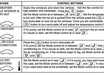
Extreme Cold Weather (Below –20°F Or −29°C) To ensure reliable starting at these temperatures, use of an externally powered electric engine block heater (avail- able from your authorized dealer) is recommended. If Engine Fails To Start
WARNING!
• Never pour fuel or other flammable liquids into the throttle body air inlet opening in an attempt to start the vehicle. This could result in a flash fire causing serious personal injury. • Do not attempt to push or tow your vehicle to get it started. Vehicles equipped with an automatic transmis- sion cannot be started this way. Unburned fuel could enter the catalytic converter and once the engine has started, ignite and damage the converter and vehicle.
(Continued)
WARNING! (Continued)
• If the vehicle has a discharged battery, booster cables may be used to obtain a start from a booster battery or the battery in another vehicle. This type of start can be dangerous if done improperly. Refer to “Jump Starting” in “What To Do In Emergen- cies” for further information.
Clearing A Flooded Engine (Using ENGINE START/STOP Button) – Automatic Transmission Only If the engine fails to start after you have followed the “Normal Starting” or “Extreme Cold Weather⬙ proce- dures, it may be flooded. To clear any excess fuel, press and hold the brake pedal, push the accelerator pedal all the way to the floor and hold it, then press and release the ENGINE START/STOP button once. The starter motor
STARTING AND OPERATING 307
will engage automatically, run for 10 seconds, and then disengage. Once this occurs, release the accelerator pedal and the brake pedal, wait 10 to 15 seconds, then repeat the “Normal Starting” procedure. Clearing A Flooded Engine (Using ENGINE START/STOP Button) – Manual Transmission Only If the engine fails to start after you have followed the “Normal Starting” or “Extreme Cold Weather⬙ proce- dures, it may be flooded. To clear any excess fuel, press and hold the clutch pedal, push the accelerator pedal all the way to the floor and hold it, then press and hold the ENGINE START/STOP button for no more than 15 sec- onds. Release the accelerator pedal and the clutch pedal, wait 10 to 15 seconds, then repeat the “Normal Starting” procedure.308 STARTING AND OPERATING Clearing A Flooded Engine (Using Fob With Integrated Key) If the engine fails to start after you have followed the “Normal Starting” or “Extreme Cold Weather” proce- dures, it may be flooded. To clear any excess fuel: 1. Press the accelerator pedal all the way to the floor and
hold it.
2. Turn the ignition switch to the START position and
release it as soon as the starter engages.
The starter motor will disengage automatically in 10 sec- onds. Once this occurs, release the accelerator pedal, turn the ignition switch to the LOCK position, wait 10 to 15 seconds, then repeat the “Normal Starting” procedure.
CAUTION!
To prevent damage to the starter, wait 10 to 15 sec- onds before trying again.
After Starting The idle speed is controlled automatically and it will decrease as the engine warms up.
ENGINE BLOCK HEATER — IF EQUIPPED The engine block heater warms the engine, and permits quicker starts in cold weather. Connect the cord to a standard 110-115 Volt AC electrical outlet with a grounded, three-wire extension cord. The engine block heater must be plugged in at least one hour to have an adequate warming effect on the engine. The engine block heater cord is routed under the hood on the driver side of the vehicle. It has a removable cap that is located on the driver side of the Integrated Power Module.
WARNING!
Remember to disconnect the engine block heater cord before driving. Damage to the 110-115 Volt electrical cord could cause electrocution.
MANUAL TRANSMISSION — IF EQUIPPED
Six-Speed Manual Transmission
WARNING!
You or others could be injured if you leave the vehicle unattended without having the parking brake fully applied. The parking brake should al- ways be applied when the driver is not in the vehicle, especially on an incline.
STARTING AND OPERATING 309
CAUTION!
• Never drive with your foot resting on the clutch pedal, or try to hold the vehicle on a hill with the clutch pedal partially engaged, as this will cause abnormal wear on the clutch. Refer to “Electronic Brake Control System/Hill Start Assist” in “Start- ing And Operating” for further information. • Failure to press the clutch pedal fully to the floor may cause increased shift efforts, and may result in damage to the clutch and transmission. • Do not rest your hand on the shift lever while driving, as this may result in transmission synchro- nizer damage. • Do not attempt to shift the transmission if the rear wheels are spinning due to loss of traction. Dam- age to the transmission may occur.
310 STARTING AND OPERATING NOTE: During cold weather, you may experience in- creased effort in shifting until the transmission fluid warms up. This is normal.
Manual Shifter
Shifting Fully press the clutch pedal and lift your foot off the accelerator pedal before shifting gears. As you release the clutch pedal, lightly press the accelerator pedal. Damage to the transmission or clutch may occur if you do not fully press the clutch pedal and lift off of the accelerator pedal when shifting. The six-speed manual transmission has a spring that centers the shift lever near third and fourth gear. This spring helps you know which gear you are in when you are shifting. Be careful when shifting from first to second or downshifting from sixth to fifth. The spring will try to pull the shift lever toward third and fourth gear. Make sure you move the shift lever into second or fifth gear. If you let the shift lever move in the direction of the pulling, you may end shifting from first to fourth or from sixth to third gear.
CAUTION!
Always make sure the vehicle comes to a complete stop before shifting into REVERSE. Failure to do so may result in transmission damage.
You must always use first gear (or Reverse) when starting from a standing position. Recommended Shift Speeds To utilize your manual transmission efficiently for fuel economy, it should be upshifted as listed in recom- mended shift speed chart.
STARTING AND OPERATING 311
MANUAL TRANSMISSION RECOMMENDED
SHIFT SPEEDS
Axle Ratio 3.73
3.91
1-4
20
(32) 20
(32)4-5
25
(40) 37
(59)5-6
42
(67) 48
(77)mph (km/h) mph (km/h)
Earlier upshifts during cruise conditions (relatively steady speeds) may result in increased fuel economy. Higher upshift speeds may be used to obtain a desired acceleration rate.
312 STARTING AND OPERATING NOTE: • Your vehicle is equipped with a transmission reverse inhibitor system. When vehicle speed is greater than 3 mph (5 km/h), the reverse inhibitor activates to help prevent shifts into REVERSE. When at a complete stop, you may notice lighter shift efforts into REVERSE with the ignition switch in the ON position (RUN position for Keyless Enter-N-Go), as compared to the ignition LOCK position (OFF position for Keyless Enter-N-Go). This is normal operation of the transmission reverse inhibitor system. • Due to the high performance nature of your drivetrain, you may hear your transmission. This can be most noticeable when the vehicle is idling in NEUTRAL with the clutch engaged (clutch pedal released), but it may also be heard when driving at low engine RPM. Also, this may be more noticeable when the transmission is warm. This is a normal condition and is not an indica- tion of a problem with your clutch or transmission.
1–4 Skip Shift There are times when you must shift the transmission directly from first gear to fourth gear instead of from first gear to second gear. This is to help you get the best possible fuel economy from your vehicle. This occurs when the engine coolant (antifreeze) is higher than 106°F (41°C), vehicle speed is greater than 19 mph (30 km/h) but less than 21 mph (34 km/h), and the transmission is in first gear, and the accelerator is at 1/4 throttle or less. The “1–4 Skip Shift Indicator Message” will be displayed during these times. When the “1–4 Skip Shift Indicator Message” is dis- played, the shift mechanism will only allow shifts from first gear to fourth gear. After you shift the transmission to fourth gear, you can press the clutch in and shift to another forward gear.
Downshifting To maintain a safe speed and prolong brake life, down- shift to maintain a safe speed when descending a steep grade.
WARNING!
Skipping more than one gear while downshifting, could cause you to lose control of your vehicle. You could have a collision.
CAUTION!
• If you skip more than one gear while downshifting or downshift at too high an engine speed, you could damage the engine, transmission, or clutch. • Do not downshift into first gear when the vehicle is moving faster than 15 mph (24 km/h), as you could damage the engine and/or clutch.
AUTOMATIC TRANSMISSION — IF EQUIPPED
STARTING AND OPERATING 313
CAUTION!
Damage to the transmission may occur if the follow- ing precautions are not observed: • Shift into PARK only after the vehicle has come to a complete stop. • Shift into or out of REVERSE only after the vehicle has come to a complete stop and the engine is at idle speed. • Do not shift between PARK, REVERSE, NEU- TRAL, or DRIVE when the engine is above idle speed. • Before shifting into any gear, make sure your foot is firmly pressing the brake pedal.
NOTE: You must press and hold the brake pedal while shifting out of PARK.
314 STARTING AND OPERATING
WARNING!
• Unintended movement of a vehicle could injure those in or near the vehicle. As with all vehicles, you should never exit a vehicle while the engine is running. Before exiting a vehicle, always apply the parking brake, shift the transmission into PARK, and turn the engine OFF. When the ignition is in the LOCK/OFF position, the shift lever is locked in PARK, securing the vehicle against unwanted movement. • It is dangerous to shift out of PARK or NEUTRAL if the engine speed is higher than idle speed. If your foot is not firmly pressing the brake pedal, the vehicle could accelerate quickly forward or in re- verse. You could lose control of the vehicle and hit someone or something. Only shift into gear when the engine is idling normally and your foot is firmly pressing the brake pedal.
(Continued)
WARNING! (Continued)
• When leaving the vehicle, always remove the key fob and lock your vehicle. • Never leave children alone in a vehicle, or with access to an unlocked vehicle. Allowing children to be in a vehicle unattended is dangerous for a number of reasons. A child or others could be seriously or fatally injured. • Children should be warned not to touch the park- ing brake, brake pedal or the shift lever. Do not leave the key fob in or near the vehicle (or in a location accessible to children), and do not leave Keyless Enter-N-Go™ in the ACC or ON/RUN position. A child could operate power windows, other controls, or move the vehicle.
Key Ignition Park Interlock This vehicle is equipped with a Key Ignition Park Inter- lock which requires the shift lever to be placed in PARK before the engine can be turned off. This helps the driver avoid inadvertently leaving the vehicle without placing the transmission in PARK. This system also locks the shift lever in PARK whenever the ignition switch is in the OFF position. Brake/Transmission Shift Interlock System This vehicle is equipped with a Brake Transmission Shift Interlock system (BTSI) that holds the shift lever in PARK unless the brakes are applied. To move the shift lever out of PARK, the ignition switch must be turned to the ON/RUN position (engine running or not) and the brake pedal must be pressed.
STARTING AND OPERATING 315
Five-Speed Automatic Transmission The shift lever position display (located in the instrument cluster) indicates the transmission gear range. You must press the brake pedal to move the shift lever out of PARK (refer to “Brake/Transmission Shift Interlock System” in this section). To drive, move the shift lever from PARK or NEUTRAL to the DRIVE position. The electronically-controlled transmission provides a precise shift schedule. The transmission electronics are self-calibrating; therefore, the first few shifts on a new vehicle may be somewhat abrupt. This is a normal condition, and precision shifts will develop within a few hundred miles (kilometers).
316 STARTING AND OPERATING Only shift from DRIVE to PARK or REVERSE when the accelerator pedal is released and the vehicle is stopped. Be sure to keep your foot on the brake pedal when moving the shift lever between these gears. The transmission shift lever has only PARK, REVERSE, NEUTRAL, and DRIVE shift positions. Manual down- shifts can be made using the “AutoStick威” shift control (refer to “AutoStick威” in this section). Moving the shift lever to the left or right (-/+) while in the DRIVE position, or tapping one of the steering wheel-mounted shift paddles (-/+), will manually select the transmission gear, and will display that gear in the instrument cluster as 5, 4, 3, 2, 1.
Shift Lever
Gear Ranges DO NOT race the engine when shifting from PARK or NEUTRAL into another gear range. If there is a need to restart the engine, be sure to cycle the ignition to the LOCK/OFF position before restarting.
Transmission gear engagement may be delayed after restarting the engine if the key is not cycled to the LOCK/OFF position first. NOTE: After selecting any gear range, wait a moment to allow the selected gear to engage before accelerating. This is especially important when the engine is cold. PARK This range supplements the parking brake by locking the transmission. The engine can be started in this range. Never attempt to use PARK while the vehicle is in motion. Apply the parking brake when leaving the vehicle in this range. When parking on a level surface, you may place the shift lever in PARK first, and then apply the parking brake. When parking on a hill, apply the parking brake before placing the shift lever in PARK, otherwise the load on the
STARTING AND OPERATING 317
transmission locking mechanism may make it difficult to move the shift lever out of PARK. As an added precau- tion, turn the front wheels toward the curb on a downhill grade and away from the curb on an uphill grade.WARNING!
• Never use the PARK position as a substitute for the parking brake. Always apply the parking brake fully when parked to guard against vehicle move- ment and possible injury or damage. • Your vehicle could move and injure you and others if it is not completely in PARK. Check by trying to move the shift lever rearward (with the brake pedal released), after you have placed it in PARK. Make sure the transmission is in PARK before leaving the vehicle.
(Continued)
318 STARTING AND OPERATING
WARNING! (Continued)
• It is dangerous to move the shift lever out of PARK or NEUTRAL if the engine speed is higher than idle speed. If your foot is not firmly pressing the brake pedal, the vehicle could accelerate quickly forward or in reverse. You could lose control of the vehicle and hit someone or something. Only shift into gear when the engine is idling normally and your foot is firmly pressing the brake pedal. • Unintended movement of a vehicle could injure those in or near the vehicle. As with all vehicles, you should never exit a vehicle while the engine is running. Before exiting a vehicle, always apply the parking brake, shift the transmission into PARK, turn the engine OFF, and remove the key fob. When the ignition is in the OFF position, the shift lever is
(Continued)
WARNING! (Continued)
locked in PARK, securing the vehicle against un- wanted movement. • When leaving the vehicle, always remove the key fob and lock your vehicle. • Never leave children alone in a vehicle, or with access to an unlocked vehicle. Allowing children to be in a vehicle unattended is dangerous for a number of reasons. A child or others could be seriously or fatally injured. Children should be warned not to touch the parking brake, brake pedal or the shift lever. • Do not leave the key fob in or near the vehicle (or in a location accessible to children), and do not leave Keyless Enter-N-Go™ in the ACC or ON/ RUN position. A child could operate power win- dows, other controls, or move the vehicle.
CAUTION!
• Before moving the shift lever out of PARK, you must turn the ignition switch from the OFF posi- tion to the ON/RUN position, and also press the brake pedal. Otherwise, damage to the shift lever could result. • DO NOT race the engine when shifting from PARK or NEUTRAL into another gear range, as this can damage the drivetrain.
The following indicators should be used to ensure that you have engaged the shift lever into the PARK position: • When shifting into PARK, firmly move the shift lever all the way forward and to the left until it stops and is fully seated.
STARTING AND OPERATING 319
• Look at the shift lever position display and verify that • With brake pedal released, verify that the shift lever
it indicates the PARK position.
will not move out of PARK.
REVERSE This range is for moving the vehicle backward. Shift into REVERSE only after the vehicle has come to a complete stop. NEUTRAL Use this range when the vehicle is standing for prolonged periods with the engine running. The engine may be started in this range. Apply the parking brake and shift the transmission into PARK if you must leave the vehicle.
320 STARTING AND OPERATING
WARNING!
Do not coast in NEUTRAL and never turn off the ignition to coast down a hill. These are unsafe practices that limit your response to changing traffic or road conditions. You might lose control of the vehicle and have a collision.
CAUTION!
Towing the vehicle, coasting, or driving for any other reason with the transmission in NEUTRAL can cause severe transmission damage. Refer to “Recreational Towing” in “Starting And Operating” and “Towing A Disabled Vehicle” in “What To Do In Emergencies” for further information.
DRIVE This range should be used for most city and highway driving. It provides the smoothest upshifts and down- shifts, and the best fuel economy. The transmission automatically upshifts through underdrive first, second, and third gears, direct fourth gear and overdrive fifth gear. The DRIVE position provides optimum driving characteristics under all normal operating conditions. When frequent transmission shifting occurs (such as when operating the vehicle under heavy loading condi- tions, in hilly terrain, traveling into strong head winds, or while towing heavy trailers), use the “AutoStick威” shift control (refer to “AutoStick威” in this section) to select a lower gear. Under these conditions, using a lower gear will improve performance and extend transmission life by reducing excessive shifting and heat buildup.
Transmission Limp Home Mode Transmission function is monitored electronically for abnormal conditions. If a condition is detected that could result in transmission damage, Transmission Limp Home Mode is activated. In this mode, the transmission remains in the current gear until the vehicle is brought to a stop. After the vehicle has stopped, the transmission will remain in second gear regardless of which forward gear is selected. PARK, REVERSE, and NEUTRAL will con- tinue to operate. Limp Home Mode allows the vehicle to be driven to an authorized dealer for service without damaging the transmission. In the event of a momentary problem, the transmission can be reset to regain all forward gears by performing the following steps: 1. Stop the vehicle. 2. Shift the transmission into PARK.
STARTING AND OPERATING 321
3. Turn the engine OFF. 4. Wait approximately 10 seconds. 5. Restart the engine. 6. Shift into the desired gear range. If the problem is no longer detected, the transmission will return to normal operation.
NOTE: Even if the transmission can be reset, we recom- mend that you visit your authorized dealer at your earliest possible convenience. Your authorized dealer has diagnostic equipment to determine if the problem could recur. If the transmission cannot be reset, authorized dealer service is required.
322 STARTING AND OPERATING Overdrive Operation The automatic transmission includes an electronically controlled Overdrive (fifth gear). The transmission will automatically shift into Overdrive if the following con- ditions are present: • the shift lever is in the DRIVE position, • vehicle speed is sufficiently high, and • the driver is not heavily pressing the accelerator. AUTOSTICK姞 AutoStick威 is a driver-interactive transmission feature providing manual shift control, giving you more control of the vehicle. AutoStick威 allows you to maximize engine braking, eliminate undesirable upshifts and downshifts, and improve overall vehicle performance. This system can also provide you with more control during passing, city driving, cold slippery conditions, mountain driving, trailer towing, and many other situations.
Operation When the shift lever is in the DRIVE position, the trans- mission will operate automatically, shifting between the five available gears. To engage AutoStick威, simply move the shift lever to the right or left (+/-) while in the DRIVE position, or tap one of the steering wheel-mounted shift paddles (+/-), if equipped. Tapping (-) to enter AutoStick威 mode will downshift the transmission to the next lower gear, while using (+) to enter AutoStick威 mode will retain the current gear. When AutoStick威 is active, the current transmission gear is displayed in the instrument cluster. In AutoStick威 mode, the transmission will shift up or down when (+/-) is manually selected by the driver (using the shift lever, or the shift paddles [if equipped]), unless an engine lugging or overspeed condition would result.
It will remain in the selected gear until another upshift or downshift is chosen, except as described below. • If AutoStick威 is engaged while in DRIVE mode, the transmission will automatically shift up when maxi- mum engine speed is reached. • If AutoStick威 is engaged while in SPORT mode, the transmission will remain in the selected gear even when maximum engine speed is reached. The trans- mission will upshift only when commanded by the driver. Engine overspeed protection will be provided by fuel cut off at or near redline. • The transmission will automatically downshift as the vehicle slows (to prevent engine lugging) and will display the current gear. • The transmission will automatically downshift to first gear when coming to a stop. After a stop, the driver should manually upshift (+) the transmission as the vehicle is accelerated.
STARTING AND OPERATING 323
• You can start out, from a stop, in first or second gear. Tapping (+) (at a stop) will allow starting in second gear. Starting out in second gear is helpful in snowy or icy conditions. • The system will ignore attempts to upshift at too low • Avoid using speed control when AutoStick威 is • Transmission shifting will be more noticeable when
of a vehicle speed.
engaged.
AutoStick威 is engaged.
To disengage AutoStick威 mode, hold the shift lever to the right or press and hold the (+) shift paddle (if equipped) until “D” is once again displayed in the instrument cluster. You can shift in or out of the AutoStick威 mode at any time without taking your foot off the accelerator pedal.
On the center console, there is a “SPORT” button that when pressed will cycle through three different driving modes. This is the description of each mode of operation:
324 STARTING AND OPERATING
WARNING!
Do not downshift for additional engine braking on a slippery surface. The drive wheels could lose their grip and the vehicle could skid, causing a collision or personal injury.
SPORT MODE — IF EQUIPPED This vehicle is equipped with an electronic controlled dampening system. This system reduces body roll and pitch in many driving situations including cornering, acceleration and braking. In addition, the driver has the ability to select a more aggressive shifting pattern.
SPORT Button
• Off – This is the initial position. This mode will give a sporty, but comfortable ride. Within this mode, the suspension will adapt to the vehicle inputs, including vehicle speed, steering inputs, braking and accelera- tion. The transmission will be optimized for smooth, less aggressive shifting. The system will return to OFF when the ignition switch is cycled from RUN to OFF to RUN, if this mode is selected. • Sport Mode – This mode is selected by the first press of the “SPORT” button. A “SPORT” message will display in the instrument cluster. The system will return to SPORT mode when the ignition switch is cycled from RUN to OFF to RUN, if this mode is selected. This mode will set suspension for maximum performance handling and is intended for spirited driving.
STARTING AND OPERATING 325
• TRACK Mode – This includes SPORT mode and affects automatic transmission shifting in either Auto or Manual mode. Refer to “AutoStick” in “Starting And Operating” for further information. In TRACK mode, the transmission has a sportier, more aggressive shift pattern. In Manual mode, the transmission will hold gear at redline during manual shifting (console shifter or paddle shifters). A “TRACK” message will display in the instrument cluster. The system will return to SPORT mode when the ignition switch is cycled from RUN to OFF to RUN, if this mode is selected.
NOTE: For manual transmission vehicles, the available driving modes are Sport on or Sport Off. Track is not available.
326 STARTING AND OPERATING DRIVING ON SLIPPERY SURFACES
Acceleration Rapid acceleration on snow covered, wet, or other slip- pery surfaces may cause the driving wheels to pull erratically to the right or left. This phenomenon occurs when there is a difference in the surface traction under the rear (driving) wheels.
WARNING!
Rapid acceleration on slippery surfaces is dangerous. Unequal traction can cause sudden pulling of the rear wheels. You could lose control of the vehicle and possibly have a collision. Accelerate slowly and carefully whenever there is likely to be poor traction (ice, snow, wet mud, loose sand, etc.).
Traction When driving on wet or slushy roads, it is possible for a wedge of water to build up between the tire and road surface. This is known as hydroplaning and may cause partial or complete loss of vehicle control and stopping ability. To reduce this possibility, the following precau- tions should be observed: 1. Slow down during rainstorms or when the roads are
slushy.
2. Slow down if the road has standing water or puddles. 3. Replace tires when tread wear indicators first become
visible.
4. Keep tires properly inflated. 5. Maintain sufficient distance between your vehicle and the vehicle in front of you to avoid a collision in a sudden stop.
Your vehicle is equipped with a Limited Slip Differential (LSD) that reduces, but does not eliminate, the amount of wheel slip across a given axle for improved handling. DRIVING THROUGH WATER Driving through water more than a few inches/ centimeters deep will require extra caution to ensure safety and prevent damage to your vehicle. Flowing/Rising Water
WARNING!
Do not drive on, or cross, a road or a path where water is flowing and/or rising (as in storm run-off). Flowing water can wear away the road or path’s surface and cause your vehicle to sink into deeper water. Furthermore, flowing and/or rising water can carry your vehicle away swiftly. Failure to follow this warning may result in injuries that are serious or fatal to you, your passengers, and others around you.
STARTING AND OPERATING 327
Shallow Standing Water Although your vehicle is capable of driving through shallow standing water, consider the following Caution and Warning before doing so.
CAUTION!
• Always check the depth of the standing water before driving through it. Never drive through standing water that is deeper than the bottom of the tire rims mounted on the vehicle. • Determine the condition of the road or the path that is under water and if there are any obstacles in the way before driving through the standing water. • Do not exceed 5 mph (8 km/h) when driving through standing water. This will minimize wave effects.
(Continued)
328 STARTING AND OPERATING
CAUTION! (Continued)
• Driving through standing water may cause damage to your vehicle’s drivetrain components. Always inspect your vehicle’s fluids (i.e., engine oil, trans- mission, axle, etc.) for signs of contamination (i.e., fluid that is milky or foamy in appearance) after driving through standing water. Do not con- tinue to operate the vehicle if any fluid appears contaminated, as this may result in further damage. Such damage is not covered by the New Vehicle Limited Warranty. • Getting water inside your vehicle’s engine can cause it to lock up and stall out, and cause serious internal damage to the engine. Such damage is not covered by the New Vehicle Limited Warranty.
WARNING!
• Driving through standing water limits your vehi- cle’s traction capabilities. Do not exceed 5 mph (8 km/h) when driving through standing water. • Driving through standing water limits your vehi- cle’s braking capabilities, which increases stopping distances. Therefore, after driving through stand- ing water, drive slowly and lightly press on the brake pedal several times to dry the brakes. • Getting water inside your vehicle’s engine can cause it to lock up and stall out, and leave you stranded. • Failure to follow these warnings may result in injuries that are serious or fatal to you, your pas- sengers, and others around you.
POWER STEERING Your vehicle is equipped with an electro-hydraulic power steering system that will give you good vehicle response and increased ease of maneuverability in tight spaces. The system will vary its assist to provide light efforts while parking and good feel while driving. If the electro- hydraulic power steering system experiences a fault that prevents it from providing power steering assist, then the system will provide mechanical steering capability.
CAUTION!
Extreme steering maneuvers may cause the electri- cally driven pump to reduce or stop power steering assistance in order to prevent damage to the system. Normal operation will resume once the system is allowed to cool.
STARTING AND OPERATING 329
If the “SERVICE POWER STEERING SYSTEM” message and a flashing icon are displayed on the EVIC screen, it indicates that the vehicle needs to be taken to the dealer for service. It is likely the vehicle has lost power steering assistance. Refer to “Electronic Vehicle Information (EVIC)” in “Under- standing Your Instrument Panel” for further information. If the “POWER STEERING SYSTEM OVER TEMP” mes- sage and an icon are displayed on the EVIC screen, it indicates that extreme steering maneuvers may have occurred, which caused an over temperature condition in the power steering system. You will lose power steering assistance momentarily until the over temperature con- dition no longer exists. Once driving conditions are safe, then pull over and let vehicle idle for a few moments until the light turns off. Refer to “Electronic Vehicle Information (EVIC)” in “Understanding Your Instrument Panel” for further information.330 STARTING AND OPERATING NOTE: • Even if power steering assistance is no longer opera- tional, it is still possible to steer the vehicle. Under these conditions there will be a substantial increase in steering effort, especially at very low vehicle speeds and during parking maneuvers. • If the condition persists, see your authorized dealer for
service.
FUEL SAVER TECHNOLOGY (IF EQUIPPED) — 5.7L ENGINE ONLY This feature offers improved fuel economy by shutting off four of the engine’s eight cylinders during light load and cruise conditions. The system is automatic with no driver inputs or additional driving skills required. NOTE: This system may take some time to return to full functionality after a battery disconnect.
PARKING BRAKE Before leaving the vehicle, make sure that the parking brake is fully applied and place the shift lever in the PARK or REVERSE (manual transmission only) position. When the parking brake is applied and the ignition switch is in the ON position (RUN position with Keyless Enter-N-Go™), the “Brake Warning Light” in the instru- ment cluster will illuminate. NOTE: • When the parking brake is applied and the transmis- sion is placed in gear, the “Brake Warning Light” will flash. If vehicle speed is detected, a chime will sound to alert the driver. Fully release the parking brake before attempting to move the vehicle. • This light only shows that the parking brake is applied.
It does not show the degree of brake application.
When parking on a hill, it is important to turn the front wheels toward the curb on a downhill grade and away from the curb on an uphill grade. For vehicles equipped with an automatic transmission, apply the parking brake before placing the shift lever in PARK, otherwise the load on the transmission locking mechanism may make it difficult to move the shift lever out of PARK. The parking brake should always be applied whenever the driver is not in the vehicle. Manual Transmission – If Equipped The foot operated parking brake is positioned below the lower left corner of the instrument panel. To release the parking brake, pull the parking brake release handle.
STARTING AND OPERATING 331
Parking Brake Release
332 STARTING AND OPERATING Automatic Transmission – If Equipped The foot operated parking brake is located below the lower left corner of the instrument panel. To apply the park brake, firmly push the park brake pedal fully. To release the parking brake, press the park brake pedal a second time and let your foot up as you feel the brake disengage.
Parking Brake
WARNING!
• Never use the PARK position as a substitute for the parking brake. Always apply the parking brake fully when parked to guard against vehicle move- ment and possible injury or damage. • When leaving the vehicle, always remove the key fob from the ignition and lock your vehicle. • Never leave children alone in a vehicle, or with access to an unlocked vehicle. Allowing children to be in a vehicle unattended is dangerous for a number of reasons. A child or others could be seriously or fatally injured. Children should be warned not to touch the parking brake, brake pedal or the shift lever.
(Continued)
WARNING! (Continued)
• Do not leave the key fob in or near the vehicle (or in a location accessible to children), and do not leave a vehicle equipped with Keyless Enter-N- Go™ in the ACC or ON/RUN mode. A child could operate power windows, other controls, or move the vehicle. • Be sure the parking brake is fully disengaged before driving; failure to do so can lead to brake failure and a collision. • Always fully apply the parking brake when leav- ing your vehicle, or it may roll and cause damage or injury. Also be certain to leave the transmission in PARK. Failure to do so may allow the vehicle to roll and cause damage or injury.
STARTING AND OPERATING 333
CAUTION!
If the “Brake Warning Light” remains on with the parking brake released, a brake system malfunction is indicated. Have the brake system serviced by an authorized dealer immediately.
BRAKE SYSTEM
Your vehicle is equipped with dual hydraulic brake systems. If either of the two hydraulic systems loses normal capability, the remaining system will still function. There will be some loss of overall braking effectiveness. This may be evident by increased pedal travel during application, greater pedal force required to slow or stop, and potential activation of the “Brake Warning Light.”
334 STARTING AND OPERATING In the event power assist is lost for any reason (for example, repeated brake applications with the engine OFF) the brakes will still function. The effort required to brake the vehicle will be much greater than that required with the power system operating. Anti-Lock Brake System (ABS) The Anti-Lock Brake System (ABS) provides increased vehicle stability and brake performance under most braking conditions. The system automatically “pumps” the brakes during severe braking conditions to prevent wheel lock-up. The Electronic Brake Force Distribution (EBD) prevents the rear wheels from over-braking and provides greater control of available braking forces applied to the rear axle. When the vehicle is driven over 7 mph (11 km/h), you may also hear a slight clicking sound as well as some related motor noises. These noises are the system performing its
self check cycle to ensure that the ABS system is working properly. This self check occurs each time the vehicle is started and accelerated past 7 mph (11 km/h). ABS is activated during braking under certain road or stopping conditions. ABS-inducing conditions can in- clude ice, snow, gravel, bumps, railroad tracks, loose debris, or panic stops. You also may experience the following when the brake system goes into anti-lock: • The ABS motor running (it may continue to run for a • The clicking sound of solenoid valves, • Brake pedal pulsations, and • A slight drop or fall away of the brake pedal at the end
short time after the stop),
of the stop.
These are all normal characteristics of ABS.
WARNING!
• The Anti-Lock Brake System (ABS) contains sophis- ticated electronic equipment that may be susceptible to interference caused by improperly installed or high output radio transmitting equipment. This interference can cause possible loss of anti-lock braking capability. Installation of such equipment should be performed by qualified professionals. • Pumping of the Anti-Lock Brakes will diminish their effectiveness and may lead to a collision. Pumping makes the stopping distance longer. Just press firmly on your brake pedal when you need to slow down or stop.
STARTING AND OPERATING 335
WARNING! (Continued)
• The Anti-Lock Brake System (ABS) cannot prevent the natural laws of physics from acting on the vehicle, nor can it increase braking or steering efficiency beyond that afforded by the condition of the vehicle brakes and tires or the traction afforded. • The Anti-Lock Brake System (ABS) cannot prevent collisions, including those resulting from excessive speed in turns, following another vehicle too closely, or hydroplaning. • The capabilities of an Anti-Lock Brake System (ABS) equipped vehicle must never be exploited in a reckless or dangerous manner, that could jeopar- dize the user’s safety or the safety of others.
(Continued)
All vehicle wheels and tires must be the same size and type and tires must be properly inflated to produce accurate signals for the computer.
336 STARTING AND OPERATING Anti-Lock Brake Warning Light
The “Anti-Lock Brake System (ABS) Warning Light” monitors the Anti-Lock Brake System. The light will come on when the ignition switch is turned to the ON position and may stay on for as long as four seconds. If the “ABS Warning Light” remains on or comes on while driving, it indicates that the anti-lock portion of the brake system is not functioning and that service is required. However, the conventional brake system will continue to operate normally if the “Brake Warning Light” is not on. If the “ABS Warning Light” is on, the brake system should be serviced as soon as possible to restore the benefits of anti-lock brakes. If the “ABS Warning Light” does not come on when the ignition switch is turned to the ON position, have the bulb repaired as soon as possible.
If both the “Brake Warning Light” and the “ABS Warning Light” remain on, the ABS and EBD systems are not functioning. Immediate repair to the ABS system is required.
ELECTRONIC BRAKE CONTROL SYSTEM Your vehicle is equipped with an advanced electronic brake control system commonly referred to as ESC. This system includes the ABS (Anti-Lock Brake System), the TCS (Traction Control System), the BAS (Brake Assist System), and the ESC (Electronic Stability Control). These systems work together to enhance both vehicle stability and control in various driving conditions. An additional electronic brake control feature called Hill Start Assist (HSA) is standard on manual transmission models.
Anti-Lock Brake System (ABS) – If Equipped This system aids the driver in maintaining vehicle control under adverse braking conditions by controlling hydraulic brake pressure. This prevents wheel lock-up to help avoid skidding on slippery surfaces during braking. Refer to “Anti-Lock Brake System” in “Starting and Operating” for further information.
WARNING!
The ABS cannot prevent the natural laws of physics from acting on the vehicle, nor can it increase the traction afforded by prevailing road conditions. The ABS cannot prevent collisions, including those result- ing from excessive speed in turns, driving on very slippery surfaces, or hydroplaning. The capabilities of an ABS-equipped vehicle must never be exploited in a reckless or dangerous manner that could jeopardize the user’s safety or the safety of others.
STARTING AND OPERATING 337
Traction Control System (TCS) – If Equipped This system monitors the amount of wheel spin of each driven wheel. If wheel spin is detected, brake pressure is applied to the slipping wheel(s) and engine power is reduced to provide enhanced acceleration and stability. A feature of the TCS system functions similar to a limited-slip differential (LSD) and controls the wheel spin across a driven axle. If one wheel on a driven axle is spinning faster than the other, the system will apply the brake of the spinning wheel. This will allow more engine torque to be applied to the wheel that is not spinning. This feature remains active even if TCS and ESC are in the “Partial Off” mode. Refer to “Electronic Stability Control (ESC)” in this section for more information.
338 STARTING AND OPERATING Brake Assist System (BAS) This system complements the ABS by optimizing the vehicle braking capability during emergency braking maneuvers. This system detects an emergency braking situation by sensing the rate and amount of brake appli- cation and then applies optimum pressure to the brakes. This can help reduce braking distances. Applying the brakes very quickly results in the best BAS assistance. To receive the benefits of this system, you must apply continuous brake pedal pressure during the stopping sequence. Do not reduce brake pedal pressure unless braking is no longer desired. Once the brake pedal is released, the BAS is deactivated.
WARNING!
The BAS cannot prevent the natural laws of physics from acting on the vehicle, nor can it increase the traction afforded by prevailing road conditions. The BAS cannot prevent collisions, including those re- sulting from excessive speed in turns, driving on very slippery surfaces, or hydroplaning. The capa- bilities of a BAS-equipped vehicle must never be exploited in a reckless or dangerous manner that could jeopardize the user’s safety or the safety of others.
Hill Start Assist (HSA) – Manual Transmission Only The HSA system is designed to assist the driver when starting a vehicle from a stop on a hill. HSA will maintain the level of brake pressure the driver applied for a short period of time after the driver takes their foot off of the brake pedal. If the driver does not apply the throttle during this short period of time, the system will release brake pressure and the vehicle will roll down the hill. The system will release brake pressure in proportion to amount of throttle applied as the vehicle starts to move in the intended direction of travel. HSA Activation Criteria The following criteria must be met in order for HSA to activate: • Vehicle must be stopped. • Vehicle must be on a 3% grade or greater hill.
• Gear
STARTING AND OPERATING 339
selection matches vehicle uphill direction (i.e., vehicle facing uphill is in forward gear; vehicle backing uphill is in REVERSE gear).WARNING!
There may be situations on minor hills (i.e., less than 8%), with a loaded vehicle, or while pulling a trailer, when the system will not activate and slight rolling may occur. This could cause a collision with another vehicle or object. Always remember the driver is responsible for braking the vehicle.
Disabling/Enabling HSA If you wish to turn on or off the HSA system, it can be done using the Customer Programmable Features in the Electronic Vehicle Information Center (EVIC). Refer to “Electronic Vehicle Information Center (EVIC)” in “Under- standing Your Instrument Panel” for further information.
340 STARTING AND OPERATING For vehicles not equipped with the EVIC, perform the following steps: NOTE: You must complete Steps 1 through 8 within 90 seconds. 1. Center the steering wheel
(front wheels pointing
straight forward).
2. Shift the transmission into NEUTRAL. 3. Apply the parking brake. 4. Start the engine. 5. Release the clutch pedal (if equipped). 6. Rotate the steering wheel one-half turn to the left.
7. Press the “ESC Off” switch (located in the lower switch bank below the climate controls) four times within 20 sec- onds. The “ESC Activation/Malfunction Indicator Light” should turn on and turn off two times.
8. Rotate the steering wheel back to center and then an
additional half-turn to the right.
9. Turn the ignition switch to the OFF position and then back to the ON position. If the sequence was com- pleted properly, the “ESC Activation/Malfunction In- dicator Light” will blink several times to confirm HSA is disabled.
10. Repeat these steps if you want to return this feature
to it’s previous setting.
Electronic Stability Control (ESC) – If Equipped This system enhances directional control and stability of the vehicle under various driving conditions. The ESC corrects for oversteering and understeering the vehicle by applying the brake of the appropriate wheel. Engine power may also be reduced to assist in counteracting the condition of oversteer or understeer and help the vehicle maintain the desired path. The ESC uses sensors in the vehicle to determine the path that the driver intends to steer the vehicle and compares it to the actual path of the vehicle. When the actual path does not match the intended path, the ESC applies the brake of the appropriate wheel to assist in counteracting the condition of oversteer or understeer. • Oversteer - when the vehicle is turning more than • Understeer - when the vehicle is turning less than
appropriate for the steering wheel position.
appropriate for the steering wheel position.
STARTING AND OPERATING 341
WARNING!
The Electronic Stability Control (ESC) cannot pre- vent the natural laws of physics from acting on the vehicle, nor can it increase the traction afforded by prevailing road conditions. ESC cannot prevent all accidents, including those resulting from excessive speed in turns, driving on very slippery surfaces, or hydroplaning. ESC also cannot prevent accidents resulting from loss of vehicle control due to inappro- priate driver input for the conditions. Only a safe, attentive, and skillful driver can prevent accidents. The capabilities of an ESC equipped vehicle must never be exploited in a reckless or dangerous manner which could jeopardize the user’s safety or the safety of others.
342 STARTING AND OPERATING ESC Operating Modes The ESC system has two available operating modes: ESC On This is the normal operating mode for the ESC. When- ever the vehicle is started, the ESC system will be in this mode. This mode should be used for most driving situations. The ESC should only be turned OFF for specific reasons as noted in the following paragraphs. Partial Off The “Partial Off” mode is intended for times when a more spirited driving experience is desired. It is also intended for driving in deep snow, sand, or gravel. This mode disables the TCS portion of the ESC and raises the threshold for ESC activation, which allows for more wheel spin than what ESC normally allows.
The “ESC Off” switch is located in the switch bank near the bottom center of the instrument panel. To enter the “Partial Off” mode, momentarily press the “ESC Off” switch and the “ESC Activation/Malfunction Indicator Light” will illuminate. To turn the ESC ON again, mo- mentarily press the “ESC Off” switch and the “ESC Activation/Malfunction Indicator Light” will turn off. NOTE: To improve the vehicle’s traction when driving with snow chains, or when starting off in deep snow, sand, or gravel, it may be desirable to switch to the “Partial Off” mode by momentarily pressing the “ESC Off” switch. Once the situation requiring “Partial Off” mode is overcome, turn the ESC ON again by momen- tarily pressing the “ESC Off” switch. This may be done while the vehicle is in motion.
WARNING!
When in “Partial Off” mode, the TCS portion of ESC, except for the limited wheel spin feature described in the TCS section, has been disabled and the “ESC Off Indicator Light” will be illuminated. All other stabil- ity features of ESC function normally. When in “Partial Off” mode, the enhanced vehicle stability offered by the ESC system is reduced.
ESC Activation/Malfunction Indicator Light And ESC OFF Indicator Light
The “ESC Activation/Malfunction Indicator Light” in the instrument cluster will come on when the ignition switch is turned to the ON position. It should go out with the engine running. If the “ESC Activation/Malfunction Indicator
STARTING AND OPERATING 343
Light” comes on continuously with the engine running, a malfunction has been detected in the ESC system. If this light remains on after several ignition cycles, and the vehicle has been driven several miles (kilometers) at speeds greater than 30 mph (48 km/h), see your autho- rized dealer as soon as possible to have the problem diagnosed and corrected. The “ESC Activation/Malfunction Indicator Light” (lo- cated in the instrument cluster) starts to flash as soon as the tires lose traction and the ESC system becomes active. The “ESC Activation/Malfunction Indicator Light” also flashes when TCS is active. If the “ESC Activation/ Malfunction Indicator Light” begins to flash during ac- celeration, ease up on the accelerator and apply as little throttle as possible. Be sure to adapt your speed and driving to the prevailing road conditions.344 STARTING AND OPERATING NOTE: • The “ESC Activation/Malfunction Indicator Light” and the “ESC OFF Indicator Light” come on momen- tarily each time the ignition switch is turned ON. • Each time the ignition is turned ON, the ESC system • The ESC system will make buzzing or clicking sounds when it is active. This is normal; the sounds will stop when ESC becomes inactive following the maneuver that caused the ESC activation.
will be ON even if it was turned off previously.
The “ESC OFF Indicator Light” indicates the Electronic Stability Control (ESC) is off.
Synchronizing ESC
or
the
discharged),
If the power supply is interrupted (battery disconnected “ESC Activation/Malfunction Indicator Light” may illuminate with the engine running. If this should occur, turn the steering wheel completely to the left and then to the right. The “ESC Activation/ Malfunction Indicator Light” should go out. However, if the light remains on, have the ESC and BAS checked at your authorized dealer as soon as possible.
TIRE SAFETY INFORMATION Tire Markings
1 — U.S. DOT Safety Standards Code (TIN) 2 — Size Designation 3 — Service Description
4 — Maximum Load 5 — Maximum Pressure 6 — Treadwear, Traction and Temperature Grades
STARTING AND OPERATING 345
NOTE: • P (Passenger) - Metric tire sizing is based on U.S. design standards. P-Metric tires have the letter “P” molded into the sidewall preceding the size designa- tion. Example: P215/65R15 95H. • European-Metric tire sizing is based on European design standards. Tires designed to this standard have the tire size molded into the sidewall beginning with the section width. The letter ⬙P⬙ is absent from this tire size designation. Example: 215/65R15 96H. • LT (Light Truck) - Metric tire sizing is based on U.S. design standards. The size designation for LT-Metric tires is the same as for P-Metric tires except for the letters “LT” that are molded into the sidewall preced- ing the size designation. Example: LT235/85R16.
346 STARTING AND OPERATING
• Temporary spare tires are spares designed for tempo- rary emergency use only. Temporary high pressure compact spare tires have the letter “T” or “S” molded into the sidewall preceding the size designation. Ex- ample: T145/80D18 103M.
• High flotation tire sizing is based on U.S. design standards and it begins with the tire diameter molded into the sidewall. Example: 31x10.5 R15 LT.
Tire Sizing Chart
Size Designation:
EXAMPLE:
P = Passenger car tire size based on U.S. design standards ⴖ....blank....ⴖ = Passenger car tire based on European design standards LT = Light truck tire based on U.S. design standards T or S= Temporary spare tire 31 = Overall diameter in inches (in) 215 = Section width in millimeters (mm) 65 = Aspect ratio in percent (%)
— Ratio of section height to section width of tire
10.5 = Section width in inches (in)
STARTING AND OPERATING 347
R = Construction code
— ⬙R⬙ means radial construction — ⬙D⬙ means diagonal or bias construction
EXAMPLE:
15 = Rim diameter in inches (in)
Service Description:
95 = Load Index
— A numerical code associated with the maximum load a tire can carry
H = Speed Symbol
— A symbol indicating the range of speeds at which a tire can carry a load corresponding to its load index under certain operating conditions — The maximum speed corresponding to the speed symbol should only be achieved under specified operating conditions (i.e., tire pressure, vehicle loading, road conditions, and posted speed limits)
348 STARTING AND OPERATING
EXAMPLE:
Load Identification:
ⴖ....blank....ⴖ = Absence of any text on the sidewall of the tire indicates a Standard Load (SL) tire Extra Load (XL) = Extra load (or reinforced) tire Light Load (LL) = Light load tire C, D, E, F, G = Load range associated with the maximum load a tire can carry at a specified pressure
Maximum Load— Maximum load indicates the maximum load this tire is designed to carry Maximum Pressure— Maximum pressure indicates the maximum permissible cold tire inflation pressure for this tire Tire Identification Number (TIN) The TIN may be found on one or both sides of the tire, however, the date code may only be on one side. Tires with white sidewalls will have the full TIN, including the date code, located on the white sidewall side of the tire.
Look for the TIN on the outboard side of black sidewall tires as mounted on the vehicle. If the TIN is not found on the outboard side, then you will find it on the inboard side of the tire.
EXAMPLE:
DOT MA L9 ABCD 0301
STARTING AND OPERATING 349
DOT = Department of Transportation
— This symbol certifies that the tire is in compliance with the U.S. Department of Transportation tire safety standards and is approved for highway use
MA = Code representing the tire manufacturing location (two digits) L9 = Code representing the tire size (two digits) ABCD = Code used by the tire manufacturer (one to four digits) 03 = Number representing the week in which the tire was manufactured (two digits)
—03 means the 3rd week.
01 = Number representing the year in which the tire was manufactured (two digits)
—01 means the year 2001
— Prior to July 2000, tire manufacturers were only required to have one number to represent the year in which the tire was manufactured. Example: 031 could represent the 3rd week of 1981 or 1991350 STARTING AND OPERATING Tire Terminology And Definitions
Term
B-Pillar
Cold Tire Inflation Pressure
Maximum Inflation Pressure
Recommended Cold Tire Inflation Pressure Tire Placard
Definition
The vehicle B-Pillar is the structural member of the body located behind the front door. Cold tire inflation pressure is defined as the tire pressure after the vehicle has not been driven for at least 3 hours, or driven less than 1 mile (1.6 km) after sitting for a three hour period. Inflation pressure is measured in units of PSI (pounds per square inch) or kPa (kilopascals). The maximum inflation pressure is the maximum permissible cold tire inflation pressure for this tire. The maximum inflation pressure is molded into the sidewall. Vehicle manufacturer’s recommended cold tire inflation pressure as shown on the tire placard. A paper label permanently attached to the vehicle describing the vehicle’s loading capacity, the original equipment tire sizes and the recommended cold tire inflation pressures.
Tire Loading And Tire Pressure
Tire And Loading Information Placard
STARTING AND OPERATING 351
Tire And Loading Information Placard Location NOTE: The proper cold tire inflation pressure is listed on the driver’s side B-Pillar or the rear edge of the driver’s side door.
Tire and Loading Information Placard
This placard tells you important information about the: 1) number of people that can be carried in the vehicle 2) total weight your vehicle can carry
Tire Placard Location
352 STARTING AND OPERATING
3) tire size designed for your vehicle 4) cold tire inflation pressures for the front, rear, and spare tires.
Loading The vehicle maximum load on the tire must not exceed the load carrying capacity of the tire on your vehicle. You will not exceed the tire’s load carrying capacity if you adhere to the loading conditions, tire size, and cold tire inflation pressures specified on the Tire and Loading Information placard and in the “Vehicle Loading” section of this manual. NOTE: Under a maximum loaded vehicle condition, gross axle weight ratings (GAWRs) for the front and rear axles must not be exceeded. For further information on GAWRs, vehicle loading, and trailer towing, refer to “Vehicle Loading” in this section.
To determine the maximum loading conditions of your vehicle, locate the statement “The combined weight of occupants and cargo should never exceed XXX lbs or XXX kg” on the Tire and Loading Information placard. The combined weight of occupants, cargo/luggage and trailer tongue weight (if applicable) should never exceed the weight referenced here. Steps For Determining Correct Load Limit 1. Locate the statement “The combined weight of occu- pants and cargo should never exceed XXX lbs or XXX kg” on your vehicle’s placard.
2. Determine the combined weight of the driver and
passengers that will be riding in your vehicle.
3. Subtract the combined weight of the driver and pas-
sengers from XXX lbs or XXX kg.
4. The resulting figure equals the available amount of cargo and luggage load capacity. For example, if “XXX” amount equals 1,400 lbs (635 kg) and there will be five 150 lb (68 kg) passengers in your vehicle, the amount of available cargo and luggage load capacity is 650 lbs (295 kg) (since 5 x 150 = 750, and 1400 – 750
= 650 lbs [295 kg]).5. Determine the combined weight of luggage and cargo being loaded on the vehicle. That weight may not safely exceed the available cargo and luggage load capacity calculated in Step 4.
6. If your vehicle will be towing a trailer, load from your trailer will be transferred to your vehicle. Consult this manual to determine how this reduces the available cargo and luggage load capacity of your vehicle.
STARTING AND OPERATING 353
NOTE: • The following table shows examples on how to calcu- late total load, cargo/luggage, and towing capacities of your vehicle with varying seating configurations and number and size of occupants. This table is for illustration purposes only and may not be accurate for the seating and load carry capacity of your vehicle. • For the following example, the combined weight of occupants and cargo should never exceed 865 lbs (392 kg).
354 STARTING AND OPERATING
WARNING!
Safety
STARTING AND OPERATING 355
Overloading of your tires is dangerous. Overloading can cause tire failure, affect vehicle handling, and increase your stopping distance. Use tires of the recommended load capacity for your vehicle. Never overload them.
TIRES — GENERAL INFORMATION
Tire Pressure Proper tire inflation pressure is essential to the safe and satisfactory operation of your vehicle. Three primary areas are affected by improper tire pressure:
WARNING!
• Improperly inflated tires are dangerous and can cause collisions. • Under-inflation increases tire flexing and can re- sult in over-heating and tire failure. • Over-inflation reduces a tire’s ability to cushion shock. Objects on the road and chuckholes can cause damage that result in tire failure. • Over-inflated or under-inflated tires can affect ve- hicle handling and can fail suddenly, resulting in loss of vehicle control. • Unequal tire pressures can cause steering prob- lems. You could lose control of your vehicle.
(Continued)
356 STARTING AND OPERATING
WARNING! (Continued)
• Unequal tire pressures from one side of the vehicle to the other can cause the vehicle to drift to the right or left. • Always drive with each tire inflated to the recom- mended cold tire inflation pressure.
Economy Improper inflation pressures can cause uneven wear pat- terns to develop across the tire tread. These abnormal wear patterns will reduce tread life resulting in a need for earlier tire replacement. Under-inflation also increases tire rolling resistance resulting in higher fuel consumption. Ride Comfort And Vehicle Stability Proper tire inflation contributes to a comfortable ride. Over-inflation produces a jarring and uncomfortable ride. Both under-inflation and over-inflation affect the
stability of the vehicle and can produce a feeling of sluggish response or over responsiveness in the steering. Unequal tire pressures can cause erratic and unpredict- able steering response. Unequal tire pressure from side to side may cause the vehicle to drift left or right. Tire Inflation Pressures The proper cold tire inflation pressure is listed on the driver’s side “B” Pillar or rear edge of the driver’s side door. The tire pressure should be checked and adjusted as well as inspected for signs of tire wear or visible damage at least once a month. Use a good quality pocket-type gauge to check tire pressure. Do not make a visual judgement when determining proper inflation. Radial tires may look properly inflated even when they are under-inflated.
CAUTION!
After inspecting or adjusting the tire pressure, al- ways reinstall the valve stem cap. This will prevent moisture and dirt from entering the valve stem, which could damage the valve stem.
Inflation pressures specified on the placard are always “cold tire inflation pressure.” Cold tire inflation pressure is defined as the tire pressure after the vehicle has not been driven for at least three hours, or driven less than 1 mile (1.6 km) after a three hour period. The cold tire inflation pressure must not exceed the maximum infla- tion pressure molded into the tire sidewall. Check tire pressures more often if subject to a wide range of outdoor temperatures, as tire pressures vary with temperature changes.
STARTING AND OPERATING 357
Tire pressures change by approximately 1 psi (7 kPa) per 12°F (7°C) of air temperature change. Keep this in mind when checking tire pressure inside a garage, especially in the winter. Example: If garage temperature = 68°F (20°C) and the outside temperature = 32°F (0°C) then the cold tire inflation pressure should be increased by 3 psi (21 kPa), which equals 1 psi (7 kPa) for every 12°F (7°C) for this outside temperature condition. Tire pressure may increase from 2 to 6 psi (13 to 40 kPa) during operation. DO NOT reduce this normal pressure build up or your tire pressure will be too low.358 STARTING AND OPERATING Tire Pressures For High Speed Operation The manufacturer advocates driving at safe speeds within posted speed limits. Where speed limits or condi- tions are such that the vehicle can be driven at high speeds, maintaining correct tire inflation pressure is very important. Increased tire pressure and reduced vehicle loading may be required for high-speed vehicle opera- tion. Refer to original equipment or an authorized tire dealer for recommended safe operating speeds, loading and cold tire inflation pressures.
WARNING!
High speed driving with your vehicle under maxi- mum load is dangerous. The added strain on your tires could cause them to fail. You could have a serious collision. Do not drive a vehicle loaded to the maximum capacity at continuous speeds above 75 mph (120 km/h).
Radial Ply Tires
WARNING!
Combining radial ply tires with other types of tires on your vehicle will cause your vehicle to handle poorly. The instability could cause a collision. Al- ways use radial ply tires in sets of four. Never combine them with other types of tires.
Cuts and punctures in radial tires are repairable only in the tread area because of sidewall flexing. Consult your authorized tire dealer for radial tire repairs.
All Season Tires – If Equipped All Season tires provide traction for all seasons (spring, summer, fall and winter). Traction levels may vary be- tween different all season tires. All season tires can be identified by the M+S, M&S, M/S or MS designation on the tire sidewall. Use all season tires only in sets of four; failure to do so may adversely affect the safety and handling of your vehicle. Summer Or Three Season Tires – If Equipped Summer tires provide traction in both wet and dry conditions, and are not intended to be driven in snow or on ice. Summer tires will not contain the all season designation or mountain/snowflake symbol on the tire sidewall. Use summer tires only in sets of four; failure to do so may adversely affect the safety and handling of your vehicle.
STARTING AND OPERATING 359
Snow Tires Some areas of the country require the use of snow tires during the winter. Snow tires can be identified by a mountain/snowflake symbol on the tire sidewall. If you need snow tires, select tires equivalent in size and type to the original equipment tires. Use snow tires only in sets of four; failure to do so may adversely affect the safety and handling of your vehicle. Snow tires generally have lower speed ratings than what was originally equipped with your vehicle and should not be operated at sustained speeds over 75 mph (120 km/h). For speeds above 75 mph (120 km/h) refer to original equipment or an authorized tire dealer for recommended safe operating speeds, loading and cold tire inflation pressures.
therefore,
360 STARTING AND OPERATING While studded tires improve performance on ice, skid and traction capability on wet or dry surfaces may be poorer than that of non-studded tires. Some states pro- hibit studded tires; local laws should be checked before using these tire types. Spare Tire Matching Original Equipped Tire And Wheel – If Equipped Your vehicle may be equipped with a spare tire and wheel equivalent in look and function to the original equipment tire and wheel found on the front or rear axle of your vehicle. This spare tire may be used in the tire rotation for your vehicle. If your vehicle has this option refer to an authorized tire dealer for the recommended tire rotation pattern.
If your vehicle is not equipped with an original equip- ment tire and wheel as a spare, a non-matching tempo- rary emergency use spare may be equipped with your vehicle. Temporary use spares are engineered to be used only with your vehicle. Your vehicle may be equipped with one of the following types of non-matching tempo- rary use spares; compact, full size, or limited-use. Do not install more than one non-matching temporary use spare tire/wheel on the vehicle at any given time.
CAUTION!
Because of the reduced ground clearance, do not take your vehicle through an automatic car wash with a compact, full size or limited-use temporary spare installed. Damage to the vehicle may result.
Compact Spare Tire – If Equipped The compact spare is for temporary emergency use only. You can identify if your vehicle is equipped with a compact spare by looking at the spare tire description on the Tire and Loading Information Placard located on the driver’s side door opening or on the sidewall of the tire. Compact spare tire descriptions begin with the letter “T” or “S” preceding the size designation. Example: T145/ 80D18 103M. T, S = Temporary Spare Tire Since this tire has limited tread life the original equip- ment tire should be repaired (or replaced) and reinstalled on your vehicle at the first opportunity.
STARTING AND OPERATING 361
Do not install a wheel cover or attempt to mount a conventional tire on the compact spare wheel, since the wheel is designed specifically for the compact spare tire. Do not install more than one compact spare tire and wheel on the vehicle at any given time.WARNING!
Compact spares are for temporary emergency use only. With these spares, do not drive more than 50 mph (80 km/h). Temporary use spares have limited tread life. When the tread is worn to the tread wear indicators, the temporary use spare tire needs to be replaced. Be sure to follow the warnings, which apply to your spare. Failure to do so could result in spare tire failure and loss of vehicle control.
362 STARTING AND OPERATING Full Size Spare – If Equipped The full size spare is for temporary emergency use only. This tire may look like the original equipped tire on the front or rear axle of your vehicle, but it is not. This spare tire may have limited tread life. When the tread is worn to the tread wear indicators, the temporary use full size spare tire needs to be replaced. Since it is not the same as your original equipment tire, replace (or repair) the original equipment tire and reinstall on the vehicle at the first opportunity. Limited-Use Spare – If Equipped The limited-use spare tire is for temporary emergency use only. This tire is identified by a label located on the limited-use spare wheel. This label contains the driving limitations for this spare. This tire may look like the original equipped tire on the front or rear axle of your vehicle, but it is not. Installation of this limited-use spare
tire affects vehicle handling. Since it is not the same as your original equipment tire, replace (or repair) the original equipment tire and reinstall on the vehicle at the first opportunity.
WARNING!
Limited-use spares are for emergency use only. In- stallation of this limited-use spare tire affects vehicle handling. With this tire, do not drive more than the speed listed on the limit-use spare wheel. Keep inflated to the cold tire inflation pressure listed on your Tire and Loading Information Placard located on the driver’s side door opening. Replace (or repair) the original equipment tire at the first opportunity and reinstall it on your vehicle. Failure to do so could result in loss of vehicle control.
Tire Spinning When stuck in mud, sand, snow, or ice conditions, do not spin your vehicle’s wheels above 30 mph (48 km/h) or for longer than 30 seconds continuously without stop- ping when you are stuck. Refer to “Freeing A Stuck Vehicle” in “What To Do In Emergencies” for further information.
WARNING!
Fast spinning tires can be dangerous. Forces gener- ated by excessive wheel speeds may cause tire dam- age or failure. A tire could explode and injure some- one. Do not spin your vehicle’s wheels faster than 30 mph (48 km/h) for more than 30 seconds continu- ously when you are stuck, and do not let anyone near a spinning wheel, no matter what the speed.
STARTING AND OPERATING 363
Tread Wear Indicators Tread wear indicators are in the original equipment tires to help you in determining when your tires should be replaced.
1 — Worn Tire 2 — New Tire
364 STARTING AND OPERATING These indicators are molded into the bottom of the tread grooves. They will appear as bands when the tread depth becomes 1/16 in (2 mm). When the tread is worn to the tread wear indicators, the tire should be replaced. Life Of Tire The service life of a tire is dependent upon varying factors including, but not limited to: • Driving style • Tire pressure • Distance driven • Performance tires, tires with a speed rating of V or higher, and summer tires, typically have a reduced tread life. Rotation of these tires per the vehicle main- tenance schedule is highly recommended.
WARNING!
Tires and the spare tire should be replaced after six years, regardless of the remaining tread. Failure to follow this warning can result in sudden tire failure. You could lose control and have a collision resulting in serious injury or death.
Keep dismounted tires in a cool, dry place with as little exposure to light as possible. Protect tires from contact with oil, grease, and gasoline. Replacement Tires The tires on your new vehicle provide a balance of many characteristics. They should be inspected regularly for wear and correct cold tire inflation pressure. The manu- facturer strongly recommends that you use tires equiva- lent to the originals in size, quality and performance
when replacement is needed. (Refer to the paragraph on “Tread Wear Indicators”). Refer to the “Tire and Loading Information” placard for the size designation of your tire. The Load Index and Speed Symbol for your tire will be found on the original equipment tire sidewall. See the Tire Sizing Chart example found in the Tire Safety Information section of this manual for more information relating to the Load Index and Speed Symbol of a tire. It is recommended to replace the two front tires or two rear tires as a pair. Replacing just one tire can seriously affect your vehicle’s handling. If you ever replace a wheel, make sure that the wheel’s specifications match those of the original wheels. It is recommended you contact your original equipment or an authorized tire dealer with any questions you may have on tire specifications or capability. Failure to use equivalent replacement tires may adversely affect the safety, handling, and ride of your vehicle.
STARTING AND OPERATING 365
WARNING!
• Do not use a tire, wheel size or rating other than that specified for your vehicle. Some combinations of unapproved tires and wheels may change sus- pension dimensions and performance characteris- tics, resulting in changes to steering, handling, and braking of your vehicle. This can cause unpredict- able handling and stress to steering and suspen- sion components. You could lose control and have a collision resulting in serious injury or death. Use only the tire and wheel sizes with load ratings approved for your vehicle. • Never use a tire with a smaller load index or capacity, other than what was originally equipped on your vehicle. Using a tire with a smaller load index could result in tire overloading and failure. You could lose control and have a collision.
(Continued)
366 STARTING AND OPERATING
WARNING! (Continued)
• Failure to equip your vehicle with tires having adequate speed capability can result in sudden tire failure and loss of vehicle control.
CAUTION!
Replacing original tires with tires of a different size may result in false speedometer and odometer readings.
TIRE CHAINS (TRACTION DEVICES) Use of traction devices require sufficient tire-to-body clearance. Follow these recommendations to guard against damage. • Traction device must be of proper size for the tire, as • Install on Rear Tires Only.
recommended by the traction device manufacturer.
• Due to limited clearance, P235/55R18 tire with a Security Chain Company (SCC) Super Z6 low profile traction device or equivalent is recommended.
WARNING!
Using tires of different size and type (M+S, Snow) between front and rear axles can cause unpredictable handling. You could lose control and have a collision.
CAUTION!
To avoid damage to your vehicle or tires, observe the following precautions: • Because of restricted traction device clearance be- tween tires and other suspension components, it is important that only traction devices in good condi- tion are used. Broken devices can cause serious
(Continued)
CAUTION! (Continued)
damage. Stop the vehicle immediately if noise occurs that could indicate device breakage. Remove the damaged parts of the device before further use. • Install device as tightly as possible and then re- tighten after driving about ½ mile (0.8 km). • Do not exceed 30 mph (48 km/h). • Drive cautiously and avoid severe turns and large bumps, especially with a loaded vehicle. • Do not drive for prolonged period on dry pavement. • Observe the traction device manufacturer’s instruc- tions on the method of installation, operating speed, and conditions for use. Always use the suggested operating speed of the device manufac- turer’s if it is less than 30 mph (48 km/h). • Do not use traction devices on a compact spare tire.
STARTING AND OPERATING 367
TIRE ROTATION RECOMMENDATIONS Tires on the front and rear axles of vehicles operate at different loads and perform different steering, driving, and braking functions. For these reasons, they wear at unequal rates. These effects can be reduced by timely rotation of tires. The benefits of rotation are especially worthwhile with aggressive tread designs such as those on all season type tires. Rotation will increase tread life, help to maintain mud, snow and wet traction levels, and contribute to a smooth, quiet ride. Refer to the “Maintenance Schedule” for the proper maintenance intervals. The reasons for any rapid or unusual wear should be corrected prior to rotation being performed.
368 STARTING AND OPERATING The suggested rotation method is the “forward cross” shown in the following diagram. This rotation pattern does not apply to some directional tires that must not be reversed.
Tire Rotation
TIRE PRESSURE MONITOR SYSTEM (TPMS) The Tire Pressure Monitor System (TPMS) will warn the driver of a low tire pressure based on the vehicle recom- mended cold placard pressure. The tire pressure will vary with temperature by about 1 psi (6.9 kPa) for every 12°F (6.5°C). This means that when the outside temperature decreases, the tire pressure will de- crease. Tire pressure should always be set based on cold inflation tire pressure. This is defined as the tire pressure after the vehicle has not been driven for at least three hours, or driven less than 1 mile (1.6 km) after a three hour period. The cold tire inflation pressure must not exceed the maximum inflation pressure molded into the tire sidewall. Refer to “Tires – General Information” in “Starting and Operating” for information on how to properly inflate the vehicle’s tires. The tire pressure will also increase as the vehicle is driven - this is normal and there should be no adjustment for this increased pressure.
The TPMS will warn the driver of a low tire pressure if the tire pressure falls below the low-pressure warning limit for any reason, including low temperature effects and natural pressure loss through the tire. The TPMS will continue to warn the driver of low tire pressure as long as the condition exists, and will not turn off until the tire pressure is at or above the recommended cold placard pressure. Once the low tire pressure warn- ing (Tire Pressure Monitoring [TPM] Telltale Light) illu- minates, you must increase the tire pressure to the recommended cold placard pressure in order for the “TPM Telltale Light” to turn off. The system will auto- matically update and the “TPM Telltale Light” will turn off once the system receives the updated tire pressures. The vehicle may need to be driven for up to 20 minutes above 15 mph (24 km/h) in order for the TPMS to receive this information.
STARTING AND OPERATING 369
For example, your vehicle may have a recommended cold (parked for more than three hours) placard pressure of 30 psi (207 kPa). If the ambient temperature is 68°F (20°C) and the measured tire pressure is 27 psi (186 kPa), a temperature drop to 20°F (-7°C) will decrease the tire pressure to approximately 23 psi (158 kPa). This tire pressure is sufficiently low enough to turn ON the “TPM Telltale Light.” Driving the vehicle may cause the tire pressure to rise to approximately 27 psi (186 kPa), but the “TPM Telltale Light” will still be ON. In this situation, the “TPM Telltale Light” will turn OFF only after the tires are inflated to the vehicle’s recommended cold placard pres- sure value.370 STARTING AND OPERATING
CAUTION!
• The TPMS has been optimized for the original equipment tires and wheels. TPMS pressures and warning have been established for the tire size equipped on your vehicle. Undesirable system op- eration or sensor damage may result when using replacement equipment that is not of the same size, type, and/or style. Aftermarket wheels can cause sensor damage. Do not use aftermarket tire sealants or balance beads if your vehicle is equipped with a TPMS, as damage to the sensors may result. • After inspecting or adjusting the tire pressure, always reinstall the valve stem cap. This will prevent moisture and dirt from entering the valve stem, which could damage the TPM sensor.
while adjusting your tire pressure.
NOTE: • The TPMS is not intended to replace normal tire care and maintenance or to provide warning of a tire failure or condition. • The TPMS should not be used as a tire pressure gauge • Driving on a significantly under-inflated tire causes the tire to overheat and can lead to tire failure. Under-inflation also reduces fuel efficiency and tire tread life, and may affect the vehicle’s handling and stopping ability. • The TPMS is not a substitute for proper tire mainte- nance, and it is the driver’s responsibility to maintain correct tire pressure using an accurate tire pressure gauge, even if under-inflation has not reached the level to trigger illumination of the “TPM Telltale Light.”