- Download PDF Manual
-
To tilt the column, pull the lever, located behind the turn signal control, toward you and move the steering wheel up or down, as desired. Release the lever to lock the steering wheel firmly in place.
UNDERSTANDING THE FEATURES OF YOUR VEHICLE 133
WARNING!
Tilting the steering column while the vehicle is moving is dangerous. Without a stable steering col- umn, you could lose control of the vehicle and have an accident. Adjust the column only while the ve- hicle is stopped. Be sure it is locked before driving.
Tilt Steering Column Control
134 UNDERSTANDING THE FEATURES OF YOUR VEHICLE
TRACTION CONTROL SWITCH — IF EQUIPPED The traction control Indicator, located in the instrument cluster, will light up when the Traction Control is in use. To turn the system OFF, press the Traction Control switch located on center console next to the ash tray, until the traction control Indicator in the instrument cluster lights up.
Traction Control Switch
To turn the system back ON, press the switch a second time until the traction control Indicator turns OFF. NOTE: • The traction control Indicator comes on each time the ignition switch is turned ON. This will occur even if you used the switch to turn the system OFF. • The Traction Control system will make buzzing or
clicking sounds when in operation.
REAR PARK ASSIST SYSTEM — IF EQUIPPED This system is used to help drivers determine if an obstacle is in the way of the vehicle while it is backing up in addition to the use of inside rearview and outside mirrors. When the driver selects Reverse the system scans for objects behind the vehicle using four sensors located in the rear bumper. Objects can be detected from up to 59
UNDERSTANDING THE FEATURES OF YOUR VEHICLE 135
inches (150 cm). A warning display above the rear window provides both visible and audible warnings indicating the range of the object.
Rear Park Assist Indicator
136 UNDERSTANDING THE FEATURES OF YOUR VEHICLE
WARNING!
Drivers must be careful when backing up even when using the Rear Park Assist System. Always check carefully behind your vehicle, look behind you, and be sure to check for pedestrians, other vehicles, obstructions, and blind spots before backing up. Failure to do so can result in serious personal injury or death.
The display contains two sets of yellow and red LEDs that the driver can see in the rear view mirror. Each side of the vehicle has its own warning LEDs. The system provides a visual warning by illuminating one or more yellow LEDs as the vehicle gets closer to the object. As the vehicle continues to approaches the object, one red LED is illuminated and the system emits a series of short
beeps. The tone will remain constant and both red LEDs are illuminated once the vehicle is within 12 inches (30.5
cm) of the object. The system can be turned on or off through the electronic vehicle information center (EVIC) when the vehicle is in PARK. If the rear park assist system is turned off, a single chime will sound and the EVIC will display the following message “PARK ASSIST DISABLED”, when the vehicle is in reverse. NOTE: • Ensure that the rear bumper is free of dirt and debris • Jackhammers, large trucks, and other vibrations couldto keep the system operating properly.
affect the performance of the system.
If Service Park Assist System appears in the EVIC after making sure the rear bumper is clean please see your authorized dealer.
ADJUSTABLE PEDALS — IF EQUIPPED This feature allows both the brake and accelerator pedals to move toward or away from the driver to provide improved position with the steering wheel. The adjust- able pedal system is designed to allow a greater range of driver comfort for steering wheel tilt and seat position. The switch is located on the drivers door trim panel next to the power seat switches.
UNDERSTANDING THE FEATURES OF YOUR VEHICLE 137
Adjustable Pedal Switch
Press the switch forward to move the pedals forward (toward the front of the vehicle). Press the switch rearward to move the pedals rearward (toward the driver). • The pedals can be adjusted with the ignition OFF.
138 UNDERSTANDING THE FEATURES OF YOUR VEHICLE
• The pedals can be adjusted while driving. • The pedals cannot be adjusted when the vehicle is in R (Reverse) or when the Speed Control is ON. A message will be displayed in the Electronic Vehicle Information Center (EVIC) if the pedals are attempted to be ad- justed when the system is locked out (“Adjustable Pedal Disabled — Cruise Control Engaged” or “Ad- justable Pedal Disabled — Vehicle In Reverse”).
If your vehicle is equipped with memory seat NOTE: feature, your remote keyless entry transmitter or memory seat buttons on the driver’s door panel can be used to recall the adjustable pedals to saved positions.
CAUTION!
Do not place any article under the adjustable pedals or impede its ability to move as it may cause damage to the pedal controls. Pedal travel may become limited if movement is stopped by an obstruction in the adjustable pedal’s path.
ELECTRONIC SPEED CONTROL When engaged, this device takes over the accelerator operation at speeds greater than 30 mph (50 km/h). The speed control switches are located on the steering wheel.
UNDERSTANDING THE FEATURES OF YOUR VEHICLE 139
WARNING!
Leaving the Electronic Speed Control system on when not in use is dangerous. You could accidently set the system or cause it to go faster than you want. You could lose control and have an accident. Always leave the system OFF when you aren’t using it.
To Set At A Desired Speed:
When the vehicle has reached the desired speed, press and release the “SET” button. Release the accelerator and the vehicle will operate at the selected speed. The CRUISE SET indicator located near the instrument clus- ter odometer will illuminate showing the electronic speed control is set. NOTE: While in the AutoStick mode, Speed Control will only function in third or fourth gear.
Speed Control Switches
To Activate: Push the “ON/OFF” button once and the CRUISE indi- cator located near the instrument cluster odometer will illuminate showing the electronic speed control system is on. To turn the system OFF, push the “ON/OFF” button again and the system and indicator will turn off.
140 UNDERSTANDING THE FEATURES OF YOUR VEHICLE
To Deactivate: A soft tap on the brake pedal, pushing the “CANCEL” button or normal braking while slowing the vehicle will deactivate the speed control without erasing the memory. Pushing the “ON/OFF” button to the OFF position or turning off the ignition erases the speed memory. To Resume Speed: To resume a previously set speed, push and release the “ACCEL/RESUME” button. Resume can be used at any speed above 25 mph (40 km/h). To Vary the Speed Setting: When the speed control is set, speed can be increased by pressing and holding the “ACCEL/RESUME” button. When the button is released, a new set speed will be established. Tapping the “ACCEL/RESUME” button once will result in a 2 mph (3 km/h) speed increase. Each time the button
is tapped, speed increases so that tapping the button three times will increase speed by 6 mph (10 km/h), etc. To decrease speed while speed control is set, press and hold the “COAST” button. Release the button when the desired speed is reached, and the new speed will be set. Tapping the “COAST” button once will result in a 1 mph (2 km/h) speed decrease. Each time the button is tapped, speed decreases. To Accelerate For Passing: Depress the accelerator as you would normally. When the pedal is released, the vehicle will return to the set speed. NOTE: The speed control system maintains speed up and down hills. A slight speed change on moderate hills is normal.
Four speed automatic transmissions will experience a downshift to 3rd gear while climbing uphill or descend- ing downhill. This downshift to 3rd gear is necessary to maintain vehicle set speed. On steep hills a greater speed loss or gain may occur so it may be preferable to drive without speed control.
WARNING!
Speed Control can be dangerous where the system can’t maintain a constant speed. Your vehicle could go too fast for the conditions, and you could lose control. An accident could be the result. Don’t use Speed Control in heavy traffic or on roads that are winding, icy, snow-covered, or slippery.
UNDERSTANDING THE FEATURES OF YOUR VEHICLE 141
OVERHEAD CONSOLE — IF EQUIPPED The overhead console can contain courtesy/reading lights, an optional universal garage door opener (HomeLink威), storage for sunglasses, optional power sunroof switches and an optional power liftgate switch.
Overhead Console
142 UNDERSTANDING THE FEATURES OF YOUR VEHICLE
Courtesy/Reading Lights
At the forward end of the console are two courtesy/ reading lights. Press the lens to turn these lights on. Press a second time to turn the lights off. The lights also turn on when a front door, a rear door or the liftgate is opened. The lights will also turn on when the unlock button on the remote keyless entry transmitter is pressed. Sunglasses Storage At the rear of the overhead console, a compartment is provided for the storage of a pair of sunglasses. Press the door latch to open the compartment. The door will slowly rotate to an open position.
GARAGE DOOR OPENER — IF EQUIPPED The HomeLink威 Universal Transceiver replaces up to three remote controls (hand held transmitters) that oper- ate devices such as garage door openers, motorized gates, or home lighting. It triggers these devices at the push of a button. The Universal Transceiver operates off your vehicle’s battery and charging system; no batteries are needed. For additional information on HomeLink威, call 1–800– 355–3515, or on the internet at www.homelink.com.
WARNING!
WARNING!
UNDERSTANDING THE FEATURES OF YOUR VEHICLE 143
A moving garage door can cause injury to people and pets in the path of the door. People or pets could be seriously or fatally injured. Only use this transceiver with a garage door opener that has a “stop and reverse” feature as required by federal safety stan- dards. This includes most garage door opener mod- els manufactured after 1982. Do not use a garage door opener without these safety features it could cause injury or death. Call toll-free 1–800–355–3515
or, on the Internet at www.homelink.com for safety information or assistance.Vehicle exhaust contains carbon monoxide, a danger- ous gas. Do not run the vehicle’s exhaust while training the transceiver. Exhaust gas can cause seri- ous injury or death.
WARNING!
Your motorized door or gate will open and close while you are training the Universal Transceiver. Do not train the transceiver if people or pets are in the path of the door or gate. A moving door or gate can cause serious injury or death to people and pets or damage to objects.
144 UNDERSTANDING THE FEATURES OF YOUR VEHICLE
Programming HomeLink
NOTE: When programming a garage door opener, it is advised to park outside the garage. Some vehicles may require the ignition switch to be turned to the second (or ⬙accessories⬙) position for programming and/or opera- tion of HomeLink. It is also recommended that a new battery be placed in the hand-held transmitter of the device being programmed to HomeLink for quicker training and accurate transmission of the radio-frequency signal. 1. Press and hold the two outer HomeLink buttons, and release only when the indicator light begins to flash or the EVIC display shows “Channels Cleared” (after 20
seconds). Do not hold the buttons for longer than 30
seconds and do not repeat step one to program a second and/or third hand-held transmitter to the remaining two HomeLink buttons.Homelink Buttons
2. Position the end of your hand-held transmitter 1-3
inches (3-8 cm) away from the HomeLink buttons while keeping the indicator light in view.3. Simultaneously press and hold both the HomeLink button that you want to train and the hand-held trans- mitter buttons. Do not release the buttons until step 4
has been completed.NOTE: Some gate operators and garage door openers may require you to replace this Programming Step 3 with procedures noted in the ⬙Gate Operator/Canadian Pro- gramming⬙ section. 4. The HomeLink indicator light will flash slowly and then rapidly after HomeLink successfully receives the frequency signal from the hand-held transmitter and the EVIC display will show “Channel X Training” (where X is Channel 1, 2, or 3). Release both buttons after the indicator light changes from the slow to the rapid flash or the EVIC display shows “Channel X Trained”. NOTE: repeat steps 2–4.
If the EVIC display shows “Did Not Train”
UNDERSTANDING THE FEATURES OF YOUR VEHICLE 145
5. Press and hold the just trained HomeLink button and observe the indicator light or the EVIC display. If the indicator light stays on constantly, programming is complete and your device should activate when the HomeLink button is pressed and released. If the EVIC display shows “Channel X Transmit” (where X is Chan- nel 1, 2, or 3), programming is complete and your device should activate when the HomeLink button is pressed and released. NOTE: To program the remaining two HomeLink but- tons, begin with ⬙Programming⬙ step two. Do not repeat step one.
If the indicator light blinks rapidly for two seconds and then turns to a constant light continue with ⴖProgram- mingⴖ steps 6-8 to complete the programming of a rolling code equipped device (most commonly a garage door opener).
146 UNDERSTANDING THE FEATURES OF YOUR VEHICLE
6. At the garage door opener receiver (motor-head unit) in the garage, locate the ⬙learn⬙ or ⬙smart⬙ button. This can usually be found where the hanging antenna wire is attached to the motor-head unit. 7. Firmly press and release the ⬙learn⬙ or ⬙smart⬙ button. (The name and color of the button may vary by manu- facturer.) NOTE: There are 30 seconds in which to initiate step eight. 8. Return to the vehicle and firmly press, hold for two seconds and release the programmed HomeLink button. Repeat the ⴖpress/hold/releaseⴖ sequence a second time, and, depending on the brand of the garage door opener (or other rolling code equipped device), repeat this sequence a third time to complete the programming. HomeLink should now activate your equipped device.
rolling code
NOTE: To program the remaining two HomeLink but- tons, begin with ⬙Programming⬙ step two. Do not repeat step one. For questions or comments, please contact HomeLink at www.homelink.com or 1-800-355-3515. Canadian Programming/Gate Programming Canadian radio-frequency laws require transmitter sig- nals to ⬙time-out⬙ (or quit) after several seconds of transmission which may not be long enough for HomeLink to pick up the signal during programming. Similar to this Canadian law, some U.S. gate operators are designed to ⬙time-out⬙ in the same manner. If you live in Canada or you are having difficulties programming a gate operator by using the ⬙Program- ming⬙ procedures (regardless of where you live), replace ⴖProgramming HomeLinkⴖ step 3 with the following: If programming a garage door opener or gate NOTE: operator, it is advised to unplug the device during the ⬙cycling⬙ process to prevent possible overheating.
3. Continue to press and hold the HomeLink button while you press and release every two seconds (⬙cycle⬙) your hand-held transmitter until the frequency signal has successfully been accepted by HomeLink. The indicator light will flash slowly and then rapidly and the EVIC display will show “Channel X Trained” (where X is Channel 1, 2, or 3). Proceed with ⬙Programming⬙ step four to complete. Using HomeLink To operate, simply press and release the programmed HomeLink button. Activation will now occur for the trained device (i.e. garage door opener, gate operator, security system, entry door lock, home/office lighting, etc.). For convenience, the hand-held transmitter of the device may also be used at any time. In the event that there are still programming difficulties or questions, contact HomeLink at: www.homelink.com or 1-800-355- 3515.
UNDERSTANDING THE FEATURES OF YOUR VEHICLE 147
Erasing HomeLink Buttons To erase programming from the three buttons (individual buttons cannot be erased but can be ⬙reprogrammed⬙ - note below), follow the step noted: • Press and hold the two outer HomeLink buttons until the indicator light begins to flash and the EVIC display shows “Channels Cleared” (after 20 seconds). Release both buttons. Do not hold for longer that 30 seconds. HomeLink is now in the train (or learning) mode and can be programmed at any time beginning with ⬙Pro- gramming⬙ - step 2.
Reprogramming a Single HomeLink Button To program a device to HomeLink using a HomeLink button previously trained, follow these steps: 1. Press and hold the desired HomeLink button. Do NOT release the button.
148 UNDERSTANDING THE FEATURES OF YOUR VEHICLE
2. The indicator light will begin to flash after 20 seconds and the EVIC display will show “Channel X Transmit” (where X is Channel 1, 2, or 3) for 20 seconds and then change to “Channel X Training”. Without releasing the HomeLink button, proceed with ⬙Programming⬙ step 2
For questions or comments, contact HomeLink at: www.homelink.com or 1-800-355-3515. Security If you sell your vehicle, be sure to erase the frequencies by following the “Erasing HomeLink Buttons” instruc- tions in this section.This device complies with part 15 of FCC rules and with RSS-210 of Industry Canada. Operation is subject to the following conditions: • This device may not cause harmful interference. • This device must accept any interference that may be received including interference that may cause undes- ired operation.
NOTE: Changes or modifications not expressly ap- proved by the party responsible for compliance could void the user’s authority to operate the equipment. HomeLink威 is a trademark owned by Johnson Controls, Inc.
POWER SUNROOF — IF EQUIPPED The power sunroof buttons are located between the sun visors on the overhead console.
Power Sunroof buttons
UNDERSTANDING THE FEATURES OF YOUR VEHICLE 149
Press and hold the “OPEN” button rearward to fully open the sunroof. The sunroof can be stopped at any position between closed and full open. Momentarily pressing the “OPEN” button rearward will activate the Express Open Feature, causing the sunroof to open automatically. Press and hold the “VENT” button to open the vent. The sunroof can be stopped at any position between closed and full vent. To close the sunroof from the vent position, press and hold the “CLOSE” button forward. Releasing the button will stop the movement of the sunroof and the sunroof will remain in the partial vent position until the button is pushed forward again. NOTE: The power sunroof buttons remain active for up to 45 seconds after the ignition button has been turned off. Opening either front door will cancel this feature.
150 UNDERSTANDING THE FEATURES OF YOUR VEHICLE
Express Open Feature The sunroof is equipped with an intermediate stop or comfort stop position. This feature is designed to elimi- nate wind buffeting at vehicle speeds between 20-40 mph (32-64 km/h). To operate this feature, momentarily press the “OPEN” button rearward to activate the Express Open Feature and the glass will automatically stop at the comfort stop position. Pressing the button rearward again will fully open the sunroof. During the Express Open operation, any movement of the button will stop the sunroof and it will remain in a partial open position. Again, momentarily pressing the button rearward will activate the Express Open Feature.
To close the sunroof, press and hold the “CLOSE” button forward. Again, any release of the button will stop the movement and the sunroof will remain in a partial open condition until the button is pushed forward again. The sunshade can be opened manually. It will also open as the sunroof opens. The sunshade cannot be closed if the sunroof is open.
WARNING!
• Never leave children in a vehicle, with the keys in the ignition switch. Occupants, particularly unat- tended children, can become entrapped by the power sunroof while operating the power sunroof buttons. Such entrapment may result in serious injury or death. • In an accident, there is a greater risk of being thrown from a vehicle with an open sunroof. You could also be seriously injured or killed. Always fasten your seat belt properly and make sure all passengers are properly secured too. • Do not allow small children to operate the sun- roof. Never allow fingers or other body parts, or any object to project through the sunroof opening. Injury may result.
UNDERSTANDING THE FEATURES OF YOUR VEHICLE 151
Wind Buffeting Wind buffeting can be described as the perception of pressure on the ears or a helicopter type sound in the ears. Your vehicle may exhibit wind buffeting with the windows down, or the sunroof (if equipped) in certain open or partially open positions. This is a normal occur- rence and can be minimized. If the buffeting occurs with the rear windows open, open the front and rear windows together to minimize the buffeting. If the buffeting occurs with the sunroof open, adjust the sunroof opening to minimize the buffeting or open any window. Sunroof Maintenance Use only a non-abrasive cleaner and a soft cloth to clean the glass panel.
152 UNDERSTANDING THE FEATURES OF YOUR VEHICLE
ELECTRICAL POWER OUTLETS There are two 12 volt power outlets located on the instrument panel below the radio. The driver’s side outlet is controlled by the ignition switch and the passenger side outlet is connected directly to the battery. The driver’s side outlet will also operate a conventional cigar lighter unit (if equipped with an optional Smoker’s Package).
Front Power Outlets
A third outlet is located on the back of the front center console near the floor, and is also controlled by the ignition switch. A fourth outlet is located on the driver’s side, in the rear cargo area and is also controlled by the ignition switch. The outlets include tethered caps labeled with a key or battery symbol indicating the power source. The passen- ger side instrument panel and center console outlets are powered directly from the battery, items plugged into these outlets may discharge the battery and/or prevent engine starting. The passenger side and center console outlets are protected by an automatic reset circuit breaker. The automatic circuit breaker restores power when the overload is removed. If desired, the fourth power outlet in the rear cargo NOTE: area can be converted by your authorized dealer to provide power with the ignition switch in the OFF position.
UNDERSTANDING THE FEATURES OF YOUR VEHICLE 153
Electrical Outlet Use With Engine Off
CAUTION!
• Many accessories that can be plugged in draw power from the vehicle’s battery, even when not in use (i.e. cellular phones, etc.). Eventually, if plugged in long enough, the vehicle’s battery will discharge sufficiently to degrade battery life and/or prevent engine starting. • Accessories that draw higher power (i.e. coolers, vacuum cleaners, lights, etc.), will degrade the battery even more quickly. Only use these intermittently and with greater caution. • After the use of high power draw accessories, or long periods of the vehicle not being started (with accessories still plugged in), the vehicle must be driven a sufficient length of time to allow the alternator to recharge the vehicle’s battery. • Power outlets are designed for accessory plugs only. Do not hang any type of accessory or accessory bracket from the plug. Improper use of the power outlet can cause damage.
154 UNDERSTANDING THE FEATURES OF YOUR VEHICLE
CUPHOLDERS
Front Seat Cupholders The cupholders are located in the forward edge of the center console. Push down on the forward edge of the console to release the cupholders. Press the cover up when the cupholders are no longer needed.
Second Row Seat Cupholders On vehicles equipped with five passenger seating the second row seat cupholders are located in middle of the seatback armrest. Pull down on the armrest to access the cupholders. Push the armrest up when the cupholders are no longer needed.
Six Passenger Seating Cupholders
Five Passenger Seating Cupholders
On vehicles equipped with six passenger seating the second row seat cupholders are located in the forward edge of the center console located between the second row seats. Push down on the forward edge of the console to release the cupholders. Press the cover up when the cupholders are no longer needed. Third Row Seat Cupholders — If Equipped There are cupholders located in each rear trim panel for the third row seat passengers.
STORAGE
Console Features The center consoles may be equipped with a tissue holder mounted on the underside of the cover. The bottom of the console bins may also have built in holders for compact discs or cassette tapes.
UNDERSTANDING THE FEATURES OF YOUR VEHICLE 155
Rear Cargo Storage Bin — If Equipped The storage bin is located in the floor of the rear cargo area. To open lift up on the handle.
Rear Storage Bin
156 UNDERSTANDING THE FEATURES OF YOUR VEHICLE
Retractable Cargo Area Cover — If Equipped To cover the cargo area: 1. Fold down the third row seatbacks. 2. Unfold the cargo cover extensions and lock into place. 3. Insert the pins on the ends of the cover into the slots located on the trim panel behind the second row seat- backs. 4. Grasp the center portion of the cover flap. Pull it over the cargo area. 5. Insert the pins on the ends of the cover flap into the slots on the rear trim panel. 6. The liftgate may be opened or closed with the cargo cover in place.
WARNING!
In an accident a cargo cover loose in the vehicle could cause injury. It could fly around in a sudden stop and strike someone in the vehicle. Do not store the cargo cover on the cargo floor or in the passenger compartment. Remove the cover from the vehicle when taken from its mounting. Do not store in the vehicle.
Stowed Position
1. Fold down the third row seatbacks. 2. Fold the cargo cover extensions to their stowed posi- tion and lock into place. 3. Insert the pins on the ends of the cover into the slots located on the trim panel behind the third row seatbacks.
4. Grasp the center portion of the cover flap. Pull it over the cargo area. 5. Insert the pins on the ends of the cover flap into the slots on the rear trim panel. 6. The liftgate may be opened or closed with the cargo cover in place. Cargo Tie-Down Hooks The tie-downs located on cargo area floor and on the rear trim panels should be used to safely secure loads when vehicle is moving.
UNDERSTANDING THE FEATURES OF YOUR VEHICLE 157
WARNING!
• Cargo tie-down hooks are not safe anchors for a child seat tether strap. In a sudden stop or colli- sion a hook could pull loose and allow the child seat to come loose. A child could be badly injured. Use only the anchors provided for child seat tethers. • The weight and position of cargo and passengers can change the vehicle center of gravity and vehicle handling. To avoid loss of control result- ing in personal injury, follow these guidelines for loading your vehicle:
• Always place cargo evenly on the cargo floor. Put heavier objects as low and as far forward as possible.
158 UNDERSTANDING THE FEATURES OF YOUR VEHICLE
• Place as much cargo as possible in front of the rear axle. Too much weight or improperly placed weight over or behind the rear axle can cause the rear of the vehicle to sway. • Do not pile luggage or cargo higher than the top of the seatback. This could impair visibility or become a dangerous projectile in a sudden stop or collision.
WARNING!
To help protect against personal injury, passengers should not be seated in the rear cargo area. The rear cargo space is intended for load carrying purposes only, not for passengers, who should sit in seats and use seat belts.
ROOF LUGGAGE RACK — IF EQUIPPED The crossbars and siderails are designed to carry the weight on vehicles equipped with a luggage rack. The load must not exceed 150 lbs (68 kg), and should be uniformly distributed over the luggage rack crossbars.
Roof Rack
Distribute cargo weight evenly on the roof rack crossbars. The roof rack does not increase the total load carrying capacity of the vehicle. Be sure the total load of cargo inside the vehicle plus that on the external rack does not exceed the maximum vehicle load capacity. To move the cross bars, press the upper edge of each cross bar button, then move the cross bar to the desired position, keeping the crossbars parallel to the rack frame. This is can be done with one person standing on each side of the vehicle, moving the cross bar at the same time. Once the cross bar is in place, press the lower edge of the cross bar button to lock it into position.
UNDERSTANDING THE FEATURES OF YOUR VEHICLE 159
Attempt to move the crossbar again to ensure that it has properly locked into position. NOTE: To reduce the amount of wind noise when the cross bars are not in use, move both cross bars next to each other towards the rear of the vehicle in the rear most position. The tie down holes on the cross bar ends should always be used to tie down the load. Check the straps frequently to be sure that the load remains securely attached.
160 UNDERSTANDING THE FEATURES OF YOUR VEHICLE
CAUTION!
• Crossbars should remain equally spaced or parallel at any luggage rack position for proper function. Noncompliance could result in damage to the lug- gage rack, cargo and/or vehicle. • To avoid damage to the roof rack and vehicle, do not exceed the maximum roof rack load capacity of 150
lbs (68 kg). Always distribute heavy loads as evenly as possible and secure the load appropriately. • Long loads which extend over the windshield, such as wood panels or surfboards, or loads with large frontal area should be secured to both the front and rear of the vehicle. • Travel at reduced speeds and turn corners carefully when carrying large or heavy loads on the roof rack. Wind forces, due to natural causes or nearby truck traffic, can add sudden upward lift to loads. This is especially true on large flat loads and may result in damage to the cargo or your vehicle.WARNING!
Cargo must be securely tied before driving your ve- hicle. Improperly secured loads can fly off the vehicle, particularly at high speeds, resulting in personal in- jury or property damage. Follow the Roof Rack Cau- tions when carrying cargo on your roof rack.
LOAD LEVELING SYSTEM The automatic load leveling system will provide a level riding vehicle under most passenger and cargo loading conditions. A hydraulic pump contained within the shock absorbers raises the rear of the vehicle to the correct height. It takes approximately 1 mile (1.6 km) of driving for the leveling to complete depending on road surface conditions. If the leveled vehicle is not moved for approximately 15
hours, the leveling system will bleed itself down. The vehicle must be driven to reset the system.UNDERSTANDING YOUR INSTRUMENT PANEL
CONTENTS
䡵 Instruments And Controls . . . . . . . . . . . . . . . . . 165
䡵 Base Instrument Cluster . . . . . . . . . . . . . . . . . . 166
䡵 Premium Instrument Cluster . . . . . . . . . . . . . . . 167
䡵 Instrument Cluster Descriptions . . . . . . . . . . . . 168
䡵 Electronic Vehicle Information Center (EVIC) —If Equipped . . . . . . . . . . . . . . . . . . . . . . . . . . . 176
▫ Customer Programmable Features —If Equipped . . . . . . . . . . . . . . . . . . . . . . . . . 179
▫ Tilt Mirrors In Reverse?
(Available With Memory Seat Only)
. . . . . . . . 183
▫ Compass Display — If Equipped . . . . . . . . . . 183
▫ Mini-Trip Functions — If Equipped . . . . . . . . 185
䡵 Setting The Analog Clock . . . . . . . . . . . . . . . . . 186
䡵 Electronic Digital Clock . . . . . . . . . . . . . . . . . . 186
▫ Clock Setting Procedure . . . . . . . . . . . . . . . . . 186䡵 Sales Code RAH—AM & FM Stereo Radio With
CD Player And CD/DVD Changer Controls . . . . 187
▫ Radio Operation . . . . . . . . . . . . . . . . . . . . . . 187
▫ CD Player Operation . . . . . . . . . . . . . . . . . . . 191162 UNDERSTANDING YOUR INSTRUMENT PANEL
▫ CD/DVD Changer Operation . . . . . . . . . . . . . 193
▫ Notes On Playing MP3 Files . . . . . . . . . . . . . 193
▫ Operation Instructions - (CD Mode For MP3Audio Play)
. . . . . . . . . . . . . . . . . . . . . . . . . 195
䡵 Sales Code Rev AM & FM Stereo Radio With
CD Player And CD/DVD Changer Controls . . . . 197
▫ Radio Operation . . . . . . . . . . . . . . . . . . . . . . 197
▫ CD Player Operation . . . . . . . . . . . . . . . . . . . 201
▫ CD/DVD Changer Operation . . . . . . . . . . . . . 203
▫ Notes On Playing MP3 Files . . . . . . . . . . . . . 203
▫ Operation Instructions - (CD Mode For MP3Audio Play)
. . . . . . . . . . . . . . . . . . . . . . . . . 205
䡵 Sales Code RBP—AM & FM Stereo Radio With Cassette Tape Player, CD Player, And Optional CD/DVD Changer Controls . . . . . . . . . . . . . . . 207
䡵 Remote Control Operating Instructions
▫ Radio Operation . . . . . . . . . . . . . . . . . . . . . . 207
▫ Tape Player Operation . . . . . . . . . . . . . . . . . . 211
▫ CD Player Operation . . . . . . . . . . . . . . . . . . . 213
▫ CD/DVD Changer Operation — If Equipped . . 215
. . . . . . . 216
▫ Headphone Transmitter Button (1) . . . . . . . . . 218
▫ Arrow Buttons (2, 3, 15, 16) . . . . . . . . . . . . . . 218
▫ Rtn Button (4) . . . . . . . . . . . . . . . . . . . . . . . . 218
▫ Setup Button (5) . . . . . . . . . . . . . . . . . . . . . . 218
▫ Pause/Play Button (6) . . . . . . . . . . . . . . . . . . 219
▫ Mute Button (7) . . . . . . . . . . . . . . . . . . . . . . 219
▫ Disp Button (8) . . . . . . . . . . . . . . . . . . . . . . . 219
▫ Mode Button (9) . . . . . . . . . . . . . . . . . . . . . . 219▫ Prog Up/Down Buttons (10, 11) . . . . . . . . . . . 219
▫ Slow Button (12) . . . . . . . . . . . . . . . . . . . . . . 219
▫ Stop Button (13) . . . . . . . . . . . . . . . . . . . . . . 219
▫ Menu Button (14) . . . . . . . . . . . . . . . . . . . . . 219
▫ Next/Prev Buttons (2, 15) . . . . . . . . . . . . . . . 220
▫ FF/RW Buttons (3, 16) . . . . . . . . . . . . . . . . . . 220
▫ Enter Button (17) . . . . . . . . . . . . . . . . . . . . . 220
▫ Light Button (18) . . . . . . . . . . . . . . . . . . . . . . 220
▫ Remote Control Battery Service . . . . . . . . . . . 220
▫ Operating Instructions — Video Screen . . . . . . 221
▫ Operating Instructions — Headphones . . . . . . 222
▫ Operating Instructions — MP3 Player, PortableWalkman . . . . . . . . . . . . . . . . . . . . . . . . . . . 224
UNDERSTANDING YOUR INSTRUMENT PANEL 163
▫ Operating Instructions — Video
Games/Camcorders
. . . . . . . . . . . . . . . . . . . 225
䡵 Satellite Radio — If Equipped . . . . . . . . . . . . . . 225
▫ System Activation . . . . . . . . . . . . . . . . . . . . . 225
▫ Electronic Serial Number/Sirius IdentificationNumber (ENS/SID) . . . . . . . . . . . . . . . . . . . . 226
▫ Selecting Satellite Mode In RBB, Rev And RBK
Radios . . . . . . . . . . . . . . . . . . . . . . . . . . . . . 226
▫ Selecting Satellite Mode In RBP, RBU, RAZ,
RB1 And RBQ Radios . . . . . . . . . . . . . . . . . . 227
▫ Selecting a Channel . . . . . . . . . . . . . . . . . . . . 227
▫ Storing And Selecting Pre-Set Channels . . . . . . 228
▫ Using The PTY (Program Type) Button(If Equipped)
. . . . . . . . . . . . . . . . . . . . . . . . 228
▫ PTY Button ⬙Scan⬙ . . . . . . . . . . . . . . . . . . . . . 228164 UNDERSTANDING YOUR INSTRUMENT PANEL
▫ PTY Button ⬙Seek⬙ . . . . . . . . . . . . . . . . . . . . . 228
▫ Satellite Antenna . . . . . . . . . . . . . . . . . . . . . . 228
▫ Reception Quality . . . . . . . . . . . . . . . . . . . . . 229
䡵 Remote Sound System Controls . . . . . . . . . . . . . 229
▫ Radio Operation . . . . . . . . . . . . . . . . . . . . . . 230
▫ Tape Player . . . . . . . . . . . . . . . . . . . . . . . . . 230
▫ CD Player . . . . . . . . . . . . . . . . . . . . . . . . . . 230
䡵 Radio General Information . . . . . . . . . . . . . . . . 231
▫ Radio Broadcast Signals . . . . . . . . . . . . . . . . . 231
▫ Two Types Of Signals . . . . . . . . . . . . . . . . . . 231
▫ Electrical Disturbances . . . . . . . . . . . . . . . . . . 231
▫ AM Reception . . . . . . . . . . . . . . . . . . . . . . . 231▫ FM Reception . . . . . . . . . . . . . . . . . . . . . . . . 231
䡵 Cassette Tape And Player Maintenance . . . . . . . 232
䡵 CD/DVD Disc Maintenance . . . . . . . . . . . . . . . 233
䡵 Radio Operation And Cellular Phones . . . . . . . . 233
䡵 Navigation System — If Equipped . . . . . . . . . . . 233
䡵 Climate Controls . . . . . . . . . . . . . . . . . . . . . . . 234▫ Manual Air Conditioning And Heating
System . . . . . . . . . . . . . . . . . . . . . . . . . . . . . 235
▫ Mode Control . . . . . . . . . . . . . . . . . . . . . . . . 236
▫ Manual Air Conditioning Operation . . . . . . . . 240
▫ Dual-Zone Automatic Temperature Control . . . 243
▫ Electric Rear Window Defroster . . . . . . . . . . . 253INSTRUMENTS AND CONTROLS
UNDERSTANDING YOUR INSTRUMENT PANEL 165
166 UNDERSTANDING YOUR INSTRUMENT PANEL
BASE INSTRUMENT CLUSTER
PREMIUM INSTRUMENT CLUSTER
UNDERSTANDING YOUR INSTRUMENT PANEL 167
168 UNDERSTANDING YOUR INSTRUMENT PANEL
INSTRUMENT CLUSTER DESCRIPTIONS
1. Voltage Light
This light monitors the electrical system voltage. The light should turn on momentarily as the engine is started. If the light stays on or turns on while driving, it indicates a problem with the charging system. Immediate service should be obtained. 2. Temperature Gauge The temperature gauge shows engine coolant tempera- ture. Any reading within the normal range indicates that the engine cooling system is operating satisfactorily. The gauge pointer will likely indicate a higher tempera- ture when driving in hot weather, up mountain grades, or when towing a trailer. It should not be allowed to exceed the upper limits of the normal operating range.
CAUTION!
Driving with a hot engine cooling system could damage your vehicle. If temperature gauge reads (H), Pull over in a safe area as soon as possible and stop the vehicle. Idle the vehicle with the air conditioner turned off until the pointer drops back into the normal range. If the pointer remains on the “H”, and you hear continuous chimes, turn the engine off immediately, and call for service.
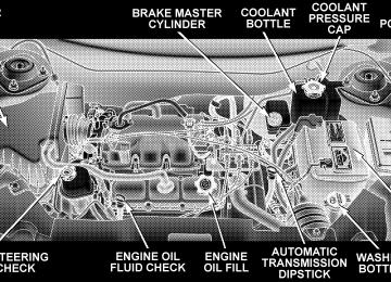
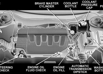
WARNING!
A hot engine cooling system is dangerous. You or others could be badly burned by steam or boiling coolant. You may want to call a service center if your vehicle overheats. If you decide to look under the hood yourself, see Section 7 of this manual. Follow the warnings under the Cooling System Pressure Cap paragraph.
3. Fuel Gauge The pointer shows the level of fuel in the fuel tank when the ignition switch is in the ON position.
The Low Fuel Light will turn on when the fuel level reaches approximately 2 to 4 gallons (7 to 15 liters) this light will remain on until fuel is added.
UNDERSTANDING YOUR INSTRUMENT PANEL 169
4. Turn Signal Indicators
The arrow will flash with the exterior turn signal when the turn signal lever is operated.
If the vehicle electronics sense that the vehicle has traveled about one mile with the turn signals on, a chime will sound to alert you to turn the signals off. If either indicator flashes at a rapid rate, check for a defective outside light bulb. 5. Speedometer Indicates vehicle speed. 6. Anti-Lock Light
This light monitors the Anti-Lock Brake Sys- tem. The light will turn on when the ignition switch is turned to the ON position and may stay on for as long as four seconds.
If the ABS light remains on or turns on while driving, it indicates that the Anti-Lock portion of the brake system
170 UNDERSTANDING YOUR INSTRUMENT PANEL
is not functioning and that service is required. However, the conventional brake system will continue to operate normally if the BRAKE warning light is not on. If the ABS light is on, the brake system should be serviced as soon as possible to restore the benefits of Anti-Lock brakes. If the ABS light does not turn on when the Ignition switch is turned to the ON position, have the light inspected by an authorized dealer. 7. Brake System Warning Light
This light monitors various brake functions, including brake fluid level and parking brake application. If the brake light turns on, it may indicate that the parking brake is applied, there is a low brake fluid level or there is a problem with the anit-lock brake system. The dual brake system provides a reserve braking capac- ity in the event of a failure to a portion of the hydraulic system. Failure of either half of the dual brake system is
indicated by the Brake Warning Light which will turn on when the brake fluid level in the master cylinder has dropped below a specified level. The light will remain on until the cause is corrected. NOTE: The light may flash momentarily during sharp cornering maneuvers which change fluid level condi- tions. The vehicle should have service performed. If brake failure is indicated, immediate repair is neces- sary.
WARNING!
Driving a vehicle with the brake light on is danger- ous. Part of the brake system may have failed. It will take longer to stop the vehicle. You could have an accident. Have the vehicle checked immediately.
Vehicles equipped with Anti-Lock brakes (ABS), are also equipped with Electronic Brake Force Distribution (EBD). In the event of an EBD failure, the Brake Warning Light will turn on along with the ABS Light. Immediate repair to the ABS system is required. The operation of the Brake Warning Light can be checked by turning the ignition switch from the OFF position to the ON position. The light should illuminate for approxi- mately two seconds. The light should then turn off unless the parking brake is applied or a brake fault is detected. If the light does not illuminate, have the light inspected by an authorized dealer. The light also will turn on when the parking brake is applied with the ignition switch in the ON position. NOTE: This light shows only that the parking brake is applied. It does not show the degree of brake application.
UNDERSTANDING YOUR INSTRUMENT PANEL 171
8. Traction Control Indicator — If Equipped
This display indicator illuminates momentarily as a bulb check when the ignition switch is first turned ON.
the system OFF.
The traction control Indicator will turn on if: • The traction control system is in use. • The Traction Control switch has been used to turn • There is a Traction Control System malfunction. • The system has been deactivated to prevent damage to the brake system due to overheated brake tem- peratures.
NOTE: Extended heavy use of Traction Control may cause the system to deactivate and turn on the Traction Control Light. This is to prevent overheating of the brake system and is a normal condition. The system will remain
172 UNDERSTANDING YOUR INSTRUMENT PANEL
disabled for about 4 minutes until the brakes have cooled. The system will automatically reactivate and turn off the Traction Control Light. 9. Tachometer The red segments indicate the maximum permissible engine revolutions-per-minute (r.p.m. x 1000) for each gear range. Before reaching the red area, ease up on the accelerator. 10. Trip Odometer Button Press this button to change the display from odometer to either of the two trip odometer settings. The word TRIP and either “A” or “B” will appear when in the trip odometer mode. Push in and hold the button for two seconds to reset the trip odometer to 0 miles or kilome- ters. The odometer must be in trip mode to reset.
11. Transmission Range Indicator This display indicator shows the automatic transmission gear selection. 12. AutoStick Light This display indicator illuminates when the gearshift lever is moved to the AutoStick position. 13. Odometer/Trip Odometer The odometer shows the total distance the vehicle has been driven. U.S. federal regulations require that upon transfer of vehicle ownership, the seller certify to the purchaser the correct mileage that the vehicle has been driven. There- fore, if the odometer reading is changed during repair or replacement, be sure to keep a record of the reading before and after the service so that the correct mileage can be determined.
The two trip odometers show individual trip mileage. To switch from odometer to trip odometers, press and release the Trip Odometer button. To reset a trip odom- eter, display the desired trip odometer to be reset then push and hold the button until the display resets (ap- proximately 2 seconds). Loose Fuel Filler Cap If the vehicle diagnostic system determines that the fuel filler cap is loose, improperly installed, or damaged, GASCAP will be displayed in the instrument cluster odometer. Tighten the fuel filler cap properly and press the odometer reset button to turn the GASCAP message off. If the problem continues, the message will appear the next time the vehicle is started. See Section 7 of this manual for more information. 14. Cruise Indicator This display indicator shows that the Speed Control System is ON.
UNDERSTANDING YOUR INSTRUMENT PANEL 173
15. Malfunction Indicator Light
This light is part of an onboard diagnostic system called OBD that monitors engine and automatic transmission control systems. The light will illu- minate when the key is in the ON position before engine start. If the bulb does not come on when turning the key from OFF to ON, have the condition checked promptly. Certain conditions such as a loose or missing gas cap, poor fuel quality, etc. may illuminate the light after engine start. The vehicle should be serviced if the light stays on through several of your typical driving cycles. In most situations the vehicle will drive normally and will not require towing. The Malfunction Indicator Light flashes to alert you to serious conditions that could lead to immediate loss of power or severe catalytic converter damage. The vehicle should be serviced as soon as possible if this occurs.
174 UNDERSTANDING YOUR INSTRUMENT PANEL
16. High Beam Light
This light shows that the headlights are on high beam. Pull the Multi-Function lever towards the steering wheel to switch the headlights from high or low beam. 17. Navigation Screen — If Equipped The navigation system provides maps, turn identifica- tion, selection menus and instructions for selecting a variety of destinations and routes. Refer to your “Navi- gation User’s Manual” for detailed operating instruc- tions. 18. Front Fog Light Indicator — If Equipped
This light shows the front fog lights are ON.
19. Oil Pressure Warning Light
This light shows low engine oil pressure. The light should turn on momentarily when the engine is started. If the light turns on while driving, stop the
vehicle and shut off the engine as soon as possible. A continuous chime will sound when this light turns on. Do not operate the vehicle until the cause is corrected. This light does not show how much oil is in the engine. The engine oil level must be checked under the hood. 20. Seat Belt Reminder Light
When the ignition switch is first turned ON, this light will turn on for 5 to 8 seconds as a bulb check. During the bulb check, if the driver’s seat belt is unbuckled, a chime will sound. After the bulb check or when driving, if the driver seat belt remains unbuckled, the Seat Belt Warning Light will flash or remain on continuously. Refer to ⬙Enhanced Driver Seat Belt Re- minder System (BeltAlert™)⬙ in the Occupant Restraints section for more information.
21. Tire Pressure Monitoring Telltale Lamp — If Equipped
Each tire, including the spare (if provided), should be checked monthly when cold and inflated to the inflation pressure recommended by the vehicle manufacturer on the vehicle placard or tire inflation pressure label. (If your vehicle has tires of a different size than the size indicated on the vehicle placard or tire inflation pressure label, you should determine the proper tire inflation pressure for those tires.) As an added safety feature, your vehicle has been equipped with a tire pressure monitoring system (TPMS) that illuminates a low tire pressure telltale when one or more of your tires is significantly under-inflated. Accord- ingly, when the low tire pressure telltale illuminates, you should stop and check your tires as soon as possible, and inflate them to the proper pressure. Driving on a signifi- cantly under-inflated tire causes the tire to overheat and
UNDERSTANDING YOUR INSTRUMENT PANEL 175
can lead to tire failure. Under-inflation also reduces fuel efficiency and tire tread life, and may affect the vehicle’s handling and stopping ability. Please note that the TPMS is not a substitute for proper tire maintenance, and it is the driver’s responsibility to maintain correct tire pressure, even if under-inflation has not reached the level to trigger illumination of the TPMS low tire pressure telltale. 22. Airbag Light
This light turns on and remains on for 6 to 8
seconds as a bulb check when the ignition switch is first turned ON. If the light is not on during starting, stays on, or turns on while driving, have the system inspected by an authorized dealer as soon as possible.176 UNDERSTANDING YOUR INSTRUMENT PANEL
23. Electronic Vehicle Information Center Display — If Equipped When the appropriate conditions exist, this display shows the Electronic Vehicle Information Center (EVIC) messages. 24. Engine Temperature Warning Light
This light warns of an overheated engine condi- tion. If this light is accompanied by a continuous chime, the engine temperature is critically hot, and the vehicle should be turned off immediately. The vehicle should be serviced as soon as possible. 25. Liftgate Ajar — If Equipped
This light turns on if the liftgate is not com- pletely closed.
26. Door Ajar Light — If Equipped
This light turns on if a door is not completely closed.
27. Washer Fluid Light — If Equipped
This light turns on when the washer fluid level falls below approximately 1/4 filled. The light will remain on until fluid is added.
ELECTRONIC VEHICLE INFORMATION CENTER (EVIC) — IF EQUIPPED The Electronic Vehicle Information Center (EVIC) con- sists of the following: • Vehicle information warning message displays • Tire Pressure Monitor System — If Equipped • Customer programmable features • Compass display • Mini-Trip functions
Pressing the MENU button will change the displayed programming features. Pressing the STEP button will display the available choices. Pressing the MENU button a second time accepts a selected choice. When the appropriate conditions exist, the Electronic Vehicle Information Center (EVIC) displays the following messages. • LEFT/RIGHT TURN SIGNAL ON (with a continuous • INVALID KEY & FOB (with a single chime) • PARK ASSIST DISABLED • SERVICE PARK ASSIST SYSTEM • SERVICE IMMOBILIZER (with a single chime) • KEY FOB BATTERY LOW (with a single chime) • KEY & FOB PROGRAMMED (with a single chime)
warning chime)
UNDERSTANDING YOUR INSTRUMENT PANEL 177
chime)
PARK (with a single chime)
• PROGRAM KEY & FOB • MEMORY #1/#2 POSITION SET (with a single chime) • MEMORY #1/#2 POS SELECTED • MEMORY SYSTEM DISABLED VEHICLE NOT IN • SET INHIBITED DUE TO MOTION (with a single • FOB LINKED (with a single chime) • FOB UNLINKED (with a single chime) • PARK BRAKE ENGAGED (with a single chime) • LOW BRAKE FLUID (with a single chime) • LOW FUEL (with a single chime) • MENU IN PARK ONLY • LIST # ALERT MESSAGES
178 UNDERSTANDING YOUR INSTRUMENT PANEL
chime)
• UNLOCK TO OPEN LIFTGATE (with a single chime) • PUT IN PARK FOR LIFTGATE (with a single chime) • TOO COLD FOR PWR LIFTGATE (with a single • TOO HOT FOR PWR LIFTGATE (with a single chime) • PERFORM SERVICE (with a single chime) • LEFT/RIGHT FRONT DOOR AJAR (one or more, • LEFT/RIGHT REAR DOOR AJAR (one or more, with a single chime if speed is above 1 mph) • DOOR(S) AJAR (with a single chime) • DOOR(S) AND GATE AJAR (with a single chime) • LIFT GATE AJAR (with a single chime if speed is
with a single chime if speed is above 1 mph)
above 1 mph)
chime)
• WASHER FLUID LOW (with a single chime) • PEDAL ADJUST DISABLED CRUISE ENGAGED • PEDAL ADJUST DISABLED VEHICLE IN REVERSE • CHANNEL 1, 2, OR 3 TRANSMIT (with a single • CHANNEL 1, 2, OR 3 TRAINING (with a single • CHANNEL 1, 2, OR 3 TRAINED (with a single chime) • CLEARING CHANNELS • CHANNELS CLEARED • CHANNELS DEFAULTED • DID NOT TRAIN
chime)
• 1,2,3 OR 4 TIRE(S) LOW PRESSURE (Refer to ”Tire Pressure Monitor System” in the “Starting And Oper- ating, Tire Section”) • CHECK TPM SYSTEM (Refer to ”Tire Pressure Moni- tor System” in the “Starting And Operating, Tire Section”) • TCS SUSPENDED (Traction Control System, with a • TCS ACTIVE (Traction Control System, with a • SERVICE TCS SYSTEM (Traction Control System, with
graphic and single chime)
graphic)
a graphic and single chime)
UNDERSTANDING YOUR INSTRUMENT PANEL 179
Customer Programmable Features — If Equipped Press the MENU button until one of the following display choices appears: Language? When in this display you may select one of three lan- guages for all display nomenclature, including the trip computer functions and navigation system. Press the STEP button while in this display selects English, Francais, or Espanol. As you continue the displayed information will be shown in the selected language. Park Assist System? ON/OFF When this feature is selected the system scans for objects behind the vehicle using four sensors located in the rear bumper. Objects can be detected from up to 71 inches (180 cm). Pressing the “STEP” button while in this display will disable/enable the Rear Park Assist System. The EVIC will display the following message: PARK
180 UNDERSTANDING YOUR INSTRUMENT PANEL
ASSIST DISABLED after the feature has been disabled and SERVICE PARK ASSIST SYSTEM if there is a prob- lem with the system. Display U.S. or Metric? Pressing the US/M button will change the EVIC, odom- eter, navigation system and A/C Control units from US to Metric. Use factory Settings? When in this display you may select to use the factory settings and no programmable features will be offered. Auto Door Locks? When this feature is selected, all doors and the liftgate lock automatically when the speed of the vehicle reaches 15 mph (25 km/h). Pressing the STEP button when in this display will select “Yes” or “No.”
Auto Unlock On Exit? When this feature is selected all the vehicle’s doors will unlock when the driver’s door is opened if the vehicle is stopped and the transmission is in P (Park) or N (Neu- tral) position. Pressing the STEP button when in this display will select “Yes” or “No.” Remote Unlock Driver’s Door 1st? When this feature is selected only the driver’s door will unlock on the first press of the remote keyless entry unlock button and require a second press to unlock the remaining locked doors and liftgate. When REMOTE UNLOCK ALL DOORS is selected all of the doors and the liftgate will unlock at the first press of the remote keyless entry unlock button. Pressing the STEP button when in this display will select DRIVER’S DOOR 1ST or ALL DOORS.
Remote Linked To Memory? (Available with Memory Seat Only) When this feature is selected the memory seat, mirror, and radio settings will return to the memory set position when the remote keyless entry “Unlock” button is pressed. If this feature is not selected then the memory seat, mirror, and radio settings can only return to the memory set position using the door mounted switch. Pressing the STEP button when in this display will select “Yes” or “No.” Sound Horn On Lock? When this feature is selected a short horn sound will occur when the remote keyless entry “Lock” button is pressed. This feature may be selected with or without the flash lights on lock/unlock feature. Pressing the STEP button when in this display will select “Yes” or “No.”
UNDERSTANDING YOUR INSTRUMENT PANEL 181
Flash Lights On Lock/Unlock? When this feature is selected, the front and rear turn signals will flash when the doors are locked or unlocked using the remote keyless entry transmitter. This feature may be selected with or without the sound horn on lock feature selected. Pressing the STEP button when in this display will select “Yes” or “No.” Headlamp Delay When this feature is selected the driver can choose, when exiting the vehicle, to have the headlamps remain on for 30, 60, or 90 seconds, or not remain on. Pressing the STEP button when in this display will select 30, 60, 90, or OFF. Headlamp On With Wipers? (Available with Auto Headlights Only) When this feature is selected and the headlight switch has at least once been moved to the AUTO position, the headlights will turn on in approximately 10 seconds when the wipers are turned on. The headlights will also
182 UNDERSTANDING YOUR INSTRUMENT PANEL
turn off when the wipers are turned off if they were turned on in this way. Pressing the STEP button when in this display will select “Yes” or “No.” NOTE: Turning the headlights on during the daytime causes the instrument panel lights to dim. To increase the brightness, refer to “Lights” in this section. Service Interval When this feature is selected a service interval between 2,000 miles (3 200 km) and 6, 000 miles (10 000 km) in 500
mile (800 km) increments may be selected. Pressing the STEP button when in this display will select distances between 2,000 miles (3 200 km) and 6, 000 miles (10 000
km) in 500 mile (800 km) increments.Reset Service Distance (Displays Only if Service Interval was Changed) When this feature is selected the current accumulated service distance can be reset to the newly selected service interval. Pressing the STEP button when in this display will select “Yes” or “No.” Power Accessory Delay? When this feature is selected, the power window switches, radio, hands–free system, DVD video system, power sunroof, and power outlets will remain active for up to 45 seconds after the ignition switch has been turned off. Opening a vehicle door or liftgate will cancel this feature. Easy Exit Seat? (Available with Memory Seat Only) This feature provides automatic driver’s seat positioning which will enhance driver mobility out of and into the vehicle.
The Easy Entry Easy Exit feature is not enabled when the vehicle is delivered from the factory. The Easy Entry Easy Exit feature is enabled (or later disabled) through the programmable features in the Electronic Vehicle Informa- tion Center (EVIC). Pressing the STEP button when in this display will select “Yes” or “No.” The seat will return to the memorized seat location (if REMOTE LINK TO MEMORY is set to YES) when the remote keyless entry transmitter is used to unlock the door. For more informa- tion refer to “Easy Entry/Exit Seat in the Driver Memory Seat section. Tilt Mirrors in Reverse? (Available with Memory Seat Only) When this feature is selected the outside mirrors will move slightly downward from the present position when the vehicle is shifted into the Reverse position. The outside mirrors will then return to the original position
UNDERSTANDING YOUR INSTRUMENT PANEL 183
when the vehicle is shifted out of Reverse position. Pressing the STEP button when in this display will select ⬙Yes⬙ or ⬙No⬙. Compass Display — If Equipped This display provides one of eight compass readings to indicate the direction the vehicle is facing. Automatic Compass Calibration This compass is self calibrating which eliminates the need to manually set the compass. When the vehicle is new, the compass may appear erratic and the EVIC will display “COMPASS CALIBRATING” until the compass is calibrated. The compass will calibrate automatically after approximately 40 seconds if no buttons are pressed and the vehicle is in Park. You may also calibrate the compass by completing one 360° turn in an area free from large metal or metallic objects, the “COMPASS CALI- BRATING” EVIC message will turn off and the compass will function normally.
184 UNDERSTANDING YOUR INSTRUMENT PANEL
Manual Compass Calibration If the compass appears erratic and the “COMPASS CALI- BRATING” message does not appear in the EVIC display, you must put the compass into the Calibration Mode manually. To put into a Calibration Mode: Turn on the ignition switch and set the display to Compass. Press the RESET button for at least 10 seconds until the “COMPASS CALIBRATING” message appears. Release the RESET button and complete one 360° turn in an area free from large metal objects. The “COMPASS CALIBRATING” message will turn off and the compass will function normally.
Compass Variance Compass Variance is the difference between magnetic North and Geographic North. In some areas of the country, the difference between magnetic and geographic North is great enough to cause the compass to give false readings. If this occurs, the compass variance must be set. NOTE: Magnetic materials should be kept away from the overhead console.
UNDERSTANDING YOUR INSTRUMENT PANEL 185
To set the variance: Turn the ignition switch ON and set the display to Compass. Press the RESET button for approximately 5 seconds but no more than 10 seconds. The “COMPASS VARIANCE” message and the last vari- ance zone number will be displayed. Press the STEP button to select the proper variance zone as shown in the map. Press the RESET button to set the new variance zone and resume normal operation. Mini-Trip Functions — If Equipped This displays information on the following: • Average Fuel Economy (ECO AVG) Shows the average fuel economy since the last reset. The minimum average fuel economy that will be displayed on reset is 0.3 mpg. • Distance To Empty (DTE) Shows the estimated distance that can be travelled with the fuel remaining in the tank. This estimated distance is determined using the MPG for the last few minutes.
186 UNDERSTANDING YOUR INSTRUMENT PANEL
• Off Mode Shows a blank display. • Step Button Push this button to cycle through all functions. To Reset The Display Pressing and releasing the Reset button once will clear the resettable function currently being displayed. The resettable function is average fuel economy. Reset will only occur if the resettable function is currently being displayed.
the Mini-trip
SETTING THE ANALOG CLOCK To set the analog clock at the top center of the instrument panel, press and hold the button until the setting is correct.
ELECTRONIC DIGITAL CLOCK
The clock and radio each use the display panel built into the radio. A digital readout shows the time in hours and minutes whenever the ignition switch is in the ON or ACC position and the time button is pressed. When the ignition switch is in the OFF position, or when the radio frequency is being displayed, time keeping is accurately maintained. Clock Setting Procedure
1. Turn the ignition switch to the ON or ACC position and press the time button. Using the tip of a ballpoint pen or similar object, press either the hour (H) or minute (M) buttons on the radio. 2. Press the H button to set hours or the M button to set minutes. The time setting will increase each time you press a button.
SALES CODE RAH—AM & FM STEREO RADIO WITH CD PLAYER AND CD/DVD CHANGER CONTROLS
NOTE: The radio sales code is located on the lower left side of your radio faceplate.
UNDERSTANDING YOUR INSTRUMENT PANEL 187
Radio Operation
Power/Volume Control Press the ON/VOL control to turn the radio on. Turn the volume control clockwise to increase the volume. NOTE: Power to operate the radio is supplied through the ignition switch. It must be in the ON or ACC position to operate the radio. PTY (Program Type) Pressing the INFO button once while in FM mode will turn on the PTY mode for 5 seconds. If no action is taken during the 5 second time out, the PTY icon will turn off. Pressing the TUNE button within 5 seconds will allow the program format type to be selected. Many radio stations do not currently broadcast PTY information.
RAH radio
188 UNDERSTANDING YOUR INSTRUMENT PANEL
Toggle the TUNE button to select the following format types:
Program Type
Radio Display
Adult Hits Classical Classic Rock College Country Information Jazz Foreign Language News Nostalgia Oldies Personality Public Rhythm and Blues
Adlt Hit Classicl Cls Rock College Country Inform Jazz Language News Nostalga Oldies Persnlty Public R & B
Program Type
Radio Display
Rel Musc Rel Talk Rock Soft Soft Rck Soft R&B Sports Talk Top 40
WeatherReligious Music Religious Talk Rock Soft Soft Rock Soft Rhythm and Blues Sports Talk Top 40
Weather By pressing the SEEK button when the PTY icon is displayed, the radio will be tuned to the next frequency station with the same selected PTY name. The PTY function only operates when in the FM and Satellite (if equipped) modes.The radio display will flash “SEEK” and the selected PTY program type when searching for the next PTY station. If no station is found with the selected PTY program type, the radio will return to the last preset station. If a preset button is activated while in the PTY (Program Type) mode, the PTY mode will be exited and the radio will tune to the preset station. Mode Press the MODE button to select between, AM, FM, CD, CD/DVD changer or the Satellite Radio (if equipped). When the Satellite Radio (if equipped) is selected “SA” will appear in your radio display. A disc may remain in the radio while in the Satellite or radio mode. Seek Press and release the SEEK button to search for the next station in either the AM, FM or Satellite mode. Press the
UNDERSTANDING YOUR INSTRUMENT PANEL 189
top of the button to seek up and the bottom to seek down. The radio will remain tuned to the new station until you make another selection. Holding the button in will by- pass stations without stopping until you release it. Tuning Press the TUNE control up or down to increase or decrease the frequency. If you press and hold the button, the radio will continue to tune until you release the button. The frequency will be displayed and continu- ously updated while the button is pressed. Balance The Balance control adjusts the left-to-right speaker bal- ance. Press the AUDIO button, select BALANCE, then press SEEK + or SEEK ⫺ to adjust the balance. Fade The Fade control provides for balance between the front and rear speakers. Press the AUDIO button, select FADE, then press SEEK + or SEEK ⫺ to adjust the fade balance.
190 UNDERSTANDING YOUR INSTRUMENT PANEL
Tone Control The Bass and/or Treble controls sound for the desired tone. Press the AUDIO button, select Bass or TREBLE, then press SEEK + or SEEK ⫺ to increase or decrease amplification of the band. To Set The Radio Push-Button Memory When you are receiving a station that you wish to commit to push-button memory, press the SET button. SET 1 will show in the display window. Select the push-button you wish to lock onto this station and press and release that button. If a station is not selected within 5 seconds after pressing the SET button, the station will continue to play but will not be locked into push-button memory. You may add a second station to each push-button by repeating the above procedure with this exception: Press the SET button twice and SET 2 will show in the display window. Each button can be set for SET 1 and SET 2 in
both AM and FM. This allows a total of 10 AM and 10 FM stations to be locked into memory. You can recall the stations stored in SET 2 memory by pressing the push- button twice. To Change From Clock To Radio Mode Press the TIME button to change the display between radio frequency and time. General Information This radio complies with Part 15 of FCC rules and with RSS-210 of Industry Canada. Operation is subject to the following conditions: 1. This device may not cause harmful interference, 2. This device must accept any interference received, including interference that may cause undesired opera- tion.
NOTE: Changes or modifications not expressively ap- proved by the party responsible for compliance could void the user’s authority to operate the equipment. CD Player Operation NOTE: • The ignition switch must be in the ON or ACC position and the volume control ON before the CD player will operate. • This Radio is capable of playing compact discs (CD), recordable compact discs (CD-R), rewritable compact discs (CD-RW) compact discs with MP3 tracks and multisession compact discs with CD and MP3 tracks.
UNDERSTANDING YOUR INSTRUMENT PANEL 191
Inserting The Compact Disc
CAUTION!
This CD player will accept only 4–3/4 inch (12cm) discs only. The use of other sized discs may damage the CD player mechanism.
You may either insert or eject a disc with the radio OFF. If you insert a disc with the ignition ON and the radio OFF, the display will show the time of day. If you insert a disc with the ignition OFF, the display will show the time of day for about 5 seconds, then go out. If the power is ON, the unit will switch from radio to CD mode and begin to play when you insert the disc. The display will show the track number and index time in minutes and seconds. Play will begin at the start of track one.
192 UNDERSTANDING YOUR INSTRUMENT PANEL
Seek Press the top of the SEEK button for the next selection on the CD. Press the bottom of the button to return to the beginning of the current selection, or return to the beginning of the previous selection if the CD is within the first 10 seconds of the current selection. EJT — Eject Press the EJT button and the disc will unload and move to the entrance for easy removal. The unit will switch to the radio mode. If you do not remove the disc within 15 seconds, it will be reloaded. The radio mode will continue to appear. The disc can be ejected with the radio OFF. FF/TUNE/RW Press FF (Fast Forward) and the CD player will begin to fast forward until FF is released. The RW ( Reverse) button works in a similar manner.
RND — Random Play Press the RND button while the CD is playing to activate Random Play. This feature plays the selections on the compact disc in random order to provide an interesting change of pace. Press the SEEK button to move to the next randomly selected track. Press TUNE FF to fast forward through the tracks. Press the FF button a second time to stop the fast forward feature. If TUNE RW is pressed, the current track will reverse to the beginning of the track and begin playing. Press the RND button a second time to stop Random Play.
CD/DVD Changer Operation Press the MODE button to select between the CD player and the optional remote CD/DVD changer. Time Press the TIME button to change the display from elapsed CD or DVD playing time to time of day. Notes On Playing MP3 Files The radio can play MP3 files, however, acceptable MP3
file recording media and formats are limited. When writing MP3 files, pay attention to the following restric- tions. Supported media (disc types) The MP3 file recording media supported by the radio are CD-ROM, CD-R and CD-RW. Supported medium formats (file systems) The medium formats supported by the radio are ISO 9660
Level 1 and Level 2 and includes the Joliet extension.UNDERSTANDING YOUR INSTRUMENT PANEL 193
When reading discs recorded using formats other than ISO 9660 Level 1 and Level 2, the radio may fail to read files properly and may be unable to play the file nor- mally. UDF and Apple HFS formats are not supported. The radio uses the following limits for file systems: • Maximum number of directory levels: 15
• Maximum number of files: 255
• Maximum number of folders: 100
• Maximum number of characters in file/folder names: • Level 1: 12 (including a separator ⬙.⬙ and a • Level 2: 31 (including a separator3-character extension)
⬙.⬙ and a
3-character extension)
194 UNDERSTANDING YOUR INSTRUMENT PANEL
Multisession disc formats are supported by the radio. Multisession discs may contain combinations of normal CD audio tracks and computer files (including MP3 files). Discs created with an option such as ⬙keep disc open after writing⬙ are most likely multisession discs. The use of multisession for CD audio or MP3 playback may result in longer disc loading times. Supported MP3 file formats The radio will recognize only files with the *.mp3 exten- sion as MP3 files. Non-MP3 files named with the *.mp3
extension may cause playback problems. The radio is designed to recognize the file as an invalid MP3 and will not play the file. When using the MP3 encoder to compress audio data to an MP3 file, the bit rate and sampling frequencies in the following table are supported. In addition, variable bitrates (VBR) are also supported. The majority of MP3 files use a 44.1 kHz sampling rate and a 192, 160, 128, 96 or VBR bit rates.
MPEG Specifi-
cation
Sampling Fre- quency (kHz)
MPEG-1 Audio
Layer 3
48, 44.1, 32
MPEG-2 Audio
Layer 3
24, 22.05, 16
Bit rate (kbps)
320, 256, 224, 192, 160, 128, 112, 96, 80, 64, 56, 48, 40, 32
160, 128, 144, 112, 96, 80, 64, 56, 48, 40, 32, 24,16, 8
ID3 Tag information for artist, song title and album title are supported for version 1 ID3 tags. ID3 version 2 is not supported by the radios. Playlist files are not supported. MP3 Pro files are not supported.
Playback of MP3 files When a medium containing MP3 data is loaded, the radio checks all files on the medium. If the medium contains a lot of folders or files, the radio will take more time to start playing the MP3 files. Loading times for playback of MP3 files may be affected by the following: • Media - CD-RW media may take longer to load than • Medium formats - Multisession discs may take longer • Number of files and folders - Loading times will
to load than non-multisession discs
CD-R media
increase with more files and folders
To increase the speed of disc loading, it is recommended to use CD-R media and single-session discs. To create a single-session disc, enable the Disc at Once option before writing to the disc.
UNDERSTANDING YOUR INSTRUMENT PANEL 195
Operation Instructions - (CD Mode For MP3 Audio Play)
SEEK Button (CD Mode For MP3 Play) Pressing the SEEK + button plays the next MP3 File. Pressing the SEEK ⫺ button plays the beginning of the MP3 file. Pressing the button within the first ten seconds plays the previous file. INFO Button (CD Mode For MP3 Play) Press and INFO button while playing MP3 disc. The radio scrolls through the following TAG information: Song Title, Artist, File Name, and Folder Name (if avail- able). Press the INFO button once more to return to ⬙elapsed time⬙ priority mode.
196 UNDERSTANDING YOUR INSTRUMENT PANEL
RW/FF (CD Mode For MP3 Play) Press the FF side of the button to move forward through the MP3 selection. Press the RW side of the button to move back through the MP3 selection. AM/FM Button (CD Mode For MP3 Play) Switches back to Radio mode. RND Button (CD Mode For MP3 Play) Pressing this button plays files randomly. DIR Button (CD Mode For MP3 Play) Press the DIR Button to display folders, when playing an MP3 discs that have a file/folder structure. Press DISC up (button 1) or DISC down (button 5) to move through the folders. Press the SET button to select a folder
Operating Instructions - Hands Free Phone (If Equipped) Refer to Hands Free Phone section of the Owner’s Manual. Operating Instructions - Satellite Radio Mode (If Equipped) Refer to the Satellite Radio section of Manual. Operating Instructions - Video Entertainment System (VES威) (If Equipped) Refer to 6 Disc CD/DVD Changer (RDV) section of the Owner’s Manual.
the Owner’s
SALES CODE REV AM & FM STEREO RADIO WITH CD PLAYER AND CD/DVD CHANGER CONTROLS
NOTE: The radio sales code is located on the lower left side of your radio faceplate.
UNDERSTANDING YOUR INSTRUMENT PANEL 197
Radio Operation
Power/Volume Control Press the ON/VOL control to turn the radio on. Turn the volume control clockwise to increase the volume. NOTE: Power to operate the radio is supplied through the ignition switch. It must be in the ON or ACC position to operate the radio. PTY (Program Type) Pressing the INFO button once while in FM mode will turn on the PTY mode for 5 seconds. If no action is taken during the 5 second time out, the PTY icon will turn off. Pressing the TUNE button within 5 seconds will allow the program format type to be selected. Many radio stations do not currently broadcast PTY information.
REV Radio
198 UNDERSTANDING YOUR INSTRUMENT PANEL
Toggle the TUNE button to select the following format types:
Program Type
Radio Display
Adult Hits Classical Classic Rock College Country Information Jazz Foreign Language News Nostalgia Oldies Personality Public Rhythm and Blues
Adlt Hit Classicl Cls Rock College Country Inform Jazz Language News Nostalga Oldies Persnlty Public R & B
Program Type
Radio Display
Rel Musc Rel Talk Rock Soft Soft Rck Soft R&B Sports Talk Top 40
WeatherReligious Music Religious Talk Rock Soft Soft Rock Soft Rhythm and Blues Sports Talk Top 40
Weather By pressing the SEEK button when the PTY icon is displayed, the radio will be tuned to the next frequency station with the same selected PTY name. The PTY function only operates when in the FM and Satellite (if equipped) modes.The radio display will flash “SEEK” and the selected PTY program type when searching for the next PTY station. If no station is found with the selected PTY program type, the radio will return to the last preset station. If a preset button is activated while in the PTY (Program Type) mode, the PTY mode will be exited and the radio will tune to the preset station. Mode Press the MODE button to select between, AM, FM, CD, CD/DVD changer or the Satellite Radio (if equipped). When the Satellite Radio (if equipped) is selected “SA” will appear in your radio display. A disc may remain in the radio while in the Satellite or radio mode. Seek Press and release the SEEK button to search for the next station in either the AM, FM or Satellite mode. Press the
UNDERSTANDING YOUR INSTRUMENT PANEL 199
top of the button to seek up and the bottom to seek down. The radio will remain tuned to the new station until you make another selection. Holding the button in will by- pass stations without stopping until you release it. Tuning Press the TUNE control up or down to increase or decrease the frequency. If you press and hold the button, the radio will continue to tune until you release the button. The frequency will be displayed and continu- ously updated while the button is pressed. Balance The Balance control adjusts the left-to-right speaker bal- ance. Press the AUDIO button, select BALANCE, then press SEEK + or SEEK ⫺ to adjust the balance. Fade The Fade control provides for balance between the front and rear speakers. Press the AUDIO button, select FADE, then press SEEK + or SEEK ⫺ to adjust the fade balance.
200 UNDERSTANDING YOUR INSTRUMENT PANEL
Tone Control The Bass and/or Treble controls sound for the desired tone. Press the AUDIO button, select Bass or TREBLE, then press SEEK + or SEEK ⫺ to increase or decrease amplification of the band. To Set The Radio Push-Button Memory When you are receiving a station that you wish to commit to push-button memory, press the SET button. SET 1 will show in the display window. Select the push-button you wish to lock onto this station and press and release that button. If a station is not selected within 5 seconds after pressing the SET button, the station will continue to play but will not be locked into push-button memory. You may add a second station to each push-button by repeating the above procedure with this exception: Press the SET button twice and SET 2 will show in the display window. Each button can be set for SET 1 and SET 2 in
both AM and FM. This allows a total of 10 AM and 10 FM stations to be locked into memory. You can recall the stations stored in SET 2 memory by pressing the push- button twice. To Change From Clock To Radio Mode Press the TIME button to change the display between radio frequency and time. General Information This radio complies with Part 15 of FCC rules and with RSS-210 of Industry Canada. Operation is subject to the following conditions: 1. This device may not cause harmful interference, 2. This device must accept any interference received, including interference that may cause undesired opera- tion.
NOTE: Changes or modifications not expressively ap- proved by the party responsible for compliance could void the user’s authority to operate the equipment. CD Player Operation NOTE: • The ignition switch must be in the ON or ACC position and the volume control ON before the CD player will operate. • This Radio is capable of playing compact discs (CD), recordable compact discs (CD-R), rewritable compact discs (CD-RW) compact discs with MP3 tracks and multisession compact discs with CD and MP3 tracks.
UNDERSTANDING YOUR INSTRUMENT PANEL 201
Inserting The Compact Disc
CAUTION!
This CD player will accept only 4–3/4 inch (12cm) discs only. The use of other sized discs may damage the CD player mechanism.
You may either insert or eject a disc with the radio OFF. If you insert a disc with the ignition ON and the radio OFF, the display will show the time of day. If you insert a disc with the ignition OFF, the display will show the time of day for about 5 seconds, then go out. If the power is ON, the unit will switch from radio to CD mode and begin to play when you insert the disc. The display will show the track number and index time in minutes and seconds. Play will begin at the start of track one.
202 UNDERSTANDING YOUR INSTRUMENT PANEL
Seek Press the top of the SEEK button for the next selection on the CD. Press the bottom of the button to return to the beginning of the current selection, or return to the beginning of the previous selection if the CD is within the first 10 seconds of the current selection. EJT — Eject Press the EJT button and the disc will unload and move to the entrance for easy removal. The unit will switch to the radio mode. If you do not remove the disc within 15 seconds, it will be reloaded. The radio mode will continue to appear. The disc can be ejected with the radio OFF. FF/TUNE/RW Press FF (Fast Forward) and the CD player will begin to fast forward until FF is released. The RW ( Reverse) button works in a similar manner.
RND — Random Play Press the RND button while the CD is playing to activate Random Play. This feature plays the selections on the compact disc in random order to provide an interesting change of pace. Press the SEEK button to move to the next randomly selected track. Press TUNE FF to fast forward through the tracks. Press the FF button a second time to stop the fast forward feature. If TUNE RW is pressed, the current track will reverse to the beginning of the track and begin playing. Press the RND button a second time to stop Random Play.
CD/DVD Changer Operation Press the MODE button to select between the CD player and the optional remote CD/DVD changer. Time Press the TIME button to change the display from elapsed CD or DVD playing time to time of day. Notes On Playing MP3 Files The radio can play MP3 files, however, acceptable MP3
file recording media and formats are limited. When writing MP3 files, pay attention to the following restric- tions. Supported media (disc types) The MP3 file recording media supported by the radio are CD-ROM, CD-R and CD-RW. Supported medium formats (file systems) The medium formats supported by the radio are ISO 9660
Level 1 and Level 2 and includes the Joliet extension.UNDERSTANDING YOUR INSTRUMENT PANEL 203
When reading discs recorded using formats other than ISO 9660 Level 1 and Level 2, the radio may fail to read files properly and may be unable to play the file nor- mally. UDF and Apple HFS formats are not supported. The radio uses the following limits for file systems: • Maximum number of directory levels: 15
• Maximum number of files: 255
• Maximum number of folders: 100
• Maximum number of characters in file/folder names: • Level 1: 12 (including a separator ⬙.⬙ and a • Level 2: 31 (including a separator3-character extension)
⬙.⬙ and a
3-character extension)
204 UNDERSTANDING YOUR INSTRUMENT PANEL
Multisession disc formats are supported by the radio. Multisession discs may contain combinations of normal CD audio tracks and computer files (including MP3 files). Discs created with an option such as ⬙keep disc open after writing⬙ are most likely multisession discs. The use of multisession for CD audio or MP3 playback may result in longer disc loading times. Supported MP3 file formats The radio will recognize only files with the *.mp3 exten- sion as MP3 files. Non-MP3 files named with the *.mp3
extension may cause playback problems. The radio is designed to recognize the file as an invalid MP3 and will not play the file. When using the MP3 encoder to compress audio data to an MP3 file, the bit rate and sampling frequencies in the following table are supported. In addition, variable bitrates (VBR) are also supported. The majority of MP3 files use a 44.1 kHz sampling rate and a 192, 160, 128, 96 or VBR bit rates.
MPEG Specifi-
cation
Sampling Fre- quency (kHz)
MPEG-1 Audio
Layer 3
48, 44.1, 32
MPEG-2 Audio
Layer 3
24, 22.05, 16
Bit rate (kbps)
320, 256, 224, 192, 160, 128, 112, 96, 80, 64, 56, 48, 40, 32