- Download PDF Manual
-
Using body pressure, move forward and rearward on the seat to be sure the seat adjusters have latched.
WARNING!
• Adjusting a seat while the vehicle is moving is dangerous. The sudden movement of the seat could cause you to lose control. The seat belt might not be properly adjusted and you could be injured. Adjust the seat only while the vehicle is parked. • Do not ride with the seatback reclined so that the shoulder belt is no longer resting against your chest. In a collision you could slide under the seat belt and be seriously or even fatally injured. Use the recliner only when the vehicle is parked.
UNDERSTANDING THE FEATURES OF YOUR VEHICLE 83
Driver’s Power Seat Height Adjuster — If Equipped The power seat height adjuster is on the outboard side of the driver’s seat. Use this switch to move the seat up or down.
Driver’s Power Seat Height Adjuster
84 UNDERSTANDING THE FEATURES OF YOUR VEHICLE
Reclining Bucket Seats The recliner control is on the outboard side of the seat. To recline, lean forward slightly before lifting the lever, then lean back to the desired position and release the lever. Lean forward and lift the lever to return the seatback to its normal position.
Folding Front Passenger Seat — If Equipped The passenger front seat may be folded fully forward to provide additional cargo space. To fold the seat forward pull up on the recliner lever located on the outboard side of the seat.
Recliner Control Lever
Folding Seat Control Lever
Adjustable Head Restraints Head restraints can reduce the risk of whiplash injury in the event of impact from the rear. Pull up or push down on the head restraints so that the upper edge is as high as practical. To raise the head restraint, pull up on the head restraint. To lower the head restraint, depress the button and push down on the head restraint.
UNDERSTANDING THE FEATURES OF YOUR VEHICLE 85
Adjustable Head Restraints
86 UNDERSTANDING THE FEATURES OF YOUR VEHICLE
Heated Seats — If Equipped This feature heats the front driver’s and passenger’s seats. The control for the heater is located on the out- board side of each seat. After turning on the ignition, you may choose from HIGH, or LOW heat settings. An indicator on the switch shows which setting has been chosen.
Heated Seat Switch
Press the switch once to select a heat setting (high or low) and press the switch a second time in the same direction to turn the heated seat off. NOTE: Once a heat setting is selected, heat will be felt within 2 to 3 minutes.
Folding Rear Seat To provide additional storage area, each rear seatback can be folded forward. Push and hold the buttons shown in the picture to fold down either or both seatbacks.
Folding Rear Seat Button
UNDERSTANDING THE FEATURES OF YOUR VEHICLE 87
WARNING!
• It is extremely dangerous to ride in a cargo area, inside or outside of a vehicle. In a collision, people riding in these areas are more likely to be seriously injured or killed. • Do not allow people to ride in any area of your vehicle that is not equipped with seats and seat belts • Be sure that everyone in your vehicle is in a seat
and using a seat belt properly.
NOTE: • If the rear center lap/shoulder belt appears to be locked into place, check to verify that the seatback is fully latched.
88 UNDERSTANDING THE FEATURES OF YOUR VEHICLE
• If the seatback is properly latched and the rear center lap/shoulder belt still does not operate properly check and see if the Automatic Locking retractor (ALR) system is activated.
WARNING!
The rear center lap/shoulder belt is equipped with a lock-out feature to ensure that the seatback is in the fully upright and locked position when occupied. If the rear seatback is not fully upright and locked and the rear center lap/shoulder belt can be pulled out of the retractor, the vehicle should immediately be taken to your dealer for service. Failure to follow this warning could result in serious or fatal injury.
Tumbling Rear Seat To provide additional storage in the cargo area, each rear seat can be tumbled forward.
CAUTION!
It is important that the front seats be pulled forward to the midpoint of the seat track to avoid contact between the rear seat and the front seatback. If the front seat is not pulled forward the two seats will make contact during the tumbling motion and cause damage to the rear seat material. After the rear seat is tumbled forward and secured the front seat can then be repositioned to the preferred position.
• Push and hold the button on the seatback and fold
down the rear seatback.
UNDERSTANDING THE FEATURES OF YOUR VEHICLE 89
• Pull the release handle located on the outboard side of the seat. Lift up the seat and tumble the seat forward.
Folding Rear Seat Button
Tumbling Seat Release Handle
90 UNDERSTANDING THE FEATURES OF YOUR VEHICLE
• Attach the elastic strap, located at the base of the seat cushion, onto the hook bar on the center trim panel to hold the seat in place.
To return the rear seat to it’s upright latched position, rotate the seat cushion rearward to latch the seat. Then lift the seatback to its upright latched position. NOTE: The elastic strap should be reinstalled in the clip on the base of the seat cushion before returning the seat to its normal position.
Tumbling Seat Strap
Rear Seat Removal The rear seats can be removed to provide more cargo space. • Push and hold the button on the seatback and fold
down the rear seatback.
UNDERSTANDING THE FEATURES OF YOUR VEHICLE 91
• Pull the release lever located on the outboard side of the seat. Lift up the seat and tumble the seat forward.
Tumbling Seat Release Handle
Folding Rear Seat Button
92 UNDERSTANDING THE FEATURES OF YOUR VEHICLE
• Lift up the release levers to disengage the seat from the
floor attachments.
• Using the handle on the seat, the seat assembly can
Release Lever Location
now be lifted and removed from the vehicle.
NOTE: Small rollers on the bottom of the folded seat and a handle at the top allow the seat to be easily moved when removed from the vehicle. To reinstall the rear seat, insert the seat into the floor attachments. Lower the release levers of the seat to latch the front floor attachments and rotate the seat rearward to latch the seat. Lift the seat back to its upright latched position.
WARNING!
In an accident, you or others in your vehicle could be injured if seats are not properly latched to their floor attachments. Always be sure the seats are fully latched.
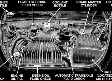
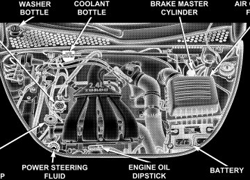
TO OPEN AND CLOSE THE HOOD To open the hood, two latches must be released. First pull the hood release lever located under the left side of the instrument panel.
UNDERSTANDING THE FEATURES OF YOUR VEHICLE 93
Then move the safety catch located under the front edge of the hood, near the center and slightly to the right, and raise the hood. Use the hood prop rod clipped to the driver’s side of the engine compartment to secure the hood in the open position. Place the hood prop at the location stamped into the inner hood surface. To prevent possible damage, do not slam the hood to close it. Lower the hood until it is open approximately 20
cm (8 inches) and then drop it. This should secure both latches. Never drive your vehicle unless the hood is fully closed, with both latches engaged.Hood Release Lever
94 UNDERSTANDING THE FEATURES OF YOUR VEHICLE
WARNING!
If the hood is not fully latched it could fly up when the vehicle is moving and block your forward vision. You could have a collision. Be sure all hood latches are fully latched before driving.
LIGHTS
Overhead Console Map/Reading Lights — If Equipped These lights are mounted between the sun visors in the overhead console. Each light is turned ON by pressing the lens. Press the lens a second time to turn the light OFF. The lights also come on when a door is opened or the dimmer control is turned fully upward, past the second detent.
Map/Reading Lights
NOTE: The lights will remain on until the switch is pressed a second time, so be sure they have been turned off before leaving the vehicle. They will not turn off automatically.
Interior Lights The interior lights come on when a door is opened. With the ignition key in the OFF position, the interior lights will automatically turn off in about 8 minutes if a door is left open or the dimmer control is left in the Dome light position. Turn the ignition switch ON to restore the interior light operation. Dimmer Control
With the parking lights or headlights on, rotating the dimmer control for the interior lights on the Multi-Function Control Lever upward will increase the brightness of the instrument panel lights.
tion.
UNDERSTANDING THE FEATURES OF YOUR VEHICLE 95
Dome Light Position
Rotate the dimmer control completely upward to the second detent to turn on the interior lights. The interior lights will remain on when the dim- mer control is in this position. With the ignition key in the OFF position, the interior lights will automatically turn off in about 8 minutes if the dimmer control is left in the Dome light posi-
96 UNDERSTANDING THE FEATURES OF YOUR VEHICLE
Interior light Defeat (OFF)
Rotate the dimmer control to the ex- treme bottom “OFF” position. The in- terior lights will remain off when the doors are open.
Parade Mode (Daytime Brightness Feature)
Rotate the dimmer control to the first detent (white semi-circle). This feature brightens the odometer and radio dis- play when the parking lights or head- lights are on during daylight condi- tions.
Multi-Function Control Lever The Multi-Function Control Lever controls the operation of the headlights, parking lights, turn signals, headlight beam selection, instrument panel light dimming, interior lights, the passing lights, and fog lights. The lever is located on the left side of the steering column. Headlights, Parking Lights, Instrument Panel Lights Turn the end of the Multi-Function Control Lever to the first detent for parking light operation. Turn to the second detent for headlight operation.
UNDERSTANDING THE FEATURES OF YOUR VEHICLE 97
Daytime Running Lights (Canada Only) The front turn signal lights will come on as Daytime Running Lights whenever the ignition switch is on, the headlights are off, and the parking brake is off. The headlight switch must be used for normal night time driving. Lights-on Reminder If the headlights or parking lights are on after the ignition is turned OFF, a chime will sound to alert the driver when the driver’s door is opened. Fog Lights — If Equipped
The front fog light switch is on the Multi-Function Control Lever. To activate the front fog lights, turn on the parking lights or the low beam headlights
and pull out the end of the control lever.
Multi-Function Control Lever
To change the brightness of the instrument panel lights, rotate the center portion of the Multi-Function Control Lever up or down.
98 UNDERSTANDING THE FEATURES OF YOUR VEHICLE
NOTE: The fog lights will only operate with the head- lights on low beam. Selecting high beam headlights will turn off the fog lights. Turn Signals Move the Multi-Function Control Lever up or down and the arrows on each side of the instrument cluster flash to show proper operation of the front and rear turn signal lights. You can signal a lane change by moving the lever partially up or down without moving beyond the detent. If either light remains on and does not flash, or there is a very fast flash rate, check for a defective outside light bulb. If an indicator fails to light when the lever is moved, it would suggest that the fuse or indicator bulb is defective.
Highbeam/Lowbeam Select Switch Pull the Multi-Function Control Lever towards you to switch the headlights to HIGH beam. Pull the control lever a second time to switch the headlights to LOW beam. Passing Light You can signal another vehicle with your headlights by lightly pulling the Multi-Function Control Lever toward you. This will cause the headlights to turn on at high beam and remain on until the lever is released.
WINDSHIELD WIPERS AND WASHERS
The wipers and washers are operated by a switch on the control lever. The lever is located on the right side of the steering column. Move the con-
trol lever up to select the desired wiper speed.
UNDERSTANDING THE FEATURES OF YOUR VEHICLE 99
If the lever is pulled while in the OFF position, the wipers will operate for two wipe cycles, then turn OFF. Mist Feature Push down on the wiper control lever to activate a single wipe to clear the windshield of road mist or spray from a passing vehicle. As long as the lever is held down, the wipers will continue to operate.
CAUTION!
In cold weather, always turn off the wiper switch and allow the wipers to return to the park position before turning off the engine. If the wiper switch is left on and the wipers freeze to the windshield, damage to the wiper motor may occur when the vehicle is restarted.
Windshield Wiper/Washer Control
Windshield Washers To use the washer, pull the control lever toward you and hold while spray is desired. If the lever is pulled while in the delay range, the wiper will operate in low speed for two wipe cycles after the lever is released, and then resume the intermittent interval previously selected.
TILT STEERING COLUMN To tilt the column, push down on the lever below the multi-function control lever and move the steering wheel up or down, as desired. Pull the lever back up to lock the column firmly in place.
100 UNDERSTANDING THE FEATURES OF YOUR VEHICLE
Windshield Wiper Operation Move the lever upward to the second detent for Low speed wiper operation, or to the third detent for High speed operation Intermittent Wiper System Use the intermittent wiper when weather conditions make a single wiping cycle, with a variable pause be- tween cycles, desirable. Move the lever to the DEL position, then select the delay interval by turning the end of the lever. Rotate the knob upward (clockwise) to decrease the delay time and downward (counterclock- wise) to increase the delay time. The delay can be regulated from a maximum of approximately 18 seconds between cycles, to a cycle every second.
Tilt Steering Column Control
WARNING!
Tilting the steering column while the vehicle is moving is dangerous. Without a stable steering col- umn, you could lose control of the vehicle and have an accident. Adjust the column only while the ve- hicle is stopped. Be sure it is locked before driving.
TRACTION CONTROL SWITCH — IF EQUIPPED The TRAC indicator, located in the instrument cluster, will flash when the Traction Control System is in use. The TRAC OFF switch is located on the instrument panel below the radio. To turn the system OFF, press the TRAC OFF switch until the TRAC OFF indicator in the instrument cluster lights up.
UNDERSTANDING THE FEATURES OF YOUR VEHICLE 101
Traction Control Switch
To turn the system back ON, press the switch a second time until the TRAC OFF indicator turns OFF.
102 UNDERSTANDING THE FEATURES OF YOUR VEHICLE
NOTE: The Traction Control System indicator “TRAC OFF” will illuminate momentarily as a bulb check, each time the ignition switch is turned ON. This will occur even if you used the “TRAC OFF” switch to turn the system OFF. NOTE: The Traction Control System will make buzzing or clicking sounds when the system is in operation.
ELECTRONIC SPEED CONTROL — IF EQUIPPED When engaged, this device takes over the accelerator operation at speeds greater than 25 mph (40 km/h). The speed control lever is located on the right side of the steering wheel.
Speed Control Switches
To Activate: Push the ON/OFF button. The CRUISE indicator in the instrument cluster will illuminate. To turn the system OFF, push the ON/OFF button a second time. The CRUISE indicator will turn off. The system should be turned OFF when not in use.
WARNING!
Leaving the Electronic Speed Control system on when not in use is dangerous. You could accidentally set the system or cause it to go faster than you want. You could lose control and have an accident. Always leave the system OFF when you are not using it.
To Set At A Desired Speed: When the vehicle has reached the desired speed, press down on the lever and release. Release the accelerator and the vehicle will operate at the selected speed. NOTE: The vehicle should be traveling at a steady speed and on level ground before pressing the SET lever. While in the AutoStick mode, speed control will only operate in third and fourth gear.
UNDERSTANDING THE FEATURES OF YOUR VEHICLE 103
To Deactivate: A soft tap on the brake pedal, pulling the speed control lever towards you “CANCEL”, or normal brake or clutch pressure while slowing the vehicle will deactivate speed control without erasing the set speed memory. Pressing the ON/OFF button or turning off the ignition switch erases the set speed memory. To Resume Speed: To resume a previously set speed, push the “ACC/RES” lever up and release. Resume can be used at any speed above 20 mph (32 km/h). To Vary The Speed Setting: When the speed control is ON, speed can be increased by pushing up and holding “ACC/RES”. Release the lever when the desired speed is reached, and the new speed will be set.
104 UNDERSTANDING THE FEATURES OF YOUR VEHICLE
Tapping “ACC/RES” once will result in a 2 mph (3
km/h) speed increase. Each time the lever is tapped, speed increases so that tapping the lever three times will increase speed by 6 mph (10 km/h), etc. To decrease speed while speed control is ON, push down and hold “COAST/SET”. Release the lever when the desired speed is reached, and the new speed will be set. Tapping the “COAST/SET” button once will result in a 1
mph (2 km/h) speed decrease. Each time the button is tapped, speed decreases. Manual Transaxle: Depressing the clutch pedal will disengage the speed control. A slight increase in engine RPM before the speed control disengages is normal. Vehicles equipped with manual transaxles may need to be shifted into a lower gear to climb hills without speed loss.WARNING!
Speed Control can be dangerous where the system can’t maintain a constant speed. Your vehicle could go too fast for the conditions, and you could lose control. An accident could be the result. Don’t use Speed Control in heavy traffic or on roads that are winding, icy, snow-covered, or slippery.
To Accelerate For Passing: Depress the accelerator as you would normally. When the pedal is released, the vehicle will return to the set speed. Using Speed Control On Hills NOTE: The speed control system maintains speed up and down hills. A slight speed change on moderate hills is normal.
Vehicles equipped with four speed automatic transaxles may experience a downshift to 3rd gear while climbing uphill or descending downhill. This downshift to 3rd gear is necessary to maintain vehicle set speed. On steep hills a greater speed loss or gain may occur so it may be preferable to drive without speed control.
GARAGE DOOR OPENER — IF EQUIPPED NOTE: The HomeLink威 system will be disabled if the Vehicle Theft Alarm (if equipped) is in the Prearmed, Armed or Alarming state. The HomeLink威 system will only operate when the Vehicle Theft Alarm (if equipped) is in the Disarmed mode. The HomeLink威 Universal Transceiver replaces up to three remote controls (hand held transmitters) that oper- ate devices such as garage door openers, motorized gates, or home lighting. It triggers these devices at the
UNDERSTANDING THE FEATURES OF YOUR VEHICLE 105
push of a button. The Universal Transceiver operates off your vehicle’s battery and charging system; no batteries are needed.
HomeLink Buttons
For additional information on HomeLink威, call 1–800– 355–3515, or on the internet at www.homelink.com.
106 UNDERSTANDING THE FEATURES OF YOUR VEHICLE
WARNING!
A moving garage door can cause injury to people and pets in the path of the door. People or pets could be seriously or fatally injured. Only use this transceiver with a garage door opener that has a “stop and reverse” feature as required by federal safety stan- dards. This includes most garage door opener mod- els manufactured after 1982. Do not use a garage door opener without these safety features it could cause injury or death. Call toll-free 1–800–355–3515
or, on the Internet at www.homelink.com for safety information or assistance.Programming The Universal Transceiver For best results, install a new battery in the hand held transmitter before programming. If your garage door opener (located in the garage) is equipped with an antenna, make sure that the antenna is hanging straight down. 1. Turn off the engine.
WARNING!
Vehicle exhaust contains carbon monoxide, a danger- ous gas. Do not run the vehicle’s exhaust while training the transceiver. Exhaust gas can cause seri- ous injury or death.
WARNING!
Your motorized door or gate will open and close while you are training the Universal Transceiver. Do not train the transceiver if people or pets are in the path of the door or gate. A moving door or gate can cause serious injury or death to people and pets or damage to objects.
2. Erase the factory test codes by pressing the two outside buttons. Release the buttons when the light in the Universal Transceiver begins to flash (about 20 seconds). NOTE: Step 2 does not have to be followed to program additional hand held transmitters. 3. Choose one of the three Universal Transceiver buttons to program. Place the hand held controller one to three inches from the Universal Transceiver while keeping its indicator light in view.
UNDERSTANDING THE FEATURES OF YOUR VEHICLE 107
HomeLink Programming
4. Using both hands, press the hand held transmitter button and the desired Universal Transceiver button. Do not release the buttons until step 5 has been completed. NOTE: Some entry gates and garage door openers may require you to replace step 4 with the procedures listed under Canadian Programming.
108 UNDERSTANDING THE FEATURES OF YOUR VEHICLE
5. The indicator light in the Universal Transceiver will begin to flash, first slowly and then rapidly. The rapid flashing indicates successful programming. If after 90
seconds the indicator light does not flash rapidly or goes out, return to step 1 and repeat the procedure. To train the other buttons, repeat steps 3 and 4. Be sure to keep your hand held transmitters in case you need to retrain the Universal Transceiver. NOTE: If you do not successfully program the Uni- versal Transceiver to learn the signal of your hand held transmitter, refer to the Rolling Code Paragraph, or call toll free for customer assistance at 1–800–355–3515, or on the internet at www.homelink.com. “Rolling Code” ProgrammingIf your hand held transmitter appears to pro- NOTE: gram the Universal Transceiver, but your garage door or other device does not operate, and your device was
manufactured after 1996, your garage door opener or other device may have a “Rolling Code” system. On garage door openers with the “Rolling Code” feature, the transmitter code changes after each use to prevent the copying of your code. To check if your device is protected by a “Rolling Code” system: • Check the owner’s manual for the device for mention • Press and hold the programmed button on the Univer- sal Transceiver. If the Universal Transceiver indicator light flashes rapidly and then stays on after 2 seconds, the device has the “Rolling Code” feature.
of “Rolling Codes”.
To train a garage door opener (or other rolling code equipped devices) with the rolling code feature, follow these instructions after completing the Programming portion of this text:
NOTE: The assistance of a second person may make the following programming procedure quicker and easier. 1. Locate the training button on the garage door motor head unit. The exact location and color of the button may vary by garage door opener manufacturer. If you have difficulty in locating the training button, check your garage door opener manual, or call 1-800-355-3515 or, on the Internet, at www.homelink.com. 2. Press and hold the training button on the garage door opener head unit. This will activate the “training” light. NOTE: After completing step 2, you have 30 seconds to start step 3. 3. Return to the Universal Transceiver in the vehicle and firmly press and release the garage door button. Press and release the button a second time to complete the
UNDERSTANDING THE FEATURES OF YOUR VEHICLE 109
training process. Some garage door openers may require you to do this procedure a third time to complete the training. Your garage door opener should now recognize your Universal Transceiver. The remaining two buttons may now be programmed if this has not previously been done. Refer to the Programming instructions. You may use either your Universal Transceiver or your original hand-held transmitter to open you garage door. Canadian Programming/Gate Programming Canadian frequency laws, and the technology of some entry gates, require you to press and release the hand held transmitter button every two seconds during pro- gramming. Continue to press and hold the Universal Transceiver button while you press and release the hand held trans- mitter button until the frequency signal has been learned.
110 UNDERSTANDING THE FEATURES OF YOUR VEHICLE
The Universal Transceiver light will flash slowly and then rapidly when the programming is successful. NOTE: When programming such a garage door opener or gate, unplug the device to prevent possible damage to the garage door or gate motor. Operation Press and hold the desired button on the Universal Transceiver until the garage door or other device begins to operate. The light in the display shows that the signal is being transmitted. The hand held transmitter may also be used at any time. Reprogramming A Single Button
1. Press and hold the Universal Transceiver button to be reprogrammed. Do not release until step 4 has been completed.
2. When the indicator light begins to flash slowly (after 20 seconds) position the hand held transmitter one to three inches away from the button to be trained. 3. Press and hold the hand held transmitter button. 4. The Universal Transceiver indicator light will begin to flash, first slowly, then rapidly. When the indicator lights begin to flash rapidly, release both buttons. Security If you sell your vehicle, be sure to erase the frequencies. To erase all of the previously trained frequencies, hold down both outside buttons until the indicator light begins to flash.
UNDERSTANDING THE FEATURES OF YOUR VEHICLE 111
OVERHEAD CONSOLE — IF EQUIPPED This feature has a compass/temperature display and two map lamps. The overhead console is located on the headliner between the sun visors.
This device complies with part 15 of FCC rules and with RS-210 of Industry Canada. Operation is subject to the following conditions: 1. This device may not cause harmful interference. 2. This device must accept any interference that may be received including interference that may cause undesired operation. NOTE: Changes or modifications not expressly ap- proved by the party responsible for compliance could void the user’s authority to operate the equipment. HomeLink威 is a trademark owned by Johnson Controls, Inc.
Overhead Console
STEP Button Functions:
112 UNDERSTANDING THE FEATURES OF YOUR VEHICLE
Compass/Temperature Display This display provides the outside temperature and one of eight compass readings to indicate the direction the vehicle is facing.
WARNING!
Even if the display still reads a few degrees above 32°F ( 0°C), the road surface may be icy, particularly in woods or on bridges. Drive carefully under such conditions to prevent an accident and possible per- sonal injury or property damage.
Step Button
1. US 2. Metric 3. Off 4. Magnetic Zone Selection 5. Manual Compass Calibration
UNDERSTANDING THE FEATURES OF YOUR VEHICLE 113
Automatic Compass Calibration The automatic calibrating feature of the compass elimi- nates the need to calibrate the compass due to normal varying conditions. Compass Variance Selection Variance is the difference between magnetic North and geographic North. For proper compass function, the correct variance zone must be set. Refer to the variance map for the correct variance zone. To check the variance zone, the ignition switch must be on and the compass/ temperature displayed. Press and hold the STEP button for about 5 to 10 seconds until ZONE and the number appears in the display. The number displayed is the variance zone used by the compass. To change the zone, press the STEP button to scroll through numbers 1
through 15. When the correct variance is selected release the step button and the Compass/Temperature display will re- turn to normal after approximately 15 seconds.114 UNDERSTANDING THE FEATURES OF YOUR VEHICLE
Manual Compass Calibration If the compass appears erratic, inaccurate, abnormal or the vehicle is new, you may calibrate the compass. Prior to calibrating the compass make sure the proper zone is selected. Refer to “Magnetic Zone Selection”.Find an open area away from large metal objects. With the vehicle running, press and hold the STEP button for (about 10 to 15 seconds). The display will illuminate the CAL indica- tor. Drive slowly (about 5 mph) in 3 complete 360 circles. The CAL indicator will turn off and the compass will be calibrated. NOTE: • The compass needs to go through a manual calibration to insure proper operation when taking vehicle deliv- ery.
• The STEP button must be pressed for 10 to 15 seconds to place the compass into CAL mode. Regardless of whether the CAL indicator is already illuminated.
Outside Temperature Because engine temperature can increase the displayed temperature, temperature readings are not updated when the vehicle is not moving. If the display shows ⫺49°F (⫺45°C) or 140°F (60°C), see your authorized dealer for repair.
POWER SUNROOF — IF EQUIPPED The power sunroof control is located between the sun visors on the overhead console.
UNDERSTANDING THE FEATURES OF YOUR VEHICLE 115
Press and hold the button in the center of the sunroof switch to open the vent. The sunroof can be stopped at any position between closed and full vent. To close the sunroof from the vent position, press and hold the switch forward. Releasing the switch will stop the movement of the sunroof and the sunroof will remain in the partial vent position until the switch is pushed forward again. Express Open Feature During the Express Open operation, any movement of the switch will stop the sunroof and it will remain in a partial open position. Again, momentarily pressing the switch rearward will activate the Express Open Feature. To close the sunroof, hold the switch in the forward position. Again, any release of the switch will stop the movement and the sunroof will remain in a partial open condition until the switch is pushed forward again.
Power Sunroof Switch
Press and hold the switch rearward to fully open the sunroof. The sunroof can be stopped at any position between closed and full open. Momentarily pressing the switch rearward will activate the Express Open Feature, causing the sunroof to open automatically.
116 UNDERSTANDING THE FEATURES OF YOUR VEHICLE
The sunshade can be opened manually. It will also open as the sunroof opens. The sunshade cannot be closed if the sunroof is open.
WARNING!
Never leave children in a vehicle, with the keys in the ignition switch. Occupants, particularly unat- tended children, can become entrapped by the power sunroof while operating the power sunroof switch. Such entrapment may result in serious injury or death.
WARNING!
In an accident, there is a greater risk of being thrown from a vehicle with an open sunroof. You could also be seriously injured or killed. Always fasten your seat belt properly and make sure all passengers are properly secured too. Do not allow small children to operate the sunroof. Never allow fingers or other body parts, or any object to project through the sunroof opening. Injury may result.
UNDERSTANDING THE FEATURES OF YOUR VEHICLE 117
ELECTRICAL POWER OUTLETS The outlets include tethered caps, labeled with a key symbol or battery symbol, indicating power source. All outlets are protected by a single 20 Amp fuse. The standard outlet in the front of the center floor console is a conventional cigar lighter outlet.
Wind Buffeting Wind buffeting can be described as the perception of pressure on the ears or a helicopter type sound in the ears. Your vehicle may exhibit wind buffeting with the windows down, or the sunroof (if equipped) in certain open or partially open positions. This is a normal occur- rence and can be minimized. If the buffeting occurs with the rear windows open, open the front and rear windows together to minimize the buffeting. If the buffeting occurs with the sunroof open, adjust the sunroof opening to minimize the buffeting or open any window. Sunroof Maintenance Use only a non-abrasive cleaner and a soft cloth to clean the glass panel.
Power Outlet
118 UNDERSTANDING THE FEATURES OF YOUR VEHICLE
It will accept a cigar lighter unit, which is part of the optional Smokers Package. To preserve the heating ele- ment of the cigar lighter unit, do not hold the lighter in the heating position. As a child safety precaution, this outlet is powered by the ignition switch, only when the switch is in the ⬙ON⬙ or ⬙ACCESSORY⬙ positions. There are two optional power outlets. One is in the Accessory Switch Bank, in the center of the instrument panel.
Power Outlet
This outlet is powered directly by the battery, regardless of the ignition switch position. All accessories connected to this outlet should be removed or turned off when the vehicle is not in use, to protect the battery against discharge.
The second is in the right rear cargo area.
Electrical Outlet Use With Engine Off
UNDERSTANDING THE FEATURES OF YOUR VEHICLE 119
CAUTION!
• Many accessories that can be plugged in draw power from the vehicle’s battery, even when not in use (i.e. cellular phones, etc.). Eventually, if plugged in long enough, the vehicle’s battery will discharge sufficiently to degrade battery life and/or prevent engine starting. • Accessories that draw higher power (i.e. coolers, vacuum cleaners, lights, etc.), will degrade the battery even more quickly. Only use these inter- mittently and with greater caution. • After the use of high power draw accessories, or long periods of the vehicle not being started (with accessories still plugged in), the vehicle must be driven a sufficient length of time to allow the generator to recharge the vehicle’s battery.
Rear Power Outlet
Since this outlet is remote from the driver, it is powered by the ignition switch, only when it is in the ⬙ON⬙ or ⬙ACCESSORY⬙ positions, to protect the battery against discharge. Note: Neither of the power outlets will accept a cigar lighter unit. They are intended only for accessory usage.
120 UNDERSTANDING THE FEATURES OF YOUR VEHICLE
CONSOLE FEATURES The console has two front cup holders, a coin holder, 12
volt power outlet and a front storage tray. There are additional cup holders; one is molded in the center of the console to hold large cups and the other is at the rear of the console to serve passengers in the rear seat. The floor console power outlet will also operate a conventional cigar lighter unit (if equipped with an optional Smoker’s Package).Front Cupholders
CAUTION!
• Many accessories that can be plugged into the 12
volt power outlet, draw power from the vehicle’s battery, even when not in use; i.e. cellular phones, etc. Eventually, if plugged in long enough, the vehicle’s battery will discharge sufficiently to degrade battery life and/or prevent engine start- ing. • Accessories that draw higher power such as cool- ers, vacuum cleaners, lights, etc., will discharge the battery even more quickly. Only use these intermittently and with greater caution. • After the use of high power draw accessories, or long periods of the vehicle not being started, (with accessories still plugged in), the vehicle must be driven a sufficient length of time to allow the generator to recharge the vehicle’s battery.UNDERSTANDING THE FEATURES OF YOUR VEHICLE 121
STORAGE
Front Seat Storage Bin — If Equipped
Front Seat Storage Bin
The storage bin is located under the front passenger’s seat. To open lift up on the handle and pull the storage bin forward.
122 UNDERSTANDING THE FEATURES OF YOUR VEHICLE
Storage Pockets There are also Storage pockets located on each door trim panel.
REAR SHELF PANEL The rear shelf panel attaches to guides in the rear cargo area. The rear shelf panel may be installed in one of five different positions. NOTE: The liftgate may be opened or closed with the rear cargo shelf panel in position 1, position 2, position 3
or position 4.WARNING!
positions.
• To avoid tipping, lock the shelf securely in all • Do not drive this vehicle with the liftgate open, or • Failure to follow these warnings could result in
use the shelf as a seat.
serious or fatal injury.
Position 1 (Top) Insert the front outboard corners of the shelf panel into the top guides and slide forward. Press down on the back of the shelf panel to lock it into place.
UNDERSTANDING THE FEATURES OF YOUR VEHICLE 123
Position 2 (Middle) Insert the front outboard corners of the shelf panel into the middle guides and slide forward. Press down on the back of the shelf panel to lock it into place.
Rear Shelf Panel Position 1
WARNING!
Do not load objects on the shelf in position 1 (top). In an accident objects could strike occupants causing serious or fatal injury.
Rear Shelf Panel Position 2
124 UNDERSTANDING THE FEATURES OF YOUR VEHICLE
WARNING!
Do not load objects over 100 lbs (45 kg) in position 2
(middle). Failure to follow this warning could cause the shelf to collapse resulting in personal injury.Position 3 (Floor) Insert the front outboard corners of the shelf panel into the bottom guides and slide forward. NOTE: To carry items that may soil the carpeting, the rear shelf panel may be inverted in position 2 or position 3. Position 4 (Vertical) Insert the front outboard corners of the shelf panel into the vertical guides behind the rear seatbacks near the floor and slide downward. Push the shelf panel forward to lock it into place.
Rear Shelf Panel Position 4
WARNING!
When in the vertical position, the rear shelf panel should not be used as a barrier for large objects in the cargo area when the seatbacks folded down. In an accident objects could strike the seatbacks or occupants causing serious or fatal injury.
Position 5 (table) With the liftgate open the rear shelf panel can be moved rearward to act as a serving counter. 1. Install the front corners of the shelf panel into the top rear guides. Press down on the shelf panel to lock it into place.
UNDERSTANDING THE FEATURES OF YOUR VEHICLE 125
2. Twist the knob on the underside of the panel and lower the shelf leg.
Rear Shelf Leg Release Knob
126 UNDERSTANDING THE FEATURES OF YOUR VEHICLE
3. Install the shelf leg into the liftgate latch area as labeled on the rear scuff plate.
Rear Shelf Panel Position 5
WARNING!
Do not load objects over 100 lbs (45 kg) in position 5
(table). Failure to follow this warning could cause the shelf to collapse resulting in personal injury.ROOF LUGGAGE RACK — IF EQUIPPED The crossbars and siderails are designed to carry the weight on vehicles equipped with a luggage rack. The load must not exceed 150 lbs (68 kg), and should be uniformly distributed over the luggage rack crossbars. Use both adjustable crossbars assemblies to support the load and distribute the load as evenly as possible. To adjust the crossbars with latch style releases, release the latches on the inboard side of the crossbar supports on each side of the vehicle, then move the crossbars to the desired position. Once the crossbar is in the desired position, return both latches to the locked position.
To adjust the crossbars with botton style releases, depress the button and slide the crossbar to the next locking position. Alternate sides until the crossbars are posi- tioned correctly for your cargo and the stanchions are locked square to the slide rails. External racks do not increase the total load carrying capacity of the vehicle. Be sure that the total occupant and luggage load inside the vehicle, plus the load on the luggage rack, do not exceed the rated vehicle capacity. NOTE: When the luggage rack is not in use, place the crossbars together at the rear of the vehicle. In this position they are designed to improve the vehicle aero- dynamics and reduce wind noise.
UNDERSTANDING THE FEATURES OF YOUR VEHICLE 127
CAUTION!
To avoid damage to the roof rack and vehicle, do not exceed the maximum roof rack load capacity of 150
lbs (68 kg). Always distribute heavy loads as evenly as possible and secure the load appropriately. Long loads which extend over the windshield, such as wood panels or surfboards, should be secured to both the front and rear of the vehicle. Travel at reduced speeds and turn corners carefully when carrying large or heavy loads on the roof rack. Wind forces, due to natural causes or nearby truck traffic, can add sudden upward loads. This is espe- cially true on large flat loads and may result in damage to the cargo or your vehicle.128 UNDERSTANDING THE FEATURES OF YOUR VEHICLE
WARNING!
Cargo must be securely tied before driving your vehicle. Improperly secured loads can fly off the vehicle, particularly at high speeds, resulting in personal injury or property damage. Follow the roof rack “Cautions” when carrying cargo on your roof rack.
UNDERSTANDING YOUR INSTRUMENT PANEL
CONTENTS
䡵 Instrument Panel Features . . . . . . . . . . . . . . . . . 133
䡵 Instrument Cluster . . . . . . . . . . . . . . . . . . . . . . 134
䡵 Instrument Cluster—Turbo, With AutoStick . . . . 135
䡵 Instrument Cluster—Turbo, Without AutoStick . . 136
䡵 Instrument Cluster Descriptions . . . . . . . . . . . . 137
䡵 Electronic Digital Clock . . . . . . . . . . . . . . . . . . 144
▫ Clock Setting Procedure . . . . . . . . . . . . . . . . . 144
䡵 Radio General Information . . . . . . . . . . . . . . . . 144
▫ Radio Broadcast Signals . . . . . . . . . . . . . . . . . 144▫ Two Types Of Signals . . . . . . . . . . . . . . . . . . 145
▫ Electrical Disturbances . . . . . . . . . . . . . . . . . . 145
▫ AM Reception . . . . . . . . . . . . . . . . . . . . . . . 145
▫ FM Reception . . . . . . . . . . . . . . . . . . . . . . . . 145䡵 Sales Code RBB—AM/FM Stereo Radio With
Cassette Tape Player And CD Changer Capability . . . . . . . . . . . . . . . . . . . . . . . . . . . . 146
▫ Radio Operation . . . . . . . . . . . . . . . . . . . . . . 146
▫ Mode Button . . . . . . . . . . . . . . . . . . . . . . . . 148
▫ Scan Button (Radio Mode) . . . . . . . . . . . . . . . 148130 UNDERSTANDING YOUR INSTRUMENT PANEL
▫ Cassette Player Features ▫ CD Changer Control Capability
. . . . . . . . . . . . . . . . 149
— If Equipped . . . . . . . . . . . . . . . . . . . . . . . 150
䡵 Sales Code RAZ—AM/ FM Stereo Radio With
Cassette Tape Player, CD Player And CD Changer Controls . . . . . . . . . . . . . . . . . . . . . . . . . . . . . 152
▫ Operating Instructions — Radio . . . . . . . . . . . 152
▫ Power Switch, Volume Control . . . . . . . . . . . . 153
▫ Seek Button (Radio Mode) . . . . . . . . . . . . . . . 153
▫ Tuning . . . . . . . . . . . . . . . . . . . . . . . . . . . . . 153
▫ Radio Data System (RDS) . . . . . . . . . . . . . . . 153
▫ PTY (Program Type) Button . . . . . . . . . . . . . . 154
▫ Balance . . . . . . . . . . . . . . . . . . . . . . . . . . . . 155
▫ Fade . . . . . . . . . . . . . . . . . . . . . . . . . . . . . . 155▫ Tone Control . . . . . . . . . . . . . . . . . . . . . . . . 155
▫ AM/FM Selection . . . . . . . . . . . . . . . . . . . . . 156
▫ Scan Button . . . . . . . . . . . . . . . . . . . . . . . . . 156
▫ To Set The Radio Push-Button Memory . . . . . . 156
▫ To Change From Clock To Radio Mode . . . . . . 157
▫ Operating Instructions — Tape Player . . . . . . . 157
▫ Seek Button . . . . . . . . . . . . . . . . . . . . . . . . . 157
▫ Fast Forward (FF) . . . . . . . . . . . . . . . . . . . . . 157
▫ Rewind (RW) . . . . . . . . . . . . . . . . . . . . . . . . 157
▫ Tape Eject . . . . . . . . . . . . . . . . . . . . . . . . . . . 158
▫ Scan Button . . . . . . . . . . . . . . . . . . . . . . . . . 158
▫ Changing Tape Direction . . . . . . . . . . . . . . . . 158
▫ Metal Tape Selection . . . . . . . . . . . . . . . . . . . 158▫ Pinch Roller Release . . . . . . . . . . . . . . . . . . . 158
▫ Noise Reduction . . . . . . . . . . . . . . . . . . . . . . 158
▫ Operating Instructions — CD Player . . . . . . . . 159
▫ Inserting The Compact Disc . . . . . . . . . . . . . . 159
▫ Seek Button . . . . . . . . . . . . . . . . . . . . . . . . . 160
▫ EJT CD (Eject) Button . . . . . . . . . . . . . . . . . . 160
▫ FF/Tune/RW . . . . . . . . . . . . . . . . . . . . . . . . 160
▫ Program Button 4 (Random Play) . . . . . . . . . . 160
▫ Mode . . . . . . . . . . . . . . . . . . . . . . . . . . . . . . 161
▫ Tape CD Button . . . . . . . . . . . . . . . . . . . . . . 161
▫ Time Button . . . . . . . . . . . . . . . . . . . . . . . . . 161
▫ Scan Button . . . . . . . . . . . . . . . . . . . . . . . . . 161UNDERSTANDING YOUR INSTRUMENT PANEL 131
▫ CD Changer Control Capability
— If Equipped . . . . . . . . . . . . . . . . . . . . . . . 161
䡵 Sales Code RBK—AM/ FM Stereo Radio With
CD Player And CD Changer Controls . . . . . . . . 163
▫ Radio Operation . . . . . . . . . . . . . . . . . . . . . . 163
▫ CD Player Operation . . . . . . . . . . . . . . . . . . . 165
▫ CD Changer Control Capability— If Equipped . . . . . . . . . . . . . . . . . . . . . . . 167
䡵 Sales Code RBQ—AM/FM Stereo Radio With
6 - Disc CD Changer . . . . . . . . . . . . . . . . . . . . 169
▫ Radio Operation . . . . . . . . . . . . . . . . . . . . . . 170
▫ CD Player Operation . . . . . . . . . . . . . . . . . . . 172䡵 Sales Code RB1—AM/FM Stereo Radio With
DVD/GPS Navigation System . . . . . . . . . . . . . . 177
132 UNDERSTANDING YOUR INSTRUMENT PANEL
䡵 Satellite Radio — If Equipped . . . . . . . . . . . . . . 177
▫ System Activation . . . . . . . . . . . . . . . . . . . . . 178
▫ Electronic Serial Number/Sirius IdentificationNumber (ENS/SID) . . . . . . . . . . . . . . . . . . . . 178
▫ Selecting Satellite Mode In RBB, RAH And
RBK Radios . . . . . . . . . . . . . . . . . . . . . . . . . 179
▫ Selecting Satellite Mode In RBP, RBU, RAZ,
RB1 And RBQ Radios . . . . . . . . . . . . . . . . . . 179
▫ Selecting a Channel . . . . . . . . . . . . . . . . . . . . 179
▫ Storing And Selecting Pre-Set Channels . . . . . . 180
▫ Using The PTY (Program Type) Button(If Equipped)
. . . . . . . . . . . . . . . . . . . . . . . . 180
▫ PTY Button ⬙Scan⬙ . . . . . . . . . . . . . . . . . . . . . 180
▫ PTY Button ⬙Seek⬙ . . . . . . . . . . . . . . . . . . . . . 180▫ Satellite Antenna . . . . . . . . . . . . . . . . . . . . . . 181
▫ Reception Quality . . . . . . . . . . . . . . . . . . . . . 181
䡵 Cassette Tape And Player Maintenance . . . . . . . 181
䡵 CD/DVD Disc Maintenance . . . . . . . . . . . . . . . 182
䡵 Radio Operation And Cellular Phones . . . . . . . . 183
䡵 Climate Controls . . . . . . . . . . . . . . . . . . . . . . . 183
▫ Air Conditioning . . . . . . . . . . . . . . . . . . . . . 183
▫ Operating Tips . . . . . . . . . . . . . . . . . . . . . . . 188
䡵 Rear Window Features . . . . . . . . . . . . . . . . . . . 190
▫ Electric Rear Window Defroster . . . . . . . . . . . 190
▫ Rear Wiper/Washer Switch . . . . . . . . . . . . . . 191
▫ Adding Washer Fluid . . . . . . . . . . . . . . . . . . 192INSTRUMENT PANEL FEATURES
UNDERSTANDING YOUR INSTRUMENT PANEL 133
134 UNDERSTANDING YOUR INSTRUMENT PANEL
INSTRUMENT CLUSTER
INSTRUMENT CLUSTER—TURBO, WITH AUTOSTICK
UNDERSTANDING YOUR INSTRUMENT PANEL 135
136 UNDERSTANDING YOUR INSTRUMENT PANEL
INSTRUMENT CLUSTER—TURBO, WITHOUT AUTOSTICK
INSTRUMENT CLUSTER DESCRIPTIONS
1. Fuel Gauge
When the ignition switch is in the ON position, the pointer will show the level of fuel remaining in the fuel tank.
2. Charging System Light
This light shows the status of the electrical charg- ing system. The light should come on briefly when the ignition is first turned ON and remain on briefly as a bulb check. If the light stays on or comes on while driving, there is a problem with the charging system. Obtain SERVICE IMMEDIATELY. 3. Deck Lid/Liftgate Ajar
it means that
This light comes on if the liftgate is not com- pletely closed.
UNDERSTANDING YOUR INSTRUMENT PANEL 137
4. Oil Pressure Light
Shows low engine oil pressure. The light will come on and remain on when the ignition switch is turned from the OFF to the ON position, and the light will turn off after the engine is started. If the bulb does not come on during starting, have the system checked by an authorized dealer. If the light comes on and remains on while driving, stop the vehicle and shut off the engine. DO NOT OPERATE THE VEHICLE UNTIL THE CAUSE IS CORRECTED. The light does not show the quantity of oil in the engine. This can be determined using the procedure shown in Section 7. (See page 269 for more information.) 5. Theft Alarm Light — If Equipped This light will flash rapidly for several seconds when the alarm system is arming. The light will begin to flash slowly indicating that the system is armed. (See page 26
for more information.)138 UNDERSTANDING YOUR INSTRUMENT PANEL
6. Engine Temperature Warning Light
This light warns of an overheated engine condi- tion. If the engine is critically hot, a warning chime will sound 10 times. After the chime turns off, the engine will still be critically hot until the light goes out. 7. Turn Signal Indicators
The arrows will flash in unison with the exterior turn signal, when using the turn signal lever.
NOTE: Turn signal bulbs are located in the Instrument Panel. (See page 98 for more information.) 8. Temperature Gauge
The temperature gauge shows engine coolant tem- perature. Any reading below the red area of the gauge shows that the engine cooling system is operating properly. The gauge pointer may show a higher than normal temperature when driving in hot weather, up mountain grades, in heavy stop and go traffic, or when towing a trailer.
If the pointer rises to the H (red) mark, the instrument cluster will sound a chime. Pull over and stop the vehicle. Idle the vehicle with the air conditioner turned off until the pointer drops back into the normal range. If the pointer remains on the H (red) mark, turn the engine off immediately and call for service. There are steps that you can take to slow down an impending overheat condition. If your air conditioning is on, turn it off. The air conditioning system adds heat to the engine cooling system and turning off the A/C removes this heat. You can also turn the Temperature control to maximum heat, the Mode control to Floor and the Fan control to High. This allows the heater core to act as a supplement to the radiator and aids in removing heat from the engine cooling system. 9. Speedometer Indicates vehicle speed.
10. High Beam Indicator
This light shows that the headlights are on high beam. Pull the turn signal lever toward the steer- ing wheel to switch the headlights from high or low beam. 11. Tachometer The white area of the scale shows the permissible engine revolutions-per-minute (rpm x 1000) for each gear range. Before reaching the red area, ease up on the accelerator to prevent engine damage. 12. Anti-Lock Warning Light (ABS) — If Equipped
This light monitors the Anti-Lock Brake System (ABS) described elsewhere in this manual. This light will come on when the ignition key is turned to the ON position and may stay on for
as long as four seconds. If the ABS light remains on or comes on during driving, it indicates that the Anti-Lock portion of the brake system
UNDERSTANDING YOUR INSTRUMENT PANEL 139
is not functioning and that service is required, however, the conventional brake system will continue to operate normally provided that the BRAKE warning light is not on. If the ABS light is on, the brake system should be serviced as soon as possible to restore the benefit of Anti-Lock Brakes. The warning light should be checked frequently to assure that it is operating properly. Turn the ignition key to the on position, but do not start the vehicle. The light should come on. If the light does not come on, have the system checked by an authorized dealer. 13. Seat Belt Reminder Light
When the ignition switch is first turned ON, this light will come on for about six seconds. A chime will sound if you have not pulled the shoulder belt out of the retractor. This is a reminder to “buckle up”. If you do not buckle up, the light will remain on.
140 UNDERSTANDING YOUR INSTRUMENT PANEL
14. Brake System Warning Light
This light monitors various brake functions, including brake fluid level and parking brake application. If the brake light comes on, it may indicate that the parking brake is applied, or there is a low brake fluid level. On vehicles equipped with Anti-lock brakes (ABS), it may also indicate an ABS malfunction that could lead to reduced braking perfor- mance.
WARNING!
Driving a vehicle with the brake light on is danger- ous. A significant decrease in braking performance or vehicle stability during braking may occur. It will take you longer to stop the vehicle or will make your vehicle harder to control. You could have an acci- dent. Have the vehicle checked immediately.
The operation of the Brake Warning light can be checked by turning the ignition key from the OFF to the ON position. The light should illuminate for three seconds, or until the engine is started, whichever comes first. The light should then go out unless the parking brake is applied or a brake fault is detected. If the light does not illuminate, have the light inspected and serviced as soon as possible. The light will also come on when the parking brake is applied with the ignition switch in the ON position. NOTE: This light shows only that the parking brake is applied. It does not show the degree of brake application. If the parking brake is off and the light remains on, have the brake system inspected as soon as possible. 15. Trac Indicator — If Equipped The TRAC Light will come on momentarily as a bulb check when the ignition switch is first turned ON.
The light will flash when the Traction Control System is controlling traction. 16. Door Ajar Indicator This vacuum fluorescent display indicator illuminates the word “DOOR”, when a door is not completely closed. If the door is open for more than 8 minutes, the light will turn off. 17. Odometer/Trip Odometer The odometer shows the total distance the vehicle has been driven. The trip odometer shows the trip distance since the last reset. U.S. Federal regulations require that upon transfer of vehicle ownership, the seller certify to the purchaser the correct mileage that the vehicle has been driven. There- fore, if the odometer reading changes during repair or replacement, be sure to keep a record of the reading before and after the service so the correct mileage can be determined.
UNDERSTANDING YOUR INSTRUMENT PANEL 141
18. Trip Indicator This vacuum fluorescent display indicator will illuminate when the Trip Odometer is in use. By pushing the trip button, located next to the instrument cluster, the odometer will toggle between total distance and trip distance. In the trip odometer mode, holding the trip button for more than 2 seconds will reset the trip odometer to “0”. 19. Cruise Indicator — If Equipped
This indicator shows that the Speed Control System is ON. (See page 102 for more informa- tion.)
NOTE: The word “SET” will not illuminate when the Speed Control System is on.
142 UNDERSTANDING YOUR INSTRUMENT PANEL
20. Airbag Light
The light comes on and remains on for 6 to 8
seconds as a bulb check when the ignition switch is first turned ON. If the light does not come on during starting, stays on, or comes on while driving, have the system checked by an authorized dealer. (See page 52
for more information.) 21. Trac Off Light — If Equipped The TRAC OFF light will illuminate momentarily as a bulb check when the ignition switch is first turned ON. If the light does not come on, have the system checked. The light will also come on if: • The Traction Control switch has been used to turn • There is an anti-lock system failure, • There is a Traction Control system failure,the system off,
• The system has been automatically deactivated to prevent damage to the brake system due to over- heated brake temperatures.
NOTE: Extended heavy use of Traction Control may cause the system to deactivate and turn on the TRAC OFF Light. This is to prevent overheating of the brake system and is a normal condition. The system will remain disabled for about 4 minutes until the brakes have cooled. The system will automatically reactivate and turn off the TRAC OFF Light. 22. Malfunction Indicator Light
This light is part of an onboard diagnostic system called OBD that monitors emissions, engine, and automatic transmission control systems. The light will illuminate when the key is in the ON/RUN position before engine start. If the bulb does not come on when turning the key from OFF to ON/RUN, have the condi- tion checked promptly.
Certain conditions such as a loose or missing gas cap, poor fuel quality, etc. may illuminate the light after engine start. The vehicle should be serviced if the light stays on through several of your typical driving cycles. In most situations the vehicle will drive normally and will not require towing. If the Malfunction Indicator Light flashes when the engine is running, serious conditions may exist that could lead to immediate loss of power or severe catalytic converter damage. The vehicle should be serviced as soon as possible if this occurs. (See page 266 for more information.) 23. Front Fog Light Indicator — If Equipped
This light shows when the front fog lights are ON. (See page 97 for more information.)
UNDERSTANDING YOUR INSTRUMENT PANEL 143
24. Low Fuel Light
When the fuel level drops to about 1/8 tank, the fuel symbol will light and a single chime will sound. The light will remain on until fuel is added. If the fuel level drops to approximately 1.0 gallon (3.75
Liter), the fuel symbol will flash several times and the chime will sound several times. 25. AutoStick Gear Position— If Equipped This vacuum fluorescent display indicator illuminates when the gearshift lever is moved to the AutoStick position and shows the current gear selection. 26. Fuel Door Reminder This symbol is a reminder that the Fuel Filler Door is located on the front passenger’s (right) side of the vehicle.144 UNDERSTANDING YOUR INSTRUMENT PANEL
27. Odometer/Trip Odometer Reset Knob Press the knob to switch between the odometer and trip odometer. While the trip odometer is being displayed, press and hold this knob for a few seconds to reset the trip odometer to zero miles/kilometers.
ELECTRONIC DIGITAL CLOCK
The clock and radio each use the display panel built into the radio. A digital readout shows the time in hours and minutes whenever the ignition switch is in the ON or ACC position and the time button is pressed. When the ignition switch is in the OFF position, or when the radio frequency is being displayed, time keeping is accurately maintained.
Clock Setting Procedure
1. Turn the ignition switch to the ON or ACC position and press the time button. Using the tip of a ballpoint pen or similar object, press either the hour (H) or minute (M) buttons on the radio. 2. Press the H button to set hours or the M button to set minutes. The time setting will increase each time you press a button.
RADIO GENERAL INFORMATION
Radio Broadcast Signals Your new radio will provide excellent reception under most operating conditions. Like any system, however, car radios have performance limitations, due to mobile op- eration and natural phenomena, which might lead you to believe your sound system is malfunctioning. To help
you understand and save you concern about these “ap- parent” malfunctions, you must understand a point or two about the transmission and reception of radio sig- nals. Two Types of Signals There are two basic types of radio signals... AM or Amplitude Modulation, in which the transmitted sound causes the amplitude, or height, of the radio waves to vary... and FM or Frequency Modulation, in which the frequency of the wave is varied to carry the sound. Electrical Disturbances Radio waves may pick up electrical disturbances during transmission. They mainly affect the wave amplitude, and thus remain a part of the AM reception. They interfere very little with the frequency variations that carry the FM signal.
UNDERSTANDING YOUR INSTRUMENT PANEL 145
AM Reception AM sound is based on wave amplitude, so AM reception can be disrupted by such things as lightning, power lines and neon signs. FM Reception Because FM transmission is based on frequency varia- tions, interference that consists of amplitude variations can be filtered out, leaving the reception relatively clear, which is the major feature of FM radio. NOTE: On vehicles so equipped the radio, steering wheel radio controls and 6 disc CD/DVD changer will remain active for up to 45 seconds after the ignition switch has been turned off. Opening a vehicle front door will cancel this feature.
146 UNDERSTANDING YOUR INSTRUMENT PANEL
SALES CODE RBB—AM/FM STEREO RADIO WITH CASSETTE TAPE PLAYER AND CD CHANGER CAPABILITY
RBB Radio
Radio Operation
Power/Volume Control Press the ON/VOL control to turn the radio on. Turn the volume control clockwise to increase the volume. NOTE: Power to operate the radio is supplied through the ignition switch. It must be in the ON or ACC position to operate the radio. Electronic Volume Control The electronic volume control turns continuously (360
degrees) in either direction without stopping. Turning the volume control to the right increases the volume and to the left decreases it. When the audio system is turned on, the sound will be set at the same volume level as last played. For your convenience, the volume can be turned down, but not up, when the audio system is off and the ignition is ON.Seek Press and release the SEEK button to search for the next station in either the AM or FM mode. Press the top of the button to seek up and the bottom to seek down. The radio will remain tuned to the new station until you make another selection. Holding the button will bypass stations without stopping until you release it. Tune Press the TUNE control up or down to increase or decrease the frequency. If the button is pushed and held, the radio will continue to tune until the button is released. The frequency will be displayed and continu- ously updated while the button is pushed. To Set The Push-Button Memory When you are receiving a station that you wish to commit to push-button memory, press the SET button. The symbol SET 1 will now show in the display window. Select the “1–5” button you wish to lock onto this station
UNDERSTANDING YOUR INSTRUMENT PANEL 147
and press and release that button. If a button is not selected within 5 seconds after pressing the SET button, the station will continue to play but will not be locked into push-button memory. You may add a second station to each push-button by repeating the above procedure with this exception: Press the SET button twice and SET 2 will show in the display window. Each button can be set for SET 1 and SET 2 in both AM and FM. This allows a total of 10 AM and 10 FM stations to be locked into push-button memory. The stations stored in SET 2 memory can be selected by pressing the push-button twice. Every time a preset button is used a corresponding button number will be displayed. Audio The audio button controls the BASS, TREBLE, BAL- ANCE, and FADE.
148 UNDERSTANDING YOUR INSTRUMENT PANEL
Press the AUDIO button and BASS will be displayed. Press the SEEK + or SEEK – to increase or decrease the Bass tones. Press the AUDIO button a second time and TREB will be displayed. Press the SEEK + or SEEK – to increase or decrease the Treble tones. Press the AUDIO button a third time and BAL will be displayed. Press the SEEK + or SEEK – to adjust the sound level from the right or left side speakers. Press the AUDIO button a fourth time and FADE will be displayed. Press the SEEK + or SEEK – to adjust the sound level between the front and rear speakers. Press the AUDIO button again or wait 5 seconds to exit setting tone, balance, and fade.
AM/FM Selection Press the AM/FM button to change from AM to FM. The operating mode will be displayed next to the station frequency. The display will show ST when a stereo station is received in the FM mode. Mode Button Press the MODE button to select between the cassette tape player, CD changer, or the Satellite Radio (if equipped). When the Satellite Radio (if equipped) is selected “SAT” will appear in your radio display. A CD or tape may remain in the player while in the Satellite or radio mode. SCAN Button (Radio Mode) Pressing the SCAN button causes the tuner to search for the next listenable station, in either AM, FM or Satellite (if equipped) frequencies, pausing for 5 seconds at each listenable station before continuing to the next. To stop the search, press SCAN a second time.
Cassette Player Features With ignition OFF and the sound system OFF, you can eject the tape cassette by pushing the EJECT button. You can turn the tape player ON by inserting a cassette or activating the MODE button (with a cassette in the radio), but only when the ignition and radio are on. Each time a cassette is inserted the tape player will begin playing on the side of the cassette that is facing up in the player. Music Search Pressing the SEEK button while playing a tape will start the Music Search mode. Press the SEEK button up for the next selection on the tape and down to return to the beginning of the current selection, or return to the beginning of the previous selection if the tape is within the first 5 seconds of the current selection.
UNDERSTANDING YOUR INSTRUMENT PANEL 149
The SEEK symbol appears on the display when Music Search is in operation. Music Search shuts off automati- cally when a selection has been located. Selective Music Search Press the SEEK button up or down to move the track number to skip forward or backward 1 to 7 selections. Press the SEEK button once to move 1 selection, twice to move 2 selections, etc. Fast Forward And Rewind Buttons Pressing the TUNE button up or down momentarily activates Fast Forward or Rewind and makes the direc- tional arrows appear on the display. To stop Fast Forward or Rewind, press the TUNE button again. Time Button Press the time button to toggle between station frequency and time of day.
150 UNDERSTANDING YOUR INSTRUMENT PANEL
SCAN Button (Cassette Mode) Pressing this button while playing a cassette tape will change the side of the tape being played. NR (Noise Reduction) Pushing the Number 2 Pre-set button when a tape is playing deactivates the Dolby Noise Reduction System*. When Dolby is ON, the NR symbol appears on the display. Each time a tape is inserted the Dolby will turn ON. * “Dolby” noise reduction manufactured under license from Dolby Laboratories Licensing Corporation. Dolby and the double-D symbol are trademarks of Dolby Labo- ratories Licensing Corporation.
CD Changer Control Capability — If Equipped This radio is compatible with a remote mounted CD changer available through Mopar Accessories. The fol- lowing instructions are for the radio controls that operate this CD changer. Mode Button To activate the CD changer, press the MODE button until CD information appears on the display. Push-Button While the CD changer is playing, press the NUMBER 1
push-button or the NUMBER 5 push-button to select a disc numbered higher or lower than the one currently being played. Seek Button Press the SEEK up or down to select another track on the same disc. A SEEK symbol will appear on the display.Fast Forward And Rewind Buttons Press and hold the FF button for fast forward. Press and hold the RW button for fast reverse. The audio output can be heard when fast forward and fast reverse are activated. Random Play (RND) Press the Random button to play the tracks on the selected disc in random order for an interesting change of pace. Random can be cancelled by pressing the button a second time or by ejecting the CD from the changer. SCAN Button (CD Mode) Press this button to play the first 10 seconds of each track. To stop the scan function, press the button a second time.
UNDERSTANDING YOUR INSTRUMENT PANEL 151
the Owner’s
Operating Instructions - Satellite Radio Mode (If Equipped) Refer to the Satellite Radio section of Manual. CD Diagnostic Indicators When driving over a very rough road, the CD player may skip momentarily. Skipping will not damage the disc or the player, and play will resume automatically. As a safeguard and to protect your CD player, one of the following warning symbols may appear on your display. A CD HOT symbol indicates the player is too hot. CD HOT will pause the operation. Play can be resumed when the operating temperature is corrected or another MODE is selected.
152 UNDERSTANDING YOUR INSTRUMENT PANEL
An ERR symbol will appear on the display if the laser is unable to read the Disc data for the following reasons: • Excessive vibration • Disc inserted upside down • Damaged disc • Water condensation on optics
SALES CODE RAZ—AM/ FM STEREO RADIO WITH CASSETTE TAPE PLAYER, CD PLAYER AND CD CHANGER CONTROLS
Operating Instructions — Radio
RAZ Radio
NOTE: Power to operate the radio is controlled by the ignition switch. It must be in the ON or ACC position to operate the radio.
Power Switch, Volume Control Press the ON/VOL control to turn the radio on. Turn the volume control clockwise to increase the volume. The volume will be displayed and continuously updated while the button is pressed. Seek Button (Radio Mode) Press and release the Seek button to search for the next station in either the AM or FM mode. Press the top of the button to seek up and the bottom to seek down. Holding the button will by pass stations until you release the button. Tuning Press the TUNE control up or down to increase or decrease the frequency. If you press and hold the button, the radio will continue to tune until you release the button. The frequency will be displayed and continu- ously updated while the button is pressed.
UNDERSTANDING YOUR INSTRUMENT PANEL 153
Radio Data System (RDS)
The Radio Data System allows radio broadcasting sta- tions to send data signals on a subcarrier frequency which is added to the stereo signal. RDS was developed to give FM receivers user-friendly features, such as Program Service name (PS) and Program Type (PTY). Program Service name is typically used by the broad- caster to display the station’s name or call letters, for example ⬙WNIC⬙. Typically these are 8 characters in length and are displayed by the radio for those stations which are broadcasting this information. PTY (Program Type) is used to characterize the station’s program ma- terial, for example ⬙Rock Music⬙.
154 UNDERSTANDING YOUR INSTRUMENT PANEL
PTY (Program Type) Button Pressing this button once will turn on the PTY mode for 5 seconds. If no action is taken during the 5 second time out the PTY icon will turn off. Pressing the PTY button within 5 seconds will allow the program format type to be selected. Many radio stations do not currently broad- cast PTY information. Toggle the PTY button to select the following format types:
Program Type
Radio Display
Adult Hits Classical Classic Rock College Country Information Jazz Foreign Language
Adlt Hit Classicl Cls Rock College Country Inform Jazz Language
Program Type
News Nostalgia Oldies Personality Public Rhythm and Blues Religious Music Religious Talk Rock Soft Soft Rock Soft Rhythm and Blues Sports Talk Top 40
WeatherRadio Display
News Nostalga Oldies Persnlty Public R & B Rel Musc Rel Talk Rock Soft Soft Rck Soft R&B Sports Talk Top 40
WeatherBy pressing the SEEK button when the PTY icon is displayed, the radio will be tuned to the next frequency station with the same selected PTY name. The PTY function only operates when in the FM mode. The radio display will flash “SEEK” and the selected PTY program type when searching for the next PTY station. If no station is found with the selected PTY program type, the radio will return to the last preset station. If a preset button is activated while in the PTY (Program Type) mode, the PTY mode will be exited and the radio will tune to the preset station. Pressing PTY, then SCAN will scan the FM Band and stop at all RDS stations. Each RDS station will be played for a 5 second scan once around the FM Band and stop at the last station. The PTY icon will then turn off.
UNDERSTANDING YOUR INSTRUMENT PANEL 155
Balance The Balance control adjusts the left-to-right speaker bal- ance. Push in the button and it will pop out. Adjust the balance and push the button back in. The balance will be displayed and continuously updated while the button is turned. Fade The Fade control provides for balance between the front and rear speakers. Push in the button and it will pop out. Adjust the balance and push the button back in. The fade will be displayed and continuously updated while the button is turned. Tone Control Slide the Bass and/or Treble controls up or down to adjust the sound for the desired tone. The treble, and bass will be displayed and continuously updated while the slide is moved.
156 UNDERSTANDING YOUR INSTRUMENT PANEL
AM/FM Selection Press the AM/FM button to change from AM to FM. The operating mode will be displayed next to the station frequency. The display will show ST when a stereo station is received. Scan Button Pressing the SCAN button causes the tuner to search for the next station, in either AM or FM, pausing for 5
seconds at each listenable station before continuing to the next. Pressing the AM/FM button continues the search in the alternate frequency band. To stop the search, press SCAN a second time.To Set The Radio Push-button Memory When you are receiving a station that you wish to commit to push-button memory, press the SET button. SET 1 will show in the display window. Select the push-button you wish to lock onto this station and press and release that button. If a station is not selected within 5 seconds after pressing the SET button, the station will continue to play but will not be locked into push-button memory. You may add a second station to each push-button by repeating the above procedure with this exception: Press the SET button twice and SET 2 will show in the display window. Each button can be set for SET 1 and SET 2 in both AM and FM. This allows a total of 10 AM and 10 FM stations to be locked into memory. You can recall the stations stored in SET 2 memory by pressing the push- button twice.
To Change From Clock To Radio Mode Press the Time button to change the display between radio frequency and time. Operating Instructions — Tape Player Insert the cassette with the exposed tape side toward the right and the mechanical action of the player will gently pull the cassette into the play position. NOTE: When subjected to extremely cold temperatures, the tape mechanism may require a few minutes to warm up for proper operation. Sometimes poor playback may be experienced due to a defective cassette tape. Clean and demagnetize the tape heads at least twice a year. Seek Button Press the SEEK button up for the next selection on the tape and down to return to the beginning of the current selection.
UNDERSTANDING YOUR INSTRUMENT PANEL 157
Press the SEEK button up or down to move the track number to skip forward or backward 1 to 6 selections. Press the SEEK button once to move 1 selection, twice to move 2 selections, etc. Fast Forward (FF) Press the FF button up momentarily to advance the tape in the direction that it is playing. The tape will advance until the button is pressed again or the end of the tape is reached. At the end of the tape, the tape will play in the opposite direction. Rewind (RW) Press the RW button momentarily to reverse the tape direction. The tape will reverse until the button is pressed again or until the end of the tape is reached. At the end of the tape, the tape will play in the opposite direction.
158 UNDERSTANDING YOUR INSTRUMENT PANEL
Tape Eject Press the EJT Tape button and the cassette will disengage and eject from the radio. Scan Button Press this button to play 10 seconds of each selection. Press the scan button a second time to cancel the feature. Changing Tape Direction If you wish to change the direction of tape travel (side being played), press the PTY button. The lighted arrow in the display window will show the new direction. Metal Tape Selection If a standard metal tape is inserted into the player, the player will automatically select the correct equalization and the 70 symbol will appear in the display window.
Pinch Roller Release If ignition power or the radio ON/OFF switch are turned off, the pinch roller will automatically retract to protect the tape from any damage. When power is restored to the tape player, the pinch roller will automatically reengage and the tape will resume play. Noise Reduction The Dolby Noise Reduction System* is on whenever the tape player is on, but may be switched off. To turn off the Dolby Noise reduction System: Press the Dolby button (button 2) after you insert the tape. The NR light in the display will go off when the Dolby System is off. The Dolby System is automatically reactivated each time a tape is inserted. * ”Dolby” noise reduction manufactured under license from Dolby Laboratories Licensing Corporation. Dolby and the double-D symbol are trademarks of Dolby Labo- ratories Licensing Corporation.
Operating Instructions — CD Player
NOTE: The ignition switch must be in the ON or ACC position and the volume control ON before the CD player will operate.
CAUTION!
This CD player will accept 4 3⁄4 inch (12 cm) discs only. The use of other sized discs may damage the CD player mechanism.
Inserting The Compact Disc The CD player contained within the radio is not a multi-disc changer, and will only accept one CD. Gently insert one CD into the CD player with the CD label facing up. The CD will automatically be pulled into the CD Player.
UNDERSTANDING YOUR INSTRUMENT PANEL 159
If the volume control is ON, the unit will switch from radio to CD mode and begin to play. The display will show the track number and index time in minutes and seconds. Play will begin at the start of track one. NOTE: • You may eject a disc with the radio OFF. The ignition switch must be in the ON or ACC position to insert a disc with the radio OFF. • If you insert a disc with the ignition ON and the radio OFF, the CD will automatically be pulled into the CD Player and the display will show the time of day. If you insert a disc with the ignition OFF, the display will show the time of day for about 5 seconds, then go out.
160 UNDERSTANDING YOUR INSTRUMENT PANEL
Seek Button Press the top of the SEEK button for the next selection on the CD. Press the bottom of the button to return to the beginning of the current selection, or return to the beginning of the previous selection if the CD is within the first 10 seconds of the current selection. EJT CD (Eject) Button Press this button and the disc will unload and move to the entrance for easy removal. The unit will switch to the radio mode. If you do not remove the disc within 15 seconds, it will be reloaded. The radio mode will continue to appear. The disc can be ejected with the radio OFF.
FF/TUNE/RW Press FF (Fast Forward) and the CD player will begin to fast forward until FF is released. The RW ( Reverse) button works in a similar manner. Program Button 4 (Random Play) Press this button while the CD is playing to activate Random Play. This feature plays the tracks on the se- lected disc in random order to provide an interesting change of pace. Press the SEEK button to move to the next randomly selected track. Press TUNE FF to fast forward through the tracks. Press the FF button a second time to stop the fast forward feature. If TUNE RW is pressed, the current track will reverse to the beginning of the track and begin playing. Press button 4 a second time to stop Random Play.
MODE Press the MODE button to select between the tape player, CD player, or satellite radio (if equipped). To select Satellite Radio (if equipped), press the MODE button until the word SIRIUS appears. The following will be displayed in this order: After three seconds, the current channel name and number will be displayed for five seconds. The current program type and channel number will then be displayed for five seconds. The current channel name and number will then be displayed until an action occurs. A CD or tape may remain in the player while in the Satellite Radio mode. Tape CD Button Press this button to select between CD player and Tape player.
UNDERSTANDING YOUR INSTRUMENT PANEL 161
Time Button Press this button to change the display from elapsed CD playing time to time of day. Scan Button Press this button to play the first 10 seconds of each track. To stop the scan function, press the button a second time. CD Changer Control Capability — If Equipped This radio is compatible with a remote mounted CD changer available through Mopar Accessories. The fol- lowing instructions are for the radio controls that operate this CD changer. Mode Button To activate the CD changer, press the MODE button until CD information appears on the display. Disc Up/Program Button 1
Press the DISC up (button 1) button to play the next available disc.162 UNDERSTANDING YOUR INSTRUMENT PANEL
Disc Down/Program Button 5
Press the DISC down (button 5) button to play the previous disc. Seek Button Press the SEEK up or down to select another track on the same disc. A SEEK symbol will appear on the display. Fast Forward And Rewind Buttons Press and hold the FF button for fast forward. Press and hold the RW button for fast reverse. The audio output can be heard when fast forward and fast reverse are activated. Random Play (RND) Press the Random button to play the tracks on the selected disc in random order for an interesting change of pace. Random can be cancelled by pressing the button a second time or by ejecting the CD from the changer.CD Diagnostic Indicators When driving over a very rough road, the CD player may skip momentarily. Skipping will not damage the disc or the player, and play will resume automatically. As a safeguard and to protect your CD player, one of the following warning symbols may appear on your display. A CD HOT symbol indicates the player is too hot. CD HOT will pause the operation. Play can be resumed when the operating temperature is corrected or another MODE is selected. An ERR symbol will appear on the display if the laser is unable to read the Disc data for the following reasons: • Excessive vibration • Disc inserted upside down • Damaged disc • Water condensation on optics
SALES CODE RBK—AM/ FM STEREO RADIO WITH CD PLAYER AND CD CHANGER CONTROLS
RBK Radio
UNDERSTANDING YOUR INSTRUMENT PANEL 163
Radio Operation
Power/Volume Control Press the ON/VOL control to turn the radio on. Turn the volume control clockwise to increase the volume. NOTE: Power to operate the radio is supplied through the ignition switch. It must be in the ON or ACC position to operate the radio. Seek Press and release the SEEK button to search for the next station in either the AM or FM mode. Press the top of the button to seek up or the bottom to seek down. The radio will remain tuned to the new station until you make another selection. Holding the button in will bypass stations without stopping until you release it. Tune Press the TUNE control up or down to increase or decrease the frequency. If you press and hold the button,
164 UNDERSTANDING YOUR INSTRUMENT PANEL
the radio will continue to tune until you release the button. The frequency will be displayed and continu- ously updated while the button is pressed. To Set The Radio Push-Button Memory When you are receiving a station that you wish to commit to push-button memory, press the SET button. SET 1 will show in the display window. Select the “1–5” button you wish to lock onto this station and press and release that button. If a button is not selected within 5
seconds after pressing the SET button, the station will continue to play but will not be locked into push-button memory. You may add a second station to each push-button by repeating the above procedure with this exception: Press the SET button twice and SET 2 will show in the display window. Each button can be set for SET 1 and SET 2 in both AM and FM. This allows a total of 10 AM and 10 FM stations to be locked into push-button memory. Thestations stored in SET 2 memory can be selected by pressing the push-button twice. Every time a preset button is used a corresponding button number will be displayed. Audio The audio button controls the BASS, TREBLE, BAL- ANCE, and FADE. Press the AUDIO button and BASS will be displayed. Press the SEEK + or SEEK – to increase or decrease the Bass tones. Press the AUDIO button a second time and TREB will be displayed. Press the SEEK + or SEEK – to increase or decrease the Treble tones. Press the AUDIO button a third time and BAL will be displayed. Press the SEEK + or SEEK – to adjust the sound level from the right or left side speakers.
UNDERSTANDING YOUR INSTRUMENT PANEL 165
1. This device may not cause harmful interference, 2. This device must accept any interference received, including interference that may cause undesired opera- tion. NOTE: Changes or modifications not expressively ap- proved by the party responsible for compliance could void the user’s authority to operate the equipment. CD Player Operation
NOTE: The ignition switch must be in the ON or ACC