- Download PDF Manual
-
Inform Jazz Language
Program Type
News Nostalgia Oldies Personality Public Rhythm and Blues Religious Music Religious Talk Rock Soft Soft Rock Soft Rhythm and Blues Sports Talk Top 40
WeatherRadio Display
News Nostalga Oldies Persnlty Public R & B Rel Musc Rel Talk Rock Soft Soft Rck Soft R&B Sports Talk Top 40
WeatherBy pressing the SEEK button when the PTY icon is displayed, the radio will be tuned to the next frequency station with the same selected PTY name. The PTY function only operates when in the FM mode. The radio display will flash “SEEK” and the selected PTY program type when searching for the next PTY station. If no station is found with the selected PTY program type, the radio will return to the last preset station. If a preset button is activated while in the PTY (Program Type) mode, the PTY mode will be exited and the radio will tune to the preset station. Pressing PTY, then SCAN will scan the FM Band and stop at all RDS stations. Each RDS station will be played for a 5 second scan once around the FM Band and stop at the last station. The PTY icon will then turn off.
UNDERSTANDING YOUR INSTRUMENT PANEL 155
Balance The Balance control adjusts the left-to-right speaker bal- ance. Push in the button and it will pop out. Adjust the balance and push the button back in. The balance will be displayed and continuously updated while the button is turned. Fade The Fade control provides for balance between the front and rear speakers. Push in the button and it will pop out. Adjust the balance and push the button back in. The fade will be displayed and continuously updated while the button is turned. Tone Control Slide the Bass and/or Treble controls up or down to adjust the sound for the desired tone. The treble, and bass will be displayed and continuously updated while the slide is moved.
156 UNDERSTANDING YOUR INSTRUMENT PANEL
AM/FM Selection Press the AM/FM button to change from AM to FM. The operating mode will be displayed next to the station frequency. The display will show ST when a stereo station is received. Scan Button Pressing the SCAN button causes the tuner to search for the next station, in either AM or FM, pausing for 5
seconds at each listenable station before continuing to the next. Pressing the AM/FM button continues the search in the alternate frequency band. To stop the search, press SCAN a second time.To Set The Radio Push-button Memory When you are receiving a station that you wish to commit to push-button memory, press the SET button. SET 1 will show in the display window. Select the push-button you wish to lock onto this station and press and release that button. If a station is not selected within 5 seconds after pressing the SET button, the station will continue to play but will not be locked into push-button memory. You may add a second station to each push-button by repeating the above procedure with this exception: Press the SET button twice and SET 2 will show in the display window. Each button can be set for SET 1 and SET 2 in both AM and FM. This allows a total of 10 AM and 10 FM stations to be locked into memory. You can recall the stations stored in SET 2 memory by pressing the push- button twice.
To Change From Clock To Radio Mode Press the Time button to change the display between radio frequency and time. Operating Instructions — Tape Player Insert the cassette with the exposed tape side toward the right and the mechanical action of the player will gently pull the cassette into the play position. NOTE: When subjected to extremely cold temperatures, the tape mechanism may require a few minutes to warm up for proper operation. Sometimes poor playback may be experienced due to a defective cassette tape. Clean and demagnetize the tape heads at least twice a year. Seek Button Press the SEEK button up for the next selection on the tape and down to return to the beginning of the current selection.
UNDERSTANDING YOUR INSTRUMENT PANEL 157
Press the SEEK button up or down to move the track number to skip forward or backward 1 to 6 selections. Press the SEEK button once to move 1 selection, twice to move 2 selections, etc. Fast Forward (FF) Press the FF button up momentarily to advance the tape in the direction that it is playing. The tape will advance until the button is pressed again or the end of the tape is reached. At the end of the tape, the tape will play in the opposite direction. Rewind (RW) Press the RW button momentarily to reverse the tape direction. The tape will reverse until the button is pressed again or until the end of the tape is reached. At the end of the tape, the tape will play in the opposite direction.
158 UNDERSTANDING YOUR INSTRUMENT PANEL
Tape Eject Press the EJT Tape button and the cassette will disengage and eject from the radio. Scan Button Press this button to play 10 seconds of each selection. Press the scan button a second time to cancel the feature. Changing Tape Direction If you wish to change the direction of tape travel (side being played), press the PTY button. The lighted arrow in the display window will show the new direction. Metal Tape Selection If a standard metal tape is inserted into the player, the player will automatically select the correct equalization and the 70 symbol will appear in the display window.
Pinch Roller Release If ignition power or the radio ON/OFF switch are turned off, the pinch roller will automatically retract to protect the tape from any damage. When power is restored to the tape player, the pinch roller will automatically reengage and the tape will resume play. Noise Reduction The Dolby Noise Reduction System* is on whenever the tape player is on, but may be switched off. To turn off the Dolby Noise reduction System: Press the Dolby button (button 2) after you insert the tape. The NR light in the display will go off when the Dolby System is off. The Dolby System is automatically reactivated each time a tape is inserted. * ”Dolby” noise reduction manufactured under license from Dolby Laboratories Licensing Corporation. Dolby and the double-D symbol are trademarks of Dolby Labo- ratories Licensing Corporation.
Operating Instructions — CD Player
NOTE: The ignition switch must be in the ON or ACC position and the volume control ON before the CD player will operate.
CAUTION!
This CD player will accept 4 3⁄4 inch (12 cm) discs only. The use of other sized discs may damage the CD player mechanism.
Inserting The Compact Disc The CD player contained within the radio is not a multi-disc changer, and will only accept one CD. Gently insert one CD into the CD player with the CD label facing up. The CD will automatically be pulled into the CD Player.
UNDERSTANDING YOUR INSTRUMENT PANEL 159
If the volume control is ON, the unit will switch from radio to CD mode and begin to play. The display will show the track number and index time in minutes and seconds. Play will begin at the start of track one. NOTE: • You may eject a disc with the radio OFF. The ignition switch must be in the ON or ACC position to insert a disc with the radio OFF. • If you insert a disc with the ignition ON and the radio OFF, the CD will automatically be pulled into the CD Player and the display will show the time of day. If you insert a disc with the ignition OFF, the display will show the time of day for about 5 seconds, then go out.
160 UNDERSTANDING YOUR INSTRUMENT PANEL
Seek Button Press the top of the SEEK button for the next selection on the CD. Press the bottom of the button to return to the beginning of the current selection, or return to the beginning of the previous selection if the CD is within the first 10 seconds of the current selection. EJT CD (Eject) Button Press this button and the disc will unload and move to the entrance for easy removal. The unit will switch to the radio mode. If you do not remove the disc within 15 seconds, it will be reloaded. The radio mode will continue to appear. The disc can be ejected with the radio OFF.
FF/TUNE/RW Press FF (Fast Forward) and the CD player will begin to fast forward until FF is released. The RW ( Reverse) button works in a similar manner. Program Button 4 (Random Play) Press this button while the CD is playing to activate Random Play. This feature plays the tracks on the se- lected disc in random order to provide an interesting change of pace. Press the SEEK button to move to the next randomly selected track. Press TUNE FF to fast forward through the tracks. Press the FF button a second time to stop the fast forward feature. If TUNE RW is pressed, the current track will reverse to the beginning of the track and begin playing. Press button 4 a second time to stop Random Play.
MODE Press the MODE button to select between the tape player, CD player, or satellite radio (if equipped). To select Satellite Radio (if equipped), press the MODE button until the word SIRIUS appears. The following will be displayed in this order: After three seconds, the current channel name and number will be displayed for five seconds. The current program type and channel number will then be displayed for five seconds. The current channel name and number will then be displayed until an action occurs. A CD or tape may remain in the player while in the Satellite Radio mode. Tape CD Button Press this button to select between CD player and Tape player.
UNDERSTANDING YOUR INSTRUMENT PANEL 161
Time Button Press this button to change the display from elapsed CD playing time to time of day. Scan Button Press this button to play the first 10 seconds of each track. To stop the scan function, press the button a second time. CD Changer Control Capability — If Equipped This radio is compatible with a remote mounted CD changer available through Mopar Accessories. The fol- lowing instructions are for the radio controls that operate this CD changer. Mode Button To activate the CD changer, press the MODE button until CD information appears on the display. Disc Up/Program Button 1
Press the DISC up (button 1) button to play the next available disc.162 UNDERSTANDING YOUR INSTRUMENT PANEL
Disc Down/Program Button 5
Press the DISC down (button 5) button to play the previous disc. Seek Button Press the SEEK up or down to select another track on the same disc. A SEEK symbol will appear on the display. Fast Forward And Rewind Buttons Press and hold the FF button for fast forward. Press and hold the RW button for fast reverse. The audio output can be heard when fast forward and fast reverse are activated. Random Play (RND) Press the Random button to play the tracks on the selected disc in random order for an interesting change of pace. Random can be cancelled by pressing the button a second time or by ejecting the CD from the changer.CD Diagnostic Indicators When driving over a very rough road, the CD player may skip momentarily. Skipping will not damage the disc or the player, and play will resume automatically. As a safeguard and to protect your CD player, one of the following warning symbols may appear on your display. A CD HOT symbol indicates the player is too hot. CD HOT will pause the operation. Play can be resumed when the operating temperature is corrected or another MODE is selected. An ERR symbol will appear on the display if the laser is unable to read the Disc data for the following reasons: • Excessive vibration • Disc inserted upside down • Damaged disc • Water condensation on optics
SALES CODE RBK—AM/ FM STEREO RADIO WITH CD PLAYER AND CD CHANGER CONTROLS
RBK Radio
UNDERSTANDING YOUR INSTRUMENT PANEL 163
Radio Operation
Power/Volume Control Press the ON/VOL control to turn the radio on. Turn the volume control clockwise to increase the volume. NOTE: Power to operate the radio is supplied through the ignition switch. It must be in the ON or ACC position to operate the radio. Seek Press and release the SEEK button to search for the next station in either the AM or FM mode. Press the top of the button to seek up or the bottom to seek down. The radio will remain tuned to the new station until you make another selection. Holding the button in will bypass stations without stopping until you release it. Tune Press the TUNE control up or down to increase or decrease the frequency. If you press and hold the button,
164 UNDERSTANDING YOUR INSTRUMENT PANEL
the radio will continue to tune until you release the button. The frequency will be displayed and continu- ously updated while the button is pressed. To Set The Radio Push-Button Memory When you are receiving a station that you wish to commit to push-button memory, press the SET button. SET 1 will show in the display window. Select the “1–5” button you wish to lock onto this station and press and release that button. If a button is not selected within 5
seconds after pressing the SET button, the station will continue to play but will not be locked into push-button memory. You may add a second station to each push-button by repeating the above procedure with this exception: Press the SET button twice and SET 2 will show in the display window. Each button can be set for SET 1 and SET 2 in both AM and FM. This allows a total of 10 AM and 10 FM stations to be locked into push-button memory. Thestations stored in SET 2 memory can be selected by pressing the push-button twice. Every time a preset button is used a corresponding button number will be displayed. Audio The audio button controls the BASS, TREBLE, BAL- ANCE, and FADE. Press the AUDIO button and BASS will be displayed. Press the SEEK + or SEEK – to increase or decrease the Bass tones. Press the AUDIO button a second time and TREB will be displayed. Press the SEEK + or SEEK – to increase or decrease the Treble tones. Press the AUDIO button a third time and BAL will be displayed. Press the SEEK + or SEEK – to adjust the sound level from the right or left side speakers.
UNDERSTANDING YOUR INSTRUMENT PANEL 165
1. This device may not cause harmful interference, 2. This device must accept any interference received, including interference that may cause undesired opera- tion. NOTE: Changes or modifications not expressively ap- proved by the party responsible for compliance could void the user’s authority to operate the equipment. CD Player Operation
NOTE: The ignition switch must be in the ON or ACC position and the volume control ON before the CD player will operate.
Press the AUDIO button a fourth time and FADE will be displayed. Press the SEEK + or SEEK – to adjust the sound level between the front and rear speakers. Press the AUDIO button again or wait 5 seconds to exit setting tone, balance, and fade. AM/FM Selection Press the AM/FM button to change from AM to FM. The operating mode will be displayed next to the station frequency. The display will show ST when a stereo station is received. Time Press the TIME button to change the display between radio frequency and time. General Information This radio complies with Part 15 of FCC rules and with RSS-210 of Industry Canada. Operation is subject to the following conditions:
166 UNDERSTANDING YOUR INSTRUMENT PANEL
Inserting The Compact Disc
CAUTION!
This CD player will accept 4 3⁄4 inch (12 cm) discs only. The use of other sized discs may damage the CD player mechanism.
You may either insert or eject a disc with the radio OFF. If you insert a disc with the ignition ON and the radio OFF, the display will show the time of day. If the power is ON, the unit will switch from radio to CD mode and begin to play when you insert the disc. The display will show the track number and index time in minutes and seconds. Play will begin at the start of track one.
Seek Press the top of the SEEK button for the next selection on the CD. Press the bottom of the button to return to the beginning of the current selection, or return to the beginning of the previous selection if the CD is within the first second of the current selection. EJT — Eject Press the EJT button and the disc will unload and move to the entrance for easy removal. The unit will switch to the radio mode. If you do not remove the disc within 15 seconds, it will be reloaded. The unit will continue in radio mode. The disc can be ejected with the radio and ignition OFF (except on convertibles).
FF/TUNE/RW Press FF (Fast Forward) and the CD player will begin to fast forward until FF is released. The RW ( Reverse) button works in a similar manner. Random Play — RND/Program Button 4
Press the RND (button 4) button while the CD is playing to activate Random Play. This feature plays the tracks on the selected disc in random order to provide an interest- ing change of pace. Press the SEEK button to move to the next randomly selected track. Press the RND (button 4) button a second time to stop Random Play. Mode Press the MODE button repeatedly to select between the CD player, the optional remote CD changer and theUNDERSTANDING YOUR INSTRUMENT PANEL 167
Satellite Radio (if equipped). When Satellite Radio (if equipped) is selected “SAT” will appear in your radio display. A CD or tape may remain in the player while in the Satellite mode. Time Press the TIME button to change the display from elapsed CD playing time to time of day. CD Changer Control Capability — If Equipped This radio is compatible with a remote mounted CD changer available through Mopar Accessories. The fol- lowing instructions are for the radio controls that operate this CD changer. Mode Button To activate the CD changer, press the MODE button until CD information appears on the display.
168 UNDERSTANDING YOUR INSTRUMENT PANEL
Disc Up/Program Button 1
Press the DISC up (button 1) button to play the next available disc. Disc Down/Program Button 5
Press the DISC down (button 5) button to play the previous disc. Seek Button Press the SEEK up or down to select another track on the same disc. A SEEK symbol will appear on the display. Fast Forward And Rewind Buttons Press and hold the FF button for fast forward. Press and hold the RW button for fast reverse. The audio output can be heard when fast forward and fast reverse are activated.Random Play (RND) Press the Random button to play the tracks on the selected disc in random order for an interesting change of pace. Random can be cancelled by pressing the button a second time or by ejecting the CD from the changer. Operating Instructions - Satellite Radio Mode (If Equipped) Refer to the Satellite Radio section of Manual. CD Diagnostic Indicators When driving over a very rough road, the CD player may skip momentarily. Skipping will not damage the disc or the player, and play will resume automatically. As a safeguard and to protect your CD player, one of the following warning symbols may appear on your display.
the Owner’s
A CD HOT symbol indicates the player is too hot. CD HOT will pause the operation. Play can be resumed when the operating temperature is corrected or another MODE is selected. An ERR symbol will appear on the display if the laser is unable to read the Disc data for the following reasons: • Excessive vibration • Disc inserted upside down • Damaged disc • Water condensation on optics
UNDERSTANDING YOUR INSTRUMENT PANEL 169
SALES CODE RBQ—AM/FM STEREO RADIO WITH 6 - DISC CD CHANGER
RBQ Radio
170 UNDERSTANDING YOUR INSTRUMENT PANEL
Radio Operation
Power/Volume Control Press the PWR/VOL control to turn the radio on. Turn the volume control clockwise to increase the volume. NOTE: Power to operate the radio is controlled by the ignition switch. It must be in the ON or ACC position to operate the radio. Mode Press the MODE button repeatedly to select between AM, FM, the CD changer and Sirius Satellite Radio™ (if equipped). The display will show ST when a stereo station is received. To select Sirius Satellite Radio™ (if equipped), press the MODE button until the word SIRIUS appears. The fol- lowing will be displayed in this order: After three sec- onds, the current channel name and number will be displayed for five seconds. The current program type and
channel number will then be displayed for five seconds. The current channel name and number will then be displayed until an action occurs. CD’s may remain in the player while in the Satellite Radio mode. Seek Press and release the SEEK button to search for the next station in either the AM or FM mode. Press the top of the button to seek up and the bottom to seek down. The radio will remain tuned to the new station until you make another selection. Holding the button in will by- pass stations without stopping until you release it. Tune Press the TUNE control up or down to increase or decrease the frequency. If the button is pressed and held, the radio will continue to tune until the button is released. The frequency will be displayed and continu- ously updated while the button is pressed.
To Set The Radio Push-Button Memory When you are receiving a station that you wish to commit to push-button memory, press the SET RND button. SET 1 will show in the display window. Select the “1–6” button you wish to lock onto this station and press and release that button. If a button is not selected within 5 seconds after pressing the SET RND button, the station will continue to play but will not be locked into push- button memory. You may add a second station to each push-button by repeating the above procedure with this exception: Press the SET button twice and SET 2 will show in the display window. Each button can be set for SET 1 and SET 2 in both AM and FM. This allows a total of 12 AM and 12 FM stations to be locked into push-button memory. The stations stored in SET 2 memory can be selected by pressing the corresponding push-button twice. Every time a preset button is used, a corresponding button number will be displayed.
UNDERSTANDING YOUR INSTRUMENT PANEL 171
Audio The audio button controls the BASS, TREBLE, BAL- ANCE, and FADE. Press the AUDIO button and BASS will be displayed. Press the SEEK + or SEEK – to increase or decrease the Bass tones. Press the AUDIO button a second time and TREB will be displayed. Press the SEEK + or SEEK – to increase or decrease the Treble tones. Press the AUDIO button a third time and BAL will be displayed. Press the SEEK + or SEEK – to adjust the sound level from the right or left side speakers. Press the AUDIO button a fourth time and FADE will be displayed. Press the SEEK + or SEEK – to adjust the sound level between the front and rear speakers. Press the AUDIO button again or wait 5 seconds to exit setting tone, balance, and fade.
172 UNDERSTANDING YOUR INSTRUMENT PANEL
Time Button Press the TIME button to change the display between radio frequency and time. General Information This radio complies with Part 15 of FCC rules and with RSS-210 of Industry Canada. Operation is subject to the following conditions: 1. This device may not cause harmful interference, 2. This device must accept any interference received, including interference that may cause undesired opera- tion. NOTE: Changes or modifications not expressively ap- proved by the party responsible for compliance could void the user’s authority to operate the equipment.
CD Player Operation
NOTE: The ignition switch must be in the ON or ACC position and the Power / Volume control pushed ON before the CD player will operate. Inserting The Compact Disc
CAUTION!
This CD player will accept 4 3⁄4 inch (12 cm) discs only. The use of other sized discs may damage the CD player mechanism.
You may either insert or eject a disc with the radio OFF. If you insert a disc with the ignition ON and the radio OFF, the display will show the time of day. If you insert a disc with the ignition OFF, the display will show the time of day for about 5 seconds, then go out.
If you insert a disc with the ignition ON and the radio ON, the unit will switch from radio to CD mode and begin to play when you insert the disc. The display will show the disc number, the track number, and index time in minutes and seconds. Play will begin at the start of track 1. LOAD/ EJT — Load Press the LOAD/ EJT button and the button with the corresponding number where the CD is being loaded. After the radio displays “load” insert the CD into the player. Radio display will show “loading” when it is being loaded. LOAD / EJT — Eject Press the LOAD/ EJT button and the button with the corresponding number where the CD was loaded and the disc will unload and move to the entrance for easy removal.
UNDERSTANDING YOUR INSTRUMENT PANEL 173
Radio display will show “ejecting” when it is being ejected. If you have ejected a disc and have not removed it within 15 seconds, it will be reloaded. If the CD is not removed, the radio will continue to play the non-removed CD. If the CD is removed and there are other CD’s in the radio, the radio will play the next CD. If the CD is removed and there are no other CD’s in the radio, the radio will return to the last selected AM or FM mode. The disc can be ejected with the radio and ignition OFF. Seek Press the top of the SEEK button for the next selection on the CD. Press the bottom of the button to return to the beginning of the current selection, or return to the beginning of the previous selection if the CD is within the first second of the current selection.
174 UNDERSTANDING YOUR INSTRUMENT PANEL
Scan Press the Scan button to scan through each track on the CD currently playing. FF/TUNE/RW Press FF (Fast Forward) and the CD player will begin to fast forward until FF is released. The RW ( Reverse) button works in a similar manner. Random Play — SET / RND Press the RND button while the CD is playing to activate Random Play. This feature plays the tracks on the disc in random order to provide an interesting change of pace. Press the SEEK button to move to the next randomly selected track. Press the SET / RND button a second time to stop Random Play.
PTY (Program Type) Button Pressing this button once will turn on the PTY mode for 5 seconds. If no action is taken during the 5 second time out the PTY icon will turn off. Pressing the PTY button repeatedly within 5 seconds will allow the program format type to be selected. Many radio stations do not currently broadcast PTY information. Toggle the PTY button to select the following format types:
Program Type
Radio Display
Adult Hits Classical Classic Rock College Country Emergency Emergency Test
Adlt Hit Classicl Cls Rock College Country ALERT! Test
Program Type
Information Jazz Foreign Language News Nostalgia Oldies Personality Public Rhythm and Blues Religious Music Religious Talk Rock Soft Soft Rock Soft Rhythm and Blues Sports
Radio Display
Program Type
Radio Display
UNDERSTANDING YOUR INSTRUMENT PANEL 175
Inform Jazz Language News Nostalga Oldies Persnlty Public R & B Rel Musc Rel Talk Rock Soft Soft Rck Soft R&B Sports
Talk Top 40
WeatherTalk Top 40
Weather By pressing the SEEK button when the PTY icon is displayed, the radio will be tuned to the next frequency station with the same selected PTY name. The PTY function only operates when in the FM mode. The radio display will flash “SEEK” and the selected PTY program type when searching for the next PTY station. If no station is found with the selected PTY program type, the radio will return to the last station. If a preset button is activated while in the PTY (Program Type) mode, the PTY mode will be exited and the radio will tune to the preset station.176 UNDERSTANDING YOUR INSTRUMENT PANEL
By pressing the SCAN button when the PTY icon is displayed, the radio will stop at every PTY station on the band and list each corresponding program type in the radio display. Time Press the TIME button to change the display from elapsed CD playing time to time of day. Operating Instructions - Satellite Radio Mode (If Equipped) Refer to the Satellite Radio section of Manual. CD Diagnostic Indicators When driving over a very rough road, the CD player may skip momentarily. Skipping will not damage the disc or the player, and play will resume automatically.
the Owner’s
As a safeguard and to protect your CD player, one of the following warning symbols may appear on your display. A CD HOT symbol indicates the player is too hot. CD HOT will pause the operation. Play can be resumed when the operating temperature is corrected or another MODE is selected. CD ERROR will appear on the display if the laser is unable to read the Disc data for the following reasons: • Warped disc • Excessive vibration • Disc inserted upside down • Damaged disc • Water condensation on optics
SALES CODE RB1—AM/FM STEREO RADIO WITH DVD/GPS NAVIGATION SYSTEM
RB1 Radio
The navigation system provides maps, turn identifica- tion, selection menus and instructions for selecting a
UNDERSTANDING YOUR INSTRUMENT PANEL 177
variety of destinations and routes. Refer to your “Navi- gation User’s Manual” for detailed operating instruc- tions. If your vehicle is not equipped with the CD NOTE: Changer option, you will not be able to use the Naviga- tion system and the CD Player simultaneously. Always remove the Navigation DVD before inserting another disc.
SATELLITE RADIO — IF EQUIPPED Satellite radio uses direct satellite to receiver broadcast- ing technology to provide clear digital sound, coast to coast. The subscription service provider is Sirius™ Satel- lite Radio. This service offers up to 100 channels of music, sports, news, entertainment, and programming for chil- dren, directly from its satellites and broadcasting studios.
178 UNDERSTANDING YOUR INSTRUMENT PANEL
System Activation To activate your Sirius Satellite Radio service, call the toll-free number 888-539-7474, or visit the Sirius web site at www.sirius.com. Please have the following informa- tion available when activating your system: 1. The Electronic Serial Number/Sirius Identification Number (ESN/SID). 2. Credit card information. 3. Your Vehicle Identification Number. Electronic Serial Number/Sirius Identification Number (ENS/SID) The Electronic Serial Number/Sirius Identification Num- ber is needed to activate your Sirius Satellite Radio system. To access the ESN/SID, refer to the following steps:
ESN/SID Access With RBB, RAH and RBK Radios With the ignition switch in the ACCESSORY position and the radio OFF, press the Tape Eject or CD Eject (depend- ing on the radio type) and Time buttons simultaneously for 3 seconds. The first four digits of the twelve-digit ESN/SID number will be displayed. Press the SEEK UP button to display the next four digits. Continue to press the SEEK UP button until all twelve ESN/SID digits have been displayed. The SEEK DOWN will page down until the first four digits are displayed. The radio will exit the ESN/SID mode when any other button is pushed, the ignition is turned OFF, or 5 minutes has passed since any button was pushed. ESN/SID Access With RBP, RBU, RAZ, RB1 and RBQ Radios With the ignition switch in the ACCESSORY position and the radio OFF, press the CD Eject and TIME buttons simultaneously for 3 seconds. All twelve ESN/SID num- bers will be displayed. The radio will exit the ESN/SID
mode when any other button is pushed, the ignition is turned OFF, or 5 minutes has passed since any button was pushed. Selecting Satellite Mode in RBB, RAH and RBK Radios Press the MODE button repeatedly until ⬙S A⬙ appears in the display. A CD or tape may remain in the radio while in the Satellite radio mode. Selecting Satellite Mode in RBP, RBU, RAZ, RB1
and RBQ Radios the word Press the MODE button repeatedly until ⬙SIRIUS⬙ appears in the display. These radios will also display the following: • After 3 seconds, the current channel name and channel • The current program type and channel number willnumber will be displayed for 5 seconds.
then be displayed for 5 seconds.
UNDERSTANDING YOUR INSTRUMENT PANEL 179
• The current channel number will then be displayed
until an action occurs.
A CD or tape may remain in the radio while in the Satellite radio mode. Selecting a Channel Press and release the SEEK or TUNE buttons to search for the next channel. Press the top of the button to search up and the bottom of the button to search down. Holding the TUNE button causes the radio to bypass channels until the button is released. Press and release the SCAN button (if equipped) to automatically change channels every 7 seconds. The radio will pause on each channel for 7 seconds before moving on to the next channel. The word ⬙SCAN⬙ will appear in the display between each channel change. Press the SCAN button a second time to stop the search.
180 UNDERSTANDING YOUR INSTRUMENT PANEL
NOTE: Channels that may contain objectionable content can be blocked. Contact Sirius Customer Care at 888-539- 7474 to discuss options for channel blocking or unblock- ing. Please have your ESN/SID information available. Storing and Selecting Pre-Set Channels In addition to the 10 AM and 10 FM pre-set stations, you may also commit 10 satellite stations to push button memory. These satellite channel pre-set stations will not erase any AM or FM pre-set memory stations. Follow the memory pre-set procedures that apply to your radio. Using the PTY (Program Type) Button (if equipped) Follow the PTY button instructions that apply to your radio.
PTY Button ⴖSCANⴖ When the desired program type is obtained, press the ⬙SCAN⬙ button within five seconds. The radio will play 7
seconds of the selected channel before moving to the next channel of the selected program type. Press the ⬙SCAN⬙ button a second time to stop the search. NOTE: Pressing the ⬙SEEK⬙ or ⬙SCAN⬙ button while performing a music type scan will change the channel by one and stop the search. Pressing a pre-set memory button during a music type scan, will call up the memory channel and stop the search. PTY Button ⴖSEEKⴖ When the desired program is obtained, press the ⬙SEEK⬙ button within five seconds. The channel will change to the next channel that matches the program type selected.Satellite Antenna To ensure optimum reception, do not place items on the roof around the rooftop antenna location. Metal objects placed within the line of sight of the antenna will cause decreased performance. Larger luggage items should be placed as far forward as possible. Do not place items directly on or above the antenna. Reception Quality Satellite reception may be interrupted due to one of the following reasons. • The vehicle is parked in an underground parking • Dense tree coverage may interrupt reception in the • Driving under wide bridges or along tall buildings can
structure or under a physical obstacle.
form of short audio mutes.
cause intermittent reception.
UNDERSTANDING YOUR INSTRUMENT PANEL 181
• Placing objects over or too close to the antenna can
cause signal blockage.
CASSETTE TAPE AND PLAYER MAINTENANCE To keep the cassette tapes and player in good condition, take the following precautions: 1. Do not use cassette tapes longer than C-90; otherwise, sound quality and tape durability will be greatly dimin- ished. 2. Keep the cassette tape in its case to protect from slackness and dust when it is not in use. 3. Keep the cassette tape away from direct sunlight, heat and magnetic fields such as the radio speakers. 4. Before inserting a tape, make sure that the label is adhering flat to the cassette.
182 UNDERSTANDING YOUR INSTRUMENT PANEL
5. A loose tape should be corrected before use. To rewind a loose tape, insert the eraser end of a pencil into the tape drive gear and twist the pencil in the required directions. Maintain your cassette tape player. The head and capstan shaft in the cassette player can pick up dirt or tape deposits each time a cassette is played. The result of deposits on the capstan shaft may cause the tape to wrap around and become lodged in the tape transport. The other adverse condition is low or “muddy” sound from one or both channels, as if the treble tone control were turned all the way down. To prevent this, you should periodically clean the head with a commercially available WET cleaning cassette. As preventive maintenance, clean the head about every 30 hours of use. If you wait until the head becomes very dirty (noticeably poor sound), it may not be possible to remove all deposits with a simple WET cleaning cassette.
CD/DVD DISC MAINTENANCE To keep the CD/DVD discs in good condition, take the following precautions: 1. Handle the disc by its edge; avoid touching the surface. 2. If the disc is stained, clean the surface with a soft cloth, wiping from center to edge. 3. Do not apply paper, paper CD labels, or tape to the disc; avoid scratching the disc. 4. Do not use solvents such as benzine, thinner, cleaners, or antistatic sprays. 5. Store the disc in its case after playing. 6. Do not expose the disc to direct sunlight. 7. Do not store the disc where temperatures may become too high.
RADIO OPERATION AND CELLULAR PHONES Under certain conditions, the cellular phone being On in your vehicle can cause erratic or noisy performance from your radio. This condition may be lessened or eliminated by relocating the cellular phone antenna. This condition is not harmful to the radio. If your radio performance does not satisfactorily “clear” by the repositioning of the antenna, it is recommended that the radio volume be turned down or off during cellular phone operation.
CLIMATE CONTROLS
Air Conditioning The Air Conditioning System allows you to balance the temperature, amount, and direction of air circulating throughout the vehicle. The controls are located on the instrument panel, above the radio.
UNDERSTANDING YOUR INSTRUMENT PANEL 183
Manual Air Conditioning and Heating Controls
The air conditioning system of your vehicle contains R-134a, a refrigerant that does not deplete the ozone layer in the upper atmosphere.
184 UNDERSTANDING YOUR INSTRUMENT PANEL
The controls are as follows: Fan and Air conditioning Control
Use this control to regulate the amount of air forced through the system in any mode you select. The fan speeds to the left of the OFF position are for Air Condi- tioning. Choosing one of these speeds turns on the air conditioning compressor. The fan speed increases as you
move the control to the left from the OFF position. NOTE: The air conditioning compressor will not engage until the engine has been running for about 10 seconds. Fan speeds to the right of OFF are for heater or ventila- tion operation. The fan speed increases as you move the control to the right from the OFF position.
Mode Control (Air Direction)
The mode control allows you to choose from several pat- terns of air distribution. You can select either a primary mode, as identified by the symbols, or a blend of two of these modes. The center point between modes gives an even blend of both modes. The closer the control is to a par- ticular mode, the more air distribution you receive from that mode. Panel
Air is directed through the outlets in the instrument panel. These outlets can be adjusted to direct air
flow.
Bi-Level
Air is directed through the panel and floor outlets.
NOTE: There is a difference in temperature between the upper and lower outlets for added comfort. The warmer air goes to the floor outlets. This feature gives improved comfort during sunny but cool conditions. Floor
Air is directed through the floor outlets and side window demist outlets with a small amount
through the defrost outlet. Mix
Air is directed through the floor, defrost and side window demist outlets. This setting works best in cold or snowy conditions that require extra heat at the windshield. This setting is good for maintaining comfort while reducing moisture on the windshield.
UNDERSTANDING YOUR INSTRUMENT PANEL 185
Defrost
Air is directed through the windshield and side window demist outlets. Use this mode with maxi- mum fan and temperature settings for best windshield and side window defrosting. NOTE: The air conditioning compressor operates in both Mix and Defrost or a blend of these modes even if the fan switch is not in the A/C position. This dehumidi- fies the air to help dry the windshield. To improve fuel economy, use these modes only when necessary. Air Outlets The airflow from each of the instrument panel outlets can be adjusted for direction and turned on or off to control air flow. A knob attached in the center of each instrument panel outlet is used to adjust the airflow direction, and a knob
186 UNDERSTANDING YOUR INSTRUMENT PANEL
on the outer edge of each instrument panel outlet grille opens or closes a shutter to turn airflow on or off through that outlet. NOTE: For maximum airflow to the rear seat passen- gers, the center instrument panel outlets can be aimed, so that the left center outlet is directed toward the right rear passenger and the right center outlet is directed toward the left rear passenger. Temperature Control
Use this control to regulate the temperature of the air in- side the passenger compart- ment. The blue area of the scale indicates cooler tem- peratures while the red area indicates warmer tempera- tures.
If your air conditioning performance seems NOTE: lower than expected, check the front of the A/C con- denser: located in front of the radiator, for an accumula- tion of dirt or insects. Clean with a gentle water spray from behind the radiator and through the condenser. Fabric front fascia protectors may reduce air flow to the condenser, reducing air conditioning performance. Circulation Control
Use this control to choose be- tween outside air intake or recirculation of the air inside the vehicle. Only use the re- circulate mode to temporarily block out any outside odors, smoke, or dust and to cool the interior rapidly upon initial start up in very hot or humid weather.
This control only operates in the Outside Air and Recir- culate modes; there is no in between position. Do not place the control between these positions. NOTE: Continuous use of the recirculate mode may make the inside air stuffy and window fogging may occur. Extended use of this mode is not recommended. In cold or damp weather, the use of the Recirculate position will cause windows to fog on the inside because of moisture build up inside the vehicle. For maximum defogging, select the Outside Air position.
UNDERSTANDING YOUR INSTRUMENT PANEL 187
If the mode control is in the range between Mix and Defrost and you choose the recirculate mode, the mode control knob will automatically move to the left of the Mix position. If you choose Defrost mode and the Circulation NOTE: control is in the recirculate Mode, the system will auto- matically switch to the Outside Air mode and the knob will move to that position.
188 UNDERSTANDING YOUR INSTRUMENT PANEL
Operating Tips
Window Fogging Vehicle side windows tend to fog on the inside in mild rainy or humid weather. To clear the windows, use the A/C, PANEL and blower controls. Direct the panel outlets toward the side windows. Do not use recirculate without A/C for long periods as fogging may occur. Interior fogging on the windshield can be quickly re- moved by using the defrost position. If the fogging problem persists, clean the inside window surfaces. The cause of undue fogging may be dirt collect- ing on the inside surface of the glass the use of the recirculate NOTE: position will cause windows to fog on the inside because of moisture build up inside the vehicle. For maximum defogging, use the Outside Air position.
In cold weather,
UNDERSTANDING YOUR INSTRUMENT PANEL 189
Summer Operation Air conditioned vehicles must be protected with a high- quality antifreeze coolant to provide proper corrosion protection and to raise the boiling point of the coolant for protection against overheating. A 50% concentration is recommended. Outside Air Intake When operating the system during the winter months, make sure the air intake, directly in front of the wind- shield, is free of ice, slush, snow or other obstructions such as leaves. Leaves collected in the air-intake plenum may reduce air flow and plug the plenum water drains. The blower air will heat faster in cold weather if you use only a low blower speed for the first few minutes of vehicle operation.
190 UNDERSTANDING YOUR INSTRUMENT PANEL
Side Window Demisters A side window demister outlet is at each end of the instrument panel. These nonadjustable outlets direct air toward the side windows when the system is in either the FLOOR, MIX, or DEFROST mode. The air is directed at the area of the windows through which you view the outside mirrors.
REAR WINDOW FEATURES
Electric Rear Window Defroster
The push-button is located at the center of the instrument panel, below the radio. Press this but- ton to turn on the rear window defroster, and the optional electric remote control heated mirrors. An amber light shows that the defroster is on.
Rear Defroster Switch
NOTE: The defroster turns off automatically after 10
minutes of operation. Each following activation of the defroster will last for five minutes.CAUTION!
To avoid damaging the electrical conductors, do not use scrapers, sharp instruments, or abrasive window cleaners on the interior surface of the rear window. Labels can be peeled off after soaking with warm water.
Rear Wiper/Washer Switch A push-button at the center of the instrument panel, below the radio, turns the rear wiper ON or OFF. When this switch is pressed the rear wiper will operate at a fixed interval of about 4 seconds between wipes.
UNDERSTANDING YOUR INSTRUMENT PANEL 191
Rear Wiper/Washer Switch
Press and hold the switch as long as spray is desired. If the switch is depressed while the wiper is on, the wiper will operate for a few seconds after the switch is released then resume the previously set mode of intermittent wiper.
192 UNDERSTANDING YOUR INSTRUMENT PANEL
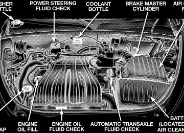
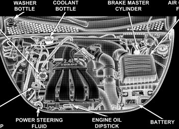
Adding Washer Fluid The fluid reservoir for the windshield washers and the rear window washer is shared. It is located in the rear of the engine compartment on the passenger side and should be checked for fluid level at regular intervals. Fill the reservoir with windshield washer solvent (not radia- tor antifreeze) and operate the system for a few seconds to flush out the residual water.
Washer Fluid Reservoir
STARTING AND OPERATING
CONTENTS
䡵 Starting Procedures . . . . . . . . . . . . . . . . . . . . . 196
▫ Automatic Transaxle . . . . . . . . . . . . . . . . . . . 196
▫ Manual Transaxle . . . . . . . . . . . . . . . . . . . . . 196
▫ Normal Starting . . . . . . . . . . . . . . . . . . . . . . 196
▫ Extremely Cold Weather (Below ⫺20°FOr ⫺29°C)
. . . . . . . . . . . . . . . . . . . . . . . . . . 197
▫ If Engine Fails To Start . . . . . . . . . . . . . . . . . 197
▫ After Starting . . . . . . . . . . . . . . . . . . . . . . . . 198
▫ Turbocharger “Cool Down” . . . . . . . . . . . . . . 198䡵 Automatic Transaxle — If Equipped . . . . . . . . . 199
▫ Brake/Transmission Interlock System . . . . . . . 200
▫ Automatic Transaxle Ignition InterlockSystem . . . . . . . . . . . . . . . . . . . . . . . . . . . . . 200
▫ Four Speed Automatic Transaxle . . . . . . . . . . 200
▫ Reset Mode . . . . . . . . . . . . . . . . . . . . . . . . . 201
▫ Gear Ranges For Four Speed AutomaticTransaxle . . . . . . . . . . . . . . . . . . . . . . . . . . . 201
䡵 AutoStick — If Equipped . . . . . . . . . . . . . . . . . 204
▫ AutoStick Operation . . . . . . . . . . . . . . . . . . . 204194 STARTING AND OPERATING
▫ AutoStick General Information . . . . . . . . . . . . 204
䡵 Manual Transaxle Operation . . . . . . . . . . . . . . . 205
▫ 2.4 Liter Turbo— If Equipped . . . . . . . . . . . . . 207
▫ Recommended Shift Speeds . . . . . . . . . . . . . . 207
▫ Downshifting . . . . . . . . . . . . . . . . . . . . . . . . 208
䡵 Parking Brake . . . . . . . . . . . . . . . . . . . . . . . . . 209
䡵 Brake System . . . . . . . . . . . . . . . . . . . . . . . . . . 211▫ Anti-Lock Brake System (ABS)
If Equipped . . . . . . . . . . . . . . . . . . . . . . . . . 212
䡵 Power Assisted Steering . . . . . . . . . . . . . . . . . . 213
䡵 Traction Control — If Equipped . . . . . . . . . . . . 214
䡵 Tire Safety Information . . . . . . . . . . . . . . . . . . . 216
▫ Tire Markings . . . . . . . . . . . . . . . . . . . . . . . . 216▫ Tire Identification Number (TIN) . . . . . . . . . . 219
▫ Tire Loading And Tire Pressure . . . . . . . . . . . 220
䡵 Tires—General Information . . . . . . . . . . . . . . . . 224
▫ Tire Pressure . . . . . . . . . . . . . . . . . . . . . . . . . 224
▫ Tire Inflation Pressures . . . . . . . . . . . . . . . . . 225
▫ Radial-Ply Tires . . . . . . . . . . . . . . . . . . . . . . 228
▫ Compact Spare Tire — If Equipped . . . . . . . . . 228
▫ Limited Use Spare — If Equipped . . . . . . . . . 229
▫ Tire Spinning . . . . . . . . . . . . . . . . . . . . . . . . 230
▫ Tread Wear Indicators . . . . . . . . . . . . . . . . . . 231
▫ Replacement Tires . . . . . . . . . . . . . . . . . . . . . 231
▫ Alignment And Balance . . . . . . . . . . . . . . . . . 232
䡵 Tire Chains . . . . . . . . . . . . . . . . . . . . . . . . . . . 233䡵 Snow Tires . . . . . . . . . . . . . . . . . . . . . . . . . . . 233
䡵 Tire Rotation Recommendations . . . . . . . . . . . . 234
䡵 Fuel Requirements . . . . . . . . . . . . . . . . . . . . . . 235▫ 2.4L Standard Engine And 2.4L Standard Turbo
Engine . . . . . . . . . . . . . . . . . . . . . . . . . . . . . 235
▫ 2.4L High Output Turbo Engine . . . . . . . . . . . 235
▫ Reformulated Gasoline . . . . . . . . . . . . . . . . . 236
▫ Gasoline/Oxygenate Blends . . . . . . . . . . . . . . 236
▫ MMT In Gasoline . . . . . . . . . . . . . . . . . . . . . 237STARTING AND OPERATING 195
䡵 Adding Fuel
▫ Materials Added To Fuel . . . . . . . . . . . . . . . . 237
▫ Fuel System Cautions . . . . . . . . . . . . . . . . . . 237
▫ Carbon Monoxide Warnings . . . . . . . . . . . . . . 238
. . . . . . . . . . . . . . . . . . . . . . . . . . 239
. . . . . . . . . . . . . . . 239
䡵 Vehicle Loading . . . . . . . . . . . . . . . . . . . . . . . . 241
䡵 Trailer Towing . . . . . . . . . . . . . . . . . . . . . . . . . 241
▫ Warranty . . . . . . . . . . . . . . . . . . . . . . . . . . . 242▫ Fuel Filler Cap (Gas Cap)
196 STARTING AND OPERATING
STARTING PROCEDURES Before starting your vehicle, adjust your seat, adjust both inside and outside mirrors, and fasten your seat belts.
CAUTION!
Long periods of engine idling, especially at high engine speeds can cause excessive exhaust tempera- tures which can damage your vehicle. Do not leave your vehicle unattended with the engine running.
WARNING!
Do not leave children or animals inside parked vehicles in hot weather. Interior heat build up may cause serious injury or death.
Automatic Transaxle The gear selector must be in the NEUTRAL or PARK position before you can start the engine. Apply the brakes before shifting to any driving gear. NOTE: You must press the brake pedal before shifting out of Park. Manual Transaxle Before starting the engine fully apply the parking brake, press the clutch pedal to the floor and place the gear selector in NEUTRAL. NOTE: The engine will not start unless the clutch pedal is pressed to the floor. Normal Starting Normal Starting of either a cold or a warm engine does not require pumping or depressing the accelerator pedal. Simply turn the ignition switch to the “START’” position and release when the engine starts. If the engine has not
started within 3 seconds, slightly depress the accelerator pedal while continuing to crank. If the engine fails to start within 15 seconds, turn the ignition switch to the “OFF” position, wait 10 to 15 seconds, then repeat the normal starting procedure.
WARNING!
Do not attempt to push or tow your vehicle to get it started. Vehicles equipped with an automatic trans- axle cannot be started this way. Unburned fuel could enter the catalytic converter and once the engine has started, ignite and damage the converter and vehicle. If the vehicle has a discharged battery, booster cables may be used to obtain a start from another vehicle. This type of start can be dangerous if done improp- erly, so follow the procedure carefully. See section 6
of this manual for jump starting instructions.STARTING AND OPERATING 197
Extremely Cold Weather (below ⫺20°F or ⫺29°C) To insure reliable starting at these temperatures, use of an externally powered electric engine block heater (available from your dealer) is recommended. If Engine Fails to Start If the engine fails to start after you have followed the “NORMAL STARTING” procedure, it may be flooded. Push the accelerator pedal all the way to the floor and hold it there. Crank the engine for no more than 15
seconds. This should clear any excess fuel in case the engine is flooded. Leave the ignition key in the ON position, release the accelerator pedal and repeat the “NORMAL STARTING” procedure.198 STARTING AND OPERATING
WARNING!
Never pour fuel or other flammable liquid into the throttle body air inlet opening in an attempt to start the vehicle. This could result in flash fire causing serious personal injury.
CAUTION!
To prevent damage to the starter, do not crank the engine for more than 15 seconds at a time. Wait 10 to 15 seconds before trying again.
After Starting The idle speed will automatically decrease as the engine warms up. Turbocharger “Cool Down”
NOTE: Letting the engine idle after severe operation allows the turbine housing to cool to normal operating temperature. The following chart should be used as a guide in deter- minning the amount of engine idle time required to sufficiently cool down the turbocharger before shut down, depending upon the type of driving and the amount of cargo.
TURBOCHARGER ⴖCOOL DOWNⴖ CHART
Driving Conditions
Normal Driving
Idle Time (in minutes) Before Shut Down
Not required.
STARTING AND OPERATING 199
Aggressive Driving or Heavily Loaded
Trailer Tow
AUTOMATIC TRANSAXLE — IF EQUIPPED
CAUTION!
Damage to the transaxle may occur if the following precautions are not observed: • Shift into PARK only after the vehicle has come to a
complete stop.
• Shift into or out of REVERSE only after the vehicle has come to a complete stop and the engine is at idle speed. • Do not shift from REVERSE, PARK, or NEUTRAL into any forward gear when the engine is above idle speed. • Before shifting into any gear, make sure your foot is
firmly on the brake pedal.
NOTE: You MUST press and hold the brake pedal down while shifting out of Park.
200 STARTING AND OPERATING
WARNING!
It is dangerous to shift the selector lever out of “P” or “N” if the engine speed is higher than idle speed. If your foot is not firmly on the brake pedal, the vehicle could accelerate quickly forward or in re- verse. You could lose control of the vehicle and hit someone or something. Only shift into gear when the engine is idling normally and when your right foot is firmly on the brake pedal.
Brake/Transmission Interlock System This system prevents you from moving the gear shift out of Park and into any gear unless the brake pedal is pressed. This system is active only while the ignition switch is in the ON positions. Always depress the brake pedal first, before moving the gear selector out of PARK.
Automatic Transaxle Ignition Interlock System This system prevents the key from being removed unless the shift lever is in PARK and the shift knob push button is out. It also prevents shifting out of PARK unless the key is in the OFF or ON positions. If a malfunction occurs, the system will trap the NOTE: key in the ignition cylinder to warn you that this safety feature is inoperable. The engine can be started and stopped but the key cannot be removed until you obtain service. Four Speed Automatic Transaxle The electronically controlled transaxle provides a precise shift schedule. The transaxle electronics are self calibrat- ing; therefore, the first few shifts on a new vehicle may be somewhat abrupt. This is a normal condition, and preci- sion shifts will develop within a few shift cycles.
Reset Mode The transaxle is monitored electronically for abnormal conditions. If a condition is detected that could cause damage, the transaxle shifts automatically into second gear. The transaxle remains in second gear despite the forward gear selected. Park (P), Reverse (R), and Neutral (N) will continue to operate. This second gear limp-in feature allows the vehicle to be driven to a dealer for service without damaging the transaxle. In the event that the problem has been momentary, the transaxle can be reset to regain all forward gears. Stop the vehicle and shift into Park (P). Turn the Key to OFF then restart the engine. Shift into D and resume driving.
STARTING AND OPERATING 201
NOTE: Even if the transaxle can be reset, it is recom- mended that you visit a dealer at your earliest possible convenience. Your dealer has diagnostic equipment to determine if the problem could recur. If the transaxle cannot be reset, dealer service is required. Gear Ranges For Four Speed Automatic Transaxle DO NOT race the engine when shifting from PARK or NEUTRAL positions into another gear range. “P” Park Supplements the parking brake by locking the transmis- sion. The engine can be started in this range. Never use P (Park) while the vehicle is in motion. Apply the parking brake when leaving the vehicle in this range. Always apply the parking brake first, and then place the selector in P (Park) position.
202 STARTING AND OPERATING
WARNING!
Unintended movement of a vehicle could injure those in and near the vehicle. As with all vehicles, you should never exit a vehicle while the engine is running. Before exiting a vehicle, you should always shift the vehicle into P (Park), remove the key from the ignition, and apply the parking brake. Once the key is removed from the ignition, the transmission shift lever is locked in the P (Park) position, securing the vehicle against unwanted movement. Further- more, you should never leave children unattended inside a vehicle.
The following indicators should be used to ensure that you have engaged the transmission shift lever into the P (Park) position:
• When shifting into P (Park), depress the button on the shift lever and firmly move the lever all the way forward until it stops. • Look at the shift indicator window on the console to • When engaged in P (Park), you will not be able to move the shifter rearward without depressing the shift lever button.
ensure it is in the P (Park) position.
CAUTION!
Before moving the shift lever out of P (Park), you must turn the ignition from LOCK to ON so the steering wheel and shift lever are released. Other- wise, damage to the steering column or shifter could result.
“R” Reverse Shift into this range only after the vehicle has come to a complete stop. “N” Neutral Engine may be started in this range. “D” Overdrive This range should be used for most city and highway driving. It provides smoothest up shifts and down shifts and best fuel economy. When frequent transaxle shifting occurs while using the Overdrive range, such as when operating the vehicle under heavy loading conditions (in hilly terrain, travel- ing into strong head winds, or while towing trailers), use the “3” range.
STARTING AND OPERATING 203
“3” Drive This range eliminates shifts into Overdrive. The transaxle will operate normally in first and second while in this range. NOTE: Using the “3” range while operating the vehicle under heavy operating conditions will improve perfor- mance, fuel economy, and extend transaxle life by reduc- ing excessive shifting and heat build up. Use the “3” range when descending steep grades to prevent brake system distress. “1” Low This range should be used for maximum engine braking when descending steep grades. In this range, up shifts will occur only to prevent engine over speed while down shifts from 2nd to first will occur as early as possible.
204 STARTING AND OPERATING
AUTOSTICK — IF EQUIPPED Autostick is a driver-interactive transmission that offers manual gear shifting capability to provide you with more control. Autostick allows you to maximize engine brak- ing, eliminate undesirable upshifts and downshifts, and improve overall vehicle performance. This system can also provide you with more control during passing, city driving, cold slippery conditions, mountain driving, trailer towing, and many other situations. Autostick Operation The Autostick position is just below the Overdrive posi- tion and is identified by the word “AUTOSTICK”. When you place the shift lever in the Autostick position, it can be moved from side to side. Moving the lever to the left (-) triggers a downshift and to the right (+) an upshift. The gear position will be shown in the transmission gear display, located in the instrument cluster.
You can shift in or out of the autostick mode at any time without taking your foot off the accelerator pedal. If you choose the Overdrive mode, the transmission will oper- ate automatically; shifting between the four available gears. When you wish to engage autostick, simply move the shift lever to the AUTOSTICK position. The transmis- sion will remain in the current gear until an upshift or downshift is chosen. Move the lever back to the Overdrive position to shift out of the Autostick mode. Autostick General Information • The transmission will automatically upshift from first to second gear and from second to third gear when engine speed reaches about 6300 RPM.
• Downshifts from third to second gear above 74 mph (119 km/h) and from second to first gear above 41
mph (66 km/h) will be ignored. • You can start out in first, second, or third gear. Shifting into fourth gear can occur only after vehicle speed reaches 15 mph (24 km/h). • The transmission will automatically downshift to first • Starting out in third gear is helpful in snowy or icy • While in the Autostick mode, Speed Control will onlygear when coming to a stop.
conditions.
function in third or fourth gear.
STARTING AND OPERATING 205
Downshifting out of third gear will turn off the speed control.
• If the system detects powertrain overheating,
the transmission will revert to the automatic shift mode and remain in that mode until the powertrain cools off. • If the system detects a problem it will disable the Autostick mode and the transmission will return to the automatic mode until the problem is corrected.
MANUAL TRANSAXLE OPERATION
NOTE: The parking brake should be engaged and the gear selector placed in REVERSE before leaving the vehicle, especially on an incline.
206 STARTING AND OPERATING
Fully depress the clutch pedal before you shift gears. As you release the clutch pedal, lightly depress the accelera- tor pedal.
Use each gear in numerical order - do not skip a gear. Be sure the transaxle is in FIRST gear, (not THIRD), when starting from a standing position. Damage to the clutch can result from starting in THIRD.
For most city driving you will find it easier to use only the lower gears. For steady highway driving with light accelerations, 5th gear is recommended. Never drive with your foot resting on the clutch pedal, or try to hold the vehicle on a hill with the clutch pedal partially engaged. This will cause abnormal wear on the clutch. Never shift into REVERSE until the vehicle has come to a complete stop. NOTE: During cold weather, until the transaxle lubri- cant is warm, you may experience slightly higher shift efforts. This is normal and not harmful to the transaxle.
2.4 Liter Turbo— If Equipped
The neutral position of the shift lever is located between THIRD and FOURTH gear. This is the position the shifter lever will return to automatically when neutral is se- lected. When shifting into FIFTH gear, be sure to press
STARTING AND OPERATING 207
the shifter lever all the way to the right to avoid acciden- tally selecting THIRD gear. Also, use care when selecting FIRST gear to avoid accidentally selecting REVERSE. When moving the shifter lever into REVERSE press the lever to the left until the resistance is overcome. When the ignition switch is in the ON position, a chime will sound to confirm that reverse has been selected and the backup lights will illuminate. NOTE: Listen for the audible chime to confirm RE- VERSE gear is properly selected. Never shift into RE- VERSE until the vehicle has come to a complete stop. Recommended Shift Speeds To use your manual transaxle for optimal fuel economy, it should be upshifted as listed in table 1.
208 STARTING AND OPERATING
TABLE 1-MANUAL TRANSAXLE NORMAL AC-
CELERATION AND CRUISE SHIFT SPEEDS
TABLE 2-MANUAL TRANSAXLE MAXIMUM PER-
FORMANCE SHIFT SPEEDS
IN mph (km/h)
MODE 1 to 2
2 to 3
3 to 4
4 to 5
Accel Cruise Accel Cruise
15 (24) 15 (24) 15 (24) 16 (26)
25 (40) 25 (40) 25 (40) 20 (32)
40 (65) 42 (68) 33 (53) 28 (45)
45 (72) 45 (72) 44 (70) 38 (61)
EN- GINE SIZE 2.4L Turbo 2.4L Non- Turbo
For improved performance, your manual transaxle may be upshifted up to the maximum speeds listed in table 2
(within legal speed limits).ENGINE
SIZE
2.4L
IN mph (km/h)
1 to 2
2 to 3
3 to 4
4 to 5
30
(48)60
(97)85
(136)115
(185)If you exceed these speeds, you may notice the engine cut in and out. This is caused by an electronic limiter in the engine computer. The engine will run normally when you reduce engine speed. Downshifting Proper downshifting will improve fuel economy and prolong engine life.
CAUTION!
If you skip more than one gear while downshifting or downshift at too high an engine speed, you could damage the engine, transmission, or clutch.
To maintain a safe speed and prolong brake life, shift down to 2nd or 1st when descending a steep grade. When turning a corner, or driving up a steep grade, downshift early so that the engine will not be overbur- dened.
PARKING BRAKE
When the parking brake is applied with the ignition on, the Brake Light in the instrument cluster will come on.
STARTING AND OPERATING 209
NOTE: This light only shows that the parking brake is on. It does not show the degree of brake application. If the parking brake is applied while the vehicle is moving, a chime will sound to alert the driver. The chime will sound up to 10 times or until the vehicle has returned to a stop. Before leaving the vehicle, make sure that the parking brake is set. To set the parking brake, pull up firmly on the lever. Also place the gear selector in the Park position (automatic transaxle) or Reverse (manual transaxle). To release the parking brake, apply the brake pedal, pull up slightly on the lever, then depress the button on the end of the lever and push the lever fully down toward the floor.
210 STARTING AND OPERATING
NOTE: The parking brake lever will not release unless the lever is pulled up slightly past its applied position.
When parking on a hill, it is important to set the parking brake before placing the gear selector in Park, otherwise the load on the automatic transaxle locking mechanism may make it difficult to move the selector out of Park. As an added precaution, turn the front wheels toward the curb on a downhill grade and away from the curb on a uphill grade. You should always apply the parking brake before leav- ing the vehicle.
Parking Brake Lever
WARNING!
• Leaving children in a vehicle unattended is dan- gerous for a number of reasons. A child or others could be injured. Children should be warned not to touch the parking brake or the gear selector. Don’t leave the keys in the ignition. A child could operate power windows, other controls, or move the vehicle. • Be sure the parking brake is fully disengaged before driving; failure to do so can lead to brake failure and an accident.
STARTING AND OPERATING 211
BRAKE SYSTEM Your vehicle is equipped with power assisted brakes as standard equipment. In the event power assist is lost for any reason (for example, repeated brake applications with the engine off), the brakes will still function. How- ever, the effort required to brake the vehicle will be much greater than that required with the power system oper- ating.
WARNING!
Riding the brakes can lead to brake failure and possibly an accident. Driving with your foot resting or riding on the brake pedal can result in abnormally high brake temperatures, excessive lining wear, and possible brake damage. You wouldn’t have your full braking capacity in an emergency.
During stops where ABS is activated, a vibration of the brake pedal may be felt and associated system noises may be heard. NOTE: Pumping of the brake pedal will diminish the effectiveness of Anti-lock brakes and may lead to an accident. Pumping makes the stopping distance longer. Just press firmly on your brake pedal when you need to slow down or stop.
212 STARTING AND OPERATING
If either of the two hydraulic systems lose normal capa- bility, the remaining system will still function with some loss of overall braking effectiveness. This will be evident by increased pedal travel during application and greater pedal force required to slow or stop. In addition, if the malfunction is caused by an internal leak, as the brake fluid in the master cylinder drops, the brake warning indicator will light. Anti-Lock Brake System (ABS) — If Equipped The ABS gives increased vehicle stability and brake performance under most braking conditions. The system automatically “pumps” the brakes during severe braking conditions to prevent wheel lock up. All vehicle wheels and tires must be the same size and tires must be properly inflated to produce accurate signals for the computer. However, the system will compensate when the compact spare is in use.
STARTING AND OPERATING 213
POWER ASSISTED STEERING The power assisted steering system of your vehicle provides mechanical steering capability in the event power assist is lost. If for some reason the hydraulic pressure is interrupted, it will still be possible to steer your vehicle. Under these conditions you will observe a substantial increase in steering effort.
WARNING!
• Anti-lock system (ABS) cannot prevent the natu- ral laws of physics from acting on the vehicle, nor can it increase braking or steering efficiency be- yond that afforded by the condition of the vehicle brakes and tires or the traction afforded.
• The ABS cannot prevent accidents,
including those resulting from excessive speed in turns, following another vehicle too closely, or hydro- planing. Only a safe, attentive, and skillful driver can prevent accidents. • The capabilities of an ABS equipped vehicle must never be exploited in a reckless or dangerous manner which could jeopardize the user’s safety or the safety of others.
214 STARTING AND OPERATING
TRACTION CONTROL — IF EQUIPPED The Traction Control System will improve acceleration and steering on slippery surfaces by reducing tire spin. The system reduces wheel slip and maintains traction at the driving (front) wheels by engaging the brake on the wheel that is losing traction. When this occurs the TRAC indicator light located above the instrument cluster odometer will flash. The system operates at speeds below 40 mph (64 km/h).
Traction Control Switch
A push-button at the center of the instrument panel, below the radio, turns the Traction Control System ON or OFF.
system off;
The system is always in the “ON” mode unless: • The TRAC OFF switch has been used to turn the • There is a Anti-Lock Brake System malfunction; • There is a Traction Control System malfunction; • The system has been automatically deactivated to prevent damage to the brake system due to overheated brake temperatures.
NOTE: Extended heavy use of Traction Control may cause the system to deactivate and turn on the TRAC OFF Light located in the instrument cluster.
STARTING AND OPERATING 215
This is to prevent overheating of the brake system and is a normal condition. The system will remain disabled for about 4 minutes until the brakes have cooled. The system will automatically reactivate and turn off the TRAC OFF light. If your vehicle becomes stuck in mud, ice, or snow, turn the Traction Control System Off before attempting to “rock” the vehicle free.
216 STARTING AND OPERATING
TIRE SAFETY INFORMATION
Tire Markings
NOTE: • P(Passenger)-Metric tire sizing is based on U.S. design standards. P-Metric tires have the letter “P” molded into the sidewall preceding the size designation. Ex- ample: P215/65R15 95H.
• European Metric tire sizing is based on European design standards. Tires designed to this standard have the tire size molded into the sidewall beginning with the section width. The letter ⬙P⬙ is absent from this tire size designation. Example: 215/65R15 96H • LT(Light Truck)-Metric tire sizing is based on U.S. design standards. The size designation for LT-Metric tires is the same as for P-Metric tires except for the letters “LT” that are molded into the sidewall preced- ing the size designation. Example: LT235/85R16. • Temporary Spare tires are high pressure compact spares designed for temporary emergency use only. Tires designed to this standard have the letter “T” molded into the sidewall preceding the size designa- tion. Example: T145/80D18 103M. • High Flotation tire sizing is based on U.S. design standards and begins with the tire diameter molded into the sidewall. Example: 31x10.5 R15 LT.
Tire Sizing Chart
Size Designation:
EXAMPLE:
P = Passenger car tire size based on U.S. design standards ⴖ....blank....ⴖ = Passenger car tire based on European design standards LT = Light Truck tire based on U.S. design standards T = Temporary Spare tire 31 = Overall Diameter in Inches (in) 215 = Section Width in Milimeters (mm) 65 = Aspect Ratio in Percent (%)
—Ratio of section height to section width of tire.
10.5 = Section Width in Inches (in) R = Construction Code
—⬙R⬙ means Radial Construction. —⬙D⬙ means Diagonal or Bias Construction.
15 = Rim Diameter in Inches (in)
STARTING AND OPERATING 217
218 STARTING AND OPERATING
Service Description:
95 = Load Index
EXAMPLE:
—A numerical code associated with the maximum load a tire can carry.
H = Speed Symbol
—A symbol indicating the range of speeds at which a tire can carry a load corresponding to its load index under certain operating conditions. —The maximum speed corresponding to the Speed Symbol should only be achieved un- der specified operating conditions. (ie. tire pressure, vehicle loading, road conditions and posted speed limits).
Load Identification:
ⴖ....blank....ⴖ = Absence of any text on sidewall of the tire indicates a Standard Load (SL) Tire Extra Load (XL) = Extra Load (or Reinforced) Tire Light Load = Light Load Tire C,D,E = Load range associated with the maximum load a tire can carry at a specified pressure
Maximum Load — Maximum Load indicates the maximum load this tire is designed to carry. Maximum Pressure — Maximum Pressure indicates the maximum permissible cold tire inflation pressure for this tire.
Tire Identification Number (TIN) The TIN may be found on one or both sides of the tire however the date code may only be on one side. Tires with white sidewalls will have the full TIN including date code located on the white sidewall side of the tire.
STARTING AND OPERATING 219
Look for the TIN on the outboard side of black sidewall tires as mounted on the vehicle. If the TIN is not found on the outboard side then you will find it on the inboard side of the tire.
DOT = Department of Transportation
—This symbol certifies that the tire is in compliance with the U.S. Department of Transportation tire safety standards, and is approved for highway use.
EXAMPLE:
DOT MA L9 ABCD 0301
MA = Code representing the tire manufacturing location.(2 digits) L9 = Code representing the tire size.(2 digits) ABCD = Code used by tire manufacturer.(1 to 4 digits) 03 = Number representing the week in which the tire was manufactured.(2 digits)
—03 means the 3rd week.
01 = Number representing the year in which the tire was manufactured.(2 digits)
—01 means the year 2001. —Prior to July 2000, tire manufacturers were only required to have 1 number to represent the year in which the tire was manufactured. Example: 031 could represent the 3rd week of 1981 or 1991.
220 STARTING AND OPERATING
Tire Loading and Tire Pressure
Tire Placard Location NOTE: The proper cold tire inflation pressure for pas- senger cars is listed on either the face of the driver’s door or the driver’s side “B” pillar. For vehicles other than passenger cars, the cold tire inflation pressures are listed on either the “B” pillar, the Certification Label or in the Tire Inflation Pressures brochure in the glove compart- ment.
Tire Placard Location
Tire and Loading Information Placard
Tire and Loading Information
This placard tells you important information about the: 1) number of people that can be carried in the vehicle 2) the total weight your vehicle can carry 3) the tire size designed for your vehicle
STARTING AND OPERATING 221
4) the cold tire inflation pressures for the front, rear and spare tires. Loading The vehicle maximum load on the tire must not exceed the load carrying capacity of the tire on your vehicle. You will not exceed the tire’s load carrying capacity if you adhere to the loading conditions, tire size and cold tire inflation pressures specified on the Tire and Loading Information placard and the Vehicle Loading section of this manual. NOTE: Under a maximum loaded vehicle condition, gross axle weight ratings (GAWR’s) for the front and rear axles must not be exceeded. For further information on GAWR’s, vehicle loading and trailer towing, see the Vehicle Loading section of this manual. To determine the maximum loading conditions of your vehicle, locate the statement “The combined weight of occupants and cargo should never exceed XXX kg or XXX
222 STARTING AND OPERATING
lbs.” on the Tire and Loading Information placard. The combined weight of occupants, cargo/luggage and trailer tongue weight (if applicable) should never exceed the weight referenced here. Steps for Determining Correct Load Limit 1. Locate the statement “The combined weight of occu- pants and cargo should never exceed XXX pounds” on your vehicle’s placard. 2. Determine the combined weight of the driver and passengers that will be riding in your vehicle. 3. Subtract the combined weight of the driver and pas- sengers from XXX kilograms or XXX pounds. 4. The resulting figure equals the available amount of cargo and luggage load capacity. For example, if “XXX” amount equals 1400 lbs. and there will be five 150 lb. passengers in your vehicle, the amount of available cargo and luggage load capacity is 650 lb. (since 5 x 150 = 750, and 1400 – 750 = 650 lb.)
5. Determine the combined weight of luggage and cargo being loaded on the vehicle. That weight may not safely exceed the available cargo and luggage load capacity calculated in step 4. 6. If your vehicle will be towing a trailer, load from your trailer will be transferred to your vehicle. Consult this manual to determine how this reduces the available cargo and luggage load capacity of your vehicle. NOTE: The following table shows examples on how to calculate total load, cargo/luggage and towing capacities of your vehicle with varying seating configurations and number and size of occupants. This table is for illustra- tion purposes only and may not be accurate for the seating and load carry capacity of your vehicle. NOTE: For the following example the combined weight of occupants and cargo should never exceed 865 lbs. (392
Kg).STARTING AND OPERATING 223
224 STARTING AND OPERATING
WARNING!
1. Safety—
Overloading of your tires is dangerous. Overloading can cause tire failure, affect vehicle handling, and increase your stopping distance. Use tires of the recommended load capacity for your vehicle. Never overload them.
TIRES—GENERAL INFORMATION
Tire Pressure Proper tire inflation pressure is essential to the safe and satisfactory operation of your vehicle. Three primary areas are affected by improper tire pressure:
WARNING!
Improperly inflated tires are dangerous and can cause accidents. • Under inflation increases tire flexing and can result in tire failure. • Over inflation reduces a tire’s ability to cushion shock. Objects on the road and chuck holes can cause damage that results in tire failure. • Unequal tire pressures can cause steering problems. You could lose control of your vehicle. • Over inflated or under inflated tires can affect vehicle handling and can fail suddenly, resulting in loss of vehicle control. • Unequal tire pressures from one side of the vehicle to the other can cause the vehicle to drift to the right or left. Always drive with each tire inflated to the recom- mended cold tire inflation pressure.
2. Economy— Improper inflation pressures can cause uneven wear patterns to develop across the tire tread. These abnormal wear patterns will reduce tread life resulting in a need for earlier tire replacement. Underinflation also increases tire rolling resistance and results in higher fuel consumption. 3. Ride Comfort and Vehicle Stability— Proper tire inflation contributes to a comfortable ride. Overinflation produces a jarring and uncomfortable ride. Tire Inflation Pressures The proper cold tire inflation pressure for passenger cars is listed on either the face of the driver’s door or the driver’s side “B” pillar. For vehicles other than passenger cars, the cold tire inflation pressures are listed on either the “B” pillar, the Certification Label or in the Tire Inflation Pressures brochure in the glove compartment.
STARTING AND OPERATING 225
Some vehicles may have Supplemental Tire Pressure Information for vehicle loads that are less than the maximum loaded vehicle condition. These pressure con- ditions will be found in the “Supplemental Tire Pressure Information” section of this manual.
Tire Placard Location
226 STARTING AND OPERATING
The pressure should be checked and adjusted as well as inspecting for signs of tire wear or visible damage at least once a month. Use a good quality pocket-type gauge to check tire pressure. Do not make a visual judgement when determining proper inflation. Radial tires may look properly inflated even when they are under inflated.
CAUTION!
After inspecting or adjusting the tire pressure al- ways reinstall the valve stem cap–if equipped. This will prevent moisture and dirt from entering the valve stem, which could damage the valve stem.
Inflation pressures specified on the placard are always “cold tire inflation pressure”. Cold tire inflation pressure is defined as the tire pressure after the vehicle has not been driven for at least 3 hours, or driven less than 1mile
(1 km) after a 3 hour period. The cold tire inflation pressure must not exceed the maximum inflation pres- sure molded into the tire side wall. Check tire pressures more often if subject to a wide range of outdoor temperatures, as tire pressures vary with