- Download PDF Manual
-
Vehicles equipped with power driver or passenger seats may be also be equipped with power lumbar. The power lumbar switch is located on the outboard side of the power seat. Push the switch forward or rearward to increase or decrease the lumbar support. Push the switch upward or downward to raise or lower the lumbar support.
Heated Seats — If Equipped On some models, the front and rear seats may be equipped with heaters in both the seat cushions and seatbacks. The front driver and passenger heated seats are operated using the Uconnect Touch™ System.
WARNING!
• Persons who are unable to feel pain to the skin because of advanced age, chronic illness, diabetes, spinal cord injury, medication, alcohol use, ex- haustion or other physical condition must exercise care when using the seat heater. It may cause burns even at low temperatures, especially if used for long periods of time.
(Continued)
Power Lumbar Switch
WARNING! (Continued)
• Do not place anything on the seat that insulates against heat, such as a blanket or cushion. This may cause the seat heater to overheat. Sitting in a seat that has been overheated could cause serious burns due to the increased surface temperature of the seat.
UNDERSTANDING THE FEATURES OF YOUR VEHICLE 161
Front Heated Seat Operations — Uconnect Touch™ 8.4 and 8.4 Nav: Press the “Controls” soft-key located on the bottom of the Uconnect Touch™ display.Controls Soft-Key
162 UNDERSTANDING THE FEATURES OF YOUR VEHICLE
Press the “Driver” or “Passenger” seat soft-key once to select HI-level heating. Press the soft- key a second time to select LO-level heating. Press the soft-key a third time to shut the
heating elements OFF.
Heated Seats Soft-Keys
NOTE: Once a heat setting is selected, heat will be felt within two to five minutes. When the HI-level setting is selected, the heater will provide a boosted heat level during the first four minutes of operation. Then, the heat output will drop to the normal HI-level. If the HI-level setting is selected, the system will automatically switch to LO-level after a maximum of 60 minutes of continuous operation. At that time, the display will change from HI to LO, indicating the change. The LO-level setting will turn OFF automati- cally after a maximum of 45 minutes. Vehicle Equipped With Remote Start On models that are equipped with remote start, the driver’s heated seat can be programmed to come on during a remote start. Refer to “Remote Starting System — If Equipped” in “Things To Know Before Starting Your Vehicle” for further information.
Rear Heated Seats On some models, the two outboard seats are equipped with heated seats. The heated seat switches for these seats are located on the rear of the center console. There are two heated seat switches that allow the rear passen- gers to operate the seats independently. You can choose from HI, LO or OFF heat settings. Amber indicator lights in each switch indicate the level of heat in use. Two indicator lights will illuminate for HI, one for LO and none for OFF.
Press the switch once to select HI-level heating. Press the switch a second time to select LO- level heating. Press the switch a third time to shut the heating elements OFF.
NOTE: • Once a heat setting is selected, heat will be felt within • The engine must be running for the heated seats to
two to five minutes.
operate.
UNDERSTANDING THE FEATURES OF YOUR VEHICLE 163
When the HI-level setting is selected, the heater will provide a boosted heat level during the first four minutes of operation. Then, the heat output will drop to the normal HI-level. If the HI-level setting is selected, the system will automatically switch to LO-level after a maximum of 60 minutes of continuous operation. At that time, the number of illuminated LEDs changes from two to one, indicating the change. The LO-level setting will turn OFF automatically after a maximum of 45 minutes. Ventilated Seats — If Equipped On some models, both the driver and passenger seats are ventilated. Located in the seat cushion and seatback are small fans that draw air from the seat surface through fine perforations in the seat cover to help keep the driver and front passenger cooler in higher ambient temperatures. The ventilated seats can be operated using the Uconnect Touch™ System.164 UNDERSTANDING THE FEATURES OF YOUR VEHICLE Front Ventilated Seat Operation — Uconnect Touch™ 8.4/8.4 Nav: Press the “Controls” soft-key located on the bottom of the Uconnect Touch™ display.
time to select LO-level ventilation. Press the soft-key a third time to shut off the seat ventilation.
Controls Soft-Key
Press the “Driver” or “Passenger” seat soft-key once to select HI-level ventilation. Press the soft-key a second
Ventilated Seats Soft-Keys
NOTE: The engine must be running for the ventilated seats to operate.
Vehicles Equipped With Remote Start On models that are equipped with remote start, the driver’s ventilated seat can be programmed to come on during a remote start. Refer to “Remote Starting System — If Equipped” in “Things To Know Before Starting Your Vehicle” for further information. Head Restraints Head restraints are designed to reduce the risk of injury by restricting head movement in the event of a rear impact. Head restraints should be adjusted so that the top of the head restraint is located above the top of your ear.
UNDERSTANDING THE FEATURES OF YOUR VEHICLE 165
WARNING!
The head restraints for all occupants must be prop- erly adjusted prior to operating the vehicle or occu- pying a seat. Head restraints should never be ad- justed while the vehicle is in motion. Driving a vehicle with the head restraints improperly adjusted or removed could cause serious injury or death in the event of a collision.
166 UNDERSTANDING THE FEATURES OF YOUR VEHICLE Active Head Restraints — Front Seats The front driver and passenger seats are equipped with Active Head Restraints (AHR). In the event of a rear impact the AHRs will automatically extend forward minimizing the gap between the back of the occupants head and the AHR. The AHRs will automatically return to their normal position following a rear impact. If the AHRs do not return to their normal position see your authorized dealer immediately. To raise the head restraint, pull upward on the head restraint. To lower the head restraint, press the push button, located at the base of the head restraint, and push downward on the head restraint.
Push Button
NOTE: The head restraints should only be removed by qualified technicians, for service purposes only. If either of the head restraints require removal, see your autho- rized dealer.
WARNING!
Do not place items over the top of the Active Head Restraint, such as coats, seat covers or portable DVD players. These items may interfere with the operation of the Active Head Restraint in the event of a collision and could result in serious injury or death.
Rear Head Restraints The center head restraint has two positions, up or down. When the center seat is being occupied the head restraint should be in the raised position. When there are no occupants in the center seat the head restraint can be lowered for maximum visibility for the driver. To raise the head restraint, pull upward on the head restraint. To lower the head restraint, press the push button, located at the base of the head restraint, and push downward on the head restraint.
UNDERSTANDING THE FEATURES OF YOUR VEHICLE 167
Push Button
NOTE: The outboard head restraints are not adjustable. Refer to “Occupant Restraints” in “Things To Know Before Starting Your Vehicle” for tether routing.
168 UNDERSTANDING THE FEATURES OF YOUR VEHICLE Folding Rear Seat The rear seatbacks can be folded forward to provide an additional storage area. To fold the rear seatback, pull on the loops located on the upper seatback. NOTE: These loops can be tucked away when not in use.
After releasing the seatback, it can be folded forward.
Folded Rear Seatback
When the seatback is folded to the upright position, make sure it is latched by strongly pulling on the top of the seatback above the seat strap.
Rear Seatback Loop
WARNING!
• Be certain that the seatback is securely locked into position. If the seatback is not securely locked into position, the seat will not provide the proper stability for child seats and/or passengers. An improperly latched seat could cause serious injury. • The cargo area in the rear of the vehicle (with the rear seatbacks in the locked-up or folded down position) should not be used as a play area by children when the vehicle is in motion. They could be seriously injured in a collision. Children should be seated and using the proper restraint system.
UNDERSTANDING THE FEATURES OF YOUR VEHICLE 169
DRIVER MEMORY SEAT — IF EQUIPPED This feature allows the driver to store up to two different memory profiles for easy recall through a memory switch. Each memory profile contains desired position settings for the driver seat, side mirrors, adjustable pedals (if equipped), and power tilt and telescopic steer- ing column (if equipped) and a set of desired radio station presets. Your Remote Keyless Entry (RKE) trans- mitter can also be programmed to recall the same posi- tions when the UNLOCK button is pressed. NOTE: • Only one RKE transmitter can be linked to each of the • Passive Entry door handles cannot be linked to the memory function. Use either the memory recall switch or the RKE transmitter (if linked to the memory feature) to recall memory positions 1 or 2.
memory positions.
170 UNDERSTANDING THE FEATURES OF YOUR VEHICLE The memory seat switch is located on the driver’s door trim panel. The switch consists of three buttons: The (S) button, which is used to activate the memory save function and the (1) and (2) buttons which are used to recall either of two pre-programmed memory profiles.
Memory Seat Switch
Programming The Memory Feature To create a new memory profile, perform the following: 1. Place the ignition into the RUN position. 2. Adjust all memory profile settings to desired prefer- ences (i.e., seat, side mirror, adjustable pedals [if equipped], power tilt and telescopic steering column [if equipped], and radio station presets). 3. Press and release the S (Set) button on the memory switch. 4. Within five seconds, press and release either of the memory buttons (1) or (2). The Electronic Vehicle Infor- mation Center (EVIC) will display which memory posi- tion has been set. NOTE: • Memory profiles can be set without the vehicle in PARK, but the vehicle must be in PARK to recall a memory profile.
• The Recall Memory with Remote Key Unlock feature can be enabled through the Uconnect Touch™ System, refer to “Uconnect Touch™ Settings” in “Understand- ing Your Instrument Panel” for further information. Linking And Unlinking The Remote Keyless Entry Transmitter To Memory Your RKE transmitters can be programmed to recall one of two pre-programmed memory profiles by pressing the UNLOCK button on the RKE transmitter. To program your RKE transmitters, perform the follow- ing: 1. Remove the Key Fob from the ignition (or change the ignition to OFF, for vehicles equipped with Keyless Enter-N-Go). 2. Select desired memory profile (1) or (2). 3. Once the profile has been recalled, press and release the SET (S) button on the memory switch, then press and
UNDERSTANDING THE FEATURES OF YOUR VEHICLE 171
release button (1) or (2) accordingly. “Memory Profile Set” (1 or 2) will display in the instrument cluster on vehicles equipped with the EVIC. 4. Press and release the LOCK button on the RKE transmitter within 10 seconds. NOTE: Your RKE transmitters can be unlinked to your memory settings by pressing the SET (S) button followed by the UNLOCK button on the RKE transmitter in Step 4
above. Memory Position RecallNOTE: The vehicle must be in PARK to recall memory positions. If a recall is attempted when the vehicle is not in PARK, a message will display in the EVIC (if equipped). To recall the memory settings for driver one, press MEMORY button number (1) on the driver’s door or the UNLOCK button on the RKE transmitter linked to memory position 1.
172 UNDERSTANDING THE FEATURES OF YOUR VEHICLE To recall the memory setting for driver two, press MEMORY button number (2) on the driver’s door or the UNLOCK button on the RKE transmitter linked to memory position 2. A recall can be cancelled by pressing any of the MEMORY buttons (S, 1, or 2) on the driver’s door during a recall. When a recall is cancelled, the driver seat, side mirror, adjustable pedals (if equipped), and power tilt and telescopic steering column (if equipped) stop mov- ing. A delay of one second will occur before another recall can be selected. Easy Entry/Exit Seat (Available With Memory Seat Only) This feature provides automatic driver seat positioning to enhance driver mobility when entering and exiting the vehicle. The distance the driver seat moves depends on where you have the driver seat positioned when you remove the
Key Fob from the ignition (or change the ignition to OFF, for vehicles equipped with Keyless Enter-N-Go). • When you remove the Key Fob from the ignition (or change the ignition to OFF, for vehicles equipped with Keyless Enter-N-Go), the driver seat will move about 2.4 in (60 mm) rearward if the driver seat position is greater than or equal to 2.7 in (67.7 mm) forward of the rear stop. The seat will return to its previously set position when you place the ignition into the ACC or RUN position. • When you remove the Key Fob from the ignition (or change the ignition to OFF, for vehicles equipped with Keyless Enter-N-Go), the driver seat will move to a position 0.3 in (7.7 mm) forward of the rear stop if the driver seat position is between 0.9 in and 2.7 in (22.7 mm and 67.7 mm) forward of the rear stop. The seat will return to its previously set position when you place the ignition to the ACC or RUN position.
• The Easy Entry/Easy Exit feature is disabled when the driver seat position is less than 0.9 in (22.7 mm) forward of the rear stop. At this position, there is no benefit to the driver by moving the seat for Easy Exit or Easy Entry.
Each stored memory setting will have an associated Easy Entry and Easy Exit position. NOTE: The Easy Entry/Easy Exit feature can be en- abled or disabled using the Uconnect Touch™ System, refer to “Uconnect Touch™ Settings” in “Understanding Your Instrument Panel” for further information.
UNDERSTANDING THE FEATURES OF YOUR VEHICLE 173
TO OPEN AND CLOSE THE HOOD Two latches must be released to open the hood. 1. Pull the hood release lever located under the left side of the instrument panel.
Hood Release Lever
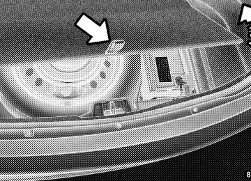
174 UNDERSTANDING THE FEATURES OF YOUR VEHICLE 2. Move to the outside of the vehicle and push the safety catch to the left. The safety catch is located under the center front edge of the hood.
Hood Safety Latch
Use the hood prop rod (if equipped) to secure the hood in the open position.
CAUTION!
To prevent possible damage, do not slam the hood to close it. Lower the hood, until it is open approxi- mately 6 in (15 cm), and then drop it. This should secure both latches. Never drive your vehicle unless the hood is fully closed, with both latches engaged.
WARNING!
Be sure the hood is fully latched before driving your vehicle. If the hood is not fully latched, it could open when the vehicle is in motion and block your vision. Failure to follow this warning could result in serious injury or death.
LIGHTS
Headlight Switch
The headlight switch is located on the left side of the instrument panel. This switch controls the operation of the headlights, parking lights, instru- ment panel lights, instrument panel light dimming, inte- rior lights and fog lights.
UNDERSTANDING THE FEATURES OF YOUR VEHICLE 175
Headlight Switch
Rotate the headlight switch clockwise to the first detent for parking light and instrument panel light operation. Rotate the headlight switch to the second detent for headlight, parking light and instrument panel light operation.
176 UNDERSTANDING THE FEATURES OF YOUR VEHICLE Automatic Headlights — If Equipped This system automatically turns the headlights on or off according to ambient light levels. To turn the system on, rotate the headlight switch counterclockwise to the AUTO position. When the system is on, the headlight time delay feature is also on. This means the headlights will stay on for up to 90 seconds after you place the ignition into the OFF position. To turn the automatic system off, move the headlight switch out of the AUTO position. NOTE: The engine must be running before the head- lights will come on in the automatic mode. Headlights On With Wipers (Available With Automatic Headlights Only) When this feature is active, the headlights will turn on approximately 10 seconds after the wipers are turned on if the headlight switch is placed in the AUTO position. In
addition, the headlights will turn off when the wipers are turned off if they were turned on by this feature. NOTE: The Headlights On with Wipers feature can be turned on or off using the Uconnect Touch™ System, refer to “Uconnect Touch™ Settings” in “Understanding Your Instrument Panel” for further information. Headlight Time Delay This feature provides the safety of headlight illumination for up to 90 seconds (programmable) when leaving your vehicle in an unlit area. To activate the delay feature, place the ignition in the OFF position while the headlights are still on. Then, turn off the headlights within 45 seconds. The delay interval begins when the headlight switch is turned off. If you turn the headlights or parking lights on, or place the ignition in ACC or RUN, the system will cancel the delay.
If you turn the headlights off before the ignition, they will turn off in the normal manner. NOTE: • The lights must be turned off within 45 seconds of placing the ignition in the OFF position to activate this feature. • The headlight delay time is programmable using the Uconnect Touch™ System, refer to “Uconnect Touch™ Settings” in “Understanding Your Instrument Panel” for further information.
SmartBeam™ — If Equipped The SmartBeam™ system provides increased forward lighting at night by automating high beam control through the use of a digital camera mounted on the inside rearview mirror. This camera detects vehicle spe- cific light and automatically switches from high beams to low beams until the approaching vehicle is out of view.
UNDERSTANDING THE FEATURES OF YOUR VEHICLE 177
NOTE: • SmartBeam™ can be turned on or off using the Uconnect Touch™ System, refer to “Uconnect Touch™ Settings” in “Understanding Your Instrument Panel” for further information. • Broken, muddy, or obstructed headlights and taillights of vehicles in the field of view will cause headlights to remain on longer (closer to the vehicle). Also, dirt, film, and other obstructions on the windshield or camera lens will cause the system to function improperly.
If the windshield or SmartBeam™ mirror is replaced, the SmartBeam™ mirror must be re-aimed to ensure proper performance. See your local authorized dealer.
178 UNDERSTANDING THE FEATURES OF YOUR VEHICLE To Activate 1. Turn the headlight switch to the AUTO headlight position. 2. Push the multifunction lever away from you (toward front of vehicle) to engage the high beam mode. NOTE: This system will not activate until the vehicle is at or above 20 mph (32 km/h). To Deactivate 1. Pull the multifunction lever toward you (or rearward in car) to manually deactivate the system (normal opera- tion of low beams). 2. Push back on the multifunction lever once again to reactivate the system.
Steering Directed Headlights — If Equipped This system automatically swivels the headlight beam pattern horizontally to provide increased illumination in the direction the vehicle is steering. NOTE: • Each time the Steering Directed Headlight System is turned on, the headlights will initialize by performing a brief sequence of rotations. • The Steering Directed Headlight System is active only
when the vehicle is moving forward.
The Steering Directed Headlight System can be turned On or Off using the Uconnect Touch™ System, refer to “Uconnect Touch™ Settings” in “Understanding Your Instrument Panel” for further information.
Daytime Running Lights (DRL) The LED Daytime Running Lights will come on when- ever the ignition is placed in the RUN position, the headlights are off and the parking brake is off. The headlight switch must be used for normal nighttime driving. NOTE: The Daytime Running Lights can be turned on and off using the Uconnect Touch™ System, refer to “Uconnect Touch™ Settings” in “Understanding Your Instrument Panel” for further information. Lights-On Reminder If the headlights or parking lights are on after the ignition is placed in the OFF position, a chime will sound to alert the driver when the driver’s door is opened.
UNDERSTANDING THE FEATURES OF YOUR VEHICLE 179
Fog Lights — If Equipped The front fog light switch is built into the headlight switch.
Fog Light Switch
180 UNDERSTANDING THE FEATURES OF YOUR VEHICLE
To activate the front fog lights, turn on the parking lights or the low beam headlights and press the headlight switch. To turn off the front fog lights, either press the headlight switch a second time or turn off the headlight switch. An indicator light in the instrument cluster illuminates when the fog lights are turned on. NOTE: The fog lights will operate with the low beam headlights or parking lights on. However, selecting the high beam headlights will turn off the fog lights.
Multifunction Lever The multifunction lever controls the operation of the turn signals, headlight beam selection and passing lights. The multifunction lever is located on the left side of the steering column.
Multifunction Lever
Turn Signals Move the multifunction lever up or down and the arrows on each side of the instrument cluster flash to show proper operation of the front and rear turn signal lights. NOTE: • If either light remains on and does not flash, or there is a very fast flash rate, check for a defective outside light bulb. If an indicator fails to light when the lever is moved, it would suggest that the indicator bulb is defective. • A “Turn Signal On” message will appear in the EVIC (if equipped) and a continuous chime will sound if the vehicle is driven more than 1 mile (1.6 km) with either turn signal on.
UNDERSTANDING THE FEATURES OF YOUR VEHICLE 181
Lane Change Assist Tap the lever up or down once, without moving beyond the detent, and the turn signal (right or left) will flash three times then automatically turn off. High/Low Beam Switch Push the multifunction lever away from you to switch the headlights to high beam. Pull the multifunction lever toward you to switch the headlights back to low beam. Flash-To-Pass You can signal another vehicle with your headlights by lightly pulling the multifunction lever toward you. This will turn on the high beams headlights until the lever is released. If a flash-to-pass request is held for 20 seconds NOTE: then the high beams will shut off until another Flash-To- Pass or high beam command is requested.
182 UNDERSTANDING THE FEATURES OF YOUR VEHICLE Front Map/Reading Lights
The front map/reading lights are mounted in the over- head console.
second time. The lights will also turn on when the UNLOCK button on the Remote Keyless Entry (RKE) is pressed.
Front Map/Reading Lights
Each light can be turned on by pressing a switch on either side of the console. These buttons are backlit for night time visibility. To turn the lights off, press the switch a
Front Map/Reading Light Switches
Courtesy Lights
The courtesy lights can be turned on by pressing the top corner of the lens. To turn the lights off, press the lens a second time.
UNDERSTANDING THE FEATURES OF YOUR VEHICLE 183
Ambient Light The overhead console is equipped with an ambient light feature. This light casts illumination for improved visibil- ity of the floor center console and PRNDL area.
Courtesy Lights
Ambient Light
184 UNDERSTANDING THE FEATURES OF YOUR VEHICLE Interior Lights The interior lights come on when a door is opened. To protect the battery, the interior lights will turn off automatically 10 minutes after the ignition switch is moved to the LOCK position. This will occur if the interior lights were switched on manually or are on because a door is open. This includes the glove box light, but not the trunk light. To restore interior light operation, either turn the ignition switch ON or cycle the light switch.
Dimmer Controls The dimmer control is part of the headlight switch and is located on the left side of the instrument panel.
Dimmer Controls
With the parking lights or headlights on, rotating the left dimmer control upward will increase the brightness of the instrument panel lights and lighted cupholders (if equipped).
Ambient Light Control Rotate the right dimmer control upward or downward to increase or decrease the brightness of the door handle lights and ambient light located in the overhead console.
UNDERSTANDING THE FEATURES OF YOUR VEHICLE 185
Instrument Panel Dimmer
Door Handle/Ambient Light Dimmer
WINDSHIELD WIPERS AND WASHERS The multifunction lever operates the windshield wipers and washer when the ignition is placed in the ON/RUN or ACC position. The multifunction lever is located on the left side of the steering column.
186 UNDERSTANDING THE FEATURES OF YOUR VEHICLE Dome Light Position Rotate the dimmer control completely upward to the second detent to turn on the interior lights. The interior lights will remain on when the dimmer control is in this position. Interior Light Defeat (OFF) Rotate the dimmer control to the extreme bottom OFF position. The interior lights will remain off when the doors are open. Parade Mode (Daytime Brightness Feature) Rotate the dimmer control upward to the first detent. This feature brightens all text displays such as the odometer, EVIC (if equipped), and radio when the park- ing lights or headlights are on.
Windshield Wiper/Washer Control
Intermittent Wiper System Use the intermittent wiper when weather conditions make a single wiping cycle with a variable pause be- tween cycles desirable. Rotate the end of the multifunc- tion lever to the first detent position, and then turn the end of the lever to select the desired delay interval. There are four delay settings, which allow you to regulate the wipe interval from a minimum of one cycle every second to a maximum of approximately 18 seconds between cycles. The delay intervals will double in duration when the vehicle speed is 10 mph (16 km/h) or less. Wiper Operation Rotate the end of the multifunction lever to the first detent, past the intermittent settings for low-speed wiper operation, or to the second detent past the intermittent settings for high-speed wiper operation.
UNDERSTANDING THE FEATURES OF YOUR VEHICLE 187
CAUTION!
• Turn the windshield wipers off when driving through an automatic car wash. Damage to the windshield wipers may result if the wiper control is left in any position other than off. • In cold weather, always turn off the wiper switch and allow the wipers to return to the “Park” position before turning off the engine. If the wiper switch is left on and the wipers freeze to the windshield, damage to the wiper motor may occur when the vehicle is restarted. • Always remove any buildup of snow that prevents the windshield wiper blades from returning to the off position. If the windshield wiper control is turned off and the blades cannot return to the off position, damage to the wiper motor may occur.
188 UNDERSTANDING THE FEATURES OF YOUR VEHICLE Mist Feature Rotate the end of the lever downward to the Mist position to activate a single wipe cycle to clear off road mist or spray from a passing vehicle. The wipers will continue to operate until you release the multifunction lever. NOTE: The mist feature does not activate the washer pump; therefore, no washer fluid will be sprayed on the windshield. The wash function must be used in order to spray the windshield with washer fluid. Windshield Washers To use the washer, push the multifunction lever inward (toward the steering column) and hold it for as long as washer spray is desired. If you activate the washer while the windshield wiper control is in the delay range, the wipers will operate for two wipe cycles after releasing the lever and then resume the intermittent interval previously selected.
If you activate the washer while the windshield wiper is turned off, the wipers will operate for three wipe cycles and then turn off.
WARNING!
Sudden loss of visibility through the windshield could lead to a collision. You might not see other vehicles or other obstacles. To avoid sudden icing of the windshield during freezing weather, warm the windshield with the defroster before and during windshield washer use.
Headlights On With Wipers (Available with Automatic Headlights Only) When this feature is active, the headlights will turn on approximately 10 seconds after the wipers are turned on if the headlight switch is placed in the AUTO position. In addition, the headlights will turn off when the wipers are turned off if they were turned on by this feature.
The Headlights On with Wipers feature can be turned on and off using the Uconnect Touch™ System, refer to “Uconnect Touch™ Settings” in “Understanding Your Instrument Panel” for further information. Rain Sensing Wipers — If Equipped This feature senses moisture on the windshield and automatically activates the wipers for the driver. The feature is especially useful for road splash or over spray from the windshield washers of the vehicle ahead. Rotate the end of the multifunction lever to one of four settings to activate this feature. The sensitivity of the system can be adjusted with the multifunction lever. Wiper delay position 1 is the least sensitive, and wiper delay position 4 is the most sensi- tive. Setting 3 should be used for normal rain conditions. Settings 1 and 2 can be used if the driver desires less wiper sensitivity. Settings 4 can be used if the driver desires more sensitivity. The rain sense wipers will
UNDERSTANDING THE FEATURES OF YOUR VEHICLE 189
automatically change between an intermittent wipe, slow wipe and a fast wipe depending on the amount of moisture that is sensed on the windshield. Place the wiper switch in the OFF position when not using the system. The Rain Sensing feature can be turned on and off using the Uconnect Touch™ System, to “Uconnect Touch™ Settings” in “Understanding Your Instrument Panel” for further information. NOTE: • The Rain Sensing feature will not operate when the • The Rain Sensing feature may not function properly when ice or dried salt water is present on the wind- shield. • Use of Rain-X威 or products containing wax or siliconewiper speed is in the low or high position.
refer
may reduce rain sensor performance.
190 UNDERSTANDING THE FEATURES OF YOUR VEHICLE The Rain Sensing system has protective features for the wiper blades and arms. It will not operate under the following conditions: • Low Temperature Wipe Inhibit — The Rain Sensing feature will not operate when the ignition is placed in the RUN position, the vehicle is stationary and the outside temperature is below 32°F (0°C), unless the wiper control on the multifunction lever is moved, the vehicle speed becomes greater than 0 mph (0 km/h) or the outside temperature rises above freezing. • Neutral Wipe Inhibit — The Rain Sensing feature will not operate when the ignition is placed in the RUN position, the transmission shift lever is in the NEU- TRAL position and the vehicle speed is less than 5 mph (8 km/h), unless the wiper control on the multifunction lever is moved or the shift lever is moved out of the NEUTRAL position.
TILT/TELESCOPING STEERING COLUMN This feature allows you to tilt the steering column upward or downward. It also allows you to lengthen or shorten the steering column. The tilt/telescoping control handle is located below the steering wheel at the end of the steering column.
Tilt/Telescoping Control Handle
UNDERSTANDING THE FEATURES OF YOUR VEHICLE 191
POWER TILT/TELESCOPING STEERING COLUMN — IF EQUIPPED This feature allows you to tilt the steering column upward or downward. It also allows you to lengthen or shorten the steering column. The power tilt/telescoping steering column switch is located below the multifunc- tion lever on the steering column.To unlock the steering column, pull the control handle down. To tilt the steering column, move the steering wheel upward or downward as desired. To lengthen or shorten the steering column, pull the steering wheel outward or push it inward as desired. To lock the steering column in position, push the control handle up until fully engaged.
WARNING!
Do not adjust the steering column while driving. Adjusting the steering column while driving or driv- ing with the steering column unlocked, could cause the driver to lose control of the vehicle. Be sure the steering column is locked before driving your ve- hicle. Failure to follow this warning may result in serious injury or death.
Power Tilt/Telescoping Steering Switch
192 UNDERSTANDING THE FEATURES OF YOUR VEHICLE To tilt the steering column, move the switch up or down as desired. To lengthen or shorten the steering column, pull the switch toward you or push the switch away from you as desired. NOTE: For vehicles equipped with Driver Memory Seat, you can use your Remote Keyless Entry (RKE) transmitter or the memory switch on the driver’s door trim panel to return the tilt/telescopic steering column to pre-programmed po- sitions. Refer to “Driver Memory Seat” in this section.
WARNING!
Do not adjust the steering column while driving. Adjusting the steering column while driving or driv- ing with the steering column unlocked, could cause the driver to lose control of the vehicle. Be sure the steering column is locked before driving your ve- hicle. Failure to follow this warning may result in serious injury or death.
HEATED STEERING WHEEL — IF EQUIPPED The steering wheel contains a heating element that helps warm your hands in cold weather. The heated steering wheel has only one temperature setting. Once the heated steering wheel has been turned on it will operate for approximately 58 to 70 minutes before automatically shutting off. The heated steering wheel can shut off early or may not turn on when the steering wheel is already warm. The heated steering wheel can be turned on and off using the Uconnect Touch™ System.
Touch the “Controls” soft-key then touch the “Heated Steering Wheel” soft-key to turn on the heated steering wheel. Press the “Heated Steering Wheel” soft-key a second time to turn the heated steering wheel off.
UNDERSTANDING THE FEATURES OF YOUR VEHICLE 193
Heated Steering Wheel Soft-Key
NOTE: The engine must be running for the heated steering wheel to operate.
Controls Soft-Key
194 UNDERSTANDING THE FEATURES OF YOUR VEHICLE Vehicles Equipped With Remote Start On models that are equipped with remote start, the heated steering wheel can be programmed to come on during a remote start. Refer to “Remote Starting System — If Equipped” in “Things To Know Before Starting Your Vehicle” for further information.
WARNING!
• Persons who are unable to feel pain to the skin because of advanced age, chronic illness, diabetes, spinal cord injury, medication, alcohol use, ex- haustion, or other physical conditions must exer- cise care when using the steering wheel heater. It may cause burns even at low temperatures, espe- cially if used for long periods.
(Continued)
WARNING! (Continued)
• Do not place anything on the steering wheel that insulates against heat, such as a blanket or steering wheel covers of any type and material.. This may cause the steering wheel heater to overheat.
ADJUSTABLE PEDALS — IF EQUIPPED The adjustable pedals system is designed to allow a greater range of driver comfort for steering wheel tilt and seat position. This feature allows the brake, accelerator, and clutch pedals (if equipped) to move toward or away from the driver to provide improved position with the steering wheel.
The switch is located on the front side of the driver’s seat cushion side shield.
Adjustable Pedals Switch
Press the switch forward to move the pedals forward (toward the front of the vehicle). Press the switch rearward to move the pedals rearward (toward the driver).
UNDERSTANDING THE FEATURES OF YOUR VEHICLE 195
• The pedals can be adjusted with the ignition OFF. • The pedals cannot be adjusted when the vehicle is in REVERSE or when the Electronic Speed Control Sys- tem is on. The following messages will be displayed on vehicles equipped with the Electronic Vehicle In- formation System (EVIC) if the pedals are attempted to be adjusted when the system is locked out (“Adjust- able Pedal Disabled — Cruise Control Engaged” or “Adjustable Pedal Disabled — Vehicle In Reverse”.
NOTE: For vehicles equipped with Driver Memory Seat, you can use your Remote Keyless Entry (RKE) transmitter or the memory switch on the driver’s door trim panel to return the adjustable pedals to pre- programmed positions. Refer to “Driver Memory Seat” in “Understanding The Features Of Your Vehicle” for further information.
196 UNDERSTANDING THE FEATURES OF YOUR VEHICLE
CAUTION!
The Electronic Speed Control buttons are located on the right side of the steering wheel.
Do not place any article under the adjustable pedals or impede its ability to move as it may cause damage to the pedal controls. Pedal travel may become lim- ited if movement is stopped by an obstruction in the adjustable pedal’s path.
WARNING!
Do not adjust the pedals while the vehicle is moving. You could lose control and have an accident. Always adjust the pedals while the vehicle is parked.
ELECTRONIC SPEED CONTROL — IF EQUIPPED When engaged, the Electronic Speed Control takes over accelerator operations at speeds greater than 25 mph (40 km/h).
2 — RES + 3 — SET -
1 — ON/OFF 4 — CANCEL In order to ensure proper operation, the Elec- NOTE: tronic Speed Control System has been designed to shut down if multiple Speed Control functions are operated at
the same time. If this occurs, the Electronic Speed Control System can be reactivated by pushing the Electronic Speed Control ON/OFF button and resetting the desired vehicle set speed. To Activate Push the ON/OFF button. The Cruise Indicator Light in the Electronic Vehicle Information Center (EVIC) will illuminate. To turn the system off, push the ON/OFF button a second time. The Cruise Indicator Light will turn off. The system should be turned off when not in use.
WARNING!
Leaving the Electronic Speed Control system on when not in use is dangerous. You could accidentally set the system or cause it to go faster than you want. You could lose control and have an accident. Always leave the system OFF when you are not using it.
UNDERSTANDING THE FEATURES OF YOUR VEHICLE 197
To Set A Desired Speed Turn the Electronic Speed Control ON. When the vehicle has reached the desired speed, press the SET (-) button and release. Release the accelerator and the vehicle will operate at the selected speed. NOTE: The vehicle should be traveling at a steady speed and on level ground before pressing the SET button. To Deactivate A soft tap on the brake pedal, pushing the CANCEL button, or normal brake pressure while slowing the vehicle will deactivate Electronic Speed Control without erasing the set speed memory. Pressing the ON/OFF button or turning the ignition switch OFF erases the set speed memory.
198 UNDERSTANDING THE FEATURES OF YOUR VEHICLE To Resume Speed To resume a previously set speed, push the RES (+) button and release. Resume can be used at any speed above 20 mph (32 km/h). To Vary The Speed Setting When the Electronic Speed Control is set, you can in- crease speed by pushing the RES (+) button. If the button is continually pressed, the set speed will continue to increase until the button is released, then the new set speed will be established. Pressing the RES (+) button once will result in a 1 mph (1.6 km/h) increase in set speed. Each subsequent tap of the button results in an increase of 1 mph (1.6 km/h). To decrease speed while the Electronic Speed Control is set, push the SET (-) button. If the button is continually held in the SET (-) position, the set speed will continue to
decrease until the button is released. Release the button when the desired speed is reached, and the new set speed will be established. Pressing the SET (-) button once will result in a 1 mph (1.6 km/h) decrease in set speed. Each subsequent tap of the button results in a decrease of 1 mph (1.6 km/h). To Accelerate For Passing Press the accelerator as you would normally. When the pedal is released, the vehicle will return to the set speed. Using Electronic Speed Control On Hills The transmission may downshift on hills to maintain the vehicle set speed. NOTE: The Electronic Speed Control system maintains speed up and down hills. A slight speed change on moderate hills is normal.
On steep hills, a greater speed loss or gain may occur so it may be preferable to drive without Electronic Speed Control.
WARNING!
Electronic Speed Control can be dangerous where the system cannot maintain a constant speed. Your ve- hicle could go too fast for the conditions, and you could lose control and have an accident. Do not use Electronic Speed Control in heavy traffic or on roads that are winding, icy, snow-covered or slippery.
UNDERSTANDING THE FEATURES OF YOUR VEHICLE 199
ADAPTIVE CRUISE CONTROL (ACC) — IF EQUIPPED Adaptive Cruise Control (ACC) increases the driving convenience provided by cruise control while traveling on highways and major roadways. However, it is not a safety system and not designed to prevent collisions. ACC will allow you to keep cruise control engaged in light to moderate traffic conditions without the constant need to reset your cruise control. ACC utilizes a radar sensor designed to detect a vehicle directly ahead of you. NOTE: • If the sensor does not detect a vehicle ahead of you, • If the ACC sensor detects a vehicle ahead, ACC will apply limited braking or acceleration (not to exceed the original set speed) automatically to maintain a preset following distance, while matching the speed of the vehicle ahead.
ACC will maintain a fixed set speed.
200 UNDERSTANDING THE FEATURES OF YOUR VEHICLE
WARNING!
• Adaptive Cruise Control (ACC) is a convenience system. It is not a substitute for active driving involvement. It is always the driver’s responsibil- ity to be attentive of road, traffic, and weather conditions, vehicle speed, distance to the vehicle ahead; and, most importantly, brake operation to ensure safe operation of the vehicle under all road conditions. Your complete attention is always re- quired while driving to maintain safe control of your vehicle. Failure to follow these warnings can result in a collision and death or serious personal injury.
• The ACC system:
− Does not react to pedestrians, oncoming ve- hicles, and stationary objects (e.g., a stopped ve- hicle in a traffic jam or a disabled vehicle).
(Continued)
WARNING! (Continued)
− Cannot take street, traffic, and weather conditions into account, and may be limited upon adverse sight distance conditions. − Does not predict the lane curvature or the move- ment of preceding vehicles and will not compensate for such changes. − Does not always fully recognize complex driving conditions, which can result in wrong or missing distance warnings. − Can only apply a maximum of 25% of the vehicle’s braking capability, and will not bring the vehicle to a complete stop.
WARNING!
You should switch off the ACC system: • When driving in fog, heavy rain, heavy snow, sleet, heavy traffic, and complex driving situations (e.g., in highway construction zones). • When entering a turn lane or highway off ramp; when driving on roads that are winding, icy, snow-covered, slippery, or have steep uphill or downhill slopes. • When towing a trailer up or down steep slopes. • When circumstances do not allow safe driving at a
constant speed. Failure to follow these warnings can result in a collision and death or serious personal injury.
UNDERSTANDING THE FEATURES OF YOUR VEHICLE 201
appropriate distance between vehicles.
The Cruise Control system has two control modes: • Adaptive Cruise Control mode for maintaining an • Normal (fixed speed) cruise control mode is for cruis- ing at a constant preset speed. For additional informa- tion, refer to “Normal (Fixed Speed) Cruise Control Mode” in this section.
NOTE: The system will not react to preceding vehicles. Always be aware of the mode selected. You can change the mode by using the Cruise Control buttons. The two control modes function differently. Always confirm which mode is selected.
202 UNDERSTANDING THE FEATURES OF YOUR VEHICLE Adaptive Cruise Control (ACC) Operation The speed control buttons (located on the right side of the steering wheel) operates the ACC system.
NOTE: Any chassis/suspension modifications to the vehicle will effect the performance of the Adaptive Cruise Control. Activating Adaptive Cruise Control (ACC) You can only activate ACC if the vehicle speed is above 20 mph (32 km/h). When the system is turned on and in the READY state, the Electronic Vehicle Information Center (EVIC) dis- plays “Adaptive Cruise Ready.” When the system is OFF, the EVIC displays “Adaptive Cruise Control Off.”
1 — DISTANCE SETTING 2 — RES + 3 — SET - 4 — CANCEL 5 — ON/OFF 6 — MODE
NOTE: You cannot enable ACC under the following conditions: • When you apply the brakes. • When the parking brake is set. • When the automatic transmission is in PARK, RE- • When pushing the RES + button without a previously
VERSE or NEUTRAL.
set speed in memory.
UNDERSTANDING THE FEATURES OF YOUR VEHICLE 203
To Activate Push and release the ON/OFF button. The ACC menu in the EVIC displays “Adaptive Cruise Ready.”
Adaptive Cruise Control (ACC) Ready
204 UNDERSTANDING THE FEATURES OF YOUR VEHICLE To turn the system OFF, push and release the ON/OFF button again. At this time, the system will turn off and the EVIC will display “Adaptive Cruise Control Off.”
WARNING!
Leaving the Adaptive Cruise Control (ACC) system on when not in use is dangerous. You could acciden- tally set the system or cause it to go faster than you want. You could lose control and have a collision. Always leave the system off when you are not using it.
To Set A Desired ACC Speed When the vehicle reaches the speed desired, push the SET - button and release. The EVIC will display the set speed.
Adaptive Cruise Control (ACC) OFF
UNDERSTANDING THE FEATURES OF YOUR VEHICLE 205
• The system will not be controlling the distance be- tween your vehicle and the vehicle ahead. The vehicle speed will only be determined by the position of the accelerator pedal.
ACC Set
Remove your foot from the accelerator pedal. If you do not, the vehicle may continue to accelerate beyond the set speed. If this occurs: • The message “DRIVER OVERRIDE” will display in
the EVIC.
Driver Override
206 UNDERSTANDING THE FEATURES OF YOUR VEHICLE To Cancel The system will disable ACC without erasing the memory if: • You softly tap the brake pedal. • You depress the brake pedal. • You press the CANCEL switch. • An Anti-Lock Brake System (ABS) event occurs. • If the transmission is shifted into NEUTRAL. • The Electronic Stability Control/Traction Control Sys-
tem (ESC/TCS) activates.
NOTE: ESC will automatically be re-engaged.
If ACC is resumed or set with the ESC/TCS off,
Adaptive Cruise Control (ACC) Cancelled
To Turn Off The system will turn off and erase the set speed in memory if: • You push and release the ON/OFF button. • You turn OFF the ignition.
To Resume Speed Press the RES + button and release. Then remove your foot from the accelerator pedal. The EVIC will display the last set speed. NOTE: You can resume ACC from a minimum of 20 mph (32 km/h).
WARNING!
The Resume function should only be used if traffic and road conditions permit. Resuming a set speed that is too high or too low for prevailing traffic and road conditions could cause the vehicle to accelerate or decelerate too sharply for safe operation. Failure to follow these warnings can result in a collision and death or serious personal injury.
UNDERSTANDING THE FEATURES OF YOUR VEHICLE 207
To Vary The Speed Setting While ACC is set, you can increase the set speed by pressing and holding the RES + button. If the button is continually pressed, the set speed will continue to in- crease in 5 mph (8 km/h) increments until the button is released. The increase in set speed is reflected in the EVIC display. Pressing the RES + button once will result in a 1 mph (1.6 km/h) increase in set speed. Each subsequent tap of the button results in an increase of 1 mph (1.6 km/h). While ACC is set, the set speed can be decreased by pressing and holding the SET - button. If the button is continually pressed, the set speed will continue to de- crease in 5 mph (8 km/h) increments until the button is released. The decrease in set speed is reflected in the EVIC display.
208 UNDERSTANDING THE FEATURES OF YOUR VEHICLE Pressing the SET - button once will result in a 1 mph (1.6 km/h) decrease in set speed. Each subsequent tap of the button results in a decrease of 1 mph (1.6 km/h). NOTE: • When you use the SET - button to decelerate, if the engine’s braking power does not slow the vehicle sufficiently to reach the set speed, the brake system will automatically slow the vehicle. • The ACC system can only apply a maximum of 25% of the vehicle’s braking capability and will not bring the vehicle to a complete stop. • The ACC system maintains set speed when driving up hill and down hill. However, a slight speed change on moderate hills is normal. In addition, downshifting may occur while climbing uphill or descending down- hill. This is normal operation and necessary to main- tain set speed.
Setting The Following Distance In ACC The specified following distance for ACC can be set by varying the distance setting between 3 (long), 2 (me- dium), and 1 (short). Using this distance setting and the vehicle speed, ACC calculates and sets the distance to the vehicle ahead. This distance setting displays in the EVIC.
Distance Set 3 (long)
UNDERSTANDING THE FEATURES OF YOUR VEHICLE 209
Distance Set 2 (medium)
Distance Set 1 (short)
To change the distance setting, press the Distance button and release. Each time the button is pressed, the distance setting adjusts between 3 (long), 2 (medium), and 1
(short).210 UNDERSTANDING THE FEATURES OF YOUR VEHICLE If there is no vehicle ahead, the vehicle will maintain the set speed. If a slower moving vehicle is detected in the same lane, the EVIC displays the “Sensed Vehicle Indi- cator” icon, and the system adjusts vehicle speed auto- matically to maintain the distance setting, regardless of the set speed. The vehicle will then maintain the set distance until: • The vehicle ahead accelerates to a speed above the set • The vehicle ahead moves out of your lane or view of • The vehicle ahead slows to a speed below 15 mph (24 km/h) and the system automatically disengages itself.
the sensor.
speed.
• The distance setting is changed.
• The system disengages. (Refer to the information on
ACC Activation).
The maximum braking applied by ACC is limited; how- ever, the driver can always apply the brakes manually, if necessary. NOTE: The brake lights will illuminate whenever the ACC system applies the brakes. A Proximity Warning will alert the driver if ACC predicts that to maintain the set distance. If this occurs, a visual alert “BRAKE” will flash in the EVIC and a chime will sound while ACC continues to apply its maximum braking capacity. When this occurs, you should immediately apply the brakes as needed to maintain a safe distance from the vehicle ahead.
its maximum braking level
is not sufficient
UNDERSTANDING THE FEATURES OF YOUR VEHICLE 211
Brake Alert 3
Brake Alert 2
212 UNDERSTANDING THE FEATURES OF YOUR VEHICLE
Brake Alert 1
Adaptive Cruise Control (ACC) Menu The EVIC displays the current ACC system settings. The EVIC is located in the upper part of the instrument cluster between the speedometer and the tachometer. The information it displays depends on ACC system status. Press and release the UP or DOWN button until “ACC” or “Cruise” is highlighted in the EVIC. Status of the ACC or Cruise is also displayed in the menu line. Press and release the SELECT (right arrow) button to display the following information: Adaptive Cruise Control Off − When ACC is deactivated,
the display will read
“Adaptive Cruise Control Off.”
Adaptive Cruise Control Ready − When ACC is activated but the vehicle speed setting has not been selected, the display will read “Adaptive Cruise Control Ready.”
ACC SET − When ACC is set, the set speed will display.
The set speed will continue to display in place of the odometer reading when changing the EVIC display while ACC is set.
The ACC screen will display once again if any ACC activity occurs, which may include any of the following: • Set Speed Change • Distance Setting Change • System Cancel • Driver Override
UNDERSTANDING THE FEATURES OF YOUR VEHICLE 213
• System Off • ACC Proximity Warning • ACC Unavailable Warning
The EVIC will return to the last display selected after five seconds of no ACC display activity.
Display Warnings And Maintenance
“Clean Radar Sensor In Front Of Vehicle” Warning The ACC “Clean Radar Sensor In Front Of Vehicle” warning will display when conditions temporarily limit system performance. This most often occurs at times of poor visibility, such as in snow or heavy rain. The ACC system may also become temporarily blinded due to obstructions, such as mud, dirt or ice. In these cases, the EVIC will display “Clean Radar Sensor In Front Of Vehicle” and the system will deactivate.
214 UNDERSTANDING THE FEATURES OF YOUR VEHICLE The “Clean Radar Sensor In Front Of Vehicle” message can sometimes be displayed while driving in highly reflective areas (i.e. tunnels with reflective tiles, or ice and snow). The ACC system will recover after the vehicle has left these areas. Under rare conditions, when the radar is not tracking any vehicles or objects in its path this warning may temporarily occur. If the ACC “Clean Radar Sensor In Front Of NOTE: Vehicle” warning is active Normal (Fixed Speed) Cruise Control is still available. For additional information refer to “Normal (Fixed Speed) Cruise Control Mode” in this section. If weather conditions are not a factor, the driver should examine the sensor. It may require cleaning or removal of an obstruction. The sensor is located in the center of the vehicle behind the lower grille.
To keep the ACC System operating properly, it is impor- tant to note the following maintenance items: • Always keep the sensor clean. Carefully wipe the sensor lens with a soft cloth. Be cautious not to damage the sensor lens. • Do not remove any screws from the sensor. Doing so could cause an ACC system malfunction or failure and require a sensor realignment. • If the sensor is damaged due to a collision, see your • Do not attach or install any accessories near the sensor, including transparent material or aftermarket grilles. Doing so could cause an ACC system failure or malfunction.
authorized dealer for service.
When the condition that deactivated the system is no longer present, the system will return to the “Adaptive Cruise Control Off” state and will resume function by simply reactivating it. Installing a vehicle front-end protector or an NOTE: aftermarket grille or modifying the grille is not recom- mended. Doing so may block the sensor and inhibit ACC operation. ACC Unavailable Warning If the system turns off, and the EVIC displays “Adaptive Cruise Control (ACC) Unavailable”, there may be a temporary malfunction that limits ACC functionality. Although the vehicle is still drivable under normal conditions, ACC will be temporarily unavailable. If this occurs, try activating ACC again later, following a key cycle. If the problem persists, see your authorized dealer.
UNDERSTANDING THE FEATURES OF YOUR VEHICLE 215
Adaptive Cruise Control (ACC) Unavailable Warning
Service ACC Warning If the system turns off, and the EVIC displays “ACC/ FCW Unavailable Service Radar Sensor”, it indicates there is an internal system fault. Although the vehicle is still drivable under normal conditions, have the system checked by an authorized dealer.
216 UNDERSTANDING THE FEATURES OF YOUR VEHICLE Precautions While Driving With ACC In certain driving situations, ACC may have detection issues. In these cases, ACC may brake late or unexpect- edly. The driver needs to stay alert and may need to intervene. Adding A Trailer Hitch The weight of a trailer/hitch may affect the performance of ACC. If there is a noticeable change in performance following the installation of a trailer/hitch, or if the ACC performance does not return to normal after removing the trailer/hitch see your authorized dealer. Offset Driving ACC may not detect a vehicle in the same lane that is offset from your direct line of travel. There will not be sufficient distance to the vehicle ahead. The offset vehicle may move in and out of the line of travel, which can cause your vehicle to brake or accelerate unexpectedly.
Turns And Bends In turns or bends, ACC may detect a vehicle ahead too late or too early. This may cause your vehicle to brake late or unexpectedly. Give extra attention in curves and be ready to apply the brakes if necessary. Be sure to select an appropriate speed while driving in curves.
UNDERSTANDING THE FEATURES OF YOUR VEHICLE 217
Using ACC On Hills When driving on hills, ACC may not detect a vehicle in your lane. Depending on the speed, vehicle load, traffic conditions, and the steepness of the hills, ACC perfor- mance may be limited.
ACC may occasionally provide braking and/or a driver alert that you consider unnecessary. This may be the system’s response to signs, guardrails, and other station- ary objects in a curve. This may also occur at the base of steep hills. This is normal operation and your vehicle does not require service.
218 UNDERSTANDING THE FEATURES OF YOUR VEHICLE Lane Changing ACC will not detect a vehicle until it is completely in the lane in which you are traveling. In the illustration shown, ACC has not yet detected the vehicle changing lanes and it may not detect the vehicle until it’s too late for the ACC system to take action. ACC will not detect a vehicle until it is completely in the lane. There will not be sufficient distance to the lane-changing vehicle. Always be atten- tive and ready to apply the brakes if necessary.
Narrow Vehicles Some narrow vehicles traveling near the outer edges of the lane or edging into the lane are not detected until they have moved fully into the lane. There will not be suffi- cient distance to the vehicle ahead.
UNDERSTANDING THE FEATURES OF YOUR VEHICLE 219
Stationary Objects And Vehicles ACC does not react to stationary objects and stationary vehicles. For example, ACC will not react in situations where the vehicle you are following exits your lane and the vehicle ahead is stopped in your lane. Always be attentive and ready to apply the brakes if necessary.
220 UNDERSTANDING THE FEATURES OF YOUR VEHICLE General Information
FCC Requirements For Vehicular Radar Systems
Classification Specifications:
47 C.F.R. Part 15
47 C.F.R Part 15.515
Normal (Fixed Speed) Cruise Control Mode In addition to Adaptive Cruise Control mode, a normal (fixed speed) Cruise Control mode is available for cruis- ing at fixed speeds. The normal Cruise Control mode is designed to maintain a set cruising speed without requir- ing the driver to operate the accelerator. Cruise Control can only be operated if the vehicle speed is above 20 mph (32 km/h). To change modes, press the MODE button when the system is in either the OFF, READY, or SET position. “Cruise Ready” will be displayed if the system was in ACC READY or ACC SET position. “Cruise Off” will be
displayed if the system was in the ACC OFF position. To switch back to Adaptive Cruise Control mode, press the MODE button a second time.
WARNING!
In the normal Cruise Control mode, the system will not react to vehicles ahead. In addition, the proximity warning does not activate and no alarm will sound even if you are too close to the vehicle ahead since neither the presence of the vehicle ahead nor the vehicle-to vehicle distance is detected. Be sure to maintain a safe distance between your vehicle and the vehicle ahead. Always be aware which mode is selected.
To Set A Desired Speed When the vehicle reaches the speed desired, press the SET - button and release. The EVIC will display the set speed.
NOTE: You must observe the display when setting or changing speed, not the speedometer. To Vary The Speed Setting There are two ways to change the set speed: • Use the accelerator pedal to adjust the vehicle to the • Tap the RES + or SET - button to increase or decrease the set speed in 1 mph (1.6 km/h) increments respec- tively. Hold the RES + or SET - button for 5 mph (8 km/h) increments.
desired speed and press the SET - button.
To Cancel The system will disable normal Cruise Control without erasing the memory if: • You softly tap or depress the brake pedal. • You press the CANCEL button.
UNDERSTANDING THE FEATURES OF YOUR VEHICLE 221
• The Electronic Stability Control/Traction Control Sys-
tem (ESC/TCS) activates.
To Resume Press the RES + button and then remove your foot from the accelerator pedal. The EVIC will display the last set speed. To Turn Off The system will turn off and erase the set speed in memory if: • You push and release the ON/OFF button. • You turn off the ignition. • You switch off ESC. If the Cruise Control system is turned off and reactivated, the system will return to the last driver setting (ACC or Normal Cruise Control).
222 UNDERSTANDING THE FEATURES OF YOUR VEHICLE Forward Collision Warning — If Equipped Forward Collision Warning (FCW) warns the driver of a potential collision with the vehicle in front of you and prompts the driver to take action in order to avoid the collision. FCW monitors the information from the forward looking sensor as well as the Electronic Brake Controller (EBC), wheel speed sensors, i.e., to calculate a probable rear-end collision. When the system determines that a rear-end collision is probable a warning message (both audible and visual) will be displayed on the EVIC. When the system determines a collision with the vehicle in front of you is no longer probable, the warning message will be deactivated. NOTE: The minimum speed for FCW activation is 10 mph (16 km/h).
WARNING!
Forward Collision Warning (FCW) is not intended to avoid a collision on its own. The driver has the responsibility to avoid a collision by controlling the vehicle via braking and steering. Failure to follow this warning could lead to serious injury or death.
Changing FCW Status The FCW feature can be set to far, set to near or turned off using the Uconnect Touch™ System, refer to “Uconnect Touch™ Settings” in “Understanding Your Instrument Panel” for further information. The FCW Status Off, Near or Far will be displayed in the Uconnect Touch™ display.
The default status of FCW is the “Far” setting, this allows the system to warn you of a possible collision with the vehicle in front of you when you are farther away. This gives you the most reaction time. Changing the FCW status to the “Near” setting, allows the system to warn you of a possible collision with the vehicle in front of you when you are much closer. This setting provides less reaction time than the “Far” setting, which allows for a more dynamic driving experience. Changing the FCW status to “Off” prevents the system from warning you of a possible collision with the vehicle in front of you.
UNDERSTANDING THE FEATURES OF YOUR VEHICLE 223
Uconnect Touch™ display.
driver after ignition shut down.
NOTE: • In the “Off” setting FCW OFF will be displayed on the • The system will retain the last setting selected by the • FCW will not react to irrelevant objects such as over- head objects, ground reflections, objects not in the path of the car, stationary objects that are far away, oncom- ing traffic, or leading vehicles with the same or higher rate of speed. • FCW will be disabled like ACC below with the un-
available screens.
224 UNDERSTANDING THE FEATURES OF YOUR VEHICLE FCW Unavailable Warning If the system turns off, and the EVIC displays “ACC/ FCW Unavailable, Vehicle System Error”, there may be a temporary malfunction that limits FCW functionality. Although the vehicle is still drivable under normal conditions, FCW will be temporarily unavailable. If this occurs, try activating FCW again later, following a key cycle. If the problem persists, see your authorized dealer.
ACC/FCW Unavailable, Vehicle System Error Warning
Service FCW Warning If the system turns off, and the EVIC displays “ACC/ FCW Unavailable Service Radar Sensor”, it indicates there is an internal system fault. Although the vehicle is still drivable under normal conditions, have the system checked by an authorized dealer.
PARKSENSE姞 PARK ASSIST — IF EQUIPPED The ParkSense威 Park Assist system provides visual and audible indications of the distance between the rear and/or front fascia and a detected obstacle when backing up or moving forward, e.g. during a parking maneuver. Refer to ParkSense威 System Usage Precautions for limi- tations of this system and recommendations. ParkSense威 will retain the last system state (enabled or disabled) from the last ignition cycle when the ignition is changed to the ON/RUN position. ParkSense威 can be active only when the shift lever is in REVERSE or DRIVE. If ParkSense威 is enabled at one of these shift lever positions, the system will remain active until the vehicle speed is increased to approximately 7 mph (11 km/h) or above. The system will become active again if the vehicle speed is decreased to speeds less than approximately 6 mph (9 km/h).
UNDERSTANDING THE FEATURES OF YOUR VEHICLE 225
ParkSense姞 Sensors The four ParkSense威 sensors, located in the rear fascia/ bumper, monitor the area behind the vehicle that is within the sensors’ field of view. The sensors can detect obstacles from approximately 12 in (30 cm) up to 79 in (200 cm) from the rear fascia/bumper in the horizontal direction, depending on the location, type and orienta- tion of the obstacle. The six ParkSense威 sensors, located in the front fascia/ bumper, monitor the area in front of the vehicle that is within the sensors’ field of view. The sensors can detect obstacles from approximately 12 in (30 cm) up to 47 in (120 cm) from the front fascia/bumper in the horizontal direction, depending on the location, type and orienta- tion of the obstacle.
226 UNDERSTANDING THE FEATURES OF YOUR VEHICLE ParkSense姞 Warning Display The ParkSense威 Warning screen will only be displayed if Sound and Display is selected from the Uconnect Touch™ System. Refer to “Uconnect Touch™ Settings” in “Understanding Your Instrument Panel” for further in- formation. The ParkSense威 Warning screen is located within the Electronic Vehicle Information Center (EVIC). It provides visual warnings to indicate the distance between the rear fascia/bumper and/or front fascia/bumper and the de- tected obstacle.
Park Assist Display
ParkSense姞 Display The warning display will turn ON indicating the system status when the vehicle is in REVERSE or when the vehicle is in DRIVE and an obstacle has been detected.
UNDERSTANDING THE FEATURES OF YOUR VEHICLE 227
Park Assist System Off
Park Assist System ON
228 UNDERSTANDING THE FEATURES OF YOUR VEHICLE The system will indicate a detected obstacle by showing three solid arcs and will produce a one-half second tone. As the vehicle moves closer to the object the EVIC display will show fewer arcs and the sound tone will change from slow, to fast, to continuous.
Fast Tone
Slow Tone
UNDERSTANDING THE FEATURES OF YOUR VEHICLE 229
Continuous Tone
230 UNDERSTANDING THE FEATURES OF YOUR VEHICLE The vehicle is close to the obstacle when the EVIC display shows one flashing arc and sounds a continuous tone. The following chart shows the warning alert operation when the system is detecting an obstacle:
WARNING ALERTS
Rear Distance
(in/cm)
Front Distance
(in/cm)
Audible Alert
(Chime)
Arc
Greater than 59 in (150 cm) Greater than 47 in (120 cm)
None
None
59-39 in
(150-100 cm)
47-39 in
(120-100 cm) Single 1/2 sec- ond tone (for
rear only)
39-25 in
(100-65 cm)
39-25 in
(100-65 cm)
Slow (for rear
only)
25-12 in (65-30 cm) 25-12 in (65-30 cm)
Less than 12 in
(30 cm)
Less than 12 in
(30 cm)
Fast
Continuous
3 Solid
(Continuous)
3 Slow Flashing
2 Slow Flashing
1 Slow Flashing
Front Park Assist Audible Alerts ParkSense威 will turn off the Front Park Assist audible alert (chime) after approximately 3 seconds when an obstacle has been detected, the vehicle is stationary, and brake pedal is applied. Enabling And Disabling ParkSense姞 ParkSense威 can be enabled and disabled using the Uconnect Touch™ System. The available choices are: Off, Sound Only, or Sound and Display. Refer to “Uconnect Touch™ Settings” in “Understanding Your Instrument Panel” for further information. When the ParkSense威 soft-key is pressed to disable the system, the EVIC will display the “PARK ASSIST SYS- TEM OFF” message for approximately five seconds. Refer to “Electronic Vehicle Information Center (EVIC)” in “Understanding Your Instrument Panel” for further information. When the shift lever is moved to REVERSE or to DRIVE (at or below 7 mph [11 km/h]) and the
UNDERSTANDING THE FEATURES OF YOUR VEHICLE 231
system is disabled, the EVIC will display the “PARK ASSIST SYSTEM OFF” message for approximately five seconds in REVERSE or for 5 seconds when the vehicle is in DRIVE. Service The ParkSense姞 Park Assist System When the ParkSense威 Park Assist System is malfunction- ing, the instrument cluster will actuate a single chime, once per ignition cycle. The instrument cluster will display the “CLEAN PARK ASSIST” message when any of the rear or front sensor(s) are blocked by snow, mud, or ice and the vehicle is shifted into REVERSE or DRIVE. The instrument cluster will display the “SERVICE PARK ASSIST” message when any of the rear or front sensors are damaged and require service. When the shift lever is moved to REVERSE or DRIVE and the system has detected a faulted condition, the EVIC will display the “CLEAN PARK ASSIST”, “SERVICE PARK ASSIST” or the “SERVICE PARK ASSIST SYSTEM” message for as long as the vehicle is in REVERSE or DRIVE (at speeds232 UNDERSTANDING THE FEATURES OF YOUR VEHICLE less than 7 mph [11 km/h]). Under this condition ParkSense威 will not operate. Refer to “Electronic Vehicle Information Center (EVIC)” in “Understanding Your Instrument Panel” for further information. If “CLEAN PARK ASSIST” appears in the Electronic Vehicle Information Center (EVIC) make sure the outer surface and the underside of the rear fascia/bumper and/or front fascia/bumper is clean and clear of snow, ice, mud, dirt or other obstruction and then cycle the ignition. If the message continues to appear see an authorized dealer. If “SERVICE PARK ASSIST⬙ or “SERVICE PARK ASSIST SYSTEM” appears in the EVIC, see an authorized dealer. Cleaning The ParkSense姞 System Clean the ParkSense威 sensors with water, car wash soap and a soft cloth. Do not use rough or hard cloths. Do not scratch or poke the sensors. Otherwise, you could dam- age the sensors.
affect the performance of ParkSense威.
ParkSense姞 System Usage Precautions NOTE: • Ensure that the front and rear bumper are free of snow, ice, mud, dirt and debris to keep the ParkSense威 system operating properly. • Jackhammers, large trucks, and other vibrations could • When you turn ParkSense威 off, the EVIC will display “PARK ASSIST SYSTEM OFF.” Furthermore, once you turn ParkSense威 off, it remains off until you turn it on again, even if you cycle the ignition key. • When you move the shift lever to the REVERSE or DRIVE position and ParkSense威 is turned off, the EVIC will display “PARK ASSIST SYSTEM OFF” message for approximately five seconds in REVERSE or for 5 seconds when the vehicle is in DRIVE.
• Clean the ParkSense威 sensors regularly, taking care not to scratch or damage them. The sensors must not be covered with ice, snow, slush, mud, dirt or debris. Failure to do so can result in the system not working properly. The ParkSense威 system might not detect an obstacle behind or in front of the fascia/bumper, or it could provide a false indication that an obstacle is behind or in front of the fascia/bumper. • Objects such as bicycle carriers, trailer hitches, etc., must not be placed within 12 in (30 cm) from the rear fascia/bumper while driving the vehicle. Failure to do so can result in the system misinterpreting a close object as a sensor problem, causing the “SERVICE PARK ASSIST” message to be displayed in the EVIC.
UNDERSTANDING THE FEATURES OF YOUR VEHICLE 233
CAUTION!
• ParkSense威 is only a parking aid and it is unable to recognize every obstacle, including small ob- stacles. Parking curbs might be temporarily de- tected or not detected at all. Obstacles located above or below the sensors will not be detected when they are in close proximity. • The vehicle must be driven slowly when using ParkSense威 in order to be able to stop in time when an obstacle is detected. When backing up, it is recommended that the driver looks over his/her shoulder when using ParkSense威.
234 UNDERSTANDING THE FEATURES OF YOUR VEHICLE
WARNING!
• Drivers must be careful when backing up even when using the ParkSense威 Park Assist System. Always check carefully behind your vehicle, look behind you, and be sure to check for pedestrians, animals, other vehicles, obstructions, and blind spots before backing up. You are responsible for safety and must continue to pay attention to your surroundings. Failure to do so can result in serious injury or death.
(Continued)
WARNING! (Continued)
• Before using the ParkSense威 Park Assist System, it is strongly recommended that the ball mount and hitch ball assembly is disconnected from the ve- hicle when the vehicle is not used for towing. Failure to do so can result in injury or damage to vehicles or obstacles because the hitch ball will be much closer to the obstacle than the rear fascia when the warning display turns on the single flashing arc and sounds the continuous tone. Also, the sensors could detect the ball mount and hitch ball assembly, depending on its size and shape, giving a false indication that an obstacle is behind the vehicle.
PARKVIEW姞 REAR BACK UP CAMERA — IF EQUIPPED Your vehicle may be equipped with the ParkView威 Rear Back Up Camera that allows you to see an on-screen image of the rear surroundings of your vehicle whenever the shift lever is put into REVERSE. The image will be displayed on the radio touchscreen display along with a caution note to “check entire surroundings” across the top of the screen. After five seconds this note will disappear. The ParkView威 camera is located on the rear of the vehicle above the rear License plate.
UNDERSTANDING THE FEATURES OF YOUR VEHICLE 235
When the vehicle is shifted out of REVERSE, the rear camera mode is exited and the navigation or audio screen appears again. When displayed, static grid lines will illustrate the width of the vehicle while a dashed center-line will indicate the center of the vehicle to assist with parking or aligning to a hitch/receiver. The static grid lines will show separate zones that will help indicate the distance to the rear of the vehicle. The following table shows the approximate distances for each zone:Zone
Red Yellow Green
Distance to the rear of the vehicle 0 - 1 ft (0 - 30 cm) 1 ft - 3 ft (30 cm - 1 m) 3 ft or greater (1 m or greater)
236 UNDERSTANDING THE FEATURES OF YOUR VEHICLE
WARNING!
Drivers must be careful when backing up even when using the ParkView威 Rear Back Up Camera. Always check carefully behind your vehicle, and be sure to check for pedestrians, animals, other vehicles, ob- structions, or blind spots before backing up. You are responsible for the safety of your surroundings and must continue to pay attention while backing up. Failure to do so can result in serious injury or death.
CAUTION!
• To avoid vehicle damage, ParkView威 should only be used as a parking aid. The ParkView威 camera is unable to view every obstacle or object in your drive path.
(Continued)
CAUTION! (Continued)
• To avoid vehicle damage, the vehicle must be driven slowly when using ParkView威 to be able to stop in time when an obstacle is seen. It is recom- mended that the driver look frequently over his/ her shoulder when using ParkView威.
If snow, ice, mud, or any foreign substance NOTE: builds up on the camera lens, clean the lens, rinse with water, and dry with a soft cloth. Do not cover the lens. Turning ParkView姞 On Or Off — With Touch Screen Radio 1. Turn the Radio on. 2. Press the “More” soft-key. 3. Press the “Settings” soft-key. 4. Press the “Safety & Driving Assistance” soft-key. 5. Press the check box soft key next to “Parkview威 Backup Camera” to enable/disable.
OVERHEAD CONSOLE The overhead console contains courtesy/reading lights and storage for sunglasses. Universal Garage Door Opener (HomeLink威) and power sunroof switches may also be included, if equipped.
UNDERSTANDING THE FEATURES OF YOUR VEHICLE 237
Front Map/Reading Lights Lights are mounted in the overhead console. Each light can be turned on by pressing the switch on either side of the console. These buttons are backlit for night time visibility.
Overhead Console
Front Map/Reading Lights
To turn the lights off, press the switch a second time. The lights also turn on when a door is opened. The lights will also turn on when the UNLOCK button on the RKE is pressed.
238 UNDERSTANDING THE FEATURES OF YOUR VEHICLE Sunglass Bin Door At the front of the console a compartment is provided for the storage of a pair of sunglasses. The storage compart- ment access is a “push/push” design. Push the chrome pad on the door to open. Push the chrome pad on the door to close.
GARAGE DOOR OPENER — IF EQUIPPED HomeLink威 replaces up to three hand-held transmitters that operate devices such as garage door openers, motor- ized gates, lighting or home security systems. The HomeLink威 unit is powered by your vehicles 12 Volt battery. The HomeLink威 buttons, located on either the overhead console, headliner or sunvisor, designate the three differ- ent HomeLink威 channels. The HomeLink威 indicator is located above the center button.
Sunglass Bin Door
UNDERSTANDING THE FEATURES OF YOUR VEHICLE 239
HomeLink威 Buttons/Overhead Consoles
HomeLink威 Buttons/Sunvisor/Headliner
NOTE: HomeLink威 is disabled when the Vehicle Secu- rity Alarm is active.
240 UNDERSTANDING THE FEATURES OF YOUR VEHICLE Before You Begin Programming HomeLink姞 Be sure that your vehicle is parked outside of the garage before you begin programming. For more efficient programming and accurate transmis- sion of the radio-frequency signal it is recommended that a new battery be placed in the hand-held transmitter of the device that is being programmed to the HomeLink威 system. Erase all channels before you begin programming. To erase the channels place the ignition in the ON/RUN position and press and hold the two outside HomeLink威 buttons (I and III) for up 20 seconds or until the red indicator flashes.
NOTE: • Erasing all channels should only be performed when programming HomeLink威 for the first time. Do not erase channels when programming additional buttons. • If you have any problems, or require assistance, please call toll-free 1–800–355–3515 or, on the Internet at www.HomeLink.com for information or assistance.
Programming A Rolling Code For programming garage door openers that were manu- factured after 1995. These garage door openers can be identified by the “LEARN” or “TRAIN” button located where the hanging antenna is attached to the garage door opener. It is NOT the button that is normally used to open and close the door. The name and color of the button may vary by manufacturer.
UNDERSTANDING THE FEATURES OF YOUR VEHICLE 241
3. Simultaneously press and hold both the Homelink威 button you want to program and the hand-held transmit- ter button. 4. Continue to hold both buttons and observe the indi- cator light. The Homelink威 indicator will flash slowly and then rapidly after Homelink威 has received the fre- quency signal from the hand-held transmitter. Release both buttons after the indicator light changes from slow to rapid. 5. At the garage door opener motor (in the garage), locate the “LEARN” or “TRAINING” button. This can usually be found where the hanging antenna wire is attached to the garage door opener/device motor. Firmly press and release the “LEARN” or “TRAINING” button. On some garage door openers/devices there may be a light that blinks when the garage door opener/device is in the LEARN/TRAIN mode.Training The Garage Door Opener
1 — Door Opener 2 — Training Button 1. Turn the ignition switch to the ON/RUN position. 2. Place the hand-held transmitter 1 to 3 in (3 to 8 cm) away from the HomeLink威 button you wish to program while keeping the HomeLink威 indicator light in view.
242 UNDERSTANDING THE FEATURES OF YOUR VEHICLE NOTE: You have 30 seconds in which to initiate the next step after the LEARN button has been pressed. 6. Return to the vehicle and press the programmed HomeLink威 button twice (holding the button for two seconds each time). If the garage door opener/device activates, programming is complete. If the garage door opener/device does not NOTE: activate, press the button a third time (for two seconds) to complete the training. To program the remaining two HomeLink威 buttons, repeat each step for each remaining button. DO NOT erase the channels. Reprogramming A Single HomeLink威 Button To reprogram a channel that has been previously trained, follow these steps: 1. Turn the ignition switch to the ON/RUN position.
2. Press and hold the desired HomeLink威 button until the indicator light begins to flash after 20 seconds. Do not release the button. 3. Without releasing the button proceed with “Program- ming A Rolling Code” Step 2 and follow all remaining steps. Programming A Non-Rolling Code For programming Garage Door Openers manufactured before 1995. 1. Turn the ignition switch to the ON/RUN position. 2. Place the hand-held transmitter 1 to 3 in (3 to 8 cm) away from the HomeLink威 button you wish to program while keeping the HomeLink威 indicator light in view. 3. Simultaneously press and hold both the Homelink威 button you want to program and the hand-held transmit- ter button.
4. Continue to hold both buttons and observe the indi- cator light. The Homelink威 indicator will flash slowly and then rapidly after Homelink威 has received the fre- quency signal from the hand-held transmitter. Release both buttons after the indicator light changes from slow to rapid. 5. Press and hold the programmed HomeLink威 button and observe the indicator light. • If the indicator light stays on constantly, program- ming is complete and the garage door/device should activate when the HomeLink威 button is pressed. • To program the two remaining HomeLink威 buttons, repeat each step for each remaining button. DO NOT erase the channels.
UNDERSTANDING THE FEATURES OF YOUR VEHICLE 243
Reprogramming A Single HomeLink威 Button To reprogram a channel that has been previously trained, follow these steps: 1. Turn the ignition switch to the ON/RUN position. 2. Press and hold the desired HomeLink威 button until the indicator light begins to flash after 20 seconds. Do not release the button. 3. Without releasing the button proceed with “Program- ming A Non-Rolling Code” Step 2 and follow all remain- ing steps.
244 UNDERSTANDING THE FEATURES OF YOUR VEHICLE Canadian/Gate Operator Programming For programming transmitters in Canada/United States that require the transmitter signals to “time-out” after several seconds of transmission. Canadian radio frequency laws require transmitter sig- nals to time-out (or quit) after several seconds of trans- mission – which may not be long enough for HomeLink威 to pick up the signal during programming. Similar to this Canadian law, some U.S. gate operators are designed to time-out in the same manner. It may be helpful to unplug the device during the cycling process to prevent possible overheating of the garage door or gate motor. 1. Turn the ignition switch to the ON/RUN position. 2. Place the hand-held transmitter 1 to 3 in (3 to 8 cm) away from the HomeLink威 button you wish to program while keeping the HomeLink威 indicator light in view.
3. Continue to press and hold the HomeLink威 button, while you press and release (“cycle”), your hand-held transmitter every two seconds until HomeLink威 has suc- cessfully accepted the frequency signal. The indicator light will flash slowly and then rapidly when fully trained. 4. Watch for the HomeLink威 indicator to change flash rates. When it changes, it is programmed. It may take up to 30 seconds or longer in rare cases. The garage door may open and close while you are programming. 5. Press and hold the programmed HomeLink威 button and observe the indicator light. • If the indicator light stays on constantly, program- ming is complete and the garage door/device should activate when the HomeLink威 button is pressed. • To program the two remaining HomeLink威 buttons, repeat each step for each remaining button. DO NOT erase the channels.
If you unplugged the garage door opener/device for programming, plug it back in at this time. Reprogramming A Single HomeLink威 Button To reprogram a channel that has been previously trained,