- Download PDF Manual
-
Press the switch forward to move the pedals forward (toward the front of the vehicle).
UNDERSTANDING THE FEATURES OF YOUR VEHICLE 201
CAUTION!
Do not place any article under the adjustable pedals or impede its ability to move as it may cause damage to the pedal controls. Pedal travel may become lim- ited if movement is stopped by an obstruction in the adjustable pedal’s path.
WARNING!
Do not adjust the pedals while the vehicle is moving. You could lose control and have an accident. Always adjust the pedals while the vehicle is parked.
Press the switch rearward to move the pedals rearward (toward the driver). • The pedals can be adjusted with the ignition OFF. • The pedals cannot be adjusted when the vehicle is in REVERSE or when the Electronic Speed Control Sys- tem is on. The following messages will be displayed on vehicles equipped with the Electronic Vehicle In- formation System (EVIC) if the pedals are attempted to be adjusted when the system is locked out (“Adjust- able Pedal Disabled — Cruise Control Engaged” or “Adjustable Pedal Disabled — Vehicle In Reverse”.
NOTE: For vehicles equipped with Driver Memory Seat, you can use your Remote Keyless Entry (RKE) transmitter or the memory switch on the driver’s door trim panel to return the adjustable pedals to pre- programmed positions. Refer to “Driver Memory Seat” in “Understanding The Features Of Your Vehicle” for further information.
202 UNDERSTANDING THE FEATURES OF YOUR VEHICLE ELECTRONIC SPEED CONTROL — IF EQUIPPED When engaged, the Electronic Speed Control takes over accelerator operations at speeds greater than 25 mph (40 km/h). The Electronic Speed Control buttons are located on the right side of the steering wheel.
2 — RES + 3 — SET -
1 — ON/OFF 4 — CANCEL In order to ensure proper operation, the Elec- NOTE: tronic Speed Control System has been designed to shut down if multiple Speed Control functions are operated at the same time. If this occurs, the Electronic Speed Control
System can be reactivated by pushing the Electronic Speed Control ON/OFF button and resetting the desired vehicle set speed. To Activate Push the ON/OFF button. The Cruise Indicator Light in the Electronic Vehicle Information Center (EVIC) will illuminate. To turn the system off, push the ON/OFF button a second time. The Cruise Indicator Light will turn off. The system should be turned off when not in use.
WARNING!
Leaving the Electronic Speed Control system on when not in use is dangerous. You could accidentally set the system or cause it to go faster than you want. You could lose control and have an accident. Always leave the system OFF when you are not using it.
UNDERSTANDING THE FEATURES OF YOUR VEHICLE 203
To Set A Desired Speed Turn the Electronic Speed Control ON. When the vehicle has reached the desired speed, press the SET (-) button and release. Release the accelerator and the vehicle will operate at the selected speed. NOTE: The vehicle should be traveling at a steady speed and on level ground before pressing the SET button. To Deactivate A soft tap on the brake pedal, pushing the CANCEL button, or normal brake pressure while slowing the vehicle will deactivate Electronic Speed Control without erasing the set speed memory. Pressing the ON/OFF button or turning the ignition switch OFF erases the set speed memory.
204 UNDERSTANDING THE FEATURES OF YOUR VEHICLE To Resume Speed To resume a previously set speed, push the RES (+) button and release. Resume can be used at any speed above 20 mph (32 km/h). To Vary The Speed Setting When the Electronic Speed Control is set, you can in- crease speed by pushing the RES (+) button. If the button is continually pressed, the set speed will continue to increase until the button is released, then the new set speed will be established. Pressing the RES (+) button once will result in a 1 mph (1.6 km/h) increase in set speed. Each subsequent tap of the button results in an increase of 1 mph (1.6 km/h).
To decrease speed while the Electronic Speed Control is set, push the SET (-) button. If the button is continually held in the SET (-) position, the set speed will continue to decrease until the button is released. Release the button when the desired speed is reached, and the new set speed will be established. Pressing the SET (-) button once will result in a 1 mph (1.6 km/h) decrease in set speed. Each subsequent tap of the button results in a decrease of 1 mph (1.6 km/h). To Accelerate For Passing Press the accelerator as you would normally. When the pedal is released, the vehicle will return to the set speed.
Using Electronic Speed Control On Hills The transmission may downshift on hills to maintain the vehicle set speed. NOTE: The Electronic Speed Control system maintains speed up and down hills. A slight speed change on moderate hills is normal. On steep hills, a greater speed loss or gain may occur so it may be preferable to drive without Electronic Speed Control.
WARNING!
Electronic Speed Control can be dangerous where the system cannot maintain a constant speed. Your ve- hicle could go too fast for the conditions, and you could lose control and have an accident. Do not use Electronic Speed Control in heavy traffic or on roads that are winding, icy, snow-covered or slippery.
UNDERSTANDING THE FEATURES OF YOUR VEHICLE 205
ADAPTIVE CRUISE CONTROL (ACC) — IF EQUIPPED Adaptive Cruise Control (ACC) increases the driving convenience provided by cruise control while traveling on highways and major roadways. However, it is not a safety system and not designed to prevent collisions. ACC will allow you to keep cruise control engaged in light to moderate traffic conditions without the constant need to reset your cruise control. ACC utilizes a radar sensor designed to detect a vehicle directly ahead of you. NOTE: • If the sensor does not detect a vehicle ahead of you, • If the ACC sensor detects a vehicle ahead, ACC will apply limited braking or acceleration (not to exceed the original set speed) automatically to maintain a preset following distance, while matching the speed of the vehicle ahead.
ACC will maintain a fixed set speed.
206 UNDERSTANDING THE FEATURES OF YOUR VEHICLE
WARNING!
• Adaptive Cruise Control (ACC) is a convenience system. It is not a substitute for active driving involvement. It is always the driver’s responsibil- ity to be attentive of road, traffic, and weather conditions, vehicle speed, distance to the vehicle ahead; and, most importantly, brake operation to ensure safe operation of the vehicle under all road conditions. Your complete attention is always re- quired while driving to maintain safe control of your vehicle. Failure to follow these warnings can result in a collision and death or serious personal injury.
(Continued)
WARNING! (Continued)
• The ACC system:
− Does not react to pedestrians, oncoming vehicles, and stationary objects (e.g., a stopped vehicle in a traffic jam or a disabled vehicle). − Cannot take street, traffic, and weather condi- tions into account, and may be limited upon ad- verse sight distance conditions. − Does not predict the lane curvature or the move- ment of preceding vehicles and will not compen- sate for such changes. − Does not always fully recognize complex driv- ing conditions, which can result in wrong or missing distance warnings. − Can only apply a maximum of 25% of the vehicle’s braking capability, and will not bring the vehicle to a complete stop.
WARNING!
You should switch off the ACC system: • When driving in fog, heavy rain, heavy snow, sleet, heavy traffic, and complex driving situations (e.g., in highway construction zones). • When entering a turn lane or highway off ramp; when driving on roads that are winding, icy, snow-covered, slippery, or have steep uphill or downhill slopes. • When towing a trailer up or down steep slopes. • When circumstances do not allow safe driving at a
constant speed. Failure to follow these warnings can result in a collision and death or serious personal injury.
UNDERSTANDING THE FEATURES OF YOUR VEHICLE 207
appropriate distance between vehicles.
The Cruise Control system has two control modes: • Adaptive Cruise Control mode for maintaining an • Normal (fixed speed) cruise control mode is for cruis- ing at a constant preset speed. For additional informa- tion, refer to “Normal (Fixed Speed) Cruise Control Mode” in this section.
NOTE: The system will not react to preceding vehicles. Always be aware of the mode selected. You can change the mode by using the Cruise Control buttons. The two control modes function differently. Always confirm which mode is selected.
208 UNDERSTANDING THE FEATURES OF YOUR VEHICLE Adaptive Cruise Control (ACC) Operation The speed control buttons (located on the right side of the steering wheel) operates the ACC system.
NOTE: Any chassis/suspension modifications to the vehicle will effect the performance of the Adaptive Cruise Control. Activating Adaptive Cruise Control (ACC) You can only activate ACC if the vehicle speed is above 20 mph (32 km/h). When the system is turned on and in the READY state, the Electronic Vehicle Information Center (EVIC) dis- plays “Adaptive Cruise Ready.” When the system is OFF, the EVIC displays “Adaptive Cruise Control Off.”
1 — DISTANCE SETTING 2 — RES + 3 — SET - 4 — CANCEL 5 — ON/OFF 6 — MODE
NOTE: You cannot enable ACC under the following conditions: • When you apply the brakes. • When the parking brake is set. • When the automatic transmission is in PARK, RE- • When pushing the RES + button without a previously
VERSE or NEUTRAL.
set speed in memory.
UNDERSTANDING THE FEATURES OF YOUR VEHICLE 209
To Activate Push and release the ON/OFF button. The ACC menu in the EVIC displays “Adaptive Cruise Ready.”
Adaptive Cruise Control (ACC) Ready
210 UNDERSTANDING THE FEATURES OF YOUR VEHICLE To turn the system OFF, push and release the ON/OFF button again. At this time, the system will turn off and the EVIC will display “Adaptive Cruise Control Off.”
WARNING!
Leaving the Adaptive Cruise Control (ACC) system on when not in use is dangerous. You could acciden- tally set the system or cause it to go faster than you want. You could lose control and have a collision. Always leave the system off when you are not using it.
To Set A Desired ACC Speed When the vehicle reaches the speed desired, push the SET - button and release. The EVIC will display the set speed.
Adaptive Cruise Control (ACC) OFF
UNDERSTANDING THE FEATURES OF YOUR VEHICLE 211
• The system will not be controlling the distance be- tween your vehicle and the vehicle ahead. The vehicle speed will only be determined by the position of the accelerator pedal.
ACC Set
Remove your foot from the accelerator pedal. If you do not, the vehicle may continue to accelerate beyond the set speed. If this occurs: • The message “DRIVER OVERRIDE” will display in
the EVIC.
Driver Override
212 UNDERSTANDING THE FEATURES OF YOUR VEHICLE To Cancel The system will disable ACC without erasing the memory if: • You softly tap the brake pedal. • You depress the brake pedal. • You press the CANCEL switch. • An Anti-Lock Brake System (ABS) event occurs. • If the transmission is shifted into NEUTRAL. • The Electronic Stability Control/Traction Control Sys-
tem (ESC/TCS) activates.
NOTE: ESC will automatically be re-engaged.
If ACC is resumed or set with the ESC/TCS off,
Adaptive Cruise Control (ACC) Cancelled
To Turn Off The system will turn off and erase the set speed in memory if: • You push and release the ON/OFF button. • You turn OFF the ignition.
To Resume Speed Press the RES + button and release. Then remove your foot from the accelerator pedal. The EVIC will display the last set speed. NOTE: You can resume ACC from a minimum of 20 mph (32 km/h).
WARNING!
The Resume function should only be used if traffic and road conditions permit. Resuming a set speed that is too high or too low for prevailing traffic and road conditions could cause the vehicle to accelerate or decelerate too sharply for safe operation. Failure to follow these warnings can result in a collision and death or serious personal injury.
UNDERSTANDING THE FEATURES OF YOUR VEHICLE 213
To Vary The Speed Setting While ACC is set, you can increase the set speed by pressing and holding the RES + button. If the button is continually pressed, the set speed will continue to in- crease in 5 mph (8 km/h) increments until the button is released. The increase in set speed is reflected in the EVIC display. Pressing the RES + button once will result in a 1 mph (1.6 km/h) increase in set speed. Each subsequent tap of the button results in an increase of 1 mph (1.6 km/h). While ACC is set, the set speed can be decreased by pressing and holding the SET - button. If the button is continually pressed, the set speed will continue to de- crease in 5 mph (8 km/h) increments until the button is released. The decrease in set speed is reflected in the EVIC display.
214 UNDERSTANDING THE FEATURES OF YOUR VEHICLE Pressing the SET - button once will result in a 1 mph (1.6 km/h) decrease in set speed. Each subsequent tap of the button results in a decrease of 1 mph (1.6 km/h). NOTE: • When you use the SET - button to decelerate, if the engine’s braking power does not slow the vehicle sufficiently to reach the set speed, the brake system will automatically slow the vehicle. • The ACC system can only apply a maximum of 25% of the vehicle’s braking capability and will not bring the vehicle to a complete stop. • The ACC system maintains set speed when driving up hill and down hill. However, a slight speed change on moderate hills is normal. In addition, downshifting may occur while climbing uphill or descending down- hill. This is normal operation and necessary to main- tain set speed.
Setting The Following Distance In ACC The specified following distance for ACC can be set by varying the distance setting between 3 (long), 2 (me- dium), and 1 (short). Using this distance setting and the vehicle speed, ACC calculates and sets the distance to the vehicle ahead. This distance setting displays in the EVIC.
Distance Set 3 (long)
UNDERSTANDING THE FEATURES OF YOUR VEHICLE 215
Distance Set 2 (medium)
Distance Set 1 (short)
To change the distance setting, press the Distance button and release. Each time the button is pressed, the distance setting adjusts between 3 (long), 2 (medium), and 1
(short).216 UNDERSTANDING THE FEATURES OF YOUR VEHICLE If there is no vehicle ahead, the vehicle will maintain the set speed. If a slower moving vehicle is detected in the same lane, the EVIC displays the “Sensed Vehicle Indicator” icon, and the system adjusts vehicle speed automatically to maintain the distance setting, regardless of the set speed. The vehicle will then maintain the set distance until: • The vehicle ahead accelerates to a speed above the set • The vehicle ahead moves out of your lane or view of • The vehicle ahead slows to a speed below 15 mph (24 km/h) and the system automatically disengages itself.
• The distance setting is changed. • The system disengages. (Refer to the information on
the sensor.
speed.
ACC Activation).
The maximum braking applied by ACC is limited; how- ever, the driver can always apply the brakes manually, if necessary. NOTE: The brake lights will illuminate whenever the ACC system applies the brakes. A Proximity Warning will alert the driver if ACC predicts that to maintain the set distance. If this occurs, a visual alert “BRAKE” will flash in the EVIC and a chime will sound while ACC continues to apply its maximum braking capacity. When this occurs, you should immediately apply the brakes as needed to maintain a safe distance from the vehicle ahead.
its maximum braking level
is not sufficient
UNDERSTANDING THE FEATURES OF YOUR VEHICLE 217
Brake Alert 3
Brake Alert 2
218 UNDERSTANDING THE FEATURES OF YOUR VEHICLE
Brake Alert 1
Adaptive Cruise Control (ACC) Menu The EVIC displays the current ACC system settings. The EVIC is located in the upper part of the instrument cluster between the speedometer and the tachometer. The information it displays depends on ACC system status. Press and release the UP or DOWN button until “ACC” or “Cruise” is highlighted in the EVIC. Status of the ACC or Cruise is also displayed in the menu line. Press and release the SELECT (right arrow) button to display the following information: Adaptive Cruise Control Off − When ACC is deactivated,
the display will read
“Adaptive Cruise Control Off.”
Adaptive Cruise Control Ready − When ACC is activated but the vehicle speed setting has not been selected, the display will read “Adaptive Cruise Control Ready.”
ACC SET − When ACC is set, the set speed will display.
UNDERSTANDING THE FEATURES OF YOUR VEHICLE 219
• ACC Proximity Warning • ACC Unavailable Warning
The set speed will continue to display in place of the odometer reading when changing the EVIC display while ACC is set.
The ACC screen will display once again if any ACC activity occurs, which may include any of the following: • Set Speed Change • Distance Setting Change • System Cancel • Driver Override • System Off
The EVIC will return to the last display selected after five seconds of no ACC display activity.
Display Warnings And Maintenance
“Clean Radar Sensor In Front Of Vehicle” Warning The ACC “Clean Radar Sensor In Front Of Vehicle” warning will display when conditions temporarily limit system performance. This most often occurs at times of poor visibility, such as in snow or heavy rain. The ACC system may also become temporarily blinded due to obstructions, such as mud, dirt or ice. In these cases, the EVIC will display “Clean Radar Sensor In Front Of Vehicle” and the system will deactivate.
220 UNDERSTANDING THE FEATURES OF YOUR VEHICLE The “Clean Radar Sensor In Front Of Vehicle” message can sometimes be displayed while driving in highly reflective areas (i.e. tunnels with reflective tiles, or ice and snow). The ACC system will recover after the vehicle has left these areas. Under rare conditions, when the radar is not tracking any vehicles or objects in its path this warning may temporarily occur. If the ACC “Clean Radar Sensor In Front Of NOTE: Vehicle” warning is active Normal (Fixed Speed) Cruise Control is still available. For additional information refer to “Normal (Fixed Speed) Cruise Control Mode” in this section. If weather conditions are not a factor, the driver should examine the sensor. It may require cleaning or removal of an obstruction. The sensor is located in the center of the vehicle behind the lower grille.
To keep the ACC System operating properly, it is impor- tant to note the following maintenance items: • Always keep the sensor clean. Carefully wipe the sensor lens with a soft cloth. Be cautious not to damage the sensor lens. • Do not remove any screws from the sensor. Doing so could cause an ACC system malfunction or failure and require a sensor realignment. • If the sensor is damaged due to a collision, see your • Do not attach or install any accessories near the sensor, including transparent material or aftermarket grilles. Doing so could cause an ACC system failure or malfunction.
authorized dealer for service.
When the condition that deactivated the system is no longer present, the system will return to the “Adaptive Cruise Control Off” state and will resume function by simply reactivating it. Installing a vehicle front-end protector or an NOTE: aftermarket grille or modifying the grille is not recom- mended. Doing so may block the sensor and inhibit ACC operation. ACC Unavailable Warning If the system turns off, and the EVIC displays “Adaptive Cruise Control (ACC) Unavailable”, there may be a temporary malfunction that limits ACC functionality. Although the vehicle is still drivable under normal conditions, ACC will be temporarily unavailable. If this occurs, try activating ACC again later, following a key cycle. If the problem persists, see your authorized dealer.
UNDERSTANDING THE FEATURES OF YOUR VEHICLE 221
Adaptive Cruise Control (ACC) Unavailable Warning
Offset Driving ACC may not detect a vehicle in the same lane that is offset from your direct line of travel. There will not be sufficient distance to the vehicle ahead. The offset vehicle may move in and out of the line of travel, which can cause your vehicle to brake or accelerate unexpectedly.
222 UNDERSTANDING THE FEATURES OF YOUR VEHICLE Service ACC Warning If the system turns off, and the EVIC displays “ACC/ FCW Unavailable Service Radar Sensor”, it indicates there is an internal system fault. Although the vehicle is still drivable under normal conditions, have the system checked by an authorized dealer. Precautions While Driving With ACC In certain driving situations, ACC may have detection issues. In these cases, ACC may brake late or unexpect- edly. The driver needs to stay alert and may need to intervene. Adding A Trailer Hitch The weight of a trailer/hitch may affect the performance of ACC. If there is a noticeable change in performance following the installation of a trailer/hitch, or if the ACC performance does not return to normal after removing the trailer/hitch see your authorized dealer.
Turns And Bends In turns or bends, ACC may detect a vehicle ahead too late or too early. This may cause your vehicle to brake late or unexpectedly. Give extra attention in curves and be ready to apply the brakes if necessary. Be sure to select an appropriate speed while driving in curves.
UNDERSTANDING THE FEATURES OF YOUR VEHICLE 223
ACC may occasionally provide braking and/or a driver alert that you consider unnecessary. This may be the system’s response to signs, guardrails, and other station- ary objects in a curve. This may also occur at the base of steep hills. This is normal operation and your vehicle does not require service.224 UNDERSTANDING THE FEATURES OF YOUR VEHICLE Using ACC On Hills When driving on hills, ACC may not detect a vehicle in your lane. Depending on the speed, vehicle load, traffic conditions, and the steepness of the hills, ACC perfor- mance may be limited.
Lane Changing ACC will not detect a vehicle until it is completely in the lane in which you are traveling. In the illustration shown, ACC has not yet detected the vehicle changing lanes and it may not detect the vehicle until it’s too late for the ACC system to take action. ACC will not detect a vehicle until it is completely in the lane. There will not be sufficient distance to the lane-changing vehicle. Always be atten- tive and ready to apply the brakes if necessary.
UNDERSTANDING THE FEATURES OF YOUR VEHICLE 225
Narrow Vehicles Some narrow vehicles traveling near the outer edges of the lane or edging into the lane are not detected until they have moved fully into the lane. There will not be suffi- cient distance to the vehicle ahead.
226 UNDERSTANDING THE FEATURES OF YOUR VEHICLE Stationary Objects And Vehicles ACC does not react to stationary objects and stationary vehicles. For example, ACC will not react in situations where the vehicle you are following exits your lane and the vehicle ahead is stopped in your lane. Always be attentive and ready to apply the brakes if necessary.
General Information
FCC Requirements For Vehicular Radar Systems
Classification Specifications:
47 C.F.R. Part 15
47 C.F.R Part 15.515
Normal (Fixed Speed) Cruise Control Mode In addition to Adaptive Cruise Control mode, a normal (fixed speed) Cruise Control mode is available for cruis- ing at fixed speeds. The normal Cruise Control mode is designed to maintain a set cruising speed without requir- ing the driver to operate the accelerator. Cruise Control can only be operated if the vehicle speed is above 20 mph (32 km/h).
To change modes, press the MODE button when the system is in either the OFF, READY, or SET position. “Cruise Ready” will be displayed if the system was in ACC READY or ACC SET position. “Cruise Off” will be displayed if the system was in the ACC OFF position. To switch back to Adaptive Cruise Control mode, press the MODE button a second time.
WARNING!
In the normal Cruise Control mode, the system will not react to vehicles ahead. In addition, the proximity warning does not activate and no alarm will sound even if you are too close to the vehicle ahead since neither the presence of the vehicle ahead nor the vehicle-to vehicle distance is detected. Be sure to maintain a safe distance between your vehicle and the vehicle ahead. Always be aware which mode is selected.
UNDERSTANDING THE FEATURES OF YOUR VEHICLE 227
To Set A Desired Speed When the vehicle reaches the speed desired, press the SET - button and release. The EVIC will display the set speed. NOTE: You must observe the display when setting or changing speed, not the speedometer. To Vary The Speed Setting There are two ways to change the set speed: • Use the accelerator pedal to adjust the vehicle to the • Tap the RES + or SET - button to increase or decrease the set speed in 1 mph (1.6 km/h) increments respec- tively. Hold the RES + or SET - button for 5 mph (8 km/h) increments.
desired speed and press the SET - button.
228 UNDERSTANDING THE FEATURES OF YOUR VEHICLE To Cancel The system will disable normal Cruise Control without erasing the memory if: • You softly tap or depress the brake pedal. • You press the CANCEL button. • The Electronic Stability Control/Traction Control Sys-
tem (ESC/TCS) activates.
To Resume Press the RES + button and then remove your foot from the accelerator pedal. The EVIC will display the last set speed. To Turn Off The system will turn off and erase the set speed in memory if: • You push and release the ON/OFF button. • You turn off the ignition. • You switch off ESC.
If the Cruise Control system is turned off and reactivated, the system will return to the last driver setting (ACC or Normal Cruise Control). Forward Collision Warning — If Equipped Forward Collision Warning (FCW) warns the driver of a potential collision with the vehicle in front of you and prompts the driver to take action in order to avoid the collision. FCW monitors the information from the forward looking sensor as well as the Electronic Brake Controller (EBC), wheel speed sensors, i.e., to calculate a probable rear-end collision. When the system determines that a rear-end collision is probable a warning message (both audible and visual) will be displayed on the EVIC. When the system determines a collision with the vehicle in front of you is no longer probable, the warning message will be deactivated.
NOTE: The minimum speed for FCW activation is 10 mph (16 km/h).
WARNING!
Forward Collision Warning (FCW) is not intended to avoid a collision on its own. The driver has the responsibility to avoid a collision by controlling the vehicle via braking and steering. Failure to follow this warning could lead to serious injury or death.
Changing FCW Status The FCW feature can be set to far, set to near or turned off using the Uconnect Touch™ System, refer to “Uconnect Touch™ Settings” in “Understanding Your Instrument Panel” for further information. The FCW Status Off, Near or Far will be displayed in the Uconnect Touch™ display.
UNDERSTANDING THE FEATURES OF YOUR VEHICLE 229
The default status of FCW is the “Far” setting, this allows the system to warn you of a possible collision with the vehicle in front of you when you are farther away. This gives you the most reaction time. Changing the FCW status to the “Near” setting, allows the system to warn you of a possible collision with the vehicle in front of you when you are much closer. This setting provides less reaction time than the “Far” setting, which allows for a more dynamic driving experience. Changing the FCW status to “Off” prevents the system from warning you of a possible collision with the vehicle in front of you. NOTE: • In the “Off” setting FCW OFF will be displayed on the • The system will retain the last setting selected by theUconnect Touch™ display.
driver after ignition shut down.
230 UNDERSTANDING THE FEATURES OF YOUR VEHICLE
• FCW will not react to irrelevant objects such as over- head objects, ground reflections, objects not in the path of the car, stationary objects that are far away, oncom- ing traffic, or leading vehicles with the same or higher rate of speed. • FCW will be disabled like ACC below with the un-
available screens.
FCW Unavailable Warning If the system turns off, and the EVIC displays “ACC/ FCW Unavailable, Vehicle System Error”, there may be a temporary malfunction that limits FCW functionality. Although the vehicle is still drivable under normal conditions, FCW will be temporarily unavailable. If this occurs, try activating FCW again later, following a key cycle. If the problem persists, see your authorized dealer.
ACC/FCW Unavailable, Vehicle System Error Warning
Service FCW Warning If the system turns off, and the EVIC displays “ACC/ FCW Unavailable Service Radar Sensor”, it indicates there is an internal system fault. Although the vehicle is still drivable under normal conditions, have the system checked by an authorized dealer.
PARKSENSE姞 PARK ASSIST — IF EQUIPPED The ParkSense威 Park Assist system provides visual and audible indications of the distance between the rear and/or front fascia and a detected obstacle when backing up or moving forward, e.g. during a parking maneuver. Refer to ParkSense威 System Usage Precautions for limi- tations of this system and recommendations.
UNDERSTANDING THE FEATURES OF YOUR VEHICLE 231
ParkSense威 will retain the last system state (enabled or disabled) from the last ignition cycle when the ignition is changed to the ON/RUN position. ParkSense威 can be active only when the shift lever is in REVERSE or DRIVE. If ParkSense威 is enabled at one of these shift lever positions, the system will remain active until the vehicle speed is increased to approximately 7 mph (11 km/h) or above. The system will become active again if the vehicle speed is decreased to speeds less than approximately 6 mph (9 km/h).232 UNDERSTANDING THE FEATURES OF YOUR VEHICLE ParkSense姞 Sensors The four ParkSense威 sensors, located in the rear fascia/ bumper, monitor the area behind the vehicle that is within the sensors’ field of view. The sensors can detect obstacles from approximately 12 in (30 cm) up to 79 in (200 cm) from the rear fascia/bumper in the horizontal direction, depending on the location, type and orienta- tion of the obstacle. The six ParkSense威 sensors, located in the front fascia/ bumper, monitor the area in front of the vehicle that is within the sensors’ field of view. The sensors can detect obstacles from approximately 12 in (30 cm) up to 47 in (120 cm) from the front fascia/bumper in the horizontal direction, depending on the location, type and orienta- tion of the obstacle.
ParkSense姞 Warning Display The ParkSense威 Warning screen will only be displayed if Sound and Display is selected from the Uconnect Touch™ System. Refer to “Uconnect Touch™ Settings” in “Understanding Your Instrument Panel” for further in- formation. The ParkSense威 Warning screen is located within the Electronic Vehicle Information Center (EVIC). It provides visual warnings to indicate the distance between the rear fascia/bumper and/or front fascia/bumper and the de- tected obstacle.
UNDERSTANDING THE FEATURES OF YOUR VEHICLE 233
ParkSense姞 Display The warning display will turn ON indicating the system status when the vehicle is in REVERSE or when the vehicle is in DRIVE and an obstacle has been detected.
Park Assist Display
Park Assist System ON
234 UNDERSTANDING THE FEATURES OF YOUR VEHICLE
The system will indicate a detected obstacle by showing three solid arcs and will produce a one-half second tone. As the vehicle moves closer to the object the EVIC display will show fewer arcs and the sound tone will change from slow, to fast, to continuous.
Park Assist System Off
Slow Tone
UNDERSTANDING THE FEATURES OF YOUR VEHICLE 235
Fast Tone
Continuous Tone
236 UNDERSTANDING THE FEATURES OF YOUR VEHICLE The vehicle is close to the obstacle when the EVIC display shows one flashing arc and sounds a continuous tone. The following chart shows the warning alert operation when the system is detecting an obstacle:
WARNING ALERTS
Rear Distance
(in/cm)
Front Distance
(in/cm)
Audible Alert
(Chime)
Arc
Greater than 59 in (150 cm) Greater than 47 in (120 cm)
None
None
59-39 in
(150-100 cm)
47-39 in
(120-100 cm) Single 1/2 sec-
ond tone
(for rear only)
39-25 in
(100-65 cm)
39-25 in
(100-65 cm)
Slow
(for rear only)
25-12 in (65-30 cm) 25-12 in (65-30 cm)
Less than 12 in
(30 cm)
Less than 12 in
(30 cm)
Fast
Continuous
3 Solid
(Continuous)
3 Slow Flashing
2 Slow Flashing
1 Slow Flashing
Front Park Assist Audible Alerts ParkSense威 will turn off the Front Park Assist audible alert (chime) after approximately 3 seconds when an obstacle has been detected, the vehicle is stationary, and brake pedal is applied. Enabling And Disabling ParkSense姞 ParkSense威 can be enabled and disabled using the Uconnect Touch™ System. The available choices are: Off, Sound Only, or Sound and Display. Refer to “Uconnect Touch™ Settings” in “Understanding Your Instrument Panel” for further information. When the ParkSense威 soft-key is pressed to disable the system, the EVIC will display the “PARK ASSIST SYS- TEM OFF” message for approximately five seconds. Refer to “Electronic Vehicle Information Center (EVIC)” in “Understanding Your Instrument Panel” for further information. When the shift lever is moved to REVERSE or to DRIVE (at or below 7 mph [11 km/h]) and the system is disabled, the EVIC will display the “PARK
UNDERSTANDING THE FEATURES OF YOUR VEHICLE 237
ASSIST SYSTEM OFF” message for approximately five seconds in REVERSE or for 5 seconds when the vehicle is in DRIVE. Service The ParkSense姞 Park Assist System When the ParkSense威 Park Assist System is malfunction- ing, the instrument cluster will actuate a single chime, once per ignition cycle. The instrument cluster will display the “CLEAN PARK ASSIST” message when any of the rear or front sensor(s) are blocked by snow, mud, or ice and the vehicle is shifted into REVERSE or DRIVE. The instrument cluster will display the “SERVICE PARK ASSIST” message when any of the rear or front sensors are damaged and require service. When the shift lever is moved to REVERSE or DRIVE and the system has detected a faulted condition, the EVIC will display the “CLEAN PARK ASSIST”, “SERVICE PARK ASSIST” or the “SERVICE PARK ASSIST SYSTEM” message for as long as the vehicle is in REVERSE or DRIVE (at speeds less than 7 mph [11 km/h]). Under this condition ParkSense威 will not operate. Refer to “Electronic Vehicle238 UNDERSTANDING THE FEATURES OF YOUR VEHICLE Information Center (EVIC)” in “Understanding Your Instrument Panel” for further information. If “CLEAN PARK ASSIST” appears in the Electronic Vehicle Information Center (EVIC) make sure the outer surface and the underside of the rear fascia/bumper and/or front fascia/bumper is clean and clear of snow, ice, mud, dirt or other obstruction and then cycle the ignition. If the message continues to appear see an authorized dealer. If “SERVICE PARK ASSIST⬙ or “SERVICE PARK ASSIST SYSTEM” appears in the EVIC, see an authorized dealer. Cleaning The ParkSense姞 System Clean the ParkSense威 sensors with water, car wash soap and a soft cloth. Do not use rough or hard cloths. Do not scratch or poke the sensors. Otherwise, you could dam- age the sensors.
affect the performance of ParkSense威.
ParkSense姞 System Usage Precautions NOTE: • Ensure that the front and rear bumper are free of snow, ice, mud, dirt and debris to keep the ParkSense威 system operating properly. • Jackhammers, large trucks, and other vibrations could • When you turn ParkSense威 off, the EVIC will display “PARK ASSIST SYSTEM OFF.” Furthermore, once you turn ParkSense威 off, it remains off until you turn it on again, even if you cycle the ignition key. • When you move the shift lever to the REVERSE or DRIVE position and ParkSense威 is turned off, the EVIC will display “PARK ASSIST SYSTEM OFF” message for approximately five seconds in REVERSE or for 5 seconds when the vehicle is in DRIVE.
• Clean the ParkSense威 sensors regularly, taking care not to scratch or damage them. The sensors must not be covered with ice, snow, slush, mud, dirt or debris. Failure to do so can result in the system not working properly. The ParkSense威 system might not detect an obstacle behind or in front of the fascia/bumper, or it could provide a false indication that an obstacle is behind or in front of the fascia/bumper. • Objects such as bicycle carriers, trailer hitches, etc., must not be placed within 12 in (30 cm) from the rear fascia/bumper while driving the vehicle. Failure to do so can result in the system misinterpreting a close object as a sensor problem, causing the “SERVICE PARK ASSIST” message to be displayed in the EVIC.
UNDERSTANDING THE FEATURES OF YOUR VEHICLE 239
CAUTION!
• ParkSense威 is only a parking aid and it is unable to recognize every obstacle, including small ob- stacles. Parking curbs might be temporarily de- tected or not detected at all. Obstacles located above or below the sensors will not be detected when they are in close proximity. • The vehicle must be driven slowly when using ParkSense威 in order to be able to stop in time when an obstacle is detected. When backing up, it is recommended that the driver looks over his/her shoulder when using ParkSense威.
240 UNDERSTANDING THE FEATURES OF YOUR VEHICLE
WARNING!
• Drivers must be careful when backing up even when using the ParkSense威 Park Assist System. Always check carefully behind your vehicle, look behind you, and be sure to check for pedestrians, animals, other vehicles, obstructions, and blind spots before backing up. You are responsible for safety and must continue to pay attention to your surroundings. Failure to do so can result in serious injury or death.
(Continued)
WARNING! (Continued)
• Before using the ParkSense威 Park Assist System, it is strongly recommended that the ball mount and hitch ball assembly is disconnected from the ve- hicle when the vehicle is not used for towing. Failure to do so can result in injury or damage to vehicles or obstacles because the hitch ball will be much closer to the obstacle than the rear fascia when the warning display turns on the single flashing arc and sounds the continuous tone. Also, the sensors could detect the ball mount and hitch ball assembly, depending on its size and shape, giving a false indication that an obstacle is behind the vehicle.
PARKVIEW姞 REAR BACK UP CAMERA — IF EQUIPPED Your vehicle may be equipped with the ParkView威 Rear Back Up Camera that allows you to see an on-screen image of the rear surroundings of your vehicle whenever the shift lever is put into REVERSE. The image will be displayed on the radio touchscreen display along with a caution note to “check entire surroundings” across the top of the screen. After five seconds this note will disappear. The ParkView威 camera is located on the rear of the vehicle above the rear License plate.
UNDERSTANDING THE FEATURES OF YOUR VEHICLE 241
When the vehicle is shifted out of REVERSE, the rear camera mode is exited and the navigation or audio screen appears again. When displayed, static grid lines will illustrate the width of the vehicle while a dashed center-line will indicate the center of the vehicle to assist with parking or aligning to a hitch/receiver. The static grid lines will show separate zones that will help indicate the distance to the rear of the vehicle. The following table shows the approximate distances for each zone:Zone
Red Yellow Green
Distance to the rear of the vehicle 0 - 1 ft (0 - 30 cm) 1 ft - 3 ft (30 cm - 1 m) 3 ft or greater (1 m or greater)
242 UNDERSTANDING THE FEATURES OF YOUR VEHICLE
WARNING!
Drivers must be careful when backing up even when using the ParkView威 Rear Back Up Camera. Always check carefully behind your vehicle, and be sure to check for pedestrians, animals, other vehicles, ob- structions, or blind spots before backing up. You are responsible for the safety of your surroundings and must continue to pay attention while backing up. Failure to do so can result in serious injury or death.
CAUTION!
• To avoid vehicle damage, ParkView威 should only be used as a parking aid. The ParkView威 camera is unable to view every obstacle or object in your drive path. • To avoid vehicle damage, the vehicle must be driven slowly when using ParkView威 to be able to stop in time when an obstacle is seen. It is recom- mended that the driver look frequently over his/ her shoulder when using ParkView威.
If snow, ice, mud, or any foreign substance NOTE: builds up on the camera lens, clean the lens, rinse with water, and dry with a soft cloth. Do not cover the lens.
Turning ParkView姞 On Or Off — With Touch Screen Radio
1. Turn the Radio on. 2. Press the “More” soft-key. 3. Press the “Settings” soft-key. 4. Press the “Safety & Driving Assistance” soft-key. 5. Press the check box soft key next to “Parkview威 Backup Camera” to enable/disable.
UNDERSTANDING THE FEATURES OF YOUR VEHICLE 243
OVERHEAD CONSOLE The overhead console contains courtesy/reading lights and storage for sunglasses. Universal Garage Door Opener (HomeLink威) and power sunroof switches may also be included, if equipped.
Overhead Console
244 UNDERSTANDING THE FEATURES OF YOUR VEHICLE Front Map/Reading Lights Lights are mounted in the overhead console. Each light can be turned on by pressing the switch on either side of the console. These buttons are backlit for night time visibility.
To turn the lights off, press the switch a second time. The lights also turn on when a door is opened. The lights will also turn on when the UNLOCK button on the RKE is pressed.
Front Map/Reading Lights
UNDERSTANDING THE FEATURES OF YOUR VEHICLE 245
Sunglass Bin Door At the front of the console a compartment is provided for the storage of a pair of sunglasses. The storage compart- ment access is a “push/push” design. Push the chrome pad on the door to open. Push the chrome pad on the door to close.
GARAGE DOOR OPENER — IF EQUIPPED HomeLink威 replaces up to three hand-held transmitters that operate devices such as garage door openers, motor- ized gates, lighting or home security systems. The HomeLink威 unit is powered by your vehicles 12 Volt battery.
Sunglass Bin Door
246 UNDERSTANDING THE FEATURES OF YOUR VEHICLE The HomeLink威 buttons, located on either the overhead console, headliner or sunvisor, designate the three differ- ent HomeLink威 channels. The HomeLink威 indicator is located above the center button.
HomeLink威 Buttons/Sunvisor/Headliner
NOTE: HomeLink威 is disabled when the Vehicle Secu- rity Alarm is active.
HomeLink威 Buttons/Overhead Consoles
UNDERSTANDING THE FEATURES OF YOUR VEHICLE 247
NOTE: • Erasing all channels should only be performed when programming HomeLink威 for the first time. Do not erase channels when programming additional buttons. • If you have any problems, or require assistance, please call toll-free 1–800–355–3515 or, on the Internet at www.HomeLink.com for information or assistance.
Before You Begin Programming HomeLink姞 Be sure that your vehicle is parked outside of the garage before you begin programming. For more efficient programming and accurate transmis- sion of the radio-frequency signal it is recommended that a new battery be placed in the hand-held transmitter of the device that is being programmed to the HomeLink威 system. Erase all channels before you begin programming. To erase the channels place the ignition in the ON/RUN position and press and hold the two outside HomeLink威 buttons (I and III) for up 20 seconds or until the red indicator flashes.
248 UNDERSTANDING THE FEATURES OF YOUR VEHICLE Programming A Rolling Code For programming garage door openers that were manu- factured after 1995. These garage door openers can be identified by the “LEARN” or “TRAIN” button located where the hanging antenna is attached to the garage door opener. It is NOT the button that is normally used to open and close the door. The name and color of the button may vary by manufacturer.
Training The Garage Door Opener
1 — Door Opener 2 — Training Button
1. Turn the ignition switch to the ON/RUN position. 2. Place the hand-held transmitter 1 to 3 in (3 to 8 cm) away from the HomeLink威 button you wish to program while keeping the HomeLink威 indicator light in view. 3. Simultaneously press and hold both the Homelink威 button you want to program and the hand-held transmit- ter button. 4. Continue to hold both buttons and observe the indi- cator light. The Homelink威 indicator will flash slowly and then rapidly after Homelink威 has received the fre- quency signal from the hand-held transmitter. Release both buttons after the indicator light changes from slow to rapid. 5. At the garage door opener motor (in the garage), locate the “LEARN” or “TRAINING” button. This can usually be found where the hanging antenna wire is attached to the garage door opener/device motor. Firmly
UNDERSTANDING THE FEATURES OF YOUR VEHICLE 249
press and release the “LEARN” or “TRAINING” button. On some garage door openers/devices there may be a light that blinks when the garage door opener/device is in the LEARN/TRAIN mode. NOTE: You have 30 seconds in which to initiate the next step after the LEARN button has been pressed. 6. Return to the vehicle and press the programmed HomeLink威 button twice (holding the button for two seconds each time). If the garage door opener/device activates, programming is complete. If the garage door opener/device does not NOTE: activate, press the button a third time (for two seconds) to complete the training. To program the remaining two HomeLink威 buttons, repeat each step for each remaining button. DO NOT erase the channels.250 UNDERSTANDING THE FEATURES OF YOUR VEHICLE Reprogramming A Single HomeLink威 Button To reprogram a channel that has been previously trained, follow these steps: 1. Turn the ignition switch to the ON/RUN position. 2. Press and hold the desired HomeLink威 button until the indicator light begins to flash after 20 seconds. Do not release the button. 3. Without releasing the button proceed with “Program- ming A Rolling Code” Step 2 and follow all remaining steps. Programming A Non-Rolling Code For programming Garage Door Openers manufactured before 1995. 1. Turn the ignition switch to the ON/RUN position. 2. Place the hand-held transmitter 1 to 3 in (3 to 8 cm) away from the HomeLink威 button you wish to program while keeping the HomeLink威 indicator light in view.
3. Simultaneously press and hold both the Homelink威 button you want to program and the hand-held transmitter button. 4. Continue to hold both buttons and observe the indi- cator light. The Homelink威 indicator will flash slowly and then rapidly after Homelink威 has received the fre- quency signal from the hand-held transmitter. Release both buttons after the indicator light changes from slow to rapid. 5. Press and hold the programmed HomeLink威 button and observe the indicator light. • If the indicator light stays on constantly, program- ming is complete and the garage door/device should activate when the HomeLink威 button is pressed. • To program the two remaining HomeLink威 buttons, repeat each step for each remaining button. DO NOT erase the channels.
Reprogramming A Single HomeLink威 Button To reprogram a channel that has been previously trained, follow these steps: 1. Turn the ignition switch to the ON/RUN position. 2. Press and hold the desired HomeLink威 button until the indicator light begins to flash after 20 seconds. Do not release the button. 3. Without releasing the button proceed with “Program- ming A Non-Rolling Code” Step 2 and follow all remain- ing steps. Canadian/Gate Operator Programming For programming transmitters in Canada/United States that require the transmitter signals to “time-out” after several seconds of transmission. Canadian radio frequency laws require transmitter sig- nals to time-out (or quit) after several seconds of trans- mission – which may not be long enough for HomeLink威
UNDERSTANDING THE FEATURES OF YOUR VEHICLE 251
to pick up the signal during programming. Similar to this Canadian law, some U.S. gate operators are designed to time-out in the same manner. It may be helpful to unplug the device during the cycling process to prevent possible overheating of the garage door or gate motor. 1. Turn the ignition switch to the ON/RUN position. 2. Place the hand-held transmitter 1 to 3 in (3 to 8 cm) away from the HomeLink威 button you wish to program while keeping the HomeLink威 indicator light in view. 3. Continue to press and hold the HomeLink威 button, while you press and release (“cycle”), your hand-held transmitter every two seconds until HomeLink威 has successfully accepted the frequency signal. The indicator light will flash slowly and then rapidly when fully trained.252 UNDERSTANDING THE FEATURES OF YOUR VEHICLE 4. Watch for the HomeLink威 indicator to change flash rates. When it changes, it is programmed. It may take up to 30 seconds or longer in rare cases. The garage door may open and close while you are programming. 5. Press and hold the programmed HomeLink威 button and observe the indicator light. • If the indicator light stays on constantly, program- ming is complete and the garage door/device should activate when the HomeLink威 button is pressed. • To program the two remaining HomeLink威 buttons, repeat each step for each remaining button. DO NOT erase the channels.
If you unplugged the garage door opener/device for programming, plug it back in at this time.
Reprogramming A Single HomeLink威 Button To reprogram a channel that has been previously trained, follow these steps: 1. Turn the ignition switch to the ON/RUN position. 2. Press and hold the desired HomeLink威 button until the indicator light begins to flash after 20 seconds. Do not release the button. 3. Without the button proceed with “Canadian/Gate Operator Programming” Step 2 and follow all remaining steps.
releasing
and release
Using HomeLink姞 To operate, press the programmed HomeLink威 button. Activation will now occur for the programmed device (i.e., garage door opener, gate opera- tor, security system, entry door lock, home/office light- ing, etc.,). The hand-held transmitter of the device may also be used at any time. Security It is advised to erase all channels before you sell or turn in your vehicle. To do this, press and hold the two outside buttons for 20 seconds until the red indicator flashes. Note that all channels will be erased. Individual channels cannot be erased. The HomeLink威 Universal Transceiver is disabled when the Vehicle Security Alarm is active.
UNDERSTANDING THE FEATURES OF YOUR VEHICLE 253
Troubleshooting Tips If you are having trouble programming HomeLink威, here are some of the most common solutions: • Replace the battery in the original hand-held transmit- • Press the LEARN button on the Garage Door Opener • Did you unplug the device for programming and
to complete the training for a Rolling Code.
ter.
remember to plug it back in?
If you have any problems, or require assistance, please call toll-free 1–800–355–3515 or, on the Internet at www.HomeLink.com for information or assistance.
254 UNDERSTANDING THE FEATURES OF YOUR VEHICLE
WARNING!
• Your motorized door or gate will open and close while you are programming the universal trans- ceiver. Do not program the transceiver if people, pets or other objects are in the path of the door or gate. Only use this transceiver with a garage door opener that has a “stop and reverse” feature as required by Federal safety standards. This includes most garage door opener models manufactured after 1982. Do not use a garage door opener without these safety features. Call toll-free 1–800–355–3515 or, on the Internet at www.HomeLink.com for safety infor- mation or assistance. • Vehicle exhaust contains carbon monoxide, a dan- gerous gas. Do not run your vehicle in the garage while programming the transceiver. Exhaust gas can cause serious injury or death.
General Information This device complies with FCC rules Part 15 and Industry Canada RSS-210. Operation is subject to the following two conditions: 1. This device may not cause harmful interference. 2. This device must accept any interference that may be received including interference that may cause undesired operation. NOTE: • The transmitter has been tested and it complies with FCC and IC rules. Changes or modifications not expressly approved by the party responsible for com- pliance could void the user’s authority to operate the device. • The term IC before the certification/registration num- Industry Canada technical
ber only signifies that specifications were met.
POWER SUNROOF — IF EQUIPPED The power sunroof switch is located between the sun visors on the overhead console.
Power Sunroof Switch
UNDERSTANDING THE FEATURES OF YOUR VEHICLE 255
WARNING!
• Never leave children in a vehicle with the key in the ignition switch. Occupants, particularly unat- tended children, can become entrapped by the power sunroof while operating the power sunroof switch. Such entrapment may result in serious injury or death. • In a collision, there is a greater risk of being thrown from a vehicle with an open sunroof. You could also be seriously injured or killed. Always fasten your seat belt properly and make sure all passengers are properly secured too. • Do not allow small children to operate the sun- roof. Never allow your fingers, other body parts, or any object to project through the sunroof opening. Injury may result.
256 UNDERSTANDING THE FEATURES OF YOUR VEHICLE Opening Sunroof — Express Press the switch rearward and release it within one-half second and the sunroof will open automatically from any position. The sunroof will open fully and stop automati- cally. This is called “Express Open”. During Express Open operation, any movement of the sunroof switch will stop the sunroof. Opening Sunroof — Manual Mode To open the sunroof, press and hold the switch rearward to full open. Any release of the switch will stop the movement and the sunroof will remain in a partially opened condition until the switch is pushed and held rearward again. Closing Sunroof — Express Press the switch forward and release it within one-half second and the sunroof will close automatically from any
position. The sunroof will close fully and stop automati- cally. This is called “Express Close”. During Express Close operation, any movement of the switch will stop the sunroof. Closing Sunroof — Manual Mode To close the sunroof, press and hold the switch in the forward position. Any release of the switch will stop the movement and the sunroof will remain in a partially closed condition until the switch is pushed and held forward again. Pinch Protect Feature This feature will detect an obstruction in the opening of the sunroof during Express Close operation. If an ob- struction is detected, the sunroof will automatically re- tract. Remove the obstruction if this occurs. Next, press the switch forward and release to Express Close.
If three consecutive sunroof close attempts re- NOTE: sult in Pinch Protect reversals, the fourth close attempt will be a Manual Close movement with Pinch Protect disabled. Venting Sunroof — Express Press and release the “Vent” button, and the sunroof will open to the vent position. This is called “Express Vent”, and will occur regardless of sunroof position. During Express Vent operation, any movement of the switch will stop the sunroof. Sunshade Operation The sunshade can be opened manually. However, the sunshade will open automatically as the sunroof opens. NOTE: The sunshade cannot be closed if the sunroof is open.
UNDERSTANDING THE FEATURES OF YOUR VEHICLE 257
Wind Buffeting Wind buffeting can be described as the perception of pressure on the ears or a helicopter-type sound in the ears. Your vehicle may exhibit wind buffeting with the windows down, or the sunroof (if equipped) is in certain open or partially open positions. This is a normal occur- rence and can be minimized. If the buffeting occurs with the rear windows open, open the front and rear windows together to minimize the buffeting. If the buffeting occurs with the sunroof open, adjust the sunroof opening to minimize the buffeting or open any window. Sunroof Maintenance Use only a nonabrasive cleaner and a soft cloth to clean the glass panel.
258 UNDERSTANDING THE FEATURES OF YOUR VEHICLE Ignition OFF Operation
For vehicles not equipped with the Electronic Vehicle Information Center (EVIC), the power sunroof switch will remain active for 45 seconds after the ignition switch is turned to the LOCK position. Opening either front door will cancel this feature. NOTE: • For vehicles equipped with the EVIC, the power sunroof switch will remain active for up to approxi- mately ten minutes after the ignition switch is turned to the LOCK position. Opening either front door will cancel this feature. • The Ignition Off time is programmable using the Uconnect Touch™ System. Refer to “Uconnect Touch™ Settings” in “Understanding Your Instrument Panel” for further information.
COMMANDVIEW姞 SUNROOF WITH POWER SHADE — IF EQUIPPED The CommandView威 sunroof switch is located to the left between the sun visors on the overhead console. The power shade switch is located to the right between the sun visors on the overhead console.
CommandView威 Sunroof and Power Shade Switches
WARNING!
• Never leave children in a vehicle with the key in the ignition switch. Occupants, particularly unat- tended children, can become entrapped by the power sunroof while operating the power sunroof switch. Such entrapment may result in serious injury or death. • In a collision, there is a greater risk of being thrown from a vehicle with an open sunroof. You could also be seriously injured or killed. Always fasten your seat belt properly and make sure all passengers are properly secured too. • Do not allow small children to operate the sun- roof. Never allow your fingers, other body parts, or any object to project through the sunroof opening. Injury may result.
UNDERSTANDING THE FEATURES OF YOUR VEHICLE 259
Opening Sunroof — Express Press the switch rearward and release it within one-half second and the sunroof will open automatically from any position. The sunroof will open fully and stop automati- cally. This is called “Express Open”. During Express Open operation, any movement of the sunroof switch will stop the sunroof. Opening Sunroof — Manual Mode To open the sunroof, press and hold the switch rearward to full open. Any release of the switch will stop the movement and the sunroof will remain in a partially opened condition until the switch is pushed and held rearward again.
260 UNDERSTANDING THE FEATURES OF YOUR VEHICLE Closing Sunroof — Express Press the switch forward and release it within one-half second and the sunroof will close automatically from any position. The sunroof will close fully and stop automati- cally. This is called “Express Close”. During Express Close operation, any movement of the switch will stop the sunroof. Closing Sunroof — Manual Mode To close the sunroof, press and hold the switch in the forward position. Any release of the switch will stop the movement and the sunroof will remain in a partially closed condition until the switch is pushed and held forward again. Opening Power Shade — Express Press the shade switch rearward and release it within one-half second and the shade will open automatically from any position. The shade will open fully and stop
automatically. This is called “Express Open”. During Express Open operation, any movement of the shade switch will stop the shade. Opening Power Shade — Manual Mode To open the shade, press and hold the switch rearward to full open. Any release of the switch will stop the move- ment and the shade will remain in a partially opened condition until the switch is pushed and held rearward again. Closing Power Shade — Express Press the switch forward and release it within one-half second and the shade will close automatically from any position. The shade will close fully and stop automati- cally. This is called “Express Close”. During Express Close operation, any movement of the switch will stop the shade.
Closing Power Shade — Manual Mode To close the shade, press and hold the switch in the forward position. Any release of the switch will stop the movement and the shade will remain in a partially closed condition until the switch is pushed and held forward again. Pinch Protect Feature This feature will detect an obstruction in the opening of the sunroof during Express Close operation. If an ob- struction is detected, the sunroof will automatically re- tract. Remove the obstruction if this occurs. Next, press the switch forward and release to Express Close. If three consecutive sunroof close attempts re- NOTE: sult in Pinch Protect reversals, the fourth close attempt will be a Manual Close movement with Pinch Protect disabled.
UNDERSTANDING THE FEATURES OF YOUR VEHICLE 261
Wind Buffeting Wind buffeting can be described as the perception of pressure on the ears or a helicopter-type sound in the ears. Your vehicle may exhibit wind buffeting with the windows down, or the sunroof (if equipped) in certain open or partially open positions. This is a normal occur- rence and can be minimized. If the buffeting occurs with the rear windows open, open the front and rear windows together to minimize the buffeting. If the buffeting occurs with the sunroof open, adjust the sunroof opening to minimize the buffeting or open any window. Sunroof Maintenance Use only a non-abrasive cleaner and a soft cloth to clean the glass panel.
262 UNDERSTANDING THE FEATURES OF YOUR VEHICLE Ignition Off Operation For vehicles not equipped with the Electronic Vehicle Information Center (EVIC), the power sunroof switch will remain active for 45 seconds after the ignition switch is turned to the LOCK position. Opening either front door will cancel this feature. NOTE: • For vehicles equipped with the EVIC, the power sunroof switch will remain active for up to approxi- mately ten minutes after the ignition switch is turned to the LOCK position. Opening either front door will cancel this feature. • The Ignition Off time is programmable using the Uconnect Touch™ System. Refer to “Uconnect Touch™ Settings” in “Understanding Your Instrument Panel” for further information.
Sunroof Fully Closed Press the switch forward and release to ensure that the sunroof is fully closed.
ELECTRICAL POWER OUTLETS There are three 12 Volt (13 Amp) electrical power outlets on this vehicle. The power outlets are protected by a fuse. Insert cigar lighter or accessory plug into the power outlets for use to ensure proper operation. NOTE: To ensure proper operation, a MOPAR威 knob and element must be used.
CAUTION!
• Do not exceed the maximum power of 160 Watts (13 Amps) at 12 Volts. If the 160 Watt (13 Amp) power rating is exceeded, the fuse protecting the system will need to be replaced.
(Continued)
CAUTION! (Continued)
• Power outlets are designed for accessory plugs only. Do not insert any other object in the power outlets as this will damage the outlet and blow the fuse. Improper use of the power outlet can cause damage not covered by your New Vehicle Limited Warranty.
The front 12 Volt power outlet has power available only when the ignition is placed in the ACC or RUN position.
UNDERSTANDING THE FEATURES OF YOUR VEHICLE 263
Front Power Outlet
WARNING!
Do not place ashes inside the cubby bin located on the center console on vehicle’s not equipped with the ash receiver tray. A fire leading to bodily injury could result.
264 UNDERSTANDING THE FEATURES OF YOUR VEHICLE The center console outlet is powered directly from the battery (power available at all times). Items plugged into this outlet may discharge the battery and/or prevent the engine from starting.
There is also a 12 volt power outlet located on the back of the center console for rear passengers. This power outlet has power available only when the ignition is placed in the ACC or RUN position.
Center Console Power Outlet
Rear Center Console Power Outlet
UNDERSTANDING THE FEATURES OF YOUR VEHICLE 265
WARNING!
To avoid serious injury or death: • Only devices designed for use in this type of outlet should be inserted into any 12 Volt outlet. • Do not touch with wet hands. • Close the lid when not in use and while driving • If this outlet is mishandled, it may cause an
the vehicle.
electric shock and failure.
Power Outlet Fuse Locations
1 — #12 Fuse 20 A Yellow Cigar Lighter Instrument Panel And Power Outlet Console Rear 2 — #38 Fuse 20 A Yellow Power Outlet Inside Arm Rest
266 UNDERSTANDING THE FEATURES OF YOUR VEHICLE
CAUTION!
• Many accessories that can be plugged in draw power from the vehicle’s battery even when not in use (i.e., cellular phones, etc.). Eventually, if plugged in long enough, the vehicle’s battery will discharge sufficiently to degrade battery life and/or prevent the engine from starting. • Accessories that draw higher power (i.e., coolers, vacuum cleaners, lights, etc.) will degrade the battery even more quickly. Only use these inter- mittently and with greater caution.
(Continued)
CAUTION! (Continued)
• After the use of high power draw accessories or long periods of the vehicle not being started (with accessories still plugged in), the vehicle must be driven a sufficient length of time to allow the alternator to recharge the vehicle’s battery. • Power outlets are designed for accessory plugs only. Do not hang any type of accessory or acces- sory bracket from the plug. Improper use of the power outlet can cause damage.
CUPHOLDERS
Front Seat Cupholders The cupholders are located in the forward edge of the center console.
UNDERSTANDING THE FEATURES OF YOUR VEHICLE 267
Front Cupholders
Retractable Cover
268 UNDERSTANDING THE FEATURES OF YOUR VEHICLE Heated and Cooled Cupholders — If Equipped Your vehicle may be equipped with heated and cooled cupholders. The cupholders are designed to help keep warm beverages warm and cold beverages cool.
Press the “Cold” symbol once to turn on the cupholder; press the symbol a second time to turn the cupholder off. Press the “Hot” symbol once to activate the cupholder; press the symbol a second time to turn off the cupholder.
WARNING!
When using the cupholder in the “Heat” position, avoid contact with the heated portion of the cup- holder in order to reduce the possibility of burns. Persons who are unable to feel pain to the skin because of advanced age, chronic illness, diabetes, spinal cord injuries, medication, alcohol use, exhaus- tion or other physical condition must exercise par- ticular care in order to prevent serious burn injury. Keep the cupholder free of debris or stray objects when operated in the Heat position.
Heated And Cooled Cupholder Switches
UNDERSTANDING THE FEATURES OF YOUR VEHICLE 269
Rear Seat Cupholders The rear seat cupholders are located in the center armrest between the rear seats. The cupholders are positioned forward in the armrest and side-by-side to provide conve- nient access to beverage cans or bottles while maintaining a resting place for the rear occupant’ s elbows.
Lighted Cupholders — If Equipped On some vehicles the rear cupholders are equipped with a light ring that illuminates the cupholders for the rear passengers. The light ring is controlled by the Dimmer Control. Refer to “Lights” in “Understanding The Features Of Your Vehicle” for further information.
Rear Seat Cupholders
Light Ring In Rear Cupholder
270 UNDERSTANDING THE FEATURES OF YOUR VEHICLE STORAGE
Glovebox Storage The glovebox storage compartment is located on the passenger side of the instrument panel.
Glovebox Storage Compartment
Opened Glovebox Storage Compartment
Console Features There is a cubby bin located forward of the shift lever. The cubby bin is covered with a push-push actuated door. Push inward on the door to open it, push the door a second time to close it.
UNDERSTANDING THE FEATURES OF YOUR VEHICLE 271
small items like an ipod or phone. Below the upper tray, the lower storage compartment is made for larger items, like CDs and tissue boxes. In addition, the 12 volt power outlet, USB and Aux jack are located here.WARNING!
Do not operate this vehicle with a console compart- ment lid in the open position. Cellular phones, music players, and other handheld electronic devices should be stowed while driving. Use of these devices while driving can cause an accident due to distrac- tion, resulting in death or injury.
Two separate storage compartments are also located underneath the center console armrest.
Center Console
Inside the center console armrest, there is a removable upper storage tray that can be slid forward/rearward on rails for access to the lower storage area. This tray has an integrated coin holder, along with additional area for
272 UNDERSTANDING THE FEATURES OF YOUR VEHICLE Door Storage The door panels contain storage areas.
Rear Seat Armrest Storage — If Equipped For rear passengers there is a storage bin located in the armrest. Lift upward on the latch to open the storage compartment.
Front Door Trim Storage
Rear Armrest Storage
Cargo Area — Vehicles Equipped with 60/40
Split-Folding Rear Seat The 60/40 split-folding rear seat provides cargo-carrying versatility. The seatbacks fold down easily by pulling nylon tabs between the seatbacks and the bolsters. When the seats are folded down, they provide a continuous, nearly-flat extension of the load floor. When the seatback is folded to the upright position, make sure it is latched by strongly pulling on the top of the seatback above the seat strap.WARNING!
• Be certain that the seatback is securely locked into position. If the seatback is not securely locked into position, the seat will not provide the proper stability for child seats and/or passengers. An improperly latched seat could cause serious injury. (Continued)
UNDERSTANDING THE FEATURES OF YOUR VEHICLE 273
WARNING! (Continued)
• The cargo area in the rear of the vehicle (with the rear seatbacks in the locked-up or folded down position) should not be used as a play area by children when the vehicle is in motion. They could be seriously injured in a collision. Children should be seated and using the proper restraint system. • To help protect against personal injury, passengers should not be seated in the rear cargo area. The rear cargo space is intended for load carrying purposes only, not for passengers, who should sit in seats and use seat belts.
CARGO AREA FEATURES
Trunk Mat — If Equipped A trunk mat covers the bottom of the cargo area. The trunk mat is used to protect the interior of the trunk from mud, snow, and debris.
274 UNDERSTANDING THE FEATURES OF YOUR VEHICLE
WARNING!
The weight and position of cargo and passengers can change the vehicle center of gravity and vehicle han- dling. To avoid loss of control resulting in personal injury, follow these guidelines for loading your vehicle: • Always place cargo evenly on the cargo floor. Put heavier objects as low and as far forward as possible. • Place as much cargo as possible in front of the rear axle. Too much weight or improperly placed weight over or behind the rear axle can cause the rear of the vehicle to sway. • Do not pile luggage or cargo higher than the top of the seatback. This could impair visibility or be- come a dangerous projectile in a sudden stop or collision.
GROCERY BAG HOOKS The rear cargo area is equipped with grocery bag hooks, located on either side of the rear cargo area.
UNDERSTANDING THE FEATURES OF YOUR VEHICLE 275
CAUTION!
Do not exceed the maximum weight limit 50 lbs (22 kg) of the grocery bag hook. Damage may occur to hook and mounting surface.
Grocery Bag Hooks
276 UNDERSTANDING THE FEATURES OF YOUR VEHICLE REAR WINDOW FEATURES
Rear Window Defroster
The rear window defroster button is located on the climate control. Press this button to turn on the rear window defroster and the heated outside mirrors (if equipped). An indicator in the button will illuminate when the rear window defroster is on. The rear window defroster automatically turns off after approximately 10 minutes. For an additional five minutes of operation, press the button a second time.
CAUTION!
Failure to follow these cautions can cause damage to the heating elements: • Use care when washing the inside of the rear window. Do not use abrasive window cleaners on the interior surface of the window. Use a soft cloth and a mild washing solution, wiping parallel to the heating elements. Labels can be peeled off after soaking with warm water. • Do not use scrapers, sharp instruments, or abra- sive window cleaners on the interior surface of the window. • Keep all objects a safe distance from the window.
UNDERSTANDING YOUR INSTRUMENT PANEL
CONTENTS
䡵 Instrument Panel Features 䡵 Instrument Cluster 䡵 Instrument Cluster Descriptions 䡵 Electronic Vehicle Information Center (EVIC)
. . . . . . . . . . . . . . . 279
. . . . . . . . . . . . . . . . . . . . 280
. . . . . . . . . . . 281
. . 292▫ Electronic Vehicle Information Center (EVIC)
Displays . . . . . . . . . . . . . . . . . . . . . . . . . . . 294
▫ EVIC White Telltales . . . . . . . . . . . . . . . . . . 295
▫ EVIC Amber Telltales . . . . . . . . . . . . . . . . . 296
▫ EVIC Red Telltales . . . . . . . . . . . . . . . . . . . 297▫ Oil Change Required . . . . . . . . . . . . . . . . . . 300
▫ Fuel Economy . . . . . . . . . . . . . . . . . . . . . . 300
▫ Cruise Control . . . . . . . . . . . . . . . . . . . . . . 303
▫ Vehicle Speed . . . . . . . . . . . . . . . . . . . . . . . 303
▫ Trip Info . . . . . . . . . . . . . . . . . . . . . . . . . . 304
▫ Tire PSI . . . . . . . . . . . . . . . . . . . . . . . . . . . 305
▫ SRT . . . . . . . . . . . . . . . . . . . . . . . . . . . . . . 305
▫ Vehicle Info(Customer Information Features)
. . . . . . . . . 308
278 UNDERSTANDING YOUR INSTRUMENT PANEL
▫ Messages # . . . . . . . . . . . . . . . . . . . . . . . . . 309
▫ Turn Menu Off . . . . . . . . . . . . . . . . . . . . . . 309
䡵 Uconnect Touch™ Settings . . . . . . . . . . . . . . . 309
▫ Hard-Keys . . . . . . . . . . . . . . . . . . . . . . . . . 309
▫ Soft-Keys . . . . . . . . . . . . . . . . . . . . . . . . . . 309
▫ Customer Programmable Features —Uconnect Touch™ System 8.4 Settings . . . . . . 310
▫ SRT Performance Features . . . . . . . . . . . . . . 324
䡵 Setting The Analog Clock . . . . . . . . . . . . . . . . 328
䡵 iPod威/USB/MP3 Control — If Equipped . . . . . 328
䡵 Harman Kardon威 Logic7威 High Performance Multichannel Surround Sound System With Driver-Selectable Surround (DSS) — If Equipped . . . . . . . . . . . . . . . . . . . . . . . . . . . . 328䡵 Steering Wheel Audio Controls . . . . . . . . . . . . 330
▫ Radio Operation . . . . . . . . . . . . . . . . . . . . . 330
▫ CD Player . . . . . . . . . . . . . . . . . . . . . . . . . 331
䡵 CD/DVD Disc Maintenance . . . . . . . . . . . . . . 331
䡵 Radio Operation And Mobile Phones . . . . . . . 332
䡵 Climate Controls . . . . . . . . . . . . . . . . . . . . . . 332
▫ General Overview . . . . . . . . . . . . . . . . . . . . 333
▫ Climate Control Functions . . . . . . . . . . . . . . 340
▫ Automatic Temperature Control (ATC) . . . . . 341
▫ Operating Tips . . . . . . . . . . . . . . . . . . . . . . 342INSTRUMENT PANEL FEATURES
UNDERSTANDING YOUR INSTRUMENT PANEL 279
1 — Air Outlet 2 — Instrument Cluster 3 — Hazard Switch 4 — Uconnect Touch™ System 5 — Climate Control Hard Controls 6 — Glove Compartment 7 — ESC Off Switch
8 — Uconnect Touch™ System Hard Controls 9 — SD Memory Card Slot 10 — Power Outlet 11 — CD/DVD Slot 12 — Storage Compartment 13 — Engine Start/Stop Button 14 — Trunk Release Button
15 — Dimmer Controls 16 — Hood Release 17 — Headlight Switch 18 — Analog Clock 19 — Paddle Shifters
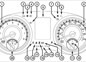
280 UNDERSTANDING YOUR INSTRUMENT PANEL INSTRUMENT CLUSTER
INSTRUMENT CLUSTER DESCRIPTIONS
1. Tachometer The red segments indicate the maximum permissible engine revolutions per minute (RPM x 1000) for each gear range. Before reaching the red area, ease up on the accelerator. 2. Park/Headlight ON Indicator — If Equipped
This indicator will illuminate when the park lights or headlights are turned on.
3. Turn Signal Indicators
The arrow will flash with the exterior turn signal when the turn signal lever is operated.
UNDERSTANDING YOUR INSTRUMENT PANEL 281
If the vehicle electronics sense that the vehicle is driven more than 1 mile (1.6 km) with either turn signal on, a continuous chime will sound to alert you to turn the signals off. If either indicator flashes at a rapid rate, check for a defective outside light bulb. 4. Front Fog Light Indicator — If EquippedThis indicator will illuminate when the front fog lights are on.
5. High Beam Indicator
This indicator shows that the high beam head- lights are on. Push the multifunction lever forward to switch the headlights to high beam, and pull toward yourself (normal position) to return to low beam.
282 UNDERSTANDING YOUR INSTRUMENT PANEL 6. Odometer Display / Electronic Vehicle Information Center (EVIC) Display
Odometer Display The odometer display shows the total distance the ve- hicle has been driven. U.S. Federal regulations require that upon transfer of vehicle ownership, the seller certify to the purchaser the correct mileage that the vehicle has been driven. If your odometer needs to be repaired or serviced, the repair technician should leave the odometer reading the same as it was before the repair or service. If s/he cannot do so, then the odometer must be set at zero, and a sticker must be placed in the door jamb stating what the mileage was before the repair or service. It is a good idea for you to make a record of the odometer reading before the repair/ service, so that you can be sure that it is properly reset, or that the door jamb sticker is accurate if the odometer must be reset at zero.
Electronic Vehicle Information Center (EVIC) Display The Electronic Vehicle Information Center (EVIC) fea- tures a driver-interactive display that is located in the instrument cluster. For further information, refer to “Electronic Vehicle Information Center (EVIC)”. The Shift Lever Indicator is self-contained within the EVIC display. It displays the gear position of the auto- matic transmission. NOTE: • You must apply the brakes before shifting from PARK. • The highest available transmission gear is displayed in the lower right corner of the Electronic Vehicle Infor- mation Center (EVIC) whenever the Electronic Range Select (ERS) feature is active. Use the +/- selector on the shift lever to activate ERS. Refer to “Automatic Transmission” in “Starting And Operating” for further information.
7. Tire Pressure Monitoring Telltale Light — If Equipped
Each tire, including the spare (if provided), should be checked monthly when cold and inflated to the inflation pressure recommended by the vehicle manufacturer on the vehicle placard or tire inflation pressure label. (If your vehicle has tires of a different size than the size indicated on the vehicle placard or tire inflation pressure label, you should determine the proper tire inflation pressure for those tires.) As an added safety feature, your vehicle has been equipped with a Tire Pressure Monitoring System (TPMS) that illuminates a low tire pressure telltale when
UNDERSTANDING YOUR INSTRUMENT PANEL 283
one or more of your tires is significantly under-inflated. Accordingly, when the low tire pressure telltale illumi- nates, you should stop and check your tires as soon as possible, and inflate them to the proper pressure. Driving on a significantly under-inflated tire causes the tire to overheat and can lead to tire failure. Under-inflation also reduces fuel efficiency and tire tread life, and may affect the vehicle’s handling and stopping ability. Please note that the TPMS is not a substitute for proper tire maintenance, and it is the driver’s responsibility to maintain correct tire pressure, even if under-inflation has not reached the level to trigger illumination of the TPMS low tire pressure telltale.284 UNDERSTANDING YOUR INSTRUMENT PANEL Your vehicle has also been equipped with a TPMS malfunction indicator to indicate when the system is not operating properly. The TPMS malfunction indicator is combined with the low tire pressure telltale. When the system detects a malfunction, the telltale will flash for approximately one minute and then remain continuously illuminated. This sequence will continue upon subse- quent vehicle start-ups as long as the malfunction exists. When the malfunction indicator is illuminated, the sys- tem may not be able to detect or signal low tire pressure as intended. TPMS malfunctions may occur for a variety of reasons, including the installation of replacement or alternate tires or wheels on the vehicle that prevent the TPMS from functioning properly. Always check the TPMS malfunction telltale after replacing one or more tires or wheels on your vehicle, to ensure that the replacement or alternate tires and wheels allow the TPMS to continue to function properly.
CAUTION!
The TPMS has been optimized for the original equipment tires and wheels. TPMS pressures and warning have been established for the tire size equipped on your vehicle. Undesirable system opera- tion or sensor damage may result when using re- placement equipment that is not of the same size, type, and/or style. Aftermarket wheels can cause sensor damage. Do not use tire sealant from a can or balance beads if your vehicle is equipped with a TPMS, as damage to the sensors may result.
8. Malfunction Indicator Light (MIL)
The Malfunction Indicator Light (MIL) is part of an onboard diagnostic system, called OBD, that monitors engine and automatic transmission con- trol systems. The light will illuminate when the key is in the ON/RUN position, before engine start. If the bulb does not come on when turning the key from OFF to ON/RUN, have the condition checked promptly. Certain conditions, such as poor fuel quality, etc., may illuminate the MIL after engine start. The vehicle should be serviced if the light stays on through several of your typical driving cycles. In most situations, the vehicle will drive normally and will not require towing.
UNDERSTANDING YOUR INSTRUMENT PANEL 285
CAUTION!
Prolonged driving with the MIL on could cause dam- age to the engine control system. It also could affect fuel economy and drivability. If the MIL is flashing, severe catalytic converter damage and power loss will soon occur. Immediate service is required.
WARNING!
A malfunctioning catalytic converter, as referenced above, can reach higher temperatures than in normal operating conditions. This can cause a fire if you drive slowly or park over flammable substances such as dry plants, wood, cardboard, etc. This could result in death or serious injury to the driver, occupants or others.
286 UNDERSTANDING YOUR INSTRUMENT PANEL 9. Speedometer Indicates vehicle speed. 10. Fuel Door Reminder
The arrow in this symbol is a reminder that the Fuel Filler Door is located on the left side of the vehicle.
11. Fuel Gauge The pointer shows the level of fuel in the fuel tank when the ignition switch is in the ON/RUN position. 12. Air Bag Warning Light
This light will turn on for four to eight seconds as a bulb check when the ignition switch is first turned to ON/RUN. If the light is either not on during starting, stays on, or turns on while driving, have the system inspected at an authorized dealer as soon as possible. Refer to “Occupant Restraints” in “Things To Know Before Starting Your Vehicle” for further information.
13. Anti-Lock Brake (ABS) Light
This light monitors the Anti-Lock Brake System (ABS). The light will turn on when the ignition switch is turned to the ON/RUN position and may stay on for as long as four seconds.
If the ABS light remains on or turns on while driving, it indicates that the Anti-Lock portion of the brake system is not functioning and that service is required. However, the conventional brake system will continue to operate normally if the BRAKE warning light is not on. If the ABS light is on, the brake system should be serviced as soon as possible to restore the benefits of Anti-Lock brakes. If the ABS light does not turn on when the ignition switch is turned to the ON/RUN position, have the light inspected by an authorized dealer.
14. Sport Mode