- 1997 Chevrolet Corvette Owners Manuals
- Chevrolet Corvette Owners Manuals
- 2001 Chevrolet Corvette Owners Manuals
- Chevrolet Corvette Owners Manuals
- 2015 Chevrolet Corvette Owners Manuals
- Chevrolet Corvette Owners Manuals
- 1993 Chevrolet Corvette Owners Manuals
- Chevrolet Corvette Owners Manuals
- 2006 Chevrolet Corvette Owners Manuals
- Chevrolet Corvette Owners Manuals
- 1994 Chevrolet Corvette Owners Manuals
- Chevrolet Corvette Owners Manuals
- 2013 Chevrolet Corvette Owners Manuals
- Chevrolet Corvette Owners Manuals
- 1999 Chevrolet Corvette Owners Manuals
- Chevrolet Corvette Owners Manuals
- 2011 Chevrolet Corvette Owners Manuals
- Chevrolet Corvette Owners Manuals
- 2012 Chevrolet Corvette Owners Manuals
- Chevrolet Corvette Owners Manuals
- 2016 Chevrolet Corvette Owners Manuals
- Chevrolet Corvette Owners Manuals
- 2005 Chevrolet Corvette Owners Manuals
- Chevrolet Corvette Owners Manuals
- 2004 Chevrolet Corvette Owners Manuals
- Chevrolet Corvette Owners Manuals
- 2014 Chevrolet Corvette Owners Manuals
- Chevrolet Corvette Owners Manuals
- 2009 Chevrolet Corvette Owners Manuals
- Chevrolet Corvette Owners Manuals
- 1996 Chevrolet Corvette Owners Manuals
- Chevrolet Corvette Owners Manuals
- 2002 Chevrolet Corvette Owners Manuals
- Chevrolet Corvette Owners Manuals
- 2000 Chevrolet Corvette Owners Manuals
- Chevrolet Corvette Owners Manuals
- 2010 Chevrolet Corvette Owners Manuals
- Chevrolet Corvette Owners Manuals
- 2007 Chevrolet Corvette Owners Manuals
- Chevrolet Corvette Owners Manuals
- 2008 Chevrolet Corvette Owners Manuals
- Chevrolet Corvette Owners Manuals
- 2003 Chevrolet Corvette Owners Manuals
- Chevrolet Corvette Owners Manuals
- 1995 Chevrolet Corvette Owners Manuals
- Chevrolet Corvette Owners Manuals
- 1998 Chevrolet Corvette Owners Manuals
- Chevrolet Corvette Owners Manuals
- Download PDF Manual
-
position, write “Middle.” The switch settings written down in Step 3
now become the button strokes to be entered into the Universal Home Remote in Step 5. Be sure to enter the switch settings written down in Step 3, in order from left to right, into the Universal Home Remote, when completing Step 5.4. From inside the vehicle, first firmly press all three buttons at the same time for about three seconds. Release the buttons to put the Universal Home Remote into programming mode.
5. The indicator lights blink slowly. Enter each switch
setting from Step 3 into the vehicle’s Universal Home Remote. You have two and one-half minutes to complete Step 5. Now press one button on the Universal Home Remote for each switch setting as follows: • If you wrote “Left,” press the left button in the
vehicle.
• If you wrote “Right,” press the right button in the
vehicle.
• If you wrote “Middle,” press the middle button in
the vehicle.
3-46
6. After entering all of the switch positions, again, firmly press and release all three buttons at the same time. The indicator lights turn on.
7. Press and hold the button that will be used to control the garage door until the garage door moves. The indicator light above the selected button should slowly blink. This button may need to be held for up to 55 seconds.
8. Immediately release the button when the garage door moves. The indicator light blinks rapidly until programming is complete.
9. Press and release the same button again. The garage door should move, confirming that programming is successful and complete. To program another Fixed Code device such as an additional garage door opener, a security device, or home automation device, repeat Steps 1-9, choosing a different button in Step 7 than what was used for the garage door opener.
Using Universal Home Remote Press and hold the appropriate button for at least half of a second. The indicator light comes on while the signal is being transmitted. Operation can occur: • If the vehicle is in accessory mode. • If the vehicle is in running. • If the vehicle is in Retained Accessory Mode (RAP). See Retained Accessory Power (RAP) on page 3-23
for more information.• Up to an additional 10 minutes after RAP finishes. • Up to 10 minutes after any door is opened. Reprogramming Universal Home Remote Buttons Any of the three buttons can be reprogrammed by repeating the instructions.
3-47
Erasing Universal Home Remote Buttons The programmed buttons should be erased when the vehicle is sold or the lease ends. To erase either Rolling Code or Fixed Code on the Universal Home Remote device: 1. Press and hold the two outside buttons at the same
time for approximately 20 seconds, until the indicator lights, located directly above the buttons, begin to blink rapidly.
2. Once the indicator lights begin to blink, release both
buttons. The codes from all buttons are erased.
For help or information on the Universal Home Remote System, call the customer assistance phone number under Customer Assistance Offices on page 8-6.
Storage Areas
Glove Box Open the glove box by lifting up on the lever. Use the key to lock and unlock the lighted glove box.
Cupholders Two cupholders are located on the center console next to the shift lever. Slide the handle from the left to the right side to access the lid.
Center Console Storage To use this storage area, pull the cover up on the driver side front edge of the console and swing it to the passenger side.
Floor Mats The floor mats are specially designed to remain in position under your feet and out of reach of the accelerator pedal. The driver’s side floor mat is held in place by two locator hooks and the passenger’s side is held in place by one.
3-48
Be sure that the driver’s side floor mat is properly placed on the floor so that it does not block the movement of the accelerator pedal. How to Remove and Replace the Floor Mats
To remove the floor mats, pull up on the rear of the mat to disconnect from the locator hooks.
Rear Storage Area Two rear storage compartments are located in the floor of the rear hatch/trunk area.
To reinstall the floor mats, line up the openings in the floor mat over the locator hooks and push down into place.
Convertible shown, Coupe similar
To access a storage compartment, pull up to open the cover. The covers cannot be removed. For Z06, ZR1 and Grand Sport models, the right rear compartment stores the battery and cannot be used for storage. Notice: Do not store heavy or sharp objects in the rear storage compartments located in the hatch/trunk area. The objects could damage the underbody.
3-49
Rear Trunk Partition For vehicles with the power convertible top option only, there is a trunk partition to keep cargo from getting in the way of the convertible top. The trunk partition must be in place for the convertible top to move. If the trunk partition is not properly in place the ATTACH TRUNK PARTITION Driver Information Center (DIC) message displays. See DIC Warnings and Messages on page 4-51 for more information. The trunk partition is a flat carpeted board with a horizontal flap that can be attached to the top of the trunk to divide the storage compartment or it stores flat when not in use.
3-50
Pull the divider up and snap it onto the snaps on both sides of the trunk.
Convenience Net Use the convenience net, located in the rear, to store small loads as far forward as possible. The net should not be used to store heavy loads.
Cargo Cover For vehicles with this feature, the security shade can provide hidden storage in the rear area of the vehicle. The shade is also helpful in blocking the glare from the removable roof when it is stored in the rear compartment. Using the Cargo Cover
1. Hook the elastic loops on the front corners (A) of the shade to the T-nuts located on the front corners of the rear hatch frame.
2. Hook the elastic loops on the rear corners (B) of the
shade to the hooks recessed inside the rear hatch frame, near the rear corners.
3. Grasp the loop at the rear center of the shade and
wrap it around the striker assembly.
4. Push the loop to the
top of the striker (base plate).
3-51
If you drop or rest a roof panel on its
Notice: edges, the roof panel, paint and/or weatherstripping may be damaged. Always place the roof panel in the stowage receivers after removing it from the vehicle. 1. Park on a level surface and set the parking brake.
Shift an automatic transmission into P (Park). Shift a manual transmission into N (Neutral).
2. Make sure the ignition is off. 3. Lower both sun visors. 4. Open the rear hatch and remove any items that
may interfere with proper storage of the roof panel.
5. Lower the windows.
There are two release latches on the front of the roof panel and one rear release latch on the back of the roof panel.
Roof Panel On vehicles with a removable roof panel, follow the procedures when removing or installing it.
Removing the Roof Panel
{ WARNING:
Do not try to remove a roof panel while the vehicle is moving. Trying to remove the roof panel while the vehicle is moving could cause an accident. The panel could fall into the vehicle and cause you to lose control, or it could fly off and strike another vehicle. You or others could be injured. Remove the roof panel only when the vehicle is parked.
Until you are sure you can remove the panel alone, have someone help you.
3-52
6. To unlock the release latches on the front of the
roof panel, grasp each handle and pull it outward.
The driver’s side handle moves toward the driver’s door. The passenger’s side handle moves toward the passenger’s door.
3-53
Storing the Roof Panel
{ WARNING:
If a roof panel is not stored properly, it could be thrown about the vehicle in a crash or sudden maneuver. People in the vehicle could be injured. Whenever you store a roof panel in the vehicle, always be sure that it is stored securely in the proper location.
Notice: If you drop or rest a roof panel on its edges, the roof panel, paint and/or weatherstripping may be damaged. Always place the roof panel in the stowage receivers after removing it from the vehicle.
7. To unlock the rear of the roof panel’s rear release latch, press the back of the release handle (B). Then press the button on the front of the release handle (A).
Pull down the latch lever.
8. Stand on one side of the vehicle, and if necessary,
have someone stand on the other side. Together, carefully lift the front edge of the roof panel up and forward.
9. When the roof panel is loosened from the vehicle, one person should grasp the roof panel as close to the center as possible and lift it away from the vehicle.
3-54
1. Turn the roof panel so that the front edge of the
panel is facing the storage area.
Installing the Roof Panel
2. Insert the roof panel so
that the outside front edges line up between the receiver covers. Push forward on the roof panel until it stops.
{ WARNING:
An improperly attached roof panel may fall into or fly off the vehicle. You or others could be injured. After installing the roof panel, always check that it is firmly attached by pushing up on the underside of the panel. Check now and then to be sure the roof panel is firmly in place.
3. Gently place the roof
panel down so that the back pins on the roof panel drop into the receivers in the back of the storage area.
Press down firmly to seat the pins in the receivers.
Notice: If you drop or rest a roof panel on its edges, the roof panel, paint and/or weatherstripping may be damaged. Always place the roof panel in the stowage receivers after removing it from the vehicle. In most cases, it makes it easier if two people install the roof panel. 1. Park on a level surface and set the parking brake.
Shift an automatic transmission into P (Park). Shift a manual transmission into N (Neutral).
2. Check that the front release latches and the rear release latch on the vehicle’s roof opening are in their opened positions before attempting to install the roof panel.
3-55
3. To remove the roof panel from the rear storage area of the vehicle, pull up on the rear edge and remove it from the storage area.
4. Carefully place the roof panel over the top of the
vehicle.
5. Position the rear edge of the roof panel to the weatherstrip on the back of the roof opening. Then align and fit the pins at the rear of the roof panel inside the openings in the rear overhead weatherstrip. Gently lower the front edge of the roof panel to the front of the roof opening.
6. Turn the front release handles inward so that they latch to the closed position.
7. Push up on the handle of the rear roof release handle to latch its hook in the closed position. 8. Push and pull the roof panel up and down and side-to-side to ensure the roof panel is securely installed.
Convertible Top
Convertible Top (Manual) For care and cleaning of the convertible top, see Convertible Top on page 6-98 under “Service and Appearance Care”. High pressure car washes may cause water to enter the vehicle. If the vehicle has this feature, the following procedures explain the proper operation of the manual convertible top.
3-56
The parts of the manual convertible top that are used when lowering and raising it are:
A. Front Edge of the Convertible Top B. Rear Edge of the Convertible Top C. Tonneau Cover
Notice: Leaving the convertible top down and exposing the interior of your vehicle to outdoor conditions may cause damage. Always close the convertible top if leaving your vehicle outdoors.
Notice: Lowering the convertible top when there are objects in the storage area could damage it or break the glass rear window. Always verify that no objects are in the storage area before lowering the convertible top. Notice: Lowering the top if it is damp, wet, or dirty can cause stains, mildew, and damage to the inside of your vehicle. Dry off the top before lowering it. Notice: weather (0°F/-18°C or lower), you may damage top components. Do not lower the top in cold weather. Notice: while the vehicle is in motion, you could damage the top or the top mechanism. The repairs would not be covered by your warranty. Always put an automatic transmission in (P) Park or a manual transmission in (N) Neutral before raising or lowering the convertible top.
If you lower the top on your vehicle in cold
If you raise or lower the convertible top
3-57
Lowering the Manual Convertible Top 1. Park on a level surface. Shift an automatic
transmission into P (Park) and set the parking brake. Shift a manual transmission into N (Neutral) and set the parking brake.
2. Make sure the ignition is off. 3. Make sure the trunk is closed.
4. The convertible top front latch, located above the inside rearview mirror, must be unlocked. Pull the convertible top front latch down and turn it clockwise to unlock it.
3-58
5. Lift upward on the front edge (A) of the convertible top off of the windshield frame. Then lift upward on the rear edge (B) of the convertible top so it is vertical to the tonneau cover (C). The front edge (A) and rear edge (B) should be straight up.
If the vehicle has lost battery power, the tonneau cover (C) can still be opened using the manual release cable. The tonneau cover emergency manual release cable is located underneath the carpeting behind the passenger’s seat head restraint, on the underside forward edge of the tonneau cover. To access the cable, lift and pull back the carpeting. Also, see Hatch on page 3-14 for information on the emergency trunk release handle.
If you lower the convertible top into the
Notice: storage compartment and the rear edge of the top is not in the full-down position, you could damage the top. Always verify that the rear edge of the convertible top is in the full-down position before lowering the top into the storage compartment.
3-59
6. Tilt the driver’s seatback forward and press the
tonneau cover release button located on the underside of the tonneau cover (C) behind the driver’s seat. Then raise the tonneau cover (C). If the tonneau cover does not release and three chimes are heard, check to make sure the trunk lid is closed. Also, the cover will not release if the vehicle alarm is armed. After pressing the release button, the driver’s and passenger’s door glass should retract to the full-down position.
7. Pull the cable to release the tonneau cover.
8. Push forward on the front edge (A) of the
convertible top to allow the rear edge (B) of the convertible top to be moved to its full-down position.
3-60
9. Then move the top rearward to its fully-stored
position.
10. After the top is stored, apply one even push on the center of the front edge (A) of the convertible top to assure that the top is fully retracted.
11. Close the tonneau cover (B) by pressing down on it
with a swift, firm motion.
Raising the Manual Convertible Top 1. Park on a level surface. Shift an automatic
transmission into P (Park) and set the parking brake. Shift a manual transmission into N (Neutral) and set the parking brake.
2. Lower both windows. 3. Make sure the ignition is off. 4. Tilt the driver’s seat forward and press the tonneau
cover release button, or use the manual release cable if battery power has been lost. See Step 6
under “Lowering the Manual Convertible Top” earlier in this section. After pressing the release button, the driver’s and passenger’s door glass should retract to the full-down position, if they have not already been lowered.5. Lift the tonneau cover.
3-61
6. Pull the convertible top up by firmly gripping the
front edge (A) near the center and applying a brisk upward and forward motion to get the top in the full-up position.
7. Lift the rear edge (B) of the convertible top to its full-up position by first raising the front edge (A). 8. Close the tonneau cover (C) by pushing it down
with a swift, firm motion.
9. Lower the rear edge (B) of the convertible top by
first slightly pushing the front edge (A) of the convertible top forward.
10. Push the front edge (A) of the convertible top down
from the outside of the vehicle, or pull the front edge (A) of the convertible top down from the center pull-down handle located in the inside of the vehicle.
3-62
To operate the power convertible top use the following steps. Notice: Leaving the convertible top down and exposing the interior of your vehicle to outdoor conditions may cause damage. Always close the convertible top if leaving your vehicle outdoors. Notice: Lowering the convertible top when there are objects in the storage area could damage it or break the glass rear window. Always verify that no objects are in the storage area before lowering the convertible top. Notice: Lowering the top if it is damp, wet, or dirty can cause stains, mildew, and damage to the inside of your vehicle. Dry off the top before lowering it. Notice: weather (0°F/-18°C or lower), you may damage top components. Do not lower the top in cold weather. Notice: while the vehicle is in motion, you could damage the top or the top mechanism. The repairs would not be covered by your warranty. Always put an automatic transmission in (P) Park or a manual transmission in (N) Neutral before raising or lowering the convertible top.
If you lower the top on your vehicle in cold
If you raise or lower the convertible top
3-63
11. Pull the top front latch handle down and turn it
counterclockwise to lock the convertible top.
Convertible Top (Power) For care and cleaning of the convertible top see Convertible Top on page 6-98 under “Service and Appearance Care”. High pressure car washes may cause water to enter the vehicle.
Lowering the Power Convertible Top 1. Park on a level surface. Start the engine. Shift an
automatic transmission into P (Park) and set the parking brake. Shift a manual transmission into N (Neutral), and set the parking brake.
2. Make sure the trunk is closed and the rear trunk
partition in the rear storage area is in the fastened upright position, and that no objects are forward of the divider. See “Rear Trunk Partition” under Rear Storage Area on page 3-49.
Push upward on the front edge. The windows will automatically lower.
4. Push and hold the
bottom of the power convertible top button, located to the left of the steering wheel, on the instrument panel.
The windows will automatically lower and the convertible top will lower into the rear of the vehicle. A chime will sound when the convertible top has lowered completely. If the radio is on the sound may be muted for a brief time due to a new audio system equalization being loaded. If the convertible top is operated multiple times, the engine should be running to prevent drain on the vehicle’s battery. Under certain conditions, the Driver Information Center (DIC) may display a message regarding the power convertible top. See DIC Warnings and Messages on page 4-51 for more information.
3. Release the convertible top front latch, located above the inside rearview mirror, by pulling and turning it clockwise toward the driver’s door.
3-64
4. After the convertible top is completely raised,
release the power convertible top button.
5. Pull the convertible front top latch down and turn it
counterclockwise to lock the convertible top.
If you raise or lower the convertible top
Raising the Power Convertible Top Notice: while the vehicle is in motion, you could damage the top or the top mechanism. The repairs would not be covered by your warranty. Always put an automatic transmission in (P) Park or a manual transmission in (N) Neutral before raising or lowering the convertible top. 1. Park on a level surface. Start the engine. Shift an
automatic transmission into P (Park) and set the parking brake. Shift a manual transmission into N (Neutral) and set the parking brake.
2. Make sure the trunk lid is closed and the rear trunk partition in the rear storage area is in the fastened upright position, and that no objects are forward of the divider. See “Rear Trunk Partition” under Rear Storage Area on page 3-49.
3. Push and hold the top of the power convertible top
button. The top will raise and the windows will lower if they were in the raised position. A chime will sound when the top is raised completely.
If the radio is on the sound may be muted for a brief time due to a new audio system equalization being loaded.
3-65
If the vehicle has lost power, the convertible top can still be raised by releasing pressure on the hydraulic pump, located under the passenger’s side of the tonneau cover, by using the following steps. The carpet liner on the passenger’s side must be pulled back to access the hydraulic pump. Manual operation of the power convertible top cannot be attempted for five minutes from the last time the convertible top button was pressed if the top is not completely stowed, with the top down and the tonneau latched, or closed, with the front top latch locked in place, at the time the convertible top button was released.
3-66
1. Open the tonneau cover by pulling the emergency
release cable. The tonneau cover emergency release cable is located behind the passenger’s seat head restraint, on the underside forward edge of the tonneau cover. Also, see Hatch on page 3-14 for information on the emergency trunk release handle. Be careful when opening the tonneau cover by hand. If the tonneau cover is opened quickly, damage can occur to the hinging mechanism, which can prevent proper operation of the convertible top.
When power is restored to the vehicle, the hydraulic bolt must be tightened, by turning it clockwise. The power convertible top button can then be used to lower or raise the convertible top. If the power convertible top is operated multiple times, the engine should be running to prevent drain on the vehicle’s battery. Under certain conditions, the Driver Information Center (DIC) may display a message regarding the power top. See DIC Warnings and Messages on page 4-51 for more information. If the battery has been disconnected, the power windows must be initialized for the power top to operate. See Power Windows on page 3-17 for more information.
3-67
2. Locate the pressure release bolt on the front side of
the hydraulic pump.
3. Use the wrench, located in the console, and
turn the pressure release bolt counterclockwise one revolution, to relieve pressure to the hydraulic pump. This will allow you to manually raise the convertible top.
4. Then follow the steps under raising the manual convertible top. See “Convertible Top (Manual)” under Convertible Top (Manual) on page 3-56
or Convertible Top (Power) on page 3-63.✍ NOTES
3-68
Section 4
Instrument Panel
Instrument Panel Overview ...............................4-3
Hazard Warning Flashers ................................4-3
Horn .............................................................4-3
Tilt Wheel .....................................................4-3
Turn Signal/Multifunction Lever .........................4-4
Turn and Lane-Change Signals (Auto Signal) .....4-5
Headlamp High/Low-Beam Changer ..................4-5
Flash-to-Pass .................................................4-5
Windshield Wipers ..........................................4-6
Windshield Washer .........................................4-6
Cruise Control ................................................4-7
Exterior Lamps .............................................4-11
Wiper Activated Headlamps ............................4-12
Headlamps on Reminder ................................4-12
Daytime Running Lamps (DRL) .......................4-12
Fog Lamps ..................................................4-13
Twilight Sentinel® ..........................................4-14
Exterior Lighting Battery Saver ........................4-15
Instrument Panel Brightness ...........................4-15
Courtesy Lamps ...........................................4-15
Entry/Exit Lighting .........................................4-15
Reading Lamps ............................................4-15
Battery Run-Down Protection ..........................4-16
Head-Up Display (HUD) .................................4-16
Accessory Power Outlet(s) .............................4-20
Ashtray(s) and Cigarette Lighter ......................4-21Climate Controls ............................................4-21
Dual Automatic Climate Control System ...........4-21
Outlet Adjustment .........................................4-26
Passenger Compartment Air Filter ...................4-27
Warning Lights, Gages, and Indicators ............4-28
Instrument Panel Cluster ................................4-29
Speedometer and Odometer ...........................4-31
Tachometer .................................................4-31
Safety Belt Reminders ...................................4-31
Airbag Readiness Light ..................................4-32
Passenger Airbag Status Indicator ...................4-33
Voltmeter Gage ............................................4-34
One-to-Four Shift Light(Manual Transmission) ...............................4-35
Brake System Warning Light ..........................4-35
Antilock Brake System (ABS) WarningLight ........................................................4-36
Traction Control System (TCS) Warning
Light ........................................................4-37
Active Handling System Light .........................4-38
Engine Coolant Temperature Gage ..................4-39
Tire Pressure Light .......................................4-39
Malfunction Indicator Lamp .............................4-404-1
Section 4
Instrument Panel
Engine Oil Pressure Gage .............................4-43
Security Light ...............................................4-44
Fog Lamp Light ............................................4-44
Lights On Reminder ......................................4-44
Highbeam On Light .......................................4-44
Fuel Gage ...................................................4-45
Boost Gage (ZR1 Only) .................................4-46
Driver Information Center (DIC) .......................4-46
DIC Operation and Displays ...........................4-46
DIC Warnings and Messages .........................4-51
Other Messages ...........................................4-68
DIC Vehicle Personalization ............................4-69Audio System(s) .............................................4-78
Setting the Clock ..........................................4-78
Radio(s) ......................................................4-79
Using an MP3 ..............................................4-90
XM Radio Messages .....................................4-92
Navigation/Radio System ...............................4-93
Bluetooth® ...................................................4-93
Theft-Deterrent Feature ................................4-103
Audio Steering Wheel Controls ......................4-104
Radio Reception .........................................4-105
Diversity Antenna System .............................4-106
XM™ Satellite Radio Antenna System ............4-1064-2
Instrument Panel Overview
Tilt Wheel
Hazard Warning Flashers The hazard warning flashers warns others that you have a problem. The button is located near the center of the instrument panel. | : Press to make the front and rear turn signal lamps flash on and off. Press again to turn the flashers off. The hazard warning flashers work no matter what mode the ignition is in, even if the ignition is turned off. When the hazard warning flashers are on, the turn signals will not work.
Horn Press near or on the horn symbols on the steering wheel pad to sound the horn.
The lever is located on the left side of the steering column. To adjust the steering wheel: 1. Pull the lever toward you. 2. Move the steering wheel up or down into a
comfortable position.
3. Release the lever to lock the steering wheel in
place.
4-3
Telescopic Steering Column
Turn Signal/Multifunction Lever
For vehicles with this feature, the telescopic steering column switch is located on the right side of the steering column.
To adjust the telescopic steering column:
1. Push the switch forward to move the wheel away
from you.
2. Pull the switch toward you to move the wheel closer
to you.
The telescopic steering column position can be stored with your memory settings. See Memory Seat, Mirrors and Steering Wheel on page 2-4 for more information.
The lever on the left side of the steering column includes the following: G : Turn and Lane-Change Signals 3 : Headlamp High/Low-Beam Changer
# : Fog Lamps I : Cruise Control P : Exterior Lamps Control • Flash-to-Pass Feature. See Flash-to-Pass on
page 4-5.
Information for these features is on the pages following.
4-4
Turn and Lane-Change Signals (Auto Signal)
An arrow on the instrument panel cluster flashes in the direction of the turn or lane change.
Move the lever all the way up or down to signal a turn. Raise or lower the lever until the arrow starts to flash to signal a lane change. Release the lever and the turn signal automatically flashes three times. If more flashes are desired, continue to hold the lever. The lever returns to its starting position when it is released. If after signaling a turn or lane change the arrows flash rapidly or do not come on, a signal bulb may be burned out. Have the bulbs replaced. If the bulb is not burned out, check the fuse. See Fuses and Circuit Breakers on page 6-103.
Turn Signal on Chime A chime sounds if the turn signal has been on for more than three-quarters of a mile (1.2 km) of driving. If you need to leave the turn signal on for more than three-quarters of a mile (1.2 km), turn off the signal and then turn it back on. Headlamp High/Low-Beam Changer To change the headlamps from low beam to high, push the turn signal lever all the way forward. To change from high to low beam, pull the lever rearward.
While the high beams are on, this light on the instrument panel cluster will also be lit.
Flash-to-Pass To use the flash-to-pass feature, briefly pull the turn signal lever toward you. The high-beam indicator flashes to indicate to the other driver that you intend to pass. If the low-beam headlamps are off and the fog lamps are on, the fog lamps flash.
4-5
Windshield Wipers
The windshield wiper lever is located on the right side of the steering column. Move the lever to the following positions: 1 (High Speed): Fast wipes. 6 (Low Speed): Slow wipes. & (Delay): Use to set a delay between wipes. x (Delay Adjustment): Use for a delayed wiping cycle. Turn the intermittent adjust band down for a longer delay or up for a shorter delay. The wiper speed can only be manually adjusted when the lever is in this position.
4-6
9 (Off): Turns off the windshield wipers. 8 (Mist): Move all the way down to mist and release for a single wiping cycle. The windshield wipers will stop after one wipe. Hold the band on mist longer for more wipes.
Heavy snow or ice can overload the wipers. If this occurs, a circuit breaker will stop the wipers until the motor cools. Clear all ice and snow from the wiper blades before using them. If frozen to the windshield, carefully loosen them or thaw them. Damaged wiper blades should be replaced. See Windshield Wiper Blade Replacement on page 6-62.
Windshield Washer The lever on the right side of the steering column also controls the windshield washer. There is a button at the end of the lever. To spray washer fluid on the windshield, press the button and hold it. The washer will spray until you release the button. The wipers will continue to clear the window for about six seconds after the button is released and then stop or return to your preset speed.
{ WARNING:
{ WARNING:
In freezing weather, do not use your washer until the windshield is warmed. Otherwise the washer fluid can form ice on the windshield, blocking your vision.
If the fluid in the windshield washer fluid reservoir is low, the message CHECK WASHER FLUID will appear on the Driver Information Center (DIC) display. It will take 15 seconds after the bottle is refilled for this message to turn off. For information on the correct washer fluid to use, see Windshield Washer Fluid on page 6-45 and Recommended Fluids and Lubricants on page 7-9.
Cruise Control With cruise control, a speed of about 40 km/h (25 mph) or more can be maintained without keeping your foot on the accelerator. Cruise control does not work at speeds below about 40 km/h (25 mph). Cruise control will not work if the parking brake is set, or if the master cylinder brake fluid level is low.
Cruise control can be dangerous where you cannot drive safely at a steady speed. So, do not use the cruise control on winding roads or in heavy traffic. Cruise control can be dangerous on slippery roads. On such roads, fast changes in tire traction can cause excessive wheel slip, and you could lose control. Do not use cruise control on slippery roads.
If the vehicle is in cruise control, and has the Traction Control System (TCS), and it begins to limit wheel spin, the cruise control automatically disengages. See Traction Control System (TCS) on page 5-6. When road conditions allow the cruise control to be safely used again, it can be turned back on.
4-7
The vehicle has cruise control.
Setting Cruise Control
{ WARNING:
If you leave your cruise control on when you are not using cruise, you might hit a button and go into cruise when you do not want to. You could be startled and even lose control. Keep the cruise control switch off until you want to use cruise control.
1. Move the cruise control switch to on. 2. Get up to the speed desired. 3. Press T at the end of the lever and release it. 4. Take your foot off the accelerator pedal. When the cruise control is engaged, the CRUISE SET TO XX MPH message displays on the Driver Information Center (DIC). See Other Messages on page 4-68.
9 (Off): Turns the system off. R (On): Turns the system on. + (Resume/Accelerate): Use to make the vehicle accelerate or resume a previously set speed. T (Set): Press this button at the end of the lever to set the speed.
4-8
Resuming a Set Speed If the cruise control is set at a desired speed and then the brakes are applied, the cruise control is disengaged. But it does not need to be reset. Once the vehicle is going about 40 km/h (25 mph) or more, you can move the cruise control switch briefly from R to S . The vehicles goes back up to your chosen speed and stays there. If the switch is held at resume/accelerate the vehicle keeps going faster until the switch is released or the brake is applied. Do not hold the switch at resume/ accelerate, unless you want the vehicle to go faster. Increasing Speed While Using Cruise Control There are two ways to go to a higher speed: • Use the accelerator pedal to get to the higher speed. Press J at the end of the lever, then release the button and the accelerator pedal. The vehicle now cruises at the higher speed. If the accelerator pedal is held longer than 60 seconds, cruise control will turn off.
• Move the cruise switch from R to S . Hold it there
until desired speed is reached, and then release the switch. To increase the vehicle speed in small amounts, move the switch briefly to S . Each time this is done, the vehicle goes about 1.6 km/h (1 mph) faster.
Reducing Speed While Using Cruise Control • Press and hold the set button until the lower speed
desired is reached, then release it.
• To slow down in small amounts, briefly press J .
Each time this is done, the vehicle goes about 1.6 km/h (1 mph) slower.
Passing Another Vehicle While Using Cruise Control Use the accelerator pedal to increase the vehicle’s speed. When you take your foot off the pedal, the vehicle slows down to the cruise control speed set earlier.
4-9
Using Cruise Control on Hills How well the cruise control works on hills depends upon the vehicle’s speed, load, and the steepness of the hills. When going up steep hills, you might want to step on the accelerator pedal to maintain the vehicle’s speed. When going downhill, you might have to brake or shift to a lower gear to keep the vehicle’s speed down. When the brakes are applied the cruise control turns off. Cruise Control in Sport and Manual Paddle Shift Gear Selection When the vehicle is in S (Sport) and the manual paddle shift controls are not being used, cruise control operates in the same manner as D (Drive). When the vehicle is in S (Sport) and the manual paddle shift controls are being used, cruise control operates as follows: • If cruise control is active and a gear is selected with
the manual paddle shift controls, the vehicle speed is maintained in the driver selected gear and will not automatically up-shift or down-shift the transmission while the driver’s gear selection is active.
• If driving in hilly terrain, cruise control may not be
able to maintain vehicle speed if an up-shift or down-shift is not selected by the driver. While driving on hilly terrain and cruise control is active with a manual paddle shift gear selection, the driver must select the proper gear for the terrain or select D (Drive) on the gear range selector for full automatic transmission operation.
Ending Cruise Control To end a cruise control session, step lightly on the brake pedal. If the vehicle has a manual transmission, lightly tapping the clutch will also end a cruise control session. Move the cruise control switch to 9 to turn the system completely off. When cruise control is disengaged, the CRUISE DISENGAGED message displays on the Driver Information Center (DIC). See DIC Warnings and Messages on page 4-51. Erasing Speed Memory The cruise control set speed memory is erased when the cruise control or the ignition is turned off.
4-10
Exterior Lamps
The exterior lamp control is located to the left of the steering wheel on the multifunction lever. O (Exterior Lamp Control): Turn the band with this symbol on it to operate the exterior lamps. The exterior lamp band has four positions: O (Off): Turns off all lamps. AUTO (Automatic): Sets the exterior lamps to automatic mode. AUTO mode turns the exterior lamps on and off depending on how much light is available outside the vehicle.
To override AUTO mode, turn the control to off.
To reset to AUTO mode turn the control to exterior lamps and then back to AUTO. Automatic mode also resets when the vehicle is turned off and then back on again if the control is left in the AUTO position. ; (Parking Lamp): Turns on the parking lamps together with the following: • Sidemarker Lamps • Taillamps • License Plate Lamps • Instrument Panel Lights The parking brake indicator light comes on and stays on when the parking lamps are on with the engine off and the ignition to ACC/ACCESSORY. 5 (Headlamps): Turns on the headlamps, together with the previously listed lamps and lights.
4-11
Wiper Activated Headlamps This feature activates the headlamps and parking lamps after the windshield wipers have been in use for approximately 15 seconds and deactivates and returns to ambient lighting conditions 15 seconds after the wipers are turned off. If the exterior lamp control has been turned off or is in the parking lamp position while the wiper control is active in any position, the HEADLAMPS SUGGESTED message appears on the Driver Information Center (DIC). See DIC Warnings and Messages on page 4-51. When the ignition is turned off, the wiper-activated headlamps will immediately turn off.
Headlamps on Reminder A warning chime will sound if the exterior lamp control is left on in either the headlamp or parking lamp position and the driver’s door is opened with the ignition off.
Daytime Running Lamps (DRL) Daytime Running Lamps (DRL) can make it easier for others to see the front of your vehicle during the day. Fully functional daytime running lamps are required on all vehicles first sold in Canada. The DRL system makes the front turn signal lamps come on when the following conditions are met: • It is still daylight and the ignition is on. • The exterior lamp control is in the AUTO position. • The transmission is not in P (Park) or the parking
brake is off.
• The parking brake is off or the vehicle speed is
greater than 8 mph (13 km/h).
When DRL are on, only the front turn signal lamps will be on. The parking lamps, taillamps, instrument panel lights, or other exterior lamps will not be on when the DRL are being used. When it is dark enough outside, the front turn signal lamps turn off and the normal low-beam headlamps turn on.
4-12
When it is bright enough outside, the regular lamps go off, and the front turn signal lamps will take over. If the vehicle is started in a dark garage, the automatic headlamp system comes on immediately. Once the vehicle leaves the garage, it takes approximately one minute for the automatic headlamp system to change to DRL if it is light outside. During that delay, the instrument panel cluster may not be as bright as usual. Make sure the instrument panel brightness knob is in the full bright position. See Instrument Panel Brightness on page 4-15 for more information. If it is dark enough outside and the exterior lamp control is off, a HEADLAMPS SUGGESTED message will display on the Driver’s Information Center (DIC). See DIC Warnings and Messages on page 4-51. Turning the exterior lamp control to off a second time, or turning on the headlamps will remove the HEADLAMPS SUGGESTED message in the DIC. If the parking lamps or the fog lamps were turned on instead, the HEADLAMPS SUGGESTED message will continue to be displayed. The regular headlamp system should be turned on when needed.
To turn off the DRL, turn the exterior lamp control to the off position or shift into P (Park). The DRL will stay off until the control is toggled again or the vehicle is shifted out of P (Park). This procedure applies only to vehicles first sold in the United States.
Fog Lamps Use fog lamps for better vision in foggy or misty conditions. The fog lamps control is located on the multifunction lever next to the exterior lamp control.
# (Fog Lamps): Turning the band to this position will turn the fog lamps on. When you turn the fog lamps on, the fog lamp light will appear on the instrument panel cluster to indicate that the fog lamps and the parking lamps are on. If you turn the high-beam headlamps on, the fog lamps will turn off. They will turn on again when you switch to low-beam headlamps. The ignition must be on for the fog lamps to operate. Some localities have laws that require the headlamps to be on along with the fog lamps.
4-13
After starting the vehicle, turn the exterior lamp control band on the multifunction lever to off and then release it. The lamps will remain off until the control band is turned to off again. Twilight Sentinel® also provides exterior illumination as you leave the vehicle. If Twilight Sentinel® has turned on the lamps when you turn off the ignition, the lamps will remain on until: • The exterior lamp switch is moved from off to the
parking lamp position, or
• A delay time that you select has elapsed. See “Personal Options” under DIC Vehicle Personalization on page 4-69 to select the delay time that you want. You can also select no delay time. If you turn off the ignition with the exterior lamp switch in the parking lamp or headlamp position, the Twilight Sentinel® delay will not occur. The lamps will turn off as soon as the switch is turned off. The regular headlamp system should be turned on when needed.
Twilight Sentinel® Twilight Sentinel® can turn the lamps on and off for you. A light sensor on top of the instrument panel makes the Twilight Sentinel® work, so be sure it is not covered. With Twilight Sentinel®, the following will happen: • When it is dark enough outside, the front turn signal
lamps (DRL) will go off, and the headlamps and parking lamps will come on. The other lamps that come on with headlamps will also come on.
• When it is bright enough outside, the headlamps will
go off, and the front turn signal lamps (DRL) will come on, as long as the exterior lamp switch is in the AUTO position.
If the vehicle is started in a dark garage, the automatic headlamp system come on immediately. Once the vehicle leaves the garage, it takes about one minute for the automatic headlamp system to change to DRL if it is light outside. During that delay, the instrument panel cluster may not be as bright as usual. Make sure the instrument panel brightness control is in full bright position. See Instrument Panel Brightness on page 4-15. You can idle the vehicle with the lamps off, even when it is dark outside.
4-14
Exterior Lighting Battery Saver If the manual parking lamps or headlamps have been left on, the exterior lamps will turn off as soon as the ignition is turned off or Retained Accessory Power (RAP) is active. This protects against draining the battery in case you have accidentally left the headlamps or parking lamps on. The battery saver does not work if the headlamps are turned on after the ignition switch is turned to off. If you need to leave the lamps on, use the exterior lamp control to turn the lamps back on.
Instrument Panel Brightness
The knob for this feature is located on the left side of the instrument panel.
Push the knob in to turn on the interior lights. Turn and hold the knob clockwise to brighten the lights or counterclockwise to dim them. During the day, this knob will adjust the instrument panel brightness and at night will adjust all interior lighting.
Be sure not to have this knob turned all the way down with the lamps on during the day. Your Driver Information Center (DIC) may not be visible. Courtesy Lamps When any door or the hatch/trunk lid is opened, the interior lamps will go on unless it is bright outside. You can also turn the courtesy lamps on and off by pressing the instrument panel brightness knob.
Entry/Exit Lighting With entry lighting, the interior lamps will come on when entering the vehicle. The interior lamps will come on for about 20 seconds when the engine is off. You can turn exit and entry lighting off by quickly turning the courtesy lamps on and off.
Reading Lamps The inside rearview mirror includes two reading lamps. The lamps will go on when a door is opened. When the doors are closed, press each lamp switch to turn them on individually.
4-15
Battery Run-Down Protection This vehicle has a feature to help prevent the battery from being drained in case any of the following lamps are left on; the underhood lamp, if your vehicle has this feature, vanity mirror lamps, cargo lamps, reading lamps, console or glove box lamps. If any of these lamps are left on, they will automatically time-out after about 10 minutes. To reset it, all of the above lamps must be turned off or the ignition key on.
Head-Up Display (HUD)
{ WARNING:
If the HUD image is too bright, or too high in your field of view, it may take you more time to see things you need to see when it is dark outside. Be sure to keep the HUD image dim and placed low in your field of view.
For vehicles with the Head-Up Display (HUD), you can see some of the driver information that appears on the instrument panel cluster.
The information may be displayed in English or metric units and appears as an image focused out toward the front of the vehicle. The HUD consists of the following information: • Speedometer • Turn Signal Indicators • High-Beam Indicator Symbol • Tachometer • Manual Paddle Shift Gear Indicator (If Equipped)
These displays on the HUD are for use when using the manual paddle shift controls to shift the transmission. See “Manual Paddle Shift” in Automatic Transmission Operation on page 3-26.
• Shift Light
This light is used for performance driving to indicate that the vehicle’s best performance level has been reached to shift the transmission into the next higher gear. An arrow pointing up will light up on the display just prior to reaching the engine fuel cut-off mode. This cut-off is about 6,500 RPM for the LS3 engine, 6,600 RPM for the LS9 & ZR1 engines and 7,000 RPM for the LS7 engine.
• Check Gages Warning • Engine Coolant Temperature Gage
4-16
• Transmission Fluid Temperature Gage, (Automatic
Transmission Vehicles Only) • Engine Oil Temperature Gage • Engine Oil Pressure Gage • G-Force Gage • Boost Gage (If Equipped) • Audio Functions, Street Mode Only • Navigation, Only with Navigation Radio,
Turn-by-Turn Guidance
There are three HUD modes that can be viewed in the HUD display. Press the MODE button to scroll through these modes in the following order:
Street Mode supports audio and navigation functions with your choice of tachometer settings.
Track Mode 1 supports the G-Force gage and minor gages with a circular tachometer.
Track Mode 2 supports G-Force gages, boost gage w/ZR1, and minor gages with a linear tachometer.
When the desired HUD display has been selected, release the MODE button. Within each mode, the display, can be further customized by pressing the PAGE button. Pressing this button in each mode will turn off and on the following: • Street Mode — No tachometer, circular tachometer,
and linear tachometer.
• Track Modes 1 and 2 — No minor gage, coolant
temperature, transmission oil temperature, engine oil temperature, engine oil pressure, and boost gage.
4-17
While in Track Mode 1 or 2, the maximum G value achieved during the current ignition cycle can be displayed by pressing and holding the PAGE button. The maximum G display will be shown until the PAGE button is released. The maximum G value display will be identical to the normal G value display, except the maximum G gage digits (X.XX G) and corresponding G gage bar will overwrite the current G value.
The HUD controls are located to the left of the steering wheel.
To adjust the HUD so it can be seen properly, do the following:
1. Start the engine and press the HUD dimmer control
all the way up by pressing the (+) button. The brightness of the HUD image is determined by the light conditions in the direction the vehicle is facing and where you have the HUD dimmer control set. If you are facing a dark object or a heavily shaded area, the HUD may anticipate that you are entering a dark area and may begin to dim. It is possible for sunlight to enter the HUD making it difficult to see the image. The display will return to normal when the sunlight is no longer entering the HUD.
Be sure to continue scanning the displays, controls and driving environment just as you would in a vehicle without HUD. If you never look at the instrument panel cluster, you may miss something important, such as a warning light. Under important warning conditions, the CHECK GAGES warning will illuminate in the HUD. View your Driver Information Center (DIC) for more information.
4-18
2. Adjust the seat to a comfortable driving position. If your seat position changes, the HUD may need to be re-adjusted.
3. Press the up or down arrows to center the HUD
image in your view. The HUD image can only be adjusted up and down, not side-to-side.
4. Press the dimmer control downward until the HUD
image is no brighter than necessary.
To turn HUD off, press and hold the (–) button until the HUD display turns off. If the sun comes out or it becomes cloudy, the HUD brightness may need to be adjusted again using the dimmer control. Polarized sunglasses could make the HUD image harder to see. The HUD information can be displayed in one of six languages including English, Spanish, French, German, Italian or Japanese. The speedometer can be displayed in either English or Metric units. To change the language and unit selections, see “OPTION” under DIC Operation and Displays on page 4-46.
Clean the inside of the windshield as needed to remove any dirt or film that reduces the sharpness or clarity of the HUD image. To clean the HUD, spray household glass cleaner on a soft, clean cloth. Wipe the HUD lens gently, then dry it. Do not spray cleaner directly on the lens because the cleaner could leak into the unit. If the ignition is on and the HUD image cannot be seen, check to see if: • Something is covering the HUD unit. • The HUD dimmer control is adjusted properly. • The HUD image is adjusted to the proper height. • Ambient light is low, in the direction the vehicle
is facing.
• A fuse is blown. See Fuses and Circuit Breakers on
page 6-103.
Keep in mind that the windshield is part of the HUD system. See Windshield Replacement on page 6-62.
4-19
Accessory Power Outlet(s) The accessory power outlet can be used to connect electrical equipment, such as a cellular phone. The accessory power outlet is located inside the center console storage compartment, on the forward left side. To use the outlet, remove the tethered cap. When not using it, always cover the outlet with the protective cap. Notice: Leaving electrical equipment plugged in for an extended period of time while the vehicle is off will drain the battery. Power is always supplied to the outlets. Always unplug electrical equipment when not in use and do not plug in equipment that exceeds the maximum 20 ampere rating. Certain electrical accessories may not be compatible with the accessory power outlet and could result in blown vehicle or adapter fuses. If you experience a problem, see your dealer/retailer for additional information on accessory power outlets.
Notice: Adding any electrical equipment to the vehicle can damage it or keep other components from working as they should. The repairs would not be covered by the vehicle warranty. Do not use equipment exceeding maximum amperage rating of 20 amperes. Check with your dealer/retailer before adding electrical equipment. When adding electrical equipment, be sure to follow the installation instructions included with the equipment. We recommend that you see a qualified technician or your dealer/retailer for the proper installation of your equipment. Notice: damage not covered by the vehicle warranty. Do not hang any type of accessory or accessory bracket from the plug because the power outlets are designed for accessory power plugs only.
Improper use of the power outlet can cause
4-20
If papers, pins, or other flammable items
Ashtray(s) and Cigarette Lighter The ashtray and cigarette lighter are located on the instrument panel, in front of the shift lever. To use the ashtray, press on the indentation at the top of the door. Notice: are put in the ashtray, hot cigarettes or other smoking materials could ignite them and possibly damage the vehicle. Never put flammable items in the ashtray. Loose objects, such as paper clips, can lodge behind and beneath the ashtray lid and prevent movement of the lid. You should avoid putting small, loose objects near the ashtray. To use the cigarette lighter, push it in all the way and let go. When it is ready, it will pop back out by itself. Notice: Holding a cigarette lighter in while it is heating does not let the lighter back away from the heating element when it is hot. Damage from overheating can occur to the lighter or heating element, or a fuse could be blown. Do not hold a cigarette lighter in while it is heating.
Climate Controls
Dual Automatic Climate Control System With this system the heating, cooling, and ventilation can be controlled.
A. Driver Temperature
Controls B. Display C. Passenger Temperature
Control D. AUTO E. Recirculation
F. Air Conditioning G. Fan Control H. Air Delivery Mode
Control I. Defrost J. Rear Window
Defogger
4-21
When the vehicle is first started, the display shows the driver’s temperature setting, the outside temperature, the fan speed and the air delivery, for about 10 seconds. The outside temperature is shown in the center of the display. The digital display will show the readings in Fahrenheit or Celsius. See “Personal Options” under DIC Vehicle Personalization on page 4-69 for information on changing your display. Automatic Operation
AUTO (Automatic): Press the AUTO button to place the entire system in the automatic mode. When automatic operation is active, the system automatically controls the inside temperature, the air delivery mode, and the fan speed. After a ten second display of the current settings, the word AUTO, the driver’s temperature setting and the outside temperature will be shown. The system operates to reach the set temperature as quickly as possible. The AUTO control system works best with the windows up and the removable roof installed or the convertible top up. 1. Press the AUTO button. 2. Adjust the temperature to a comfortable setting
between 16°C (60°F) and 32°C (90°F). Choosing the coldest or warmest temperature setting will not cause the system to heat or cool any faster. A setting of 23°C (73°F) is suggested.
4-22
In cold weather, the system will start at reduced fan speeds to avoid blowing cold air into your vehicle until warmer air is available. The system starts out blowing air at the floor but may change modes automatically as the vehicle warms up to maintain the chosen temperature setting. The length of time needed for warm up depends on the outside temperature and the length of time that has elapsed since the vehicle was last driven.
3. Wait for the system to regulate. This may take from
10 to 30 minutes. Then adjust the temperature, if necessary.
Do not cover the solar sensor located in the center of the instrument panel, near the windshield. For more information on the solar sensor, see “Sensor” later in this section. Manual Operation
Driver Power/Temperature: Press the driver temperature knob to turn the climate control system off. This is the only setting that completely shuts off the fan. The digital display shows only the outside temperature. The driver and the passenger set temperature and the air intake mode can still be adjusted when the climate control is off.
Passenger Power/Temperature: Press the passenger temperature knob to turn the passenger’s climate control system on or off. Turn the knob to increase or decrease the temperature for the passenger. If the passenger’s climate control system is off, the driver’s temperature knob will control the temperature for the entire vehicle. x 9 w (Fan): Press to increase or decrease the fan speed. The fan speed setting will appear in the display.
Pressing the arrows will delete AUTO from the digital display. The fan graphics with the fan speed bars will be shown. The AUTO button must be pressed to return to the automatic fan control.
If the airflow seems low when the fan speed is at the highest setting, the passenger compartment air filter may need to be replaced. For more information, see Passenger Compartment Air Filter on page 4-27 and Scheduled Maintenance on page 7-3.
N (Air Delivery Mode Control): Press this button to manually lock in the current air delivery setting and to stop the automatic mode control. Pressing N deletes AUTO from the digital display and the mode graphics will be shown. To change the setting, press N again. The AUTO button must be pressed to return to the automatic mode selection.
To change the current mode, select one of the following: H (Vent): Air is directed to the instrument panel outlets, with some air directed to the floor outlets. % (Bi-Level): Air is divided between the instrument panel and floor outlets. 6 (Floor): Air is directed to the floor outlets, with some air directed to the windshield and side window defogger outlets. - (Floor/Defog): This mode clears the windows of fog or moisture. Air is directed to the windshield and the floor outlets, with a small amount to the side window outlets. In this mode, the system automatically turns off the recirculation and runs the air-conditioning compressor unless the outside temperature is at or below freezing. The recirculation mode cannot be selected while in the defog mode. 1 (Defrost): This mode clears the windows of fog or frost more quickly. Air is directed to the windshield, with a small amount directed to the side window outlets. The indicator light comes on and the digital display will show the defrost mode symbol and fan speed when the front defrost mode is being used. In this mode, the system automatically turns off the recirculation and runs the air-conditioning compressor, unless the outside temperature is at or below freezing.
4-23
Recirculation cannot be selected while in the defrost mode. Pressing 1 again will return the system to the last operating mode.
For severe ice conditions, turn the driver’s temperature knob to 32°C (90°F) while in defrost mode.
Do not drive the vehicle until all the windows are clear.
^ (Air Conditioning Off): Press to turn the air conditioning compressor off. Press AUTO to return to automatic operation. When in AUTO, the air conditioning compressor comes on automatically, as needed.
Air conditioning does not operate at temperatures below about 2°C to 4°C (35°F to 40°F). In temperatures above 4°C (40°F), the air conditioning cannot be turned off in defrost and defog, as it helps to remove moisture from the vehicle. It also helps to keep the windows clear. You may notice a slight change in engine performance when the air-conditioning compressor shuts off and turns on again. This is normal. The system is designed to make adjustments to help with fuel economy while still maintaining the selected temperature. On hot days, open the windows to let hot inside air escape; then close them. This helps to reduce the time it takes for the vehicle to cool down. It also helps the system to operate more efficiently.
For quick cool down on hot days press the AUTO button and adjust the temperature to a cool, comfortable setting. To achieve maximum cool down, do the following: 1. Select H mode. 2. Press ? . 3. Select the a/c on. 4. Select the coolest temperature. 5. Select the highest fan speed. Using these settings together for long periods of time may cause the air inside of your vehicle to become too dry. To prevent this from happening, after the air in the vehicle has cooled, turn the recirculation mode off. The air conditioning system removes moisture from the air, so a small amount of water might drip under the vehicle while idling or after turning off the engine. This is normal. ? (Recirculation): Press to turn the recirculation mode on or off. An indicator light comes on to show that recirculation is on. This mode prevents outside air from entering your vehicle. It can be used to prevent outside air and odors from entering your vehicle and to help cool the air inside your vehicle more quickly. Recirculation mode is not available in defrost or defog mode.
4-24
Sensors The solar sensor on the vehicle monitors the solar heat and uses the information to maintain the selected temperature when operating in AUTO mode by automatically adjusting the temperature, fan speed and air delivery system. The system may also supply cooler air to the side of the vehicle facing the sun. The recirculation mode will also be activated, as necessary. Do not cover the solar sensor located on the top of the instrument panel near the windshield or the system will not work properly. There is also a sensor located behind the front bumper. This sensor reads the outside air temperature and helps to maintain the temperature inside the vehicle. Any cover on the front of the vehicle could give a false reading in the temperature. If the outside temperature goes up, the displayed temperature will not change until: • The vehicle’s speed is above 19 km/h (12 mph) for
five minutes.
• The vehicle’s speed is above 52 km/h (32 mph) for
two and a half minutes.
These delays prevent false readings. If the temperature goes down, the outside temperature will be shown when you start the vehicle. If it has been turned off for less than three hours, the temperature will be recalled from the previous vehicle operation. There is also an inside temperature sensor located to the left of the ignition switch. The automatic climate control system uses this sensor to receive information, so if you block or cover it, the system will not function properly. Rear Window Defogger The rear window defogger uses a warming grid to remove fog or frost from the rear window. The rear window defogger only works when the engine is running. = (Rear Window Defogger): Press to turn the rear window defogger on or off. Be sure to clear as much snow from the rear window as possible. An indicator light comes on to show that the rear window defogger is on.
4-25
The rear window defogger turns off about 10 minutes after the button is pressed when traveling less than 48 km/h (30 mph). If turned on again, the defogger only runs for about five minutes before turning off. The defogger can also be turned off by turning off the engine. The vehicle has heated outside rearview mirrors. The mirrors will heat to help clear fog or frost from the surface of the mirrors when the rear window defogger button is pressed. For vehicles with a power convertible top, the rear window defogger and heated mirrors are automatically disabled when the power convertible top is moving or down. Notice: Do not use anything sharp on the inside of the rear window. If you do, you could cut or damage the warming grid, and the repairs would not be covered by the vehicle warranty. Do not attach a temporary vehicle license, tape, a decal or anything similar to the defogger grid.
Outlet Adjustment Use the tab located on the air outlets to change the direction of the airflow. Operation Tips • Clear away any ice, snow or leaves from the air
inlets at the base of the windshield that may block the flow of air into your vehicle.
• Use of non-GM approved hood deflectors may adversely affect the performance of the system. • Keep the area around the base of the instrument panel console and air path under the seats clear of objects to help circulate the air inside of your vehicle more effectively.
4-26
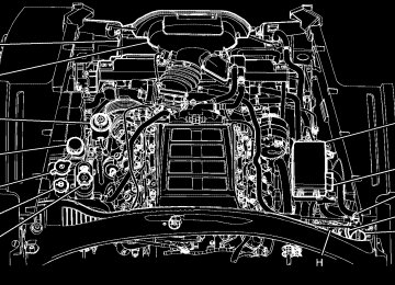
Passenger Compartment Air Filter The passenger compartment air filter removes certain particles from the air including pollen and dust particles. Reductions in airflow, which may occur more often in dusty areas, indicate that the filter may need to be replaced. See Scheduled Maintenance on page 7-3 for information on how often to replace the filter. Notice: Driving without a passenger compartment air filter in place can cause water and small particles, like paper and leaves, to be pulled into your climate control system which may cause damage to it. Make sure you always replace the old filter with a new one. The passenger compartment air filter is located on the passenger side of the engine compartment near the battery. See Engine Compartment Overview on page 6-14.
To check or replace the air filter:
1. Remove the cover retainer clips (A) from the
passenger compartment air filter cover.
2. Remove the cover.
4-27
Warning Lights, Gages, and Indicators Warning lights and gages can signal that something is wrong before it becomes serious enough to cause an expensive repair or replacement. Paying attention to the warning lights and gages could prevent injury. Warning lights come on when there might be or there is a problem with one of the vehicle’s functions. Some warning lights come on briefly when the engine is started to indicate they are working. Gages can indicate when there might be or there is a problem with one of the vehicle’s functions. Often gages and warning lights work together to indicate a problem with the vehicle. When one of the warning lights comes on and stays on while driving, or when one of the gages shows there could be a problem, check the section that explains what to do. Follow this manual’s advice. Waiting to do repairs can be costly and even dangerous.
3. Remove the filter and install the new air filter. 4. Replace the filter cover. 5. Attach the retainer clips.
4-28
Instrument Panel Cluster
United States Manual Transmission shown, Canada, Automatic Transmission and Z06 Model similar
4-29
ZR1– United States shown Canada similar
4-30
Speedometer and Odometer The speedometer shows the speed in either kilometers per hour (km/h) or miles per hour (mph). For more information see “Personal Options” under DIC Vehicle Personalization on page 4-69. To read the odometer with the ignition off, turn on the parking lamps. If the vehicle needs a new odometer installed, the mileage total of the new odometer will be set to the original kilometers (miles) of the old odometer. See your dealer/retailer if the odometer must be replaced in the vehicle.
Tachometer The tachometer displays the engine speed in thousands of revolutions per minute (rpm). Notice: Fuel shuts off at about 6500 rpm for the base model, 7000 rpm for the Z06 model, and 6600 rpm for the ZR1 model. If the vehicle continues to be driven at the fuel shut off rpm, the engine could be damaged. Be sure to operate the vehicle below the fuel shut off rpm or reduce the vehicle’s rpm quickly when the fuel shuts off.
Safety Belt Reminders Safety Belt Reminder Light When the engine is started, a chime sounds for several seconds to remind a driver to fasten the safety belt, unless the driver safety belt is already buckled.
The safety belt light comes on and stays on for several seconds, then flashes for several more.
This chime and light are repeated if the driver remains unbuckled and the vehicle is in motion. If the driver safety belt is already buckled, neither the chime nor the light comes on.
4-31
Airbag Readiness Light The system checks the airbag’s electrical system for possible malfunctions. If the light stays on it indicates there is an electrical problem. The system check includes the airbag sensor, the pretensioners, the airbag modules, the wiring and the crash sensing and diagnostic module. For more information on the airbag system, see Airbag System on page 2-44.
The airbag readiness light flashes for a few seconds when the engine is started. If the light does not come on then, have it fixed immediately.
Passenger Safety Belt Reminder Light Several seconds after the engine is started, a chime sounds for several seconds to remind the front passenger to buckle their safety belt. The passenger safety belt light, located on the instrument panel, comes on and stays on for several seconds and then flashes for several more.
This chime and light are repeated if the passenger remains unbuckled and the vehicle is in motion.
If the passenger safety belt is buckled, neither the chime nor the light comes on. The front passenger safety belt warning light and chime may turn on if an object is put on the seat such as a briefcase, handbag, grocery bag, laptop or other electronic device. To turn off the warning light and or chime, remove the object from the seat or buckle the safety belt.
4-32
{ WARNING:
If the airbag readiness light stays on after the vehicle is started or comes on while driving, it means the airbag system might not be working properly. The airbags in the vehicle might not inflate in a crash, or they could even inflate without a crash. To help avoid injury, have the vehicle serviced right away.
If there is a problem with the airbag system, an airbag Driver Information Center (DIC) message can also come on. See DIC Warnings and Messages on page 4-51
for more information.Passenger Airbag Status Indicator The vehicle has the passenger sensing system. See Passenger Sensing System on page 2-52 for important safety information. The rearview mirror has a passenger airbag status indicator.
United States
Canada
When the vehicle is started, the passenger airbag status indicator will light ON and OFF, or the symbol for on and off, for several seconds as a system check. Then, after several more seconds, the status indicator will light either ON or OFF, or either the on or off symbol, to let you know the status to let you know the status of the right front passenger frontal and seat-mounted side impact airbags (if equipped).
4-33
If the word ON or the on symbol is lit on the passenger airbag status indicator, it means that the right front passenger frontal airbag and seat-mounted side impact airbag (if equipped) are enabled (may inflate). If the word OFF or the off symbol is lit on the passenger airbag status indicator, it means that the passenger sensing system has turned off the right front passenger frontal airbag and seat-mounted side impact airbag (if equipped). See Passenger Sensing System on page 2-52 for more on this, including important safety information. If, after several seconds, both status indicator lights remain on, or if there are no lights at all, there may be a problem with the lights or the passenger sensing system. See your dealer/retailer for service.
{ WARNING:
If the airbag readiness light ever comes on and stays on, it means that something may be wrong with the airbag system. To help avoid injury to yourself or others, have the vehicle serviced right away. See Airbag Readiness Light on page 4-32
for more information, including important safety information.4-34
Voltmeter Gage
The voltmeter shows the voltage output of the battery. It shows the voltage output of the charging system while the engine is running.
Base and Z06
The reading changes as the rate of charge changes (with engine speed, for example), but if the voltmeter reads at 9 volts or below, the instrument panel cluster and other systems may shut down. The Driver Information Center (DIC) reads BATTERY VOLTAGE LOW when the vehicle is at 10 volts or below. Have it checked right away. Driving with the voltmeter reading at 10 volts or below could drain the battery and disable the vehicle.
One-to-Four Shift Light (Manual Transmission)
When this light comes on, the vehicle can only be shifted from 1 (First) to 4 (Fourth) instead of 1 (First) to 2 (Second).
The shift must be completed into 4 (Fourth) to turn off this feature. This helps the vehicle get the best possible fuel economy. After shifting to 4 (Fourth), the vehicle can be downshifted to a lower gear. Notice: Forcing the shift lever into any gear except 4 (Fourth) when the 1 TO 4 SHIFT light comes on may damage the transmission. Shift only from 1 (First) to 4 (Fourth) when the light comes on.
This light comes on when: • The engine coolant temperature is higher than
169°F (76°C),
• The vehicle is going 15 to 19 mph
(24 to 31 km/h) and
• The vehicle 21 percent throttle or less.
Brake System Warning Light The vehicle’s hydraulic brake system is divided into two parts. If one part is not working, the other part can still work and stop the vehicle. For good braking both parts need to be working well.
United States
Canada
4-35
This light comes on briefly while starting the engine. If it does not come on, have it fixed so it is ready to warn if there is a problem.
Antilock Brake System (ABS) Warning Light
{ WARNING:
The brake system might not be working properly if the brake system warning light is on. Driving with the brake system warning light on can lead to a crash. If the light is still on after the vehicle has been pulled off the road and carefully stopped, have the vehicle towed for service.
If this warning light stays on after the engine is started, the parking brake may still be set or there could be a brake problem. Refer to Parking Brake on page 3-33
to see if it is set. If the parking brake is not set, have the brake system inspected right away. If the light comes on while driving and a CHECK BRAKE FLUID message shows on the DIC, pull off the road and stop carefully. The pedal may be harder to push or the pedal may go closer to the floor. It may take longer to stop. If the light is still on, have the vehicle towed for service. See Towing Your Vehicle on page 5-33 and DIC Warnings and Messages on page 4-51 for more information.4-36
For vehicles with the Antilock Brake System (ABS), this light comes on briefly when the engine is started.
If it does not, have the vehicle serviced by your dealer/retailer. If the system is working normally the indicator light then goes off. If the ABS light stays on, turn the ignition off. If the light comes on while driving, stop as soon as it is safely possible and turn the ignition off. Then start the engine again to reset the system. If the ABS light stays on, or comes on again while driving, the vehicle needs service. If the regular brake system warning light is not on, the vehicle still has brakes, but not antilock brakes. If the regular brake system warning light is also on, the vehicle does not have antilock brakes and there is a problem with the regular brakes. See Brake System Warning Light on page 4-35.
For vehicles with a Driver Information Center (DIC), see DIC Warnings and Messages on page 4-51 for all brake related DIC messages.
Traction Control System (TCS) Warning Light
The Traction Control System (TCS) Warning light comes on briefly when the engine is started.
If the light does not, have the vehicle serviced by your dealer/retailer. If the system is working normally the light then goes off.
If the light stays on, or comes on while driving and a SERVICE TRACTION SYSTEM message displays in the Driver Information Center (DIC), the vehicle needs service. When the TCS is turned off, this light comes on and a TRACTION SYSTEM OFF message displays on the DIC. When this light is on, the TCS system does not limit wheel spin. When the TCS is turned back on, this light turns off and a TRACTION SYSTEM ON message displays on the DIC This light also comes on while the vehicle is in the Competitive Driving Mode. See Traction Control System (TCS) on page 5-6 and DIC Warnings and Messages on page 4-51 for more information. See Active Handling System on page 5-8 for more information on Competitive Driving Mode and Performance Traction Mode.
4-37
Active Handling System Light
The Active Handling System light comes on briefly as the engine is started. If the light does not, have the vehicle serviced by your dealer/retailer. If the system is working normally the light goes off.
If the light stays on or comes on while driving, a chime sounds and a SERVICE ACTIVE HANDLING SYSTEM message appears on the DIC and the vehicle need service. This light also comes on while the vehicle is in the Competitive Driving Mode.
For the ZR1 this light comes on when Performance Traction mode is activated, along with DIC messages for the five traction modes. When the Active Handling System is turned off, the light comes on, a chime sounds, and the TRACTION SYSTEM AND ACTIVE HANDLING – OFF message displays in the DIC. The Traction Control System is off and the Active Handling System does not assist with controlling the vehicle. When the Active Handling System is turned back on, the light turns off, a chime sounds and the TRACTION SYSTEM AND ACTIVE HANDLING – ON message displays in the DIC. See DIC Warnings and Messages on page 4-51 for more information.
4-38
Engine Coolant Temperature Gage
Tire Pressure Light
For vehicles with a tire pressure monitoring system, this light comes on briefly when the engine is started. It provides information about tire pressures and the Tire Pressure Monitoring System.
United States
Canada
This gage shows the engine coolant temperature. If the gage pointer moves into the shaded area, the engine is too hot. This means that the engine coolant has overheated. If the vehicle has been operating under normal driving conditions, pull off the road, stop the vehicle and turn off the engine as soon as possible. See Engine Overheating on page 6-41 for more information.
When the Light is On Steady This indicates that one or more of the tires are significantly underinflated. A tire pressure message in the Driver Information Center (DIC), can accompany the light. See Driver Information Center (DIC) on page 4-46 for more information. Stop and check the tires as soon as it is safe to do so. If underinflated, inflate to the proper pressure. See Inflation - Tire Pressure on page 6-72 for more information.
4-39
When the Light Flashes First and Then is On Steady This indicates that there may be a problem with the Tire Pressure Monitor System. The light flashes for about a minute and stays on steady for the remainder of the ignition cycle. This sequence repeats with every ignition cycle. See Tire Pressure Monitor Operation on page 6-76 for more information.
Malfunction Indicator Lamp Check Engine Light A computer system called OBD II (On-Board Diagnostics-Second Generation) monitors operation of the fuel, ignition, and emission control systems. It makes sure that emissions are at acceptable levels for the life of the vehicle, helping to produce a cleaner environment.
This comes on briefly while starting the engine. If it does not come on, have the vehicle serviced by your dealer/retailer.
If the vehicle is continually driven with this
If the check engine light comes on and stays on, while the engine is running, this indicates that there is an OBD II problem and service is required. Malfunctions often are indicated by the system before any problem is apparent. Being aware of the light can prevent more serious damage to the vehicle. This system assists the service technician in correctly diagnosing any malfunction. Notice: light on, after a while, the emission controls might not work as well, the vehicle’s fuel economy might not be as good, and the engine might not run as smoothly. This could lead to costly repairs that might not be covered by the vehicle warranty. Notice: Modifications made to the engine, transmission, exhaust, intake, or fuel system of the vehicle or the replacement of the original tires with other than those of the same Tire Performance Criteria (TPC) can affect the vehicle’s emission controls and can cause this light to come on. Modifications to these systems could lead to costly repairs not covered by the vehicle warranty. This could also result in a failure to pass a required Emission Inspection/Maintenance test. See Accessories and Modifications on page 6-3.
4-40
This light comes on during a malfunction in one of two ways:
Light Flashing: A misfire condition has been detected. A misfire increases vehicle emissions and could damage the emission control system on the vehicle. Diagnosis and service might be required.
The following can prevent more serious damage to the vehicle: • Reduce vehicle speed. • Avoid hard accelerations. • Avoid steep uphill grades. If the light continues to flash, when it is safe to do so, stop the vehicle. Find a safe place to park the vehicle. Turn off the ignition, wait at least 10 seconds, and restart the engine. If the light is still flashing, follow the previous steps and see your dealer/retailer for service as soon as possible.
Light On Steady: An emission control system malfunction has been detected on the vehicle. Diagnosis and service might be required.
An emission system malfunction might be corrected by doing the following: • Make sure the fuel cap is fully installed. See Filling
the Tank on page 6-9. The diagnostic system can determine if the fuel cap has been left off or improperly installed. A loose or missing fuel cap allows fuel to evaporate into the atmosphere. A few driving trips with the cap properly installed should turn the light off.
• If the vehicle has been driven through a deep puddle of water, the vehicle’s electrical system might be wet. The condition is usually corrected when the electrical system dries out. A few driving