- Download PDF Manual
-
g
Have the malfunction corrected Have the malfunction corrected at the nearest service center or at a workshop that works according to BMW repair procedures with correspondingly trained personnel. If the park‐ ing brake has been released manually in re‐ sponse to a malfunction, only technicians can return it to operation.◀ Following manual release, the actual status of the parking brake may deviate from that dis‐ played by the indicator lamp. Putting into operation after a power failure
Putting the parking brake into operation The parking brake should only be put into operation again if it was manually released due to an interruption in the supply of electrical power. Otherwise the operation of the parking brake is not ensured and there is a danger of the vehicle rolling despite the parking brake being set.◀
Procedure 1. Switch on the ignition. 2. Press the button with the brake depressed.
The indicator lamp in the instrument cluster goes out as soon as the parking brake is ready for operation. Indicator lamp in Canadian models.
Any noises which occur are normal. Startup may take several seconds.
Turn signal, high beams, headlamp flasher
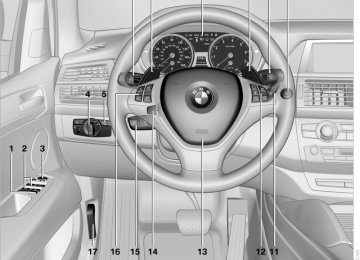
1 High beams 2 Headlamp flasher 3 Turn signal Signaling a turn Press the lever beyond the resistance point. To switch off manually, press the lever to the re‐ sistance point. Unusually rapid flashing of the indicator lamp in‐ dicates that a turn signal bulb has failed. Signaling a turn briefly Press the lever to the resistance point and hold it there for as long as you want the turn signal to flash. Triple turn signal activation Press the lever to the resistance point. The turn signal flashes three times. This function can be activated or deactivated: 1. "Settings" 2. "Lighting" 3. "Triple turn signal"
66
Online Edition for Part no. 01 40 2 606 735 - 03 11 500
The setting is stored for the remote control cur‐ rently in use.
Washer/wiper system
Do not switch on the wipers if frozen Do not switch on the wipers if they are fro‐
zen onto the windshield; otherwise, the wiper blades and the windshield wiper motor may be damaged.◀
The lever automatically returns to its initial po‐ sition when released. ▷ Brief wipe: press down once. ▷ To switch off normal wipe: press down once. ▷ To switch off fast wipe: press down twice. Rain sensor If the car is equipped with a rain sensor, the time between wipes is controlled automatically and depends on the intensity of the rainfall. The rain sensor is mounted on the windshield, directly in front of the interior rearview mirror. Activating the rain sensor
1 Switching on wipers 2 Switching off wipers or brief wipe 3 Activating/deactivating the rain sensor 4 Cleaning the windshield and headlamps* 5 Setting the sensitivity of the rain sensor Switching on wipers Press the wiper lever upward, arrow 1. The lever automatically returns to its initial po‐ sition when released. Normal wiper speed Press up once. The system switches to operation in the inter‐ mittent mode when the vehicle is stationary. Fast wiper speed Press up twice or press once beyond the resist‐ ance point. The system switches to normal speed when the vehicle is stationary. Switching off wipers or brief wipe Press the wiper lever down, arrow 2.
Press the button, arrow 3. The LED in the button lights up.
Rain sensor sensitivity Turn thumbwheel 5 up or down. Deactivating the rain sensor Press the button again, arrow 3. The LED goes out.
Deactivate the rain sensor in car washes Deactivate the rain sensor when passing through an automatic car wash; otherwise, dam‐ age could be caused by undesired wiper activa‐ tion.◀
Cleaning the windshield and headlamps* Pull the lever, arrow 4. The system sprays washer fluid on the wind‐ shield and activates the wipers briefly.
Online Edition for Part no. 01 40 2 606 735 - 03 11 500
67
g
When the vehicle lighting system is switched on, the headlamps are cleaned at regular and ap‐ propriate intervals.
Do not use the washer system at freezing temperatures
Do not use the washers if there is any danger that the fluid will freeze on the windshield; oth‐ erwise, your vision could be obscured. For this reason, use antifreeze. Avoid using the washer when the reservoir is empty; otherwise, you could damage the pump.◀
Windshield washer nozzles The windshield washer nozzles are heated au‐ tomatically while the engine is running or the ig‐ nition is switched on. BMW X5: rear window wiper
Washer fluid General information
Antifreeze for washer fluid Antifreeze is flammable. Therefore, keep
it away from sources of ignition. Only keep it in the closed original container and inaccessible to children. Follow the instructions on the container.◀
Washer fluid reservoir Adding washer fluid Only add washer fluid when the engine is
cool, and then close the cover completely to avoid contact between the washer fluid and hot engine parts. Otherwise, there is the danger of fire and a risk to personal safety if the fluid is spilled.◀
1 Intermittent wipe
When reverse gear is engaged, the system switches to continuous operation.
2 Cleaning the rear window
Do not use the washing mechanisms when the washer fluid reservoir is empty
Do not use washing mechanisms when the washer fluid reservoir is empty, otherwise you will damage the washer pump.◀
All washer nozzles are supplied from one reser‐ voir. Fill with water and – if required – with a washer antifreeze, according to the manufacturer's rec‐ ommendations. Mix the washer fluid before adding to maintain the correct mixing ratio. Capacity Approx. 6.3 US quarts/6 liters.
68
Online Edition for Part no. 01 40 2 606 735 - 03 11 500
Automatic transmission with Steptronic Transmission positions D Drive, automatic position Position for normal vehicle operation. All for‐ ward gears are available. Under normal operating conditions, fuel con‐ sumption is lowest when you are driving in po‐ sition D.
Kickdown Kickdown is used to achieve maximum driving performance. Press on the accelerator beyond the resistance point at the full throttle position. R is Reverse Select only when the vehicle is stationary. N is Neutral Use in automatic car washes, for example. The vehicle can roll. When the ignition is switched off, refer to page 61, position P is engaged automatically. P Park Select only when the vehicle is stationary. The drive wheels are blocked. P is engaged automatically as soon as the en‐ gine is switched off unless N is engaged and, in vehicles with Comfort Access, the remote con‐ trol is inserted in the ignition lock, refer to page 61. Before leaving the vehicle, ensure that the transmission position P is engaged; other‐ wise, the vehicle may begin to roll. Engaging transmission position ▷ Transmission position P can only be disen‐ gaged if the engine is running and the brake pedal is pressed.
▷ With the vehicle stationary, press on the brake pedal before shifting out of P or N; otherwise, the shift command will not be executed: shift lock.
Press on the brake pedal until you start driving
To prevent the vehicle from creeping after you select a driving position, maintain pressure on the brake pedal until you are ready to start.◀
Shifting into D, R, N
Briefly push the selector lever in the desired di‐ rection, beyond a resistance point if necessary. When shifting out of P or into R, simultaneously push the unlock button 1. The engaged transmission position is displayed on the selector lever. After releasing the selector lever, it returns to its center position.
Engaging P
Press button P. P is engaged if the driver's safety belt is unbuck‐ led and the driver's door is opened while the ve‐ hicle is stationary and transmission position R or D is engaged. Before leaving the vehicle, ensure that the transmission position P is engaged; oth‐ erwise, the vehicle may begin to roll.
Online Edition for Part no. 01 40 2 606 735 - 03 11 500
69
Sport program and manual mode M/S Activating the sport program
Push the selector lever to the left out of trans‐ mission position D. The Sport program is activated and DS is dis‐ played in the instrument cluster; in the BMW X6, S4 is displayed, for example. This position is recommended for a perform‐ ance-oriented driving style. Activating the M/S manual mode Push the selector lever to the left out of trans‐ mission position D. Push the selector lever forward or backward. Manual mode becomes active and the gear is changed. The engaged gear is displayed in the instrument cluster, e.g., M1. ▷ To shift down: press the selector lever for‐
ward.
▷ To shift up: press the selector lever back‐
ward.
The transmission only shifts up or down if the rpm and vehicle speed are appropriate. If the engine speed is too high, the transmission does not shift down. The selected gear is briefly displayed in the in‐ strument panel, followed by the current gear. Ending the sport program/manual mode Push the selector lever to the right. D is displayed in the instrument cluster.
BMW X6: Gear change using the shift paddles on the steering wheel The shifting paddles make it possible to quickly change gears since both hands can remain on the steering wheel. ▷ If the shift paddles on the steering wheel are used to shift gears while in automatic mode D, the transmission temporarily switches to manual mode.
▷ If the shift paddles are not used to accelerate or shift gears for a certain amount of time, the transmission switches back to auto‐ matic mode D.
With the transmission position M/S selected, the manual mode remains active.
▷ Shift up: pull right shift paddle. ▷ Shift down: pull left shift paddle. The vehicle only shifts up or down at appropriate engine and road speeds, e.g., it does not shift down if the engine speed is too high. The selected gear is briefly displayed in the in‐ strument cluster, followed by the current gear. Displays in the instrument cluster
The gear position is displayed and the engaged gear, such as M4, is displayed in manual mode.
70
Online Edition for Part no. 01 40 2 606 735 - 03 11 500
Displays Odometer, external temperature display, clock
Retrieving date
1 Knob in the instrument cluster 2 Time, external temperature, and date 3 Odometer and trip odometer Knob in the instrument cluster Press the knob. ▷ When the ignition is switched on, the trip
odometer is reset. Press the knob for approx. 5 seconds: View service requirement display, refer to page 75
▷ When the ignition is switched off, the time, external temperature and odometer are dis‐ played.
Units of measure To set the respective units of measure, miles or km for the odometer and ℃ or ℉ for the external temperature, refer to page 80. The setting is stored for the remote control cur‐ rently in use. Time, date, external temperature From radio readiness the external temperature and the time are displayed. Set the time, refer to page 79.
Press the button on turn signal lever upward; the date appears. Set the date, refer to page 79. Pressing the button upward or downward sev‐ eral times changes the display between clock, external temperature, date, and Check Control messages, refer to page 76. External temperature warning If the display drops to +37 ℉/+3 ℃, a signal sounds and a warning lamp lights up. There is the increased danger of ice.
Ice on roads Even at temperatures above +37 ℉/+3 ℃,
there can be a risk of ice on roads. Therefore, drive carefully on bridges and shady roads, for example, to avoid the increased dan‐ ger of an accident.◀
Odometer and trip odometer Resetting trip odometer: With the ignition switched on, press button 1 in the instrument cluster. When the vehicle is parked If you still want to view the time, external tem‐ perature and odometer reading briefly after the remote control has been taken out of the ignition lock: Press button 1 in the instrument cluster.
Online Edition for Part no. 01 40 2 606 735 - 03 11 500
71
Tachometer
Current fuel consumption*
Never force the engine speed up into the red warning field, see arrow. In this range, the fuel supply is interrupted to protect the engine.
Coolant temperature A warning lamp will come on if the coolant, and therefore the engine, becomes too hot. In addi‐ tion, a message will appear on the Control Dis‐ play. Check the coolant level, refer to page 267.
Displays the current fuel consumption. You can check whether you are currently driving in an ef‐ ficient and environmentally-friendly manner.
Engine oil temperature*
▷ Cold engine: the pointer is at the low tem‐ perature end. Drive at moderate engine and vehicle speeds.
▷ Normal operating temperature: the pointer is in the middle or in the right half of the tem‐ perature display.
▷ Hot engine: the pointer is at the high tem‐ perature end. Switch off the engine imme‐ diately and allow it to cool down.
If the engine oil temperature is too high, a mes‐ sage appears on the Control Display. Check the oil level, refer to page 265.
72
Online Edition for Part no. 01 40 2 606 735 - 03 11 500
Fuel gauge
Computer Displaying information on the instrument panel
The vehicle inclination may cause the display to vary. Notes on refueling, refer to page 246. Reserve After the reserve range is reached: ▷ A message is briefly displayed on the Con‐
trol Display.
▷ The remaining range is shown on the com‐
puter.
▷ When a dynamic driving style is used, such as when corners are taken rapidly, engine functions are not ensured.
The message appears continuously below a range of approx. 30 miles/50 km.
Refuel promptly At the latest, refuel when the range drops below 30 miles/50 km; otherwise, engine func‐ tions are not ensured and damage may occur.◀
Press the computer button on the turn signal lever. Information is displayed in the instrument clus‐ ter. Overview of the information Repeatedly pressing the button on the turn sig‐ nal lever displays the information on the instru‐ ment cluster in the following order: ▷ Range. ▷ Average speed*. ▷ Average fuel consumption. To set the corresponding units of measure, refer to page 80. Information in detail Range Displays the estimated cruising range available with the remaining fuel. It is calculated based on your driving style over the last 18 miles/30 km. Average speed Periods in which the vehicle is parked with the engine stopped do not enter into the calculation. With the trip computer, refer to page 74, you can have the average speed displayed for an ad‐ ditional distance. To reset the average speed: press the button on the turn indicator lever for approx. 2 seconds.
Online Edition for Part no. 01 40 2 606 735 - 03 11 500
73
l
Average fuel consumption This is calculated for the period during which the engine is running. You can have the average consumption for an‐ other trip displayed, refer to Displays on the Control Display below. To reset the average consumption: press the button on the turn indicator lever for ap‐ prox. 2 seconds. Displays on the Control Display Display the computer or trip computer on the Control Display. 1. "Vehicle Info" 2. "Onboard info" or "Trip computer"
Displays on the "Onboard info":
▷ Range. ▷ Distance to destination. ▷ Estimated time of arrival if a destination was entered in the navigation system*, refer to page 153.
Displays on the "Trip computer":
▷ Departure time. ▷ Trip duration. ▷ Trip distance. Both displays show: ▷ Average fuel consumption and ▷ Average speed. Resetting the fuel consumption and speed Resetting the values for average speed and average fuel consumption: 1. Select the respective menu item and press
the controller.
2. Press the controller again to confirm your
selection.
Resetting the trip computer Resetting all values: 1. "Vehicle Info" 2. "Trip computer" 3. "Reset"
74
Online Edition for Part no. 01 40 2 606 735 - 03 11 500
Service requirements
Displays
Symbol
The remaining driving distance and the date of the next scheduled service are displayed briefly immediately after you start the engine or switch on the ignition. The current service requirements can be read out from the remote control by the service spe‐ cialist. For certain maintenance operations, you can view the distance remaining or the due date for that operation in the instrument cluster.
1. With the ignition switched on, press the knob in the instrument cluster, refer to page 71, for approx. 5 seconds until the service requirements are displayed.
2. Press the knob repeatedly to display the in‐
dividual service requirement items.
Function Service requirements
Engine oil
Roadworthiness test*
Front brake pads
Rear brake pads
Brake fluid
The sequence of displayed service items may vary. First the data for the next maintenance are displayed. Detailed information on service requirements More information on the scope of service re‐ quired can be displayed on the Control Display. 1. "Vehicle Info"
Online Edition for Part no. 01 40 2 606 735 - 03 11 500
75
2. "Vehicle status"
4. "§ Vehicle inspection"
"Service required"
3. Required maintenance procedures and legally mandated inspections are displayed. Additional information can be displayed on each entry: Select the entry and press the controller. To exit from the menu: Move the controller to the left. Symbols
Symbols
Description No service is currently required.
The deadline for service or a le‐ gally mandated inspection is approaching. Please make a service appointment. The service deadline has al‐ ready passed.
Entering dates* Enter the dates for the required inspections. Make sure the date on the Control Display is set correctly, refer to page 79. 1. "Vehicle Info" 2. "Vehicle status" 3.
"Service required"
5. Open the menu for entering the deadline. 6. "Date:" 7. Create the settings. 8. Press the controller to apply the setting. The
year is highlighted.
9. Turn the controller to make the adjustment. 10. Press the controller to apply the setting. The
date entry is stored. To exit from the menu: Move the controller to the left. Automatic Service Request* Data regarding the maintenance status or legally mandated inspections of the vehicle are auto‐ matically transmitted to your service center be‐ fore a service due date. You can check when your service center was notified. 1. "Vehicle Info" 2. "Vehicle status" 3. Open "Options". 4. "Last Service Request"
Check Control The concept The Check Control monitors vehicle functions and alerts you to any malfunctions in the sys‐ tems monitored. A Check Control message consists of indicator and warning lamps in the instrument cluster and,
76
Online Edition for Part no. 01 40 2 606 735 - 03 11 500
in some circumstances, an acoustic signal and text messages at the top of the Control Display. Indicator/warning lamps
Symbols The following functions can be selected within the supplementary text message, depending on the Check Control message. ▷
"Service request"
Contact the service partner. "Roadside Assistance"
▷
Contact Roadside Assistance.
Hiding Check Control messages
The indicator and warning lamps can light up in a variety of combinations and colors. Several of the lamps are checked for proper functioning and light up temporarily when the engine is started or the ignition is switched on.
The symbol indicates that Check Control
messages have been stored. The Check Control messages can be displayed later.
Text messages Text messages at the upper edge of the Control Display in combination with a symbol in the in‐ strument cluster explain a Check Control mes‐ sage and the meaning of the indicator and warn‐ ing lamps. Supplementary text messages Addition information, such as on the cause of a fault or the required action, can be called up via Check Control. In urgent cases, this information will be shown as soon as the corresponding lamp comes on.
Press the button in the turn signal lever up or down. ▷ Some Check Control messages are dis‐
played continuously and are not cleared un‐ til the malfunction is eliminated. If several malfunctions occur at once, the messages are displayed consecutively. These messages can be hidden for approx. 8 seconds. After this time, they are dis‐ played again automatically.
▷ Other Check Control messages are hidden
automatically after approx. 20 seconds. They are stored and can be displayed again later.
Viewing stored Check Control messages
Online Edition for Part no. 01 40 2 606 735 - 03 11 500
77
l
1. Press the button on the turn signal lever downward. "CHECK OK" or the stored Check Control messages appear on the dis‐ play. „CHECK OK“ is shown if no messages are present. Check Control messages are accompanied by text messages on the Control Display.
2. Press the button to display additional mes‐ sages, the time and external temperature, or the date.
Displaying stored Check Control messages 1. "Vehicle Info" 2. "Vehicle status" 3. 4. Select the text message. Messages after trip completion Malfunctions indicated during a trip are dis‐ played again after the ignition is switched off.
"Check Control"
Speed limit* Entry of a speed limit which, when reached, should cause a Check Control message to be issued. Renewed warning if the vehicle speed drops be‐ low the set speed limit once by at least 3 mph/ 5 km/h. Displaying, setting or changing the limit 1. "Settings" 2. "Speed"
3. "Warning at:"
4. Turn the controller until the desired limit is
displayed.
5. Press the controller. The speed limit is stored. Applying your current speed as the limit 1. "Settings" 2. "Speed" 3. "Select current speed" The system adopts your current speed as the limit. Activating/deactivating the limit 1. "Settings" 2. "Speed" 3. "Warning"
Settings on the Control Display Time The settings are stored for the remote control currently in use.
78
Online Edition for Part no. 01 40 2 606 735 - 03 11 500
Setting the time zone* 1. "Settings" 2. "Time/Date"
3. "Time zone:" 4. Select the desired time zone. The time zone is stored. Setting the time 1. "Settings"
2. "Time/Date" 3. "Time:"
6. Turn the controller until the desired minutes
are displayed.
7. Press the controller. The time is stored. Setting the time format 1. "Settings" 2. "Time/Date" 3. "Format:" 4. Select the desired format. The time format is stored. Date The settings are stored for the remote control currently in use. Setting the date 1. "Settings" 2. "Time/Date" 3. "Date:" 4. Turn the controller until the desired day is
displayed.
5. Press the controller. 6. Make the necessary settings for the month
and year.
The date is stored. Setting the date format 1. "Settings" 2. "Time/Date" 3. "Format:" 4. Select the desired format.
4. Turn the controller until the desired hours
are displayed.
5. Press the controller.
The date format is stored.
79
Online Edition for Part no. 01 40 2 606 735 - 03 11 500
l
Language Setting the language To set the language on the Control Display: 1. "Settings" 2. "Language/Units" 3. "Language:"
1. "Settings" 2. "Language/Units"
3. Select the desired menu item. 4. Select the desired unit. The setting is stored for the remote control cur‐ rently in use. Brightness Setting the brightness To set the brightness of the Control Display: 1. "Settings" 2. "Control display" 3. "Brightness"
4. Select the desired language. The setting is stored for the remote control cur‐ rently in use. Setting the voice dialog To switch between a standard dialog and a short dialog. 1. "Settings" 2. "Language/Units" 3. "Speech mode" 4. Select the desired dialog.
4. Turn the controller until the desired bright‐
ness is set.
5. Press the controller. The setting is stored for the remote control cur‐ rently in use. Depending on the light conditions, the bright‐ ness control may not be clearly visible.
Units of measure Setting the units of measure To set the units for fuel consumption, route/dis‐ tance, temperature, and pressure:
80
Online Edition for Part no. 01 40 2 606 735 - 03 11 500
or
Welcome lamps When parking the vehicle, leave the switch in position : the parking and interior lamps light up briefly when the vehicle is un‐ locked. Activating/deactivating the welcome lamps 1. "Settings" 2. "Lighting" 3. "Welcome light"
The setting is stored for the remote control cur‐ rently in use. Headlamp courtesy delay feature The low beams stay lit for a short while after the ignition is switched off, if the lamps are switched off and the headlamp flasher is switched on. Setting the duration 1. "Settings" 2. "Lighting"
Lamps At a glance
0 Lamps off and daytime running lights* 1 Parking lamps and daytime running lights* 2 Low-beam headlamps and welcome lamps 3 Automatic headlamp control*, daytime run‐ ning lights*, welcome lamps, adaptive light control* and High-beam Assistant*
: the vehicle lamps light
Parking lamps/low beams, headlamp control* Parking lamps Switch position up on all sides, e.g., for parking. Do not use the parking lamps for extended pe‐ riods; otherwise, the battery may become dis‐ charged and it would then be impossible to start the engine. When parking, it is preferable to switch on the one-sided roadside parking lamps, refer to page 83. When the driver's door is opened with the igni‐ tion switched off: the exterior lighting is auto‐ matically switched off when the light switch is in position 0, 2 or 3. Switch on the parking lamps if necessary, switch position 1. Low beams Switch position on: the low beams light up.
with the ignition switched
Online Edition for Part no. 01 40 2 606 735 - 03 11 500
81
3. "Pathway light.: s"
3. "Daytime running lamps"
4. Set the duration. The setting is stored for the remote control cur‐ rently in use. Automatic headlamp control* Switch position : the low beams are switched on and off automatically, e.g., in tunnels, in twi‐ light or if there is precipitation. The LED next to the symbol lights up. A blue sky with the sun low on the horizon can cause the lights to be switched on. The low beams remain switched on independ‐ ent of the ambient lighting conditions when you switch on the front fog lamps*.
Personal responsibility The automatic headlamp control cannot serve as a substitute for your personal judgment in determining when the lamps should be switched on in response to ambient lighting conditions. For example, the sensors are unable to detect fog or hazy weather. To avoid safety risks, you should always switch on the lamps manually un‐ der these conditions.◀
and
Daytime running lights The daytime running lights light up in posi‐ tion 0, . After the ignition is switched off, the parking lamps light up in posi‐ tion Activating/deactivating 1. "Settings" 2. "Lighting"
The setting is stored for the remote control cur‐ rently in use.
Adaptive light control* The concept Adaptive light control is a variable headlamp control system that enables dynamic illumina‐ tion of the road surface. Depending on the steering angle and other pa‐ rameters, the light from the headlamp follows the course of the road. In sharp curves, e.g. serpentines, or during turn‐ ing, up to a certain speed one of the two front fog lamps* is switched on as a turning lamp. This provides improved illumination of the area inside the curve. Controls Activating Switch position on. The turning lamps are automatically switched on depending on the steering angle or the use of turn signals. Standstill function*: to avoid blinding oncoming traffic, the Adaptive Light Control directs light towards the front passenger side when the ve‐ hicle is at a standstill. When driving in reverse, both turning lamps are active.
with the ignition switched
82
Online Edition for Part no. 01 40 2 606 735 - 03 11 500
Malfunction A message is displayed. Adaptive light control is malfunctioning or has failed. Have the system checked as soon as pos‐ sible.
High beams/roadside parking lamps
1 High beams 2 Headlamp flasher 3 Roadside parking lamps* Left and right roadside parking lamps* The vehicle can be illuminated on one side. Switching on After parking the vehicle, press the lever up or down beyond the resistance point for ap‐ prox. 2 seconds, arrow 3. The roadside parking lamps drain the battery. Therefore, do not leave them on for unduly long periods of time; otherwise, the battery might not have enough power to start the engine. Switching off Briefly press the lever in the opposite direction to the pressure point, arrow 3.
High-beam Assistant* The concept When the lights are switched on, this system automatically switches the high beams on and off. The procedure is controlled by a sensor on
the front of the interior rearview mirror. The as‐ sistant ensures that the high beams are switched on whenever the traffic situation al‐ lows. The driver can intervene at any time and switch the high beams on and off as usual. Activating the High-beam Assistant 1. Turn the light switch to 2. With the low beams switched on, briefly
push the turn indicator lever in the direction of the high beam.
The indicator lamp in the instrument cluster lights up. The high beams are switched on and off automatically.
The system responds to light from oncoming traffic and traffic driving ahead of you, and to ad‐ equate illumination, e.g., in towns and cities. Switching the high beams on and off manually
▷ High beams on, arrow 1. ▷ High beams off/headlamp flasher, arrow 2. To reactivate the High-beam Assistant, briefly push the turn indicator lever toward the high beams.
Online Edition for Part no. 01 40 2 606 735 - 03 11 500
83
s
Activating/deactivating via iDrive 1. "Settings" 2. "Lighting" 3. "High beam assistant"
The setting is stored for the remote control cur‐ rently in use. System limits
Personal responsibility The High-beam Assistant cannot serve as a substitute for the driver's personal judgment of when to use the high beams. Therefore, man‐ ually switch off the high beams in situations where this is required to avoid a safety risk.◀ The system is not fully functional in situations such as the following, and driver intervention may be necessary: ▷ In very unfavorable weather conditions,
such as fog or heavy precipitation.
▷ In detecting poorly-lit road users, such as pedestrians, cyclists, horseback riders and wagons; when driving close to train or ship traffic; and at animal crossings.
▷ In tight curves, on hilltops or in depressions, in cross traffic or half-obscured oncoming traffic on freeways.
▷ In poorly-lit towns and cities and in the pres‐
ence of highly reflective signs.
▷ At low speeds. ▷ When the windshield in front of the interior rearview mirror is fogged over, dirty or cov‐ ered with stickers, etc.
▷ If the sensor view field is dirty.
The view field of the sensor is located on the front of the interior rearview mirror. Do not cover this area with stickers, etc. Clean the sensor view field with a cloth mois‐ tened with a small amount of glass cleaner.
Front fog lamps* The parking lamps or low beams must be switched on.
Press the button. The green indicator lamp in the instrument cluster lights up.
If the automatic headlamp control, refer to page 82, is activated, the low beams will come on automatically when you switch on the fog lamps.
Instrument lighting
Adjust the brightness using the thumbwheel.
Interior lamps General information The interior lamps, footwell lamps*, exit lamps*, cargo area lamps and courtesy lamps* are con‐ trolled automatically. The courtesy lamps* have LED lights in the door handles to illuminate the exterior area in front of the doors. To avoid draining the battery, all lamps inside the car are switched off about 8 minutes after the ignition is switched off, Start/Stop button, refer to page 61.
84
Online Edition for Part no. 01 40 2 606 735 - 03 11 500
Switching the interior lamps on and off
Press the button. To switch off permanently: press the button for approx. 3 seconds. To clear this setting: briefly press the button. Reading lamps
Press the button. Reading lamps are located at the front and rear* next to the interior lamps.
Online Edition for Part no. 01 40 2 606 735 - 03 11 500
85
Safety Airbags
1 Front airbags 2 Head airbags 3 Side airbags
Front airbags Front airbags help protect the driver and front passenger by responding to frontal impacts in which safety belts alone cannot provide ade‐ quate restraint. Side airbags In a lateral impact, the side airbag supports the side of the body in the chest and lap area. Head airbags In a lateral impact, the head airbag supports the head. Protective action Airbags are not triggered in every impact situa‐ tion, e.g., in less severe accidents or rear-end collisions.
Information on how to ensure the optimal protective effect of the airbags
▷ Keep at a distance from the airbags. ▷ Always grasp the steering wheel on the
steering wheel rim, holding your hands at the 3 o'clock and 9 o'clock positions, to keep the danger of injury to your hands or arms as low as possible if the airbag is triggered.
▷ There should be no people, animals, or ob‐
jects between an airbag and a person.
▷ Do not use the cover of the front airbag on the front passenger side as a storage area.
▷ Keep the dashboard and window on the
front passenger side clear, i.e., do not cover with adhesive labels or coverings, and do not attach holders such as for navigation instru‐ ments and mobile phones.
▷ Make sure that the front passenger is sitting correctly, i.e., keeps his or her feet and legs in the footwell; otherwise, leg injuries can occur if the front airbag is triggered.
▷ Do not place slip covers, seat cushions or other objects on the front passenger seat that are not approved specifically for seats with integrated side airbags.
▷ Do not hang pieces of clothing, such as jack‐
ets, over the backrests.
▷ Make sure that occupants keep their heads
away from the side airbag and do not rest against the head airbag; otherwise, injuries can occur if the airbags are triggered.
▷ Do not remove the airbag restraint system. ▷ Do not remove the steering wheel.
86
Online Edition for Part no. 01 40 2 606 735 - 03 11 500
Leave feet in the footwell Make sure that the front passenger keeps his or her feet in the footwell; otherwise, the front passenger airbags may not function properly.◀
Child restraint fixing system in the front passenger seat
Before transporting a child on the front passen‐ ger seat, refer to the safety notes and instruc‐ tions under Children on the front passenger seat, refer to page 56.◀
Malfunction of the automatic deactivation system When transporting older children and adults, the front passenger airbags may be deactivated in certain sitting positions. In this case, the indica‐ tor lamp for the front passenger airbags lights up. In this case, change the sitting position so that the front passenger airbags are activated and the indicator lamp goes out. If it is not possible to activate the airbags, have the person sit in the rear. To make sure that occupation of the seat cush‐ ion can be detected correctly: ▷ Do not attach seat covers, seat cushion pad‐ ding, ball mats or other items to the passen‐ ger seat unless they are specifically recom‐ mended by BMW.
▷ Do not place objects under the seat that could press against the seat from below. Indicator lamp for the front passenger airbags
▷ Do not apply adhesive materials to the air‐