- Download PDF Manual
-
Turn toward front
▷ Distributing air in storage compartment
area between seats: Turn toward rear
2 Button for switching on the blower: LED is lit The heating is not ready for operation without switching on the blower. After the heating is switched off, the blower can be used to recircu‐ late the air within the vehicle, for instance at high temperatures. To do this, turn thumbwheel 1 to‐ ward the rear and switch on the blower, button 2. Microfilter/activated-charcoal filter The microfilter traps dust and pollen in the in‐ coming air. The activated-charcoal filter removes gaseous pollutants from the outside air that enters the vehicle. The service center replaces this combined filter during routine maintenance. More information can be found in the service re‐ quirements display, refer to page 75.
Automatic climate control with 4-zone control* Front operation Corresponds to the operation of automatic cli‐ mate control with 2-zone control, refer to page 120. Rear operation The control unit is located in the center console in the rear.
1 Temperature, left rear seating area 2 AUTO program 3 Display 4 Temperature, right rear seating area 5 Seat heating, right rear seat 6 Air volume, manual 7 Seat heating, left rear seat The current setting for the temperature and the air flow rate is shown on display 3. Activation/deactivation 1. "Settings" 2. "Climate" 3. "Rear climate control" 4. Select the desired settings.
The rear automatic climate control cannot be operated if the front automatic climate control is switched off. With the defrost windows and eliminate condensation function activated, the rear automatic climate control is also not ready for operation.
124
Online Edition for Part no. 01 40 2 606 735 - 03 11 500
AUTO program
Ventilation in rear
The AUTO program automatically sets the air distribution toward the upper body and in the footwell, as well as the air flow rate. It also adapts your instructions for the
temperature to outside influences throughout the year.
Temperature
Set the desired temperature indi‐ vidually on the left and right side.
The automatic climate control achieves this temperature as quickly as possible regardless of the season, using maximum cooling or heating power if necessary, and then maintains it. When switching between different temperature settings in rapid succession, the automatic cli‐ mate control does not have sufficient time to adjust the set temperature. Air volume, manual
The air flow rate can be varied by press‐ ing on the corresponding side. The au‐
tomatic mode for the air flow rate can be switched on again using the AUTO button.
Switching off rear automatic climate control
With the blower at its lowest setting, press the left side of the button to
switch off the automatic climate control. The automatic climate control can also be switched off with iDrive. To switch on the auto‐ matic climate control again, the system must first be reactivated, refer to Activating/deacti‐ vating. The system is switched on again by pressing any button of the rear automatic climate control.
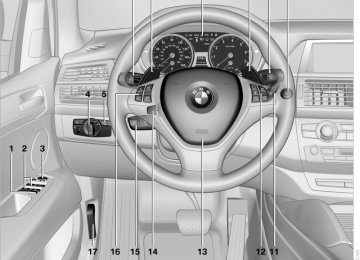
1 Use the thumbwheels to smoothly open and
close the air vents
2 Thumbwheels to adjust temperature in up‐ per body region; can be adjusted separately for left and right: ▷ Blue: colder ▷ Red: warmer
3 Use the lever to change the direction of the
air flow BMW X5
1 Use the lever to change the direction of the
2 Thumbwheel to smoothly open and close air
air flow
vents
For ventilation of the 3rd row seats, refer to page 123.
Parked-car ventilation* The concept The parked-car ventilation blows air into the passenger compartment to lower interior tem‐ peratures.
Online Edition for Part no. 01 40 2 606 735 - 03 11 500
125
The symbol on the automatic climate control flashes when the system has been switched on. The system will only be switched on within the next 24 hours. After that, it needs to reactivated.
The system can be switched on and off at any external temperature, either directly or by using a preset switch-on time. It remains switched on for 30 minutes. Since the system uses a substantial amount of electrical current, refrain from activating it twice in succession without allowing the battery to be recharged in normal operation between use. Open the vents to allow air to flow out. They can be operated via iDrive. Switching on/off directly 1. "Settings" 2. "Climate" 3. "Activate parked-car vent."
The symbol on the automatic climate control
flashes if the system is switched on. Preselecting activation times 1. "Settings" 2. "Climate" 3. "Activate Timer 1" or "Activate Timer 2" 4. "Timer 1:" or "Timer 2:"
5. Set the desired time.
The symbol on the automatic climate control lights up when the switch-on time is activated.
126
Online Edition for Part no. 01 40 2 606 735 - 03 11 500
Interior equipment Integrated universal remote control* The concept This system can replace up to three different hand-held transmitters for various types of re‐ mote-controlled equipment, such as garage doors or lighting systems. The hand-held transmitter signal can be pro‐ grammed on one of the three memory buttons. The corresponding device can then be operated using the programmed memory button. The LED indicates that a signal is being trans‐ mitted. When selling the vehicle, delete the stored pro‐ grams for security reasons. During programming During programming and before activat‐ ing a device using the integrated universal re‐ mote control, ensure that there are no people, animals or objects in the range of movement of the remote-controlled device; otherwise, there is a risk of injury or damage. Also follow the safety instructions of the hand- held transmitter.◀
Compatibility
If this symbol is printed on the packaging or in the instructions of the hand-held transmitter, the remote-controlled de‐ vice is generally compatible with the universal remote control. If you have any questions, please contact: ▷ Your service center. ▷ www.homelink.com on the Internet.
Programming
1 Memory buttons 2 LED Fixed-code hand-held transmitters 1. Switch on the ignition, refer to page 61. 2.
Initial setup: Press both outer memory buttons 1 for ap‐ prox. 20 seconds until the LED flashes. All programs of the three memory buttons 1
are cleared.3. Hold the hand-held transmitter at a distance
of approx. 1 to 3 in/2.5 to 8 cm from the memory buttons. The required distance depends on the par‐ ticular hand-held transmitter.
4. Simultaneously press the transmit button of the hand-held transmitter and the memory button of the integrated universal remote control. The LED flashes slowly.
5. Release both buttons when the LED flashes
rapidly. If the LED does not flash rapidly after approx. 60 seconds, change the distance and repeat the step. Canada: if the LED does not flash rapidly af‐ ter approx. 60 seconds, change the distance and repeat the step. If programming was aborted by the hand-held transmitter, hold down the memory button and press and re‐
Online Edition for Part no. 01 40 2 606 735 - 03 11 500
127
i
lease the button on the hand-held transmit‐ ter several times for 2 seconds.
6. To program additional hand-held transmit‐
ters, repeat steps 3 to 5.
The device can be operated using the memory button with the engine running or the ignition switched on. Malfunction If the device cannot be used after repeated at‐ tempts at programming, please check whether the hand-held transmitter is equipped with an alternating code system. To do so: ▷ Read the instructions of the hand-held
transmitter.
▷ Press the memory button of the universal
remote control for an extended period.
If the LED of the integrated universal remote control flashes quickly for a short period and then lights up continuously, the hand-held transmitter is equipped with an alternating code system. In this case, program the memory buttons as described under Alternating-code hand-held transmitters. Alternating-code hand-held transmitters Please obtain information on synchronizing the device in the operating manual of the device be‐ ing set up. Programming will be easier with the aid of a sec‐ ond person. 1. Park the vehicle within range of the remote-
controlled device.
2. Program the integrated universal remote control as described above under Fixed- code hand-held transmitters.
3. Locate the button on the receiver of the de‐
vice to be set, e.g., on the drive.
4. Press the button on the receiver of the de‐ vice to be set. You have approx. 30 seconds for the next step.
5. Press the programmed memory button of the integrated universal remote control for approx. 3 seconds. Repeat this step up to three times if necessary.
The device can be operated using the memory button with the engine running or the ignition switched on. Reassigning individual programs 1. Switch on the ignition. 2. Hold the hand-held transmitter at a distance
of approx. 1 to 3 in/2.5 to 8 cm from the memory buttons. The required distance depends on the par‐ ticular hand-held transmitter.
3. Press the memory button of the integrated
4.
universal remote control. If the LED flashes slowly after approx. 20 seconds, press the transmit button on the hand-held transmitter.
5. Release both buttons when the LED flashes
rapidly. If the LED does not flash rapidly after approx. 60 seconds, change the distance and repeat the step. Canada: if the LED does not flash rapidly af‐ ter approx. 60 seconds, change the distance and repeat the step. If programming was aborted by the hand-held transmitter, hold down the memory button and press and re‐ lease the button on the hand-held transmit‐ ter several times for 2 seconds. Deleting all stored programs Press both outer memory buttons 1 for ap‐ prox. 20 seconds until the LED flashes rapidly. All stored programs are deleted. The programs cannot be deleted individually.
128
Online Edition for Part no. 01 40 2 606 735 - 03 11 500
Digital compass*
1 Adjustment button 2 Display The display shows you the main or secondary compass direction in which you are driving. Setting compass zones Set the compass zone corresponding to the ve‐ hicle's geographic location so that the compass
Operating concept Various functions can be called up by pressing the adjustment button with a pointed object such as a pen. The following adjustment options are displayed one after the other, depending on how long the adjustment button is pressed: ▷ Press briefly: switch the display on/off. ▷ 3 to 6 seconds: set the compass zone. ▷ 6 to 9 seconds: calibrate the compass. ▷ 9 to 12 seconds: set left-hand/right hand
steering.
▷ 12 to 15 seconds: set the language.
can function correctly; refer to the world map with compass zones.
Press the adjustment button for 3‑4 seconds. The number of the compass zone set is shown in the display. To change the zone setting, briefly press the adjustment button repeatedly until the display shows the number of the compass zone corre‐ sponding to the current location.
The compass is operational again after approx. 10 seconds. Calibrating the digital compass The digital compass must be calibrated in the following situations: ▷ An incorrect compass direction is shown.
Online Edition for Part no. 01 40 2 606 735 - 03 11 500
129
i
▷ The cardinal direction displayed does not
change even if the direction of travel changes.
▷ Not all compass directions are shown. Procedure 1. Make sure that there are no large metal ob‐ jects or overhead power lines in the vicinity of the vehicle and that there is enough space to drive in a circle.
2. Set the currently valid compass zone. 3. Press the adjustment button for 6‑7 sec‐
onds to call up C. Then drive at least one full circle at a maximum speed of 4 mph/7 km/h. When the system is calibrated, the C is re‐ placed by the compass directions. Right-hand/left-hand steering The digital compass is set for right-hand or left- hand steering at the factory. Setting the language Press the adjustment button for 12‑13 seconds. Briefly press the adjustment button again to switch between English "E" and German "O". The setting is automatically saved after approx. 10 seconds.
Ashtray/cigarette lighter* Opening Front
Rear BMW X6
Slide the cover back.
Emptying Take out the insert. Lighter
With the engine running or the ignition switched on, press in the cigarette lighter. The lighter can be removed as soon as it pops back out.
Danger of burns Only hold the hot lighter by its head; oth‐ erwise, there is the danger of getting burned. Switch off the ignition and take the remote con‐ trol with you when leaving the vehicle so that children cannot use the lighter and burn them‐ selves.◀
To open the cover, slide it forward.
130
Online Edition for Part no. 01 40 2 606 735 - 03 11 500
Connecting electrical devices Sockets The lighter socket can be used as a socket for electrical equipment while the engine is running or when the ignition is switched on. The total load of all sockets must not exceed 140 watt at 12 volt. Avoid damaging the sockets by attempting to insert plugs of unsuitable shape or size. Front center console
In storage compartment under center armrest*
To access the socket*: remove the cover.
In the cargo area*
Slide the cover forward. To access the socket: remove the cap or pull out the cigarette lighter*. Rear center console*
To access the socket: fold open the cover.
BMW X6: in the rear console
The arrangement of the sockets* may vary with the equipment. To access the sockets: remove the caps.
Slide the cover back. To access the socket: pull off the cover.
Online Edition for Part no. 01 40 2 606 735 - 03 11 500
131
i
Cargo area BMW X5: luggage compartment roller cover
Pull out the luggage compartment roller cover and hook it into the brackets.
Do not deposit heavy objects Do not deposit heavy or hard objects on the luggage compartment roller cover. Other‐ wise, they may present a danger to occupants, for instance during braking and evasive maneu‐ vers.◀
Do not let the luggage area retractable cover snap back
Do not let the luggage compartment retractable cover snap back as this could damage the cover.◀
Removing 1. Unlock the case with the button, arrow 1.
1. Lay the case on the left-hand side and push
it forward, arrow 1.
2. Swing the case toward the inside, see ar‐
row 2.
3. Push the case forward at the ends until it
engages in the two side brackets.
4. Check whether the case is properly locked in place by pulling it with a sudden move‐ ment.
BMW X6: cargo cover
Deploy cargo cover by pulling back. Do not deposit heavy objects Do not deposit heavy or hard objects on the cargo cover. Otherwise, they may present a danger to occupants, for instance during braking and evasive maneuvers.◀
2. Swing the case somewhat to the left, ar‐
row 2, and remove it.
Installing When installing, proceed in the opposite order of removal.
132
Online Edition for Part no. 01 40 2 606 735 - 03 11 500
Reach into the recess and pull toward the front.
Locking the backrest Before letting passengers ride in the rear,
engage the seat backrests, locking them in place. Otherwise, there is the danger of an ac‐ cident due to unexpected seat movement.◀
Ensure that the lock is securely engaged When folding back the backrest, be sure that it locks in place securely. The red warning field in the control display disappears. If it is not properly engaged, transported cargo could en‐ ter the passenger compartment during braking or evasive maneuvers and endanger the vehicle occupants.◀
Observe the instructions concerning the safety belt
Observe the instructions concerning the safety belt, refer to page 50. Otherwise, personal pro‐ tection may be compromised.◀
Removing
1. Grasp retracted cargo cover underneath the
upper fold on both sides.
2. Pull the cover back out of the side brackets. 3. Depending on your vehicle's equipment
package, you can store the cover under the floor panel in the cargo area.
Installing When installing, proceed in the opposite order of removal. 1. Set the cargo cover into place on the left and
right sides.
2. Lift the back of the cover slightly and slide forward until it snaps into the two side brack‐ ets.
Enlarging the cargo area The rear seat backrest is divided. You can fold down both sides separately in order to expand the cargo area.
BMW X6: before folding the rear seat backrest forward
Before folding the rear seat backrest forward or using the ski bag, remove beverage containers from the cupholder and close the cupholder.◀
Online Edition for Part no. 01 40 2 606 735 - 03 11 500
133
s
Storage compartments Glove compartment Opening
▷ Do not connect devices such as fans or
lamps to the USB interface.
▷ Do not connect a USB hard drive. ▷ Do not use the USB interface to recharge
external devices.
Center armrest front* Storage compartment A storage compartment is located under the armrest between the front seats and, depending on the vehicle's equipment, also a cover for the mobile phone cradle or the snap-in adapter. Details on this mobile phone cradle, refer to page 225. Opening
Push cover down slightly and press the button. The cover folds upward.
Connection for an external audio device You can connect an external audio device such as a CD or MP3 player and play audio tracks over the car's loudspeaker system: ▷ AUX-IN port, refer to page 192. ▷ USB audio interface, refer to page 193.
Press the button. The covers open upward and downward and the lighting in the glove com‐ partment switches on.
Close the glove compartment again im‐ mediately
Close the glove compartment immediately after use while driving; otherwise, injury may occur during accidents.◀
Closing Press one of the two covers closed. USB interface for data transfer
Port for importing and exporting data, such as music collections, refer to page 188, on USB devices. Observe the following when connecting: ▷ Do not use force when plugging the con‐
nector into the USB interface.
134
Online Edition for Part no. 01 40 2 606 735 - 03 11 500
Rear center armrest BMW X6 and BMW X5 with 3rd row seats*
Clothes hooks BMW X5
The clothes hooks are located at the grab han‐ dles in the rear. BMW X6Pull on the loop and fold down the center arm‐ rest.
BMW X5 without 3rd row seats*
To fold out, press against upper edge.
Do not obstruct view When suspending clothing from the
hooks, ensure that it will not obstruct the driver's vision.◀
No heavy objects Do not hang heavy objects from the hooks;
otherwise, they may present a danger to pas‐ sengers during braking and evasive maneu‐ vers.◀
Cupholders* Notes
Shatter-proof containers and no hot drinks
Use light and shatter-proof containers and do not transport hot drinks. Otherwise, there is the increased danger of injury in an accident.◀
Unsuitable containers Do not forcefully push unsuitable contain‐ ers into the cupholders. This may result in dam‐ age.◀
Unlock the center armrest with the button in the lower section of the opening and fold down.
Storage compartments Compartments are located in the doors, in the center console in the front and rear* as well as in the rear console in the BMW X6. Storage nets* are located on the backrests of the front seats.
Items in the storage nets Do not stow hard or sharp-edged objects
in the storage nets; otherwise there is an in‐ creased risk of injury in the event of an acci‐ dent.◀
Online Edition for Part no. 01 40 2 606 735 - 03 11 500
135
Front
Slide the cover back.
Rear BMW X5
Unlock the center armrest with the button in the lower section of the opening and fold down.
Press the button; the cover folds forward. With 3rd row seats*:
Fold down the center armrest. Press the button; the cupholders are opened. The cupholders of the 3rd row seats are located in the center console between the seats. BMW X6
Slide the cover forward.
Folding down the rear seat backrest and using the ski bag
Remove the beverage container before folding the rear seat backrest forward or using the ski bag; otherwise it may cause damage.◀
Storage compartments in the cargo area Depending on the vehicle's equipment, the fol‐ lowing storage compartments can be found in the cargo area: ▷ Storage compartments behind the remova‐
ble side panels on the right and left in the cargo area* and under the cargo floor cover, storage compartment* on the right in the cargo area.
▷ Storage well* under the cargo floor cover.
136
Online Edition for Part no. 01 40 2 606 735 - 03 11 500
▷ Retaining straps* on the left and right side
trim for fastening small objects.
▷ Lashing rail with lashing eyes*. You can se‐ cure heavy-duty cargo straps on the lashing eyes. They can be removed at the notches in the rails. To move the lashing eyes, press the button.
Read and comply with the information enclosed with the heavy-duty cargo straps. Floor panel flap
To access the onboard vehicle tool kit etc. To open, swing up the flap by the handle, refer to arrow. The cargo floor cover is lockable*. Adaptive fixing system* The adaptive fixing system is used to divide up the cargo area. It consists of two brackets with a telescopic rail and retaining straps. These are guided into the two rails on the cargo area floor.
Securing cargo Before using the adaptive fixing system, fold up and lock the rear seat backrest; other‐ wise, the cargo could be thrown into the vehicle interior in an accident.◀
1 Brackets 2 Telescopic rail 3 Notch in the cargo area rail Mounting brackets The two brackets are connected with a tele‐ scopic rail. 1.
Insert the brackets at the respective notch in the rail on the cargo area floor.
2. Press down the brackets to push them into
the desired position.
3. Check the firm seating of the brackets. They
must be clearly heard to engage.
No cargo on brackets Do not lay cargo on the brackets, as oth‐
erwise they could be unlocked.◀
Dividing up cargo area
The cargo can be positioned as follows: ▷ Between the rear seat backrest and the tele‐
scopic rail
▷ Between the telescopic rail and the retaining
strap
Positioning cargo between telescopic rail and retaining strap:
Online Edition for Part no. 01 40 2 606 735 - 03 11 500
137
s
1. Lay the cargo on the telescopic rail. Press the button, arrow 1, and route the retaining strap around the cargo, arrow 2.
2. Hook the retaining strap into the mount 3 on
the telescopic rail.
3. Press the button of the bracket, arrow 1. The
retaining strap is tensioned.
It is also possible to hook the two retaining straps onto each other. When the adaptive fixing system is no longer needed, unhook the retaining strap and guide it back into the bracket holding the hook to pre‐ vent damage and injury. Then slide the fastening system toward the front in order to permit the best possible use of the cargo area. Removing brackets Press down the brackets, slide them up to the notches of the rails and remove them. Depending on the vehicle's equipment, the adaptive fixing system can be stored under the cargo floor panel in the cargo area.
Ski bag* The ski bag is designed for safe, clean transport of up to 4 pairs of standard skis or up to 2 snow‐ boards. Skis with a length of up to 6 ft/2.10 m can be stowed using the ski bag. When stowing skis with a length of 6 ft/2.10 m, the capacity of the ski bag is reduced as the bag narrows.
Folding in display screen Before loading the ski bag, fold in the dis‐
play screen of the DVD systems in the rear*; otherwise, the display screen could be dam‐ aged.◀
Loading 1. Fold down the center armrest, press the but‐
ton and open the cover.
2. Press the button again; the cover in the
cargo area opens. If you press the button firmly the first time, this cover also opens. 3. Extend the ski bag between the front seats and fill it. The zipper facilitates access to the stowed items and drying of the ski bag.
4. Attach the retaining strap: BMW X5: insert the latch plate of the ski bag re‐ taining strap into the center safety belt buckle that is marked CENTER.
BMW X6: attach the hook of the ski bag retaining strap to the eyelet on the backrest.
Only stow clean skis in the ski bag. Wrap sharp edges to prevent damage.
138
Online Edition for Part no. 01 40 2 606 735 - 03 11 500
Securing cargo
After loading, secure the ski bag and its con‐ tents. Tighten the retaining strap on the ten‐ sioning buckle for this purpose.
Securing the ski bag Secure the ski bag in this way. Failure to do so may cause it to endanger occupants dur‐ ing braking or evasive maneuvers.◀ To store the ski bag, perform the above steps in reverse order. Removing ski bag The ski bag can be completely removed, e.g., for faster drying or to allow it to be put to other uses.
1. Pull the handle forward, arrow 1. 2. Take out the ski bag upward, arrow 2. 3. Close the cover in the cargo area. More information on the various inserts available can be obtained from the service center.
Online Edition for Part no. 01 40 2 606 735 - 03 11 500
139
Online Edition for Part no. 01 40 2 606 735 - 03 11 500
Driving tips
This section provides you with information useful in dealing with specific driving and operating conditions.
Online Edition for Part no. 01 40 2 606 735 - 03 11 500
g
Following part replacement The same breaking in procedures should be ob‐ served if any of the components mentioned above have to be renewed in the course of the vehicle's operating life.
Things to remember when driving Breaking-in period General information Moving parts need to be broken in to adjust to each other. The following instructions will help achieve a long vehicle life and good economy. Engine and differential Always obey all official speed limits. Up to 1,200 miles/2,000 km Do not exceed the maximum engine and road speeds: ▷ For gasoline engine, 4,500 rpm and
General driving notes Closing tailgate
Drive with the tailgate closed Only drive with the tailgate closed; other‐ wise, passengers and other road users may be endangered or the vehicle may be damaged if an accident occurs or during braking or evasive maneuvers. In addition, exhaust fumes may en‐ ter the passenger compartment.◀ If the vehicle must be driven with the tailgate open: 1. Drive moderately. 2. Close all windows and the glass sunroof*/
panoramic glass sunroof*.
3. Greatly increase the blower speed. Hot exhaust system Hot exhaust system High temperatures are generated in the
exhaust system. Do not remove the heat shields installed and never apply undercoating to them. Make sure that flammable materials, e. g. hay, leaves, grass, etc. do not come in contact with the hot exhaust system during driving, while in idle position mode, or when parked. Such contact could lead to a fire, and with it the risk of serious personal injury as well as property damage. Do not touch hot exhaust pipes; otherwise, there is the danger of getting burned.◀
100 mph/160 km/h.
▷ For diesel engine, 3,500 rpm and 93 mph/
150 km/h.
Avoid full-throttle operation and use of the transmission's kickdown mode for the initial miles. From 1,200 miles/2,000 km The engine and vehicle speed can gradually be increased. Tires Due to technical factors associated with their manufacture, tires do not achieve their full trac‐ tion potential until after an initial breaking-in pe‐ riod. Drive conservatively for the first 200 miles/ 300 km. Brake system Brakes require an initial break-in period of ap‐ prox. 300 miles/500 km to achieve optimized contact and wear patterns between brake pads and rotors. Drive cautiously during this break-in period.
142
Online Edition for Part no. 01 40 2 606 735 - 03 11 500
Diesel particulate filter* Soot particles are collected in the diesel partic‐ ulate filter and periodically burned away at high temperatures. During the cleaning period of several minutes: ▷ The engine may temporarily run less
smoothly.
▷ A somewhat higher engine speed may be necessary to achieve the accustomed per‐ formance.
▷ Noises and a slight amount of smoke may emerge from the exhaust, even for a short period after the engine is switched off.
Mobile communication devices in the vehicle
Mobile communication devices in the ve‐ hicle
It is not recommended to use mobile phones, such as mobile phones without a direct connec‐ tion to an external aerial in the vehicle's passen‐ ger compartment. Otherwise, the vehicle elec‐ tronics and mobile communication devices can interfere with each other. In addition, there is no assurance that the radiation generated during transmission will be discharged from the vehicle interior.◀
Hydroplaning On wet or slushy roads, a wedge of water can form between the tires and road surface. This phenomenon is referred to as hydroplan‐ ing. It is characterized by a partial or complete loss of contact between the tires and the road surface, ultimately undermining your ability to steer and brake the vehicle.
Hydroplaning When driving on wet or slushy roads, re‐
duce your speed to prevent hydroplaning.◀ The risk of hydroplaning increases as the tire tread depth decreases. Minimum tread depth, refer to page 259.
Driving through water Maximum water depth: ▷ BMW X5: 20 inches/50 cm. ▷ BMW X6: 17 inches/45 cm.
Adhere to water depth and speed limita‐ tions
Only drive through water up to the above-men‐ tioned depth at no greater than walking speed; otherwise, the engine, electrical system, and transmission can be damaged.◀
Braking safely Your vehicle is equipped with ABS as a standard feature. Applying the brakes fully is the most effective way of braking in situations when this is neces‐ sary. The vehicle maintains steering responsiveness. You can still avoid any obstacles with a minimum of steering effort. Pulsation of the brake pedal and sounds from the hydraulic circuits indicate that ABS is in its active mode.
Do not let your foot rest on the brake pedal Do not drive with your foot resting on the
brake pedal. Even light but consistent pedal pressure can lead to high temperatures, brake wear and possibly even brake failure.◀
Objects in the area around the pedals No objects in the area around the pedals Keep floor mats, carpets, and any other objects out of the area of motion of the pedals; otherwise, the function of the pedals could be impeded while driving Do not place additional floor mats over existing mats or other objects. Only use floor mats that have been approved for the vehicle and can be properly fixed in place. Ensure that the floor mats are securely fastened again when they are returned after being re‐ moved, such as for cleaning.◀
Online Edition for Part no. 01 40 2 606 735 - 03 11 500
143
g
Driving in wet conditions When roads are wet or there is heavy rain, briefly exert gentle pressure on the brake pedal every few miles. Ensure that this action does not endanger other road users. The heat generated in this process helps dry the brake discs and pads. In this way braking efficiency will be available when you need it. Hills Drive long or steep downhill gradients in the gear in which the least braking is required. Otherwise, the brake system may overheat, resulting in a reduction in the brake system efficiency. The engine braking action can be further en‐ hanced by shifting down during manual opera‐ tion of the automatic transmission, refer to page 69, if necessary all the way down to first gear.
Avoid load on the brakes Avoid placing excessive load on the brake system. Light but consistent brake pressure can lead to high temperatures, brake wear and pos‐ sibly even brake failure.◀
Do not drive in neutral Do not drive in neutral or with the engine stopped, as doing so disables engine braking. In addition, steering and brake assist is unavailable with the engine stopped.◀
Brake disc corrosion Corrosion on the brake discs and contamination on the brake pads are furthered by: ▷ Low mileage. ▷ Extended periods when the vehicle is not
used at all.
▷ Infrequent use of the brakes. Corrosion occurs when the minimum pressure that must be exerted by the pads during brake applications to clean the discs is not reached.
Should corrosion form on the brake discs, the brakes will tend to respond with a pulsating ef‐ fect that generally cannot be corrected. Condensation under the parked vehicle When using the automatic climate control, con‐ densation water develops that exits underneath the vehicle. Therefore, traces of condensed water under the vehicle are normal.
Loading
Overloading the vehicle To avoid exceeding the approved carrying capacity of the tires, never overload the vehicle. Overloading can lead to overheating and in‐ creases the rate at which damage develops in‐ side the tires. This could result in a sudden loss of tire inflation pressure.◀
No fluids in the cargo area Make sure that fluids do not leak into the cargo area; otherwise, the vehicle may be dam‐ aged.◀
Determining the load limit
1. Locate the following statement on your ve‐
hicle’s placard*: ▷ The combined weight of occupants and
cargo should never exceed XXX kg or YYY lbs. Otherwise, damage to the ve‐
144
Online Edition for Part no. 01 40 2 606 735 - 03 11 500
hicle and unstable driving situations may result.
2. Determine the combined weight of the
driver and passengers that will be riding in your vehicle.
3. Subtract the combined weight of the driver and passengers from XXX kilograms or YYY pounds.
4. The resulting figure equals the available
amount of cargo and luggage load capacity. For example, if the YYY amount equals 1,400 lbs and there will be five 150 lbs pas‐ sengers in your vehicle, the amount of avail‐ able cargo and luggage load capacity is 650 lbs: 1,400 lbs minus 750 lbs = 650 lbs. 5. Determine the combined weight of luggage and cargo being loaded on the vehicle. That weight may not safely exceed the available cargo and luggage load capacity calculated in Step 4. If your vehicle will be towing a trailer, load from your trailer will be transfered to your vehicle. Consult the manual for transporting a trailer to determine how this may reduce the available cargo and luggage load ca‐ pacity of your vehicle.
6.
The maximum load is the sum of the weight of the occupants and the cargo. The greater the weight of the occupants, the less cargo that can be transported.
Stowing cargo BMW X5
Load BMW X5:
BMW X6:
Online Edition for Part no. 01 40 2 606 735 - 03 11 500
145