- Download PDF Manual
-
The bars roll: the vehicle in front of you has driven off
4 Brief display of stored desired speed If the display --- mph/---km/h appears briefly, the conditions necessary for operation may cur‐ rently not be met. Warning lamps
Display 2 flashes red and a signal sounds. The system requests that the you intervene by braking and carrying out evasive maneuvers, if neces‐
sary. The system cannot independently restore the distance to the vehicle ahead. This display does not relieve the driver of the responsibility to adapt his or her desired driving speed and style to the traffic conditions.
Display 2 flashes yellow. The conditions necessary for oper‐ ation of the system are no longer met, e.g., due to ABS or DSC inter‐
Online Edition for Part no. 01 40 2 606 735 - 03 11 500
105
vention. The system applies the brakes until you actively assume control.
Radar sensor Position
The radar sensor is integrated in the bumper.
Dirty or covered sensor A dirty or covered sensor may hinder the detec‐ tion of vehicles. ▷ If necessary, clean the radar sensor. Re‐
move layers of snow and ice carefully.
▷ Do not cover the view field of the radar sen‐
sor.
Malfunction The system cannot be activated if the radar sen‐ sor is not aligned correctly. Misalignment may be caused by damage incurred during parking, for example. For US owners only The transmitter and receiver units comply with part 15 of the FCC/Federal Communication Commission regulations. Operation is governed by the following: FCC ID: ▷ OAYARS3-A Compliance statement: This device complies with part 15 of the FCC Rules. Operation is subject to the following two conditions: ▷ This device may not cause harmful interfer‐
ence, and
▷ This device must accept any interference received, including interference that may cause undesired operation.
Any unauthorized modifications or changes to these devices could void the user's authority to operate this equipment. System limits Speed range Best results are achieved when using the sys‐ tem on well-developed roads and highways. The desired speed can be selected between 20 mph/30 km/h and 110 mph/180 km/h. The system can also be activated when station‐ ary. Comply with the legal speed limit in every situa‐ tion when using the system. Detection range
The detection capacity of the system and the automatic braking capacity are limited. Two- wheeled vehicles driving ahead of you for in‐ stance might not be detected.
Limited detection capacity Because of the limits to the detection ca‐ pacity, you should be alert at all times so that you can intervene actively, if necessary; otherwise, there is the danger of an accident occurring.◀
Deceleration The system does not decelerate when a sta‐ tionary obstacle is located in the same lane, e.g., a vehicle at a red traffic light or at the end of traffic congestion. The system also does not respond to:
106
Online Edition for Part no. 01 40 2 606 735 - 03 11 500
▷ Pedestrians or similarly slow road users. ▷ Red traffic lights. ▷ Stationary objects. ▷ Cross traffic. ▷ Approaching traffic.
No warnings A warning may not be issued when ap‐
proaching a stationary or very slow-moving ob‐ stacle. Take action yourself, otherwise there is a risk of an accident.◀
Swerving vehicles
Unexpected lane change
If a vehicle ahead of you unexpectedly moves into another lane from behind a stopped vehicle, you yourself must react, as the system does not react to stopped vehicles.
Cornering
A vehicle driving in front of you is not detected until it is completely within the same lane as your vehicle.
Swerving vehicles If a vehicle driving ahead of you suddenly swerves into your lane, the system may not be able to automatically restore the selected dis‐ tance. This also applies to major speed differ‐ ences to vehicles driving ahead of you, e.g., when rapidly approaching a truck. When a vehi‐ cle driving ahead of you is reliably detected, the system requests that the driver intervene by braking and carrying out evasive maneuvers, if necessary. Take action yourself, otherwise there is a risk of an accident.◀
If the desired speed is too high for a curve, the speed is reduced slightly in the curve, although curves cannot be anticipated in advance. There‐ fore, drive into a curve at an appropriate speed. In tight curves, situations may result due to the restricted detection range of the system in which a vehicle driving ahead of you may not be detected at all, or not until after a considerable delay.
When approaching a curve, the system may re‐ act briefly to the vehicles in the next lane due to
Online Edition for Part no. 01 40 2 606 735 - 03 11 500
107
t
the bend of the curve. Any deceleration of the vehicle by the system can be compensated for by briefly accelerating. After the accelerator pedal is released, the system becomes active again and independently controls the speed.
Driving away In some situations, the vehicle cannot drive away automatically, e.g., on steep inclines, with a heavy trailer or behind bumps in the road. Driver interventions and your responsibility Your actions have priority at all times. When you press on the accelerator pedal while driving, au‐ tomatic braking is not performed and the bars in the distance display go out until you lift your foot from the accelerator pedal. Once you release the accelerator pedal, the desired speed is achieved again on clear roads or the selected distance to the vehicle ahead is maintained.
Making braking possible Anytime the driver presses down on the accelerator pedal, any braking action by the sys‐ tem is interrupted and the distance indicator goes out until the pedal is fully released. As soon as you fully release the accelerator, the system will again control your cruising speed and dis‐ tance setting. While driving with the system ac‐ tivated, resting your foot on the acelerator pedal will cause the system not to brake even if nec‐ essary. Be certain that floormats or other ob‐ jects on the vehicle floor do not interfere with movement of the acccelerator pedal.◀
Limits of automatic braking While active cruise control is capable of
braking your vehicle automatically when you ap‐ proach a slower vehicle ahead, it is important to be aware that the ability of the system to apply the brakes is also limited, e.g. when you reduce your desired speed sharply. lt uses only a portion of braking system capacity and does not utilize the full capacity of the vehicle braking system. Therefore, the system cannot decrease your speed for large differences in speed between your vehicle and the vehicle ahead. Examples:
108
when you approach a vehicle traveling at a much lower speed than your own speed such as ap‐ proaching a toll booth or when a much slower vehicle cuts in front of you at close range.◀
Cruise control* The concept The system is functional at speeds beginning at approx. 20 mph/30 km/h. The speed specified using the lever on the steering column is maintained. The system brakes on downhill gradients if en‐ gine braking action is insufficient.
Do not use cruise control Do not use the system if unfavorable con‐ ditions make it impossible to drive at a constant speed, for instance: ▷ On curvy roads. ▷ In heavy traffic. ▷ On slippery roads, in fog, snow or rain, or on
a loose road surface.
Otherwise, you could lose control of the vehicle and cause an accident.◀
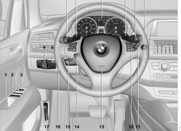
One lever for all functions
1 Storing and maintaining speed or accelerat‐
2 Storing and maintaining speed or deceler‐
ing
ating
3 Interrupting and deactivating the system 4 Resuming a speed stored beforehand
Online Edition for Part no. 01 40 2 606 735 - 03 11 500
Maintaining current speed Push, arrow 1, or pull, arrow 2, the lever to the resistance point. The car's current speed is stored and main‐ tained. It is displayed on the speedometer and briefly in the instrument cluster. On uphill gradients, it may prove impossible to maintain the set speed if current engine power output is insufficient. If the engine braking effect is insufficient on downhill slopes, the system will brake the vehicle slightly. Increasing desired speed Repeatedly press the lever to the resistance point or beyond, arrow 1, until the desired speed is reached. ▷ Each time the lever is pressed to the point of resistance, the desired speed increases by approx. 1 mph/1 km/h.
▷ Each time the lever is pressed beyond the resistance point, the desired speed is in‐ creased by up to 5 mph/10 km/h.
The system stores and maintains the speed. Accelerating using the lever Accelerating slightly: Press the lever to the resistance point, arrow 1, until the desired speed is reached. Accelerating significantly: Press the lever beyond the resistance point, ar‐ row 1, until the desired speed is reached. The vehicle accelerates without pressure on the accelerator pedal. The system stores and main‐ tains the speed. Decreasing speed Repeatedly pull the lever to the resistance point or beyond, arrow 2, until the desired speed is displayed. ▷ Each time the lever is pulled to the resist‐ ance point, the desired speed is decreased by approx. 1 mph/1 km/h.
▷ Each time the lever is pulled beyond the re‐ sistance point, the desired speed is reduced
by up to 5 mph/10 km/h until the minimum speed of 20 mph/30 km/h is achieved.
The system stores and maintains the speed. Interrupting the system Press the lever up or down, arrow 3: display 1 in the speedometer changes color, refer to page 109. In addition, the system is interrupted: ▷ When the brakes are applied. ▷ When the transmission position D is disen‐
gaged.
▷ When DTC is activated or DSC is deacti‐
vated.
▷ When DSC or ABS is intervening. Warning lamp
The warning lamp lights up if cruise control has been deactivated auto‐ matically, e.g., by a control interven‐ tion of the DSC. A message appears on the Con‐ trol Display.
Resuming cruising speed Press button 4: The stored speed is resumed and maintained. Deactivating the system ▷ Press the lever upward or downward twice,
arrow 3.
▷ Switch off the ignition. The stored speed is cleared. Displays in the instrument cluster
1 Stored desired speed
109
Online Edition for Part no. 01 40 2 606 735 - 03 11 500
t
▷ Green: the system is active. ▷ Orange: the system is interrupted. 2 Selected desired speed appears briefly If the display --- mph or --- km/h appears briefly, conditions may not be adequate to operate the system. Call up Check Control messages, refer to page 77. Malfunction
The warning lamp comes on when the system has failed. A message appears on the Control Display. More information, refer to page 76.
Park Distance Control PDC* The concept In addition to the PDC Park Distance Control, the backup camera*, refer to page 112, can be switched on. PDC supports you when parking. A slow ap‐ proach to an object in front of or behind your ve‐ hicle is announced by: ▷ Signal tones. ▷ Visual display. Measurement Measurements are made by ultrasound sensors in the bumpers. The range is approx. 6 ft/2 m. An acoustic warning is first given: ▷ By the front* sensors and two rear corner
sensors at approx. 24 in/60 cm.
▷ By the rear middle sensors at approx. 5 ft/
1.50 m.
System limits
Check the traffic situation as well PDC cannot serve as a substitute for the driver's personal judgment of the traffic situa‐ tion. Check the traffic situation around the vehi‐
110
cle with your own eyes. Otherwise, an accident could result from road users or objects located outside of the PDC detection range. Loud noises from outside and inside the vehicle may prevent you from hearing the PDC's signal tone.◀
Avoid driving quickly with PDC Avoid approaching an object quickly.
Avoid driving away quickly while PDC is not yet active. For technical reasons, the system may other‐ wise be too late in issuing a warning.◀
Limits of ultrasonic measurement The detection of objects can reach the physical limits of ultrasonic measurement, for instance: ▷ With tow bars and trailer hitches. ▷ With thin or wedge-shaped objects. ▷ With low objects. ▷ With objects with corners and sharp edges. Low objects already displayed, e.g., curbs, can move into the blind area of the sensors before or after a continuous tone sounds. High, protruding objects such as ledges may not be detected. False warnings PDC may issue a warning under the following conditions even though there is no obstacle within the detection range: ▷ In heavy rain. ▷ When sensors are very dirty or covered in
ice.
▷ When sensors are covered in snow. ▷ On rough road surfaces. ▷ In large buildings with right angles and
smooth walls, e.g., in underground garages.
▷ In heavy exhaust. ▷ Due to other ultrasound sources, e.g.,
sweeping machines, high pressure steam cleaners or neon lights.
Online Edition for Part no. 01 40 2 606 735 - 03 11 500
Switching on automatically With the engine running or the ignition switched on, shift the selector lever into position R. Switching off automatically The system switches off and the LED goes out: ▷ After approx. 165 ft/50 m when driving for‐
ward.
▷ After approx. 22 mph/35 km/h when driving
forward.
Switch on the system again if necessary. Switching on/off manually
▷ If the vehicle stops in front of an object that is detected by only one of the corner sen‐ sors.
▷ If moving parallel to a wall. The signal tone is switched off: ▷ When the vehicle moves away from an ob‐
ject by more than approx. 4 in/10 cm.
▷ When transmission position P is engaged. Volume You can set the volume of the PDC signal tone, refer to page 173. The setting is stored for the remote control cur‐ rently in use. Visual warning The approach to an object can be shown on the Control Display. Objects that are farther away are displayed on the Control Display before a signal tone sounds.
Press the button. ▷ On: the LED lights up. ▷ Off: the LED goes out. Signal tones When approaching an object, an intermittent tone is sounded that indicates the position of the object. For example, if an object is detected to the left rear of the vehicle, a signal tone sounds from the left rear speaker. The shorter the distance to the object becomes, the shorter the intervals. If the distance to a detected object is less than approx. 12 in/30 cm, a continuous tone is sounded. If objects are located both in front of and behind the vehicle, an alternating continuous signal is sounded. The intermittent tone is interrupted after approx. 3 seconds:
The display appears as soon as PDC is acti‐ vated. If the last image selected was the rear view cam‐ era, this is displayed again. To switch to PDC:
"Switch off rear view camera"
The setting is stored for the remote control cur‐ rently in use. Image on the Control Display Switching on the rear view camera using iDrive With PDC activated:
"Rear view camera"
Online Edition for Part no. 01 40 2 606 735 - 03 11 500
111
the region behind your vehicle is shown on the Control Display. System limits
Check the traffic situation as well Check the traffic situation around the ve‐ hicle with your own eyes. Otherwise, an accident could result from road users or objects located outside the picture area of the backup camera.◀
Detection of objects High, protruding objects such as ledges may not be detected by the backup camera.◀
Switching on automatically With the engine running or the ignition switched on, shift the selector lever into position R. The image of the rear view camera is displayed when the system has been switched on using iDrive. Switching off automatically The system switches off and the LED goes out: ▷ After approx. 33 ft/10 m when driving for‐
ward.
▷ After approx. 9 mph/15 km/h when driving
forward.
Switch on the system again if necessary. Switching on/off manually
The image of the rear view camera is displayed. The setting is stored for the remote control cur‐ rently in use. Malfunction
A Check Control message, refer to page 76, is displayed in the instrument cluster. The areas in front of and behind the vehicle ap‐ pear in shaded form on the Control Display. PDC has failed. Have the system checked. To ensure full operability: ▷ Keep the sensors clean and free of ice. ▷ When using high-pressure washers, do not spray the sensors for long periods and main‐ tain a distance of at least 12 in/30 cm.
Surround View* The concept Surround View encompasses the following sys‐ tems: ▷ Backup camera*, refer to page 112. ▷ Top View*, refer to page 114. ▷ Side View*, refer to page 116. It provides assistance when parking and ma‐ neuvering and at blind driveways and intersec‐ tions.
Backup camera* The concept The rear view camera assists you when parking and maneuvering in reverse. To accomplish this,
Press the button. ▷ On: the LED lights up. ▷ Off: the LED goes out. If PDC is displayed, switch on the backup cam‐ era via the iDrive, refer to page 111.
112
Online Edition for Part no. 01 40 2 606 735 - 03 11 500
Assistance functions Functional requirement ▷ Rear view camera is switched on. ▷ Tailgate is completely closed. Pathway lines
Show the parking aid lines via the iDrive, refer to page 114. Parking using pathway and turning lines 1. Position the vehicle so that the turning lines lead into the margins of the parking space.
▷ Can be displayed in the image of the rear
view camera when the transmission is in re‐ verse.
▷ Help estimate the required amount of space when parking and maneuvering on a flat road surface.
▷ Depend on the current steering angle and are continuously adapted to movements of the steering wheel.
Show the parking aid lines via the iDrive, refer to page 114. Turning lines
2. Turn the steering wheel to the point where the pathway line covers the corresponding turning circle line.
Obstacle marking
▷ Can be displayed in the image of the rear
view camera.
▷ Show the path of the smallest turning circle
on a flat road surface.
▷ When the steering wheel is turned, only one
turning line is displayed.
▷ Three-dimensionally shaped markings can be displayed in the image of the rear view camera.
Their color gradation corresponds to the mark‐ ings in PDC. This helps estimate the distance to the object pictured.
Online Edition for Part no. 01 40 2 606 735 - 03 11 500
113
t
Show the obstacle marking via the iDrive, refer to page 114. Activating assistance functions Several assistance functions can be active at the same time. Showing the parking aid lines "Parking aid lines"
Pathway and turning lines are displayed. Showing the obstacle marking "Obstacle marking"
Three-dimensionally-shaped markings are dis‐ played. Image on the Control Display Switching on the rear view camera using iDrive With PDC activated:
"Rear view camera"
The image of the rear view camera is displayed. The setting is stored for the remote control cur‐ rently in use. Brightness With the rear view camera switched on: 1. 2. Turn the controller until the desired setting
Select the symbol.
is reached and press the controller.
Contrast With the rear view camera switched on: 1. 2. Turn the controller until the desired setting
Select the symbol.
is reached and press the controller.
Camera
The lens of the rear view camera is under the grasping lip of the tailgate. The presence of dirt can impair image quality. Clean the lens with a moist, nonabrasive cloth.
Top View* The concept Top View assists you when parking and maneu‐ vering. To accomplish this, the door region and road surface region are shown on the Control Display. Detection Detection is carried out by two cameras integrated into the exterior mirror and the rear view camera. The range is: ▷ Approx. 7 ft/2 m to the side. ▷ Approx. 7 ft/2 m to the rear. Obstacles up to the height of the exterior mirrors are thus detected in a timely fashion. System limits Top View cannot be used in the following situa‐ tions: ▷ With a door open. ▷ With the tailgate open. ▷ With an exterior mirror folded in. ▷ In poor light. The arrows next to the vehicle are displayed in a shaded form on the Control Display and a sym‐
114
Online Edition for Part no. 01 40 2 606 735 - 03 11 500
bol appears at the corresponding location on the vehicle.
Check the traffic situation as well Check the traffic situation around the ve‐ hicle with your own eyes. Otherwise, an accident could result from road users or objects located outside the picture area of the cameras.◀
Switching on automatically Select transmission position R with the engine running. The images from Top View and PDC are dis‐ played when the system has been switched on using iDrive. Switching off automatically The system switches off and the LED goes out: ▷ After approx. 165 ft/50 m when driving for‐
ward.
▷ After approx. 22 mph/35 km/h when driving
forward.
Switch on the system again if necessary. Switching on/off manually
Press the button. ▷ On: the LED lights up. ▷ Off: the LED goes out. If Top View is displayed, switch on the backup camera via the iDrive, refer to page 114. Visual warning The approach to an object can be shown on the Control Display.
When the distance to an object is small, the PDC display correspondingly shows a red bar in front of the vehicle.
The display appears as soon as Top View is ac‐ tivated. If the last image selected was the rear view cam‐ era, this is displayed again. To switch to Top View:
"Rear view camera" Select the symbol on
the Control Display. The setting is stored for the remote control cur‐ rently in use. Image on the Control Display Switching on the rear view camera using iDrive With Top View activated: "Rear view camera"
The image of the rear view camera is displayed. The setting is stored for the remote control cur‐ rently in use. Brightness With Top View switched on: 1. 2. Turn the controller until the desired setting
"Brightness"
is reached and press the controller.
Contrast With Top View switched on: 1. 2. Turn the controller until the desired setting
"Contrast"
is reached and press the controller.
Online Edition for Part no. 01 40 2 606 735 - 03 11 500
115
t
Displaying turning lines and pathway lines ▷ The static, red turning line shows the lateral
space required when the wheel is fully turned.
▷ The variable, green pathway lines assist you in estimating the amount of lateral space ac‐ tually required. The pathway lines depend on the current steering angle and are continuously adapted to movements of the steering wheel.
"Parking aid lines"
Turning lines and pathway lines are displayed. Cameras
Display The images from both cameras are shown si‐ multaneously on the Control Display.
Check the traffic situation as well Check the traffic situation around the ve‐ hicle on blind driveways and intersections with your own eyes. Otherwise, an accident could re‐ sult from road users or objects located outside the picture area of the Side View cameras.◀
Switching off automatically System switches off: above approx. 9 mph/ 15 km/h. Switch on the system again if necessary. Switching on/off manually
The lenses of the Top View cameras are on the undersides of the exterior mirror housings. The presence of dirt can impair image quality. Clean the lens with a moist, nonabrasive cloth.
Side View* The concept Side View provides an early look at cross traffic at blind driveways and intersections. Road users concealed by obstacles to the left and right of the vehicle can only be detected from the driv‐ er's seat at the last minute. To improve visibility, two cameras in the front of the vehicle record the traffic situation on each side. System limits The cameras capture a maximum range of 330 ft/100 m.
116
Press the button.
Image on the Control Display The traffic area to the left and right is displayed on the Control Display.
Guidelines at the bottom of the image show the position of the front of the vehicle.
Brightness With the Side View switched on:
Online Edition for Part no. 01 40 2 606 735 - 03 11 500
"Brightness"
1. 2. Turn the controller until the desired setting
is reached and press the controller.
Contrast With the Side View switched on: 1. 2. Turn the controller until the desired setting
"Contrast"
is reached and press the controller.
Cameras
The two camera lenses are located on the sides of the bumper. The presence of dirt can impair image quality. Clean the lens, refer to page 287.
Head-up Display* The concept This system projects important information into the driver's field of vision, e.g., navigation in‐ structions. In this way, the driver can get information with‐ out averting his or her eyes from the road.
Switching on/off
Press the button.
Display visibility The visibility of the displays in the Head-up Dis‐ play is influenced by: ▷ Certain sitting positions. ▷ Objects on the cover of the Head-up Dis‐
play.
▷ Sunglasses with certain polarization filters. ▷ Wet roads. ▷ Unfavorable light conditions. If the image is distorted, check the basic set‐ tings.
Online Edition for Part no. 01 40 2 606 735 - 03 11 500
117
t
Display
1 Navigation instructions* 2 Active Cruise Control with Stop & Go func‐
tion*
3 Lane departure warning* 4 Cruise control/desired speed* 5 Current speed The Check Control messages are displayed briefly if needed. Selecting displays in the Head-up Display 1. "Settings" 2. "Head-up display" 3. "Displayed information" 4. Select the desired displays in the Head-up
Display.
1. "Settings" 2. "Head-up display" 3. "Brightness" 4. Turn the controller.
The brightness is adjusted.
With the low beams switched on, the brightness can also be adjusted with the thumbwheel of the instrument lighting. The setting is stored for the remote control cur‐ rently in use. Height adjustment 1. "Settings" 2. "Head-up display" 3. "Height" 4. Turn the controller.
The height is adjusted.
The setting is stored for the remote control cur‐ rently in use. Special windshield The windshield is part of the system. The shape of the windshield makes it possible to display a precise image. A film in the windshield prevents double images from being displayed. Therefore, have the special windshield replaced by a service center only.
The settings are stored for the remote control currently in use. Setting the brightness The brightness is automatically adjusted to the ambient light. The basic setting can be adjusted manually.
118
Online Edition for Part no. 01 40 2 606 735 - 03 11 500
Climate At a glance
1 Air toward the windshield and side windows 2 Air for the upper body 3 Air to footwell 4 Automatic climate control with 2-zone con‐
trol 120
Automatic climate control with 4-zone con‐ trol 124Online Edition for Part no. 01 40 2 606 735 - 03 11 500
119
Automatic climate control with 2-zone control
1 Seat heating and ventilation, driver's
side 49
partment
partment
2 Temperature, left side of passenger com‐
3 AUTO program 4 Temperature, right side of passenger com‐
5 Maximum cooling 6 Seat heating and ventilation, front passen‐
ger side 49
7 Passenger side
▷ Manual air distribution
The current setting for manual air distribution is displayed on the Control Display. Comfortable interior climate The AUTO program offers the optimum air dis‐ tribution and air volume for virtually all condi‐ tions, refer to AUTO program below. Select a comfortable interior temperature only. The following sections contain more detailed in‐ formation on the available setting options. Most of these settings are stored for the remote control currently in use, Personal Profile set‐ tings, refer to page 29.
▷ Accessing setting for ventilation tem‐
perature on the Control Display
8 Switching cooling function on/off manually 9 Automatic recirculated air control/recircu‐
lated air mode
10 Manual air volume, switching off automatic
climate control, residual heat
11 Rear window defroster 12 Defrosting windows and removing conden‐
sation
13 Air grill for interior temperature sensor,
please keep clear and unobstructed
14 Driver's side
▷ Manual air distribution ▷ Accessing setting for ventilation tem‐
perature on the Control Display
AUTO program
Press the button. Air volume, air distribution, and temperature are controlled auto‐ matically.
Depending on the selected temperature, AUTO intensity, and outside influences, the air is di‐ rected to the windshield, side windows, upper body, and into the footwell. The cooling function is switched on automati‐ cally with the AUTO program. At the same time, a condensation sensor con‐ trols the program in such a way that window condensation is prevented as much as possible.
120
Online Edition for Part no. 01 40 2 606 735 - 03 11 500
To switch off the program: press the button again or manually adjust the air distribution. Intensity of the AUTO program Pressing the AUTO button repeatedly adjusts the intensity of the AUTO program. The se‐ lected intensity, SOFT, MEDIUM or INTENSIVE, appears on the display of the automatic climate control. Temperature
Turn the wheel to set the desired temperature. The automatic climate control ach‐ ieves this temperature as quickly as possible, if necessary with the max‐
imum cooling or heating capacity, and then keeps it constant. Avoid rapidly switching between different tem‐ perature settings. The automatic climate control will not have sufficient time to adjust the set temperature. Maximum heating power can be obtained with the highest setting, regardless of the external temperature. At the lowest setting, cooling is continuous, re‐ gardless of the external temperature. Adjusting the ventilation temperature This function can be used to adjust the air tem‐ perature for the upper body region. 1. "Settings" 2. "Climate" 3. "Driver ventilation" or "Front passenger
ventilation"
4. Turn the controller to adjust the tempera‐
ture. ▷ Blue: colder ▷ Red: warmer
Defrosting and defogging windows
Press the button. Ice and condensation are quickly re‐ moved from the windshield and the front side windows. For this purpose, also switch on the cooling function. Rear window defroster Press the button. The rear window defroster switches off
automatically after a certain period of time. Depending on the vehicle equipment, upper wires are used as an antenna and are not part of the rear window defroster.
Air volume, manual
You can vary the air volume by pressing on the corresponding side. You can re‐ activate the automatic mode for the air flow rate with the AUTO button.
Manual air distribution The air flow can be guided into the vehicle inte‐ rior, separately for the driver's and front passen‐ ger side, using one of the following programs: ▷ Upper body region. ▷ Upper body region and footwell. ▷ Footwell. ▷ Driver's side: in addition, the windshield,
side windows, and footwell.
Online Edition for Part no. 01 40 2 606 735 - 03 11 500
121
Selecting program
Press the button repeatedly until the desired program is shown on the Con‐ trol Display.
1 Air toward the windshield and side windows 2 Air for the upper body 3 Air to footwell Pressing the AUTO button cancels the manual air distribution settings. The automatic mode for the air volume remains effective with manual air distribution. Cooling function The passenger compartment can only be cooled with the engine running.
Press the button. The air is cooled and dehumidified and
– depending on the temperature setting – warmed again. The cooling function helps to prevent conden‐ sation on the windows or to remove it quickly. Depending on the weather, the windshield may fog up briefly when the engine is started. The cooling function is switched on automati‐ cally with the AUTO program. When using the automatic climate control, con‐ densation water, refer to page 144, develops that exits underneath the vehicle. Maximum cooling
Press the button. The system is set to the lowest temperature, maximum air volume and recirculated-air mode.
Air flows out of the vents for the upper body re‐ gion. Open them for this purpose. Air is cooled as quickly as possible: ▷ At an external temperature of approx. 32 ℉/
0 ℃.
▷ When the engine is running. Automatic recirculated air mode/ recirculated air mode You can respond to unpleasant odors or pollu‐ tants in the immediate environment by tempo‐ rarily suspending the supply of outside air. The system then recirculates the air currently within the vehicle.
Press the button repeatedly to select an operating mode:
▷ LEDs off: outside air flows in continuously. ▷ Left LED on, automatic recirculated-air con‐ trol: a sensor detects pollutants in the out‐ side air and controls the shutoff automati‐ cally.
▷ Right LED on, recirculated air mode: the
supply of outside air into the vehicle is per‐ manently blocked.
If the windows are fogged over, switch off the recirculated-air mode and press the AUTO but‐ ton to utilize the condensation sensor. Make sure that air can flow onto the windshield.
Continuous recirculated-air mode The recirculated air mode should not be used for an extended period of time, as the air quality inside the vehicle deteriorates steadily.◀
Residual heat The heat stored in the engine is used to heat the interior. Functional requirement ▷ Up to 15 minutes after the engine has been
switched off. ▷ Warm engine. ▷ The battery is sufficiently charged. ▷ External temperature below 77 ℉/25 ℃.
122
Online Edition for Part no. 01 40 2 606 735 - 03 11 500
Switching on 1. Switch off the ignition. 2. Press the right-hand button.
REST appears on the display of the automatic climate control when the residual heat utilization is switched on. From radio readiness the interior temperature, the air volume and the air distribution can be set. Switching off You can select the lowest blower speed by pressing and holding the left side. Pressing again switches off the residual heat utilization. REST disappears from the display of the auto‐ matic climate control. Switching on/off the automatic climate control Switching off
With the blower at its lowest setting, press the left side of the button to
switch off the automatic climate control.
Switching on Press any button to switch the automatic cli‐ mate control back on. Front ventilation
Avoiding injury Do not drop any foreign objects into the air vents, otherwise these could be catapulted out‐ wards and lead to injuries.◀
Ventilation for cooling Adjust the vents to direct the flow of cool air in your direction, for instance if the interior has be‐ come too warm. Draft-free ventilation Set the air vents so that the air flows past you and is not directed straight at you. Ventilation in rear
1 Use the thumbwheels to smoothly open and
close the air vents
2 Use the lever to change the direction of the
air flow
BMW X5: heating and ventilation, 3rd row seats The air in the area of the 3rd row seats can be heated or recirculated. Air vents are located in the storage compartment area between the seats and in the footwell of the 3rd row seats.
1 Use the thumbwheels to smoothly open and
close the air vents
2 Use the lever to change the direction of the
air flow
1 Thumbwheel
123
Online Edition for Part no. 01 40 2 606 735 - 03 11 500
e
▷ Activating heating and distributing air in
footwell: