- 2010 Volvo S40 Owners Manuals
- Volvo S40 Owners Manuals
- 2006 Volvo S40 Owners Manuals
- Volvo S40 Owners Manuals
- 2007 Volvo S40 Owners Manuals
- Volvo S40 Owners Manuals
- 2011 Volvo S40 Owners Manuals
- Volvo S40 Owners Manuals
- 2005 Volvo S40 Owners Manuals
- Volvo S40 Owners Manuals
- 2008 Volvo S40 Owners Manuals
- Volvo S40 Owners Manuals
- Download PDF Manual
-
Remote control functions 1. Lock - Press the Lock button on the remote once to lock all doors and the trunk. The turn signals will flash once to confirm locking. 2. Unlock - Press the Unlock button on the remote once to unlock the driver's door. The turn signals will flash twice to confirm unlocking. After a short pause, press the Unlock button a second time within 10 seconds to unlock the other doors and the trunk. A long press (at least two seconds) opens all side windows.
NOTE:
The turn signals flash to confirm that the vehicle has been correctly locked/ unlocked with the remote control. When
locking the vehicle, the turn signals will flash a confirmation only if all the doors are securely closed and locked. Flashing confirmation for locking and unlocking may be customized in the vehicle's Personal settings menu. See page 56 for more information.
The two-step unlocking function can be changed so that one press of the Unlock button unlocks all of the doors and
the trunk. See Personal settings on page 56 for more information.
Automatic relocking: If the doors are unlocked, the locks will automatically reengage (re-lock) and the alarm will
rearm after 2 minutes unless a door or the trunk has been opened.
Automatic locking: When the car starts to move, the doors and trunk can be locked automatically. This feature can
be turned on or off, see Personal settings on page 56 for more information.
Airbag deployment will automatically attempt to unlock the doors.
3. Approach lighting - As you approach the car: Press the yellow button on the remote control to light the interior lighting, position/parking lamps, license plate lighting and the lights in the door mirrors (option). These lights will switch off automatically after 30, 60 or 90
seconds. See the Personal settings on page 56 for information about adjusting the time setting. 4. Unlock trunk- Press the button once to disarm the alarm system and unlock only the trunk. After closing, the trunk will not automatically relock. Press Lock to relock it and rearm the alarm. 5. Panic alarm: - This button can be used to attract attention during emergency situations. To activate the panic alarm, press and hold the red button for at least 3 seconds or press it twice within 3 seconds. The turn signals and horn will be activated. The panic alarm will stop automatically after 30 seconds. To deactivate, wait approximately 5 seconds and press the red button again.NOTE: This button will NOT unlock the car.
pg. 84 Remote control and key blade
Removing the key blade
Key blade The key blade can be removed from the remote control. When removed, the key blade can be used as follows:
To lock/unlock the driver's door To lock/unlock the glove compartment (see page 87) For valet locking (see the explanation in below)
Removing the key blade Slide the spring loaded catch (1 in the illustration shown) to the side and pull the key blade (2) out of the remote control.
Reinserting the key blade in the remote control
Hold the remote control with the pointed end down. Carefully slide the key blade into its groove. Gently press the key blade in the groove until it clicks into place.
Unlocking the doors with the detached key blade
Insert the key blade as far as possible in the driver's door lock. Turn the key blade clockwise approximately one-
quarter turn to unlock the driver's door only.
NOTE: After unlocking the driver's door with the key blade, opening the door will trigger the alarm. To disable the alarm:
Press the Unlock button on the remote control, or insert the key in the ignition switch.
Locking the doors with the detached key blade
Lock the rear doors and the front passenger's door by pressing the lock button on each door. Turn the key blade one-quarter turn counter-clockwise to lock the driver's door.
NOTE: This does not arm the alarm or lock the trunk.
pg. 85 Valet locking
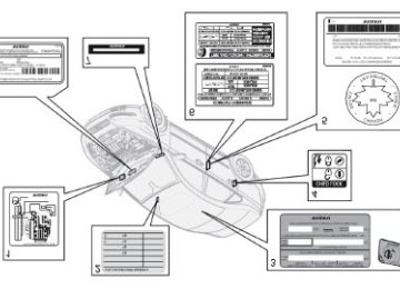
1. Normal locking/unlocking points 2. Locking/unlocking points with valet locking activated
Valet or service locking By utilizing the remote control with the key blade removed, the valet locking feature enables you to block access to the trunk and glove compartment for e.g. valet parking or when the car is brought to the retailer for service.
With the valet locking function activated:
The vehicle's doors can be locked or unlocked The engine can be started The glove compartment cannot be unlocked Access to the trunk is blocked (the trunk lid cannot be unlocked or opened, and the rear seat backrests are locked in
the upright position)
Activating the valet locking function 1. Remove the key blade from the remote control. 2. Turn the key blade 180° clockwise in the glove compartment lock to lock the glove compartment and disconnect the trunk lock from the central locking system. (A message appears in the information display.) 3. Lock the rear seat backrests in the upright position by inserting the key blade into the locks located on the upper outboard edge of the backrests. Passenger's side: Turn the key counterclockwise to lock the backrest. Driver's side: Turn the key clockwise to lock the backrest.
4. Give the parking attendant or service personnel only the remote control (with the key blade removed).
Deactivating the valet locking function
Turn the key blade 180° counterclockwise in the glove compartment lock to deactivate valet locking, and use the key blade to unlock the rear seat backrests.
pg. 86 Remote control battery
Weak battery in the remote control When the battery begins to lose its charge, the Information symbol in the instrument panel (see page 35) lights up and REMOTE BATTERY LOW VOLTAGE is shown in the information display.
Replacing the battery in the remote control If the range of the transmitter is noticeably reduced, this indicates that the battery (type CR 2032, 3V) is weak and should be replaced. To replace the battery: 1. Remove the key blade. 2. Place the remote control with the keypad downward. Remove the screw (1) using a small slotted screwdriver. 3. Remove the cover. 4. Note how the + and - sides of the battery are positioned on the inside of the cover. The plus side of the new battery (marked on the battery) must face downward.
CAUTION! When replacing the battery, avoid touching the electrical circuitry in the other half of the remote control.
5. Pry out (2) and replace the battery. Avoid touching the battery and its contact surfaces with your fingers. 6. Press the cover back into place and tighten the screw. 7. Reinsert the key blade in the remote control.
NOTE: The old battery should be disposed of properly at a recycling center or by a trained and qualified Volvo service technician.
pg. 87 Locking and unlocking
Locking/unlocking the car from the inside The switches near the door opening handles on the driver's and front passenger's doors can be used to lock or unlock all doors and the trunk, and to set the alarm.
Press in the upper section in the lock button. A long press (at least two seconds) also opens all the side windows.
Unlocking:
Locking:
NOTE:
Press in the lower section of the lock button.
The doors cannot be opened by pulling up the lock button. Each door can also be locked manually using the lock button on that particular door. This applies only if the car has
not been locked from the outside.
The doors can also be unlocked (and the door opened) by pulling the handle in the door twice.
Opening the trunk from the inside
Opening the trunk from the inside U.S. models only The car is equipped with a florescent handle on the inside of the trunk lid, which can be used in an emergency situation to open the trunk from the inside. Pull the handle down to release the trunk lid. After use, the handle must be pushed back into its original position before the trunk can be closed.
pg. 88 Locking the glove compartment, Child safety locks
Locking the glove compartment The glove compartment can only be locked and unlocked using the detachable key blade on the remote control. See page 84 for information on removing the key blade from the remote control.
Unlock the glove compartment by turning the key a quarter of a turn (90°) counterclockwise. The key slot is vertical
Lock the glove compartment by turning the key a quarter of a turn (90°) clockwise. The key slot is horizontal when
when the glove compartment is unlocked.
the glove compartment is locked.
Manual child safety locks, rear doors The controls are located on the rear inside edges of the doors, and are only accessible when the doors are open. Use the ignition key blade or a screwdriver to turn the control. A. The door cannot be opened from the inside when the slot in the control is in the horizontal position. The door can be opened from the outside. B. The door can be opened from the inside when the slot in the control is in the vertical position.
pg. 89 Alarm
The alarm system The alarm is automatically armed whenever the car is locked with the remote control, or if a front lock button is depressed. When armed, the alarm continuously monitors a number of points on the car. The following conditions will trigger the alarm:
The hood is forced open. The trunk is forced open. A door is forced open. The ignition switch is tampered with An attempt is made to start the car with a non-approved key (a key not coded to the car's ignition). If there is movement in the passenger compartment (if the car is equipped with the optional movement sensor).
The car is lifted or towed (if the car is equipped with the optional inclination sensor) The battery is disconnected (while the alarm is armed). The siren is disconnected when the alarm is disarmed.
Alarm indicator light
The alarm indicator light The status of the alarm system is indicated by the indicator light on at the top of the dashboard (see illustration):
Indicator light off - the alarm is not armed The indicator light flashes every two seconds - the alarm is armed The indicator light flashes rapidly before the ignition is switched on - the alarm has been triggered. The message
"ALARM TRIGGERED, CHECK CAR" will also be displayed.
Fault in the alarm system: If a fault has been detected in the alarm system, a message will be shown in the
information display. Contact a trained and qualified Volvo service technician to have the alarm system inspected and repaired if necessary.
Arming the alarm Press the LOCK button on the remote control, or press the central lock button on one of the front doors with the door open. One long flash of the turn signals will confirm that the alarm is armed.
Disarming the alarm Press the UNLOCK button on the remote control or insert the key in the ignition to disarm the alarm. Two short flashes from the car's direction indicators confirm that the alarm has been deactivated and that all doors are unlocked.
Turning off (stopping) the alarm If the alarm is sounding, it can be stopped by pressing the UNLOCK button on the remote control or by inserting the key in the ignition switch.
Audible/visual alarm signal An audible alarm signal is given by a battery powered siren. The alarm cycle lasts for 30 seconds.
pg. 90 Alarm
1. Disconnecting the sensors. 2. Not in use
The visual alarm signal is given by flashing all turn signals and turning on the interior lighting for approximately 5
minutes.Temporarily turning off the accessory alarm sensor(s) In certain situations it may be desirable to turn off the accessory inclination and movement alarm sensors if, for example, you drive your vehicle onto a ferry where the rocking of the boat could trigger the alarm or if a pet is left in the vehicle with the doors locked. 1. Turn the ignition key to position II and then back to position 0 and remove it from the ignition switch. 2. Press the button (1). The LED in the button will remain on for one minute after the key has been removed from the ignition switch or until the car is locked.
Important
The accessory sensors are automatically reconnected to the alarm system the next time the vehicle is unlocked and
then locked again.
This function will not turn off the vehicle's standard alarm.
U,S.A. FCC ID: MAYDA 5823(3)
This device complies with part 15 of the FCC rules. Operation is subject to the following conditions: (1) This device may not cause harmful interference, and (2) this device must accept any interference received, including interference that may cause undesired operation.
Canada IC: 4405A-DA 5823(3)
Movement sensor DA5823 by Dynex Operation is subject to the following conditions: (1) this device may not cause interference, and (2) this device must accept any interference, including interference that may cause undesired operation of the device.
Contents | Top of Page
2 0 0 6
VOLVOS40
Chapter 7 - Starting and driving
pg. 91 Starting and driving
General information 92
Fuel requirements 95
Ignition switch and steering wheel lock 98
Starting the vehicle 99
Manual transmission, 5-speed 101
Manual transmission, 6-speed 102
Automatic transmission - Geartronic 103
Shiftlock override 105
All Wheel Drive (option) 106
Brake system 107
Stability system 109
Rear park assist (accessory) 111
Towing 112
Jump starting 114
Towing a trailer 115
Detachable trailer hitch 117
Transporting loads 118pg. 92 General information
Economical driving conserves natural resources Better driving economy may be obtained by thinking ahead, avoiding rapid starts and stops and adjusting the speed of your vehicle to immediate traffic conditions. Observe the following rules:
Bring the engine to normal operating temperature as soon as possible by driving with a light foot on the accelerator
pedal for the first few minutes of operation. A cold engine uses more fuel and is subject to increased wear.
Whenever possible, avoid using the vehicle for driving short distances. This does not allow the engine to reach
normal operating temperature.
Drive carefully and avoid rapid acceleration and hard braking. Use the transmission's (D)rive position as often as possible and avoid using kickdown. Do not exceed posted speed limits. Avoid carrying unnecessary items (extra load) in the vehicle. Maintain correct tire pressure. Check tire pressure regularly (when tires are cold). Remove snow tires when threat of snow or ice has ended. Note that roof racks, ski racks, etc, increase air resistance and also fuel consumption. At highway driving speeds, fuel consumption will be lower with the air conditioning on and the windows closed
than with the air conditioning off and the windows open.
Using the onboard trip computer's fuel consumption modes can help you learn how to drive more economically.
Other factors that decrease gas mileage are:
Dirty air cleaner Dirty engine oil and clogged oil filter Dragging brakes Incorrect front end alignment
Some of the above mentioned items and others are checked at the standard maintenance intervals.
Weight distribution affects handling At the specified curb weight your vehicle has a tendency to understeer, which means that the steering wheel has to be turned more than might seem appropriate for the curvature of a bend. This ensures good stability and reduces the risk of rear wheel skid. Remember that these properties can alter with the vehicle load. The heavier the load in the cargo area, the less the tendency to understeer.
WARNING! Driving with the trunk open: Driving with the trunk open could lead to poisonous exhaust gases entering the passenger compartment. If the trunk must be kept open for any reason, proceed as follows: Close the windows Set the ventilation system control to air flow to floor, windshield and side windows and the blower control to its highest setting.
CAUTION! Drive slowly and carefully if going through standing water (i.e. flooded roadways, etc.). Damage to the engine could result if excess water is drawn in through the air intake system. Never drive the vehicle in water deeper than 18
inches (48 cm).pg. 93 General information
Handling, roadholding Vehicle load, tire design and inflation pressure all affect vehicle handling. Therefore, check that the tires are inflated to the recommended pressure according to the vehicle load. See the "Tire pressure" section. Loads should be distributed so that capacity weight or maximum permissible axle loads are not exceeded.
Cold weather precautions If you wish to check your vehicle before the approach of cold weather, the following advice is worth noting:
Make sure that the engine coolant contains 50 percent antifreeze. Any other mixture will reduce freeze protection. This gives protection against freezing down to -31°F (-35°C). See section "Coolant". The use of "recycled" antifreeze
is not approved by Volvo. Different types of antifreeze must not be mixed.
Volvo recommends using only genuine Volvo antifreeze in your vehicle's radiator. Try to keep the fuel tank well filled - this prevents the formation of condensation in the tank. In addition, in
extremely cold weather conditions it is worthwhile to add fuel line de-icer before refueling.
The viscosity of the engine oil is important. Oil with low viscosity (thinner oil) improves cold-weather starting as
well as decreasing fuel consumption while the engine is warming up. For winter use, 5W-30 oil, particularly the synthetic type1 , is recommended. Be sure to use good quality oil but do not use cold-weather oil for hard driving or in warm weather. See page 179 for more information.
The load placed on the battery is greater during the winter since the windshield wipers, lighting, etc. are used more
often. Moreover, the capacity of the battery decreases as the temperature drops. In very cold weather, a poorly charged battery can freeze and be damaged. It is therefore advisable to check the state of charge more frequently and spray an anti-rust oil on the battery posts.
Volvo recommends the use of snow tires on all four wheels for winter driving - see the chapter "Wheels and tires." To prevent the washer fluid reservoir from freezing, add washer solvents containing antifreeze (see page 145 for the
location of the washer fluid reservoir). This is important since dirt is often splashed on the windshield during winter driving, requiring the frequent use of the washers and wipers. Volvo Washer Solvent should be diluted as follows: Down to 14° F (-10° C): 1 part washer solvent and 4 parts water, Down to 5° F (-15° C): 1 part washer solvent and 3
parts water, Down to 0° F (-18° C): 1 part washer solvent and 2 parts water, Down to -18° F (-28° C): 1 part washer solvent and 1 part water.Use Volvo Teflon Lock Spray in the locks.
NOTE: Avoid using de-icing sprays as they can cause damage to the locks.
1. Synthetic oil is not used when the oil is changed at the normal maintenance intervals except at owner request and at additional charge.
Conserving electrical current Keep the following in mind to help minimize battery drain:
When the engine is not running, avoid turning the ignition key to position II. Many electrical systems (the audio
pg. 94 General information
system, the optional navigation system, power windows, etc) will function with the ignition key in position I. This position reduces drain on the battery.
Please keep in mind that using systems, accessories, etc that consume a great deal of current when the engine is not
running could result in the battery being completely drained.
The optional 12 volt socket in the trunk provides electrical current even with the ignition switched off, which drains
the battery.
NOTE: If the ignition is switched on, a warning message will be displayed in the text window in the instrument panel when the battery charge is low. An energy conserving function designed into the vehicle's electrical system will switch off certain functions or reduce the load on the battery by, e.g., reducing the audio system's volume.
Before a long distance trip It is always worthwhile to have your vehicle checked by a trained and qualified Volvo service technician before driving long distances. Your retailer will also be able to supply you with bulbs, fuses, spark plugs and wiper blades for your use in the event that problems occur. As a minimum, the following items should be checked before any long trip:
Check that engine runs smoothly and that fuel consumption is normal. Check for fuel, oil, and fluid leakage
Have the transmission oil level checked2. Check condition of drive belts. Check state of the battery's charge. Examine tires carefully (the spare tire as well), and replace those that are worn. Check tire pressures. The brakes, front wheel alignment, and steering gear should be checked by a trained and qualified Volvo service
technician only.
Check all lights, including high beams. Reflective warning triangles are legally required in some states/provinces. Have a word with a trained and qualified Volvo service technician if you intend to drive in countries where it may
Consider your destination. If you will be driving through an area where snow or ice are likely to occur, consider
be difficult to obtain the correct fuel.
snow tires.
2. To prevent injury from contact with hot surfaces, do not inspect your vehicle's transmission fluid yourself. Have your vehicle's transmission fluid level inspected by a trained and qualified Volvo service technician.
pg. 95 Fuel requirements
Octane rating Volvo engines are designed for optimum performance on unleaded premium gasoline with an AKI octane rating of 91
or above. AKI (ANTI KNOCK INDEX) is an average of the Research Octane Number, RON, and the Motor Octane Number, MON. ((RON + MON)/2). The minimum octane requirement is AKI 87 (RON 91).Deposit control gasoline (detergent additives) Volvo recommends the use of detergent gasoline to control engine deposits. Detergent gasoline is effective in keeping injectors and intake valves clean. Consistent use of deposit control gasolines will help ensure good driveability and fuel economy. If you are not sure whether the gasoline contains deposit control additives, check with the service station operator.
NOTE: Volvo does not recommend the use of store-bought fuel injector cleaning additives.
Unleaded fuel Each Volvo has a three-way catalytic converter and must use only unleaded gasoline. U.S. and Canadian regulations require that pumps delivering unleaded gasoline be labelled "UNLEADED". Only these pumps have nozzles which fit your vehicle's filler inlet. It is unlawful to dispense leaded fuel into a vehicle labelled "unleaded gasoline only". Leaded gasoline damages the three-way catalytic converter and the heated oxygen sensor system. Repeated use of leaded gasoline will lessen the effectiveness of the emission control system and could result in loss of emission warranty coverage. State and local vehicle inspection programs will make detection of misfueling easier, possibly resulting in emission test failure for misfueled vehicles.
NOTE: Some U.S. and Canadian gasolines contain an octane enhancing additive called methyl-cyclopentadienyl manganese tricarbonyl (MMT). If such fuels are used, your Emission Control System performance may be affected, and the Check Engine Light (malfunction indicator lamp) located on your instrument panel may light. If this occurs, please return your vehicle to a trained and qualified Volvo service technician for maintenance.
Gasoline containing alcohol and ethers Some fuel suppliers sell gasoline containing "oxygenates" which are usually alcohols or ethers. In some areas, state or local laws require that the service pump be marked indicating use of alcohols or ethers. However, there are areas in which the pumps are unmarked. If you are not sure whether there is alcohol or ethers in the gasoline you buy, check with the service station operator. To meet seasonal air quality standards, some areas require the use of "oxygenated" fuel. Volvo allows the use of the following "oxygenated" fuels; however, the octane ratings listed on this page must still be met. Alcohol - Ethanol: Fuels containing up to 10% ethanol by volume may be used. Ethanol may also be referred to as Ethyl alcohol, or "Gasohol". Ethers - MTBE: Fuels containing up to 15% MTBE may be used.
Fuel Formulations Do not use gasoline that contains lead as a knock inhibitor, and do not use lead additives. Besides damaging the exhaust emission control systems on your vehicle, lead has been strongly linked to certain forms of cancer. Many fuels contain benzene as a solvent. Unburned benzene has been strongly linked to certain forms of cancer. If you live in an area where you must fill your own gas tank, take precautions.
These may include:
standing upwind away from the filler nozzle while refueling
pg. 96 Fuel requirements (contd.)
refueling only at gas stations with vapor recovery systems that fully seal the mouth of the filler neck during
refueling
wearing neoprene gloves while handling a fuel filler nozzle.
WARNING! Carbon monoxide is a poisonous, colorless, and odorless gas. It is present in all exhaust gases. If you ever smell exhaust fumes inside the vehicle, make sure the passenger compartment is ventilated, and immediately return the vehicle to your retailer for correction.
Use of Additives With the exception of fuel line antifreeze during winter months, do not add solvents, thickeners, or other store-bought additives to your vehicle's fuel, cooling, or lubricating systems. Overuse may damage your engine, and some of these additives contain organically volatile chemicals. Do not needlessly expose yourself to these chemicals.
Fuel filler door Press the button on the light switch panel (see the illustration on page 41) with the ignition switched off to unlock the fuel filler door. Please note that the fuel filler door will remain unlocked until the vehicle begins to move forward. An audible click will be heard when the fuel filler door relocks. If you intend to leave your vehicle while it is being refueled, this feature enables you to lock the doors/trunk while leaving the fuel filler door unlocked. You can also keep the vehicle locked if you remain inside it during refueling. The central locking button does not lock the fuel filler door. Be sure the fuel filler door is not obstructed and is completely closed after refueling. Open the fuel filler cap slowly during hot weather.
Refueling The fuel tank is designed to hold approximately 15.9 US gallons (60 liters)1 with sufficient volume left over to accommodate possible expansion of the fuel in hot weather. Be aware that the "usable" tank capacity will be somewhat less than the specified maximum. When the fuel level is low, such factors as ambient temperature, the fuel's "Reid vapor pressure" characteristics, and terrain can affect the fuel pump's ability to supply the engine with an adequate supply of fuel. Therefore, it is advisable to refuel as soon as possible when the needle nears the red zone, or when the fuel warning light comes on.
1. Models with All Wheel Drive have a tank volume of 15 US gallons (57 liters). Models with engine code 39 have a fuel tank capacity of 14 US gallons (53 liters). This code is the 6th and 7th digits from the left in your vehicle's VIN number. See page 176 for the location of the VIN plate.
pg. 97 Fuel requirements
CAUTION! Do not refuel with the engine runninga. Turn the ignition off or to position I. If the ignition is on, an incorrect reading could occur in the fuel gauge After refueling, close the fuel filler cap by turning it clockwise until it clicks into place. Allow for fuel expansion by not overfilling the tank. Overfilling could also cause damage to the emission control systems. Avoid spilling gasoline during refueling. In addition to causing damage to the environment, gasolines containing alcohol can cause damage to painted surfaces, which may not be covered under the New Vehicle Limited Warranty. Do not use gasolines containing methanol (methyl alcohol, wood alcohol). This practice can result in vehicle performance deterioration and can damage critical parts in the fuel system. Such damage may not be covered under the New Vehicle Limited Warranty.
a. If the fuel filler cap is not closed tightly or if the engine is running when the vehicle is refueled, the Check Engine Light (malfunction indicator lamp) may indicate a fault. However, your vehicle's performance will not be affected. Use only Volvo original or approved fuel filler caps.
pg. 98 Ignition switch and steering wheel lock
0 - Locked position
Remove the key to lock the steering wheel1. Never turn the key to position 0 while driving or when the vehicle is being towed.
NOTE: A ticking sound may be audible if the key is turned to a position between 0 and I. To stop this sound, turn the key to position II and back to position 0.
I - Intermediate position2
Certain accessories, radio, etc. on, daytime running lights off
1. The gear selector must be in the Park position. 2. Please be aware that leaving the key in this position will increase battery drain.
II - Drive position
The key's position when driving. The vehicle's entire electrical system is activated.
III - Start position
Release the key when the engine starts. The key returns automatically to the Drive position. A chime will sound if the key is left in the ignition and the driver's door is opened.
Steering wheel lock When the key is removed from the ignition, the steering wheel locks so that it cannot be turned. If the front wheels are hard up against a curb, the steering wheel lock may be under too much tension to unlock. If so, the key will turn in the ignition switch but the car will not start. At the same time, a message "Steering locked" will appear in the driver information text display. If this happens: 1. Remove the key from the ignition. 2. Turn the steering wheel slightly and hold it to relieve pressure on the lock mechanism. Reinsert it the key. The steering should immediately unlock. If not, try again.
NOTE: In order to help reduce vehicle theft, make sure the steering wheel lock is engaged before leaving the vehicle.
WARNING! Never switch off the ignition (turn the ignition key to position 0) or remove the key from the ignition switch while the vehicle is in motion. This could cause the steering wheel to lock, which would make the vehicle impossible to steer.
pg. 99 Starting the vehicle
Starting the vehicle To start the engine: 1. Fasten the seat belt.
WARNING! Before starting, check that the seat, steering wheel and mirrors are adjusted properly. Make sure the brake pedal can be depressed completely. Adjust the seat if necessary.
2. Apply the parking brake if not already set. The gear selector (automatic transmission) is locked in the (P)ark position (SHIFTLOCK). See also page 103. Manual transmission: the clutch must be fully depressed.
3. Without touching the accelerator pedal, turn the ignition key to the starting position. Allow the starter to operate for up to 10 seconds. Release the key as soon as the engine starts. If the engine fails to start, repeat this step.
Autostart (T5 turbo with automatic transmission only) This function makes it possible to start the vehicle without holding the key in position III. Turn the key to position III and release it. The starter motor will then operate automatically (for up to ten seconds) until the engine starts.
NOTE: On certain models, when the vehicle is started, idle speed may be noticeably higher than normal for a short period, depending on the temperature of the engine. This has been done to help bring components in the emission control system to their normal operating temperature as quickly as possible, which enables them to function normally.
For cold starts at altitudes above 6000 ft. (1800 meters), depress the accelerator pedal halfway and turn the key to
the starting position. Release the pedal slowly when the engine starts.
4. To release the gear selector from the (P)ark position, the engine must be running (or the ignition key must be in position II) and the brake pedal must be depressed.
5. Select the desired gear. On models with an automatic transmission, the gear engages after a very slight delay which is especially noticeable when selecting R.
NOTE:
Immobilizer: If two of the keys to your vehicle are close together, e.g., on the same key ring when you try to start
the vehicle, this could cause interference in the immobilizer system and result in the vehicle not starting. If this should occur, remove one of the keys from the key ring before trying to start the vehicle again.
Keylock: Your vehicle is equipped with a keylock system. When the engine is switched off, the gear selector must
be in the (P)ark position before the key can be removed from the ignition switch.
When starting in cold weather, the automatic transmission may shift up at slightly higher engine speeds than normal
until the automatic transmission fluid reaches normal operating temperature.
Do not race a cold engine immediately after starting. Oil flow may not reach some lubrication points fast enough to
prevent engine damage.
WARNING! Volvo's floor mats are specially manufactured for your car. They must be firmly secured in the clips on the floor so that they cannot slide and become trapped under the pedals on the driver's side.
pg. 100 Starting the vehicle
CAUTION! Automatic transmission: The engine should be idling when you move the gear selector. Never accelerate until after you feel the transmission engage! Accelerating immediately after selecting a gear will cause harsh engagement and premature transmission wear. Selecting P or N when idling at a standstill for prolonged periods of time will help prevent overheating of the automatic transmission fluid.
WARNING! Always place the gear selector in Park and apply the parking brake before leaving the vehicle. Never leave the vehicle unattended with the engine running. Always open garage doors fully before starting the engine inside a garage to ensure adequate ventilation. The exhaust gases contain carbon monoxide, which is invisible and odorless but very poisonous.
pg. 101 Manual transmission, 5-speed
5-speed manual transmission (option on certain models) Depress the clutch pedal completely when changing gears1. Remove your foot from the clutch pedal while driving. The shift pattern should be followed. Overdrive (5th gear) should be used as often as possible to help improve fuel economy.
1. Clutch interlock The clutch must be fully depressed before you can start your car. If the clutch is not depressed, it will not be possible to start the engine.
Engaging reverse gear, 5-speed transmission Reverse gear should only be engaged from a complete stop.
CAUTION! Never shift into reverse while moving forward.
WARNING! An extra mat on the driver's floor can cause the accelerator, brake, and/or clutch pedal to catch. Check that the movement of these pedals is not impeded. Not more than one protective floor covering may be used at one time.
pg. 102 Manual transmission, 6-speed
6-speed manual transmission (option on certain models) Depress the clutch pedal completely when changing gears1. Remove your foot from the clutch pedal while driving. The shift pattern should be followed. Overdrive (5th and 6th gears) should be used as often as possible to help improve fuel economy.
Engaging reverse gear, 6-speed transmission Reverse gear should only be engaged from a complete stop.
NOTE: Reverse gear is electronically blocked and cannot be selected if the vehicle is moving at a speed of approximately 13 mph (20 km/h).
CAUTION! Never shift into reverse while moving forward.
WARNING! An extra mat on the driver's floor can cause the accelerator, brake, and/or clutch pedal to catch. Check that the movement of these pedals is not impeded. Not more than one protective floor covering may be used at one time.
1. Clutch interlock The clutch must be fully depressed before you can start your car. If the clutch is not depressed, it will not be possible to start the engine.
pg. 103 Automatic transmission - Geartronic
Shift gate positions Depress the button on the front of the gear selector knob to move the selector between the R, N, D, and P positions. The gear selector can be moved freely between the Geartronic (manual shifting) and (D)rive positions while driving.
Gear selector positions P - Park Select the P position when starting or parking. In P, the transmission is mechanically blocked (Shiftlock). Always apply the parking brake when parking.
CAUTION! The car must be stationary when selecting position P.
R - Reverse The car must be stationary when shifting to position R.
N - Neutral N is the neutral position. The engine can be started, but no gear is selected. Apply the parking brake when the car is stationary with the gear selector in N.
NOTE: If the gear selector is in the Neutral position and the car has been at a standstill for at least 3 seconds (regardless of whether the engine is running or not), the gear selector will be locked in Neutral.
In order to move the gear selector to another position:
Turn the ignition key to position II (if the engine is not already running) Depress the brake pedal Move the gear selector to the desired position
D - Drive D is the normal driving position. The car automatically shifts between the various forward gears, based on the level of acceleration and speed. The car must be at a standstill when shifting to position D from position R
Manual shifting - Geartronic The manual shifting mode (Geartronic) can be selected at any time, including while the car is moving.
To access the (M)anual shifting position from (D)rive, move the gear selector to the right to M. To return to the (D)rive position from M, move the gear selector to the left.
pg. 104 Automatic transmission - Geartronic
While driving
If you select the M position while driving, the gear that was being used in the (D)rive position will also initially be
selected in M position.
gear.
Move the gear selector forward (toward "+") to shift to a higher gear or rearward (toward "-") to shift to a lower
If you hold the gear selector toward "-", the transmission will downshift one gear at a time and will utilize the
braking power of the engine. If the current speed is too high for using a lower gear, the downshift will not occur until the speed has decreased enough to allow the lower gear to be used.
If you slow to a very low speed, the transmission will automatically shift down.
W - Winter/Wet driving mode - enhanced vehicle traction Mode W reduces torque at the wheels, which helps improve traction when starting off on a slippery surface.
Press the button near the base of the gear selector to engage/disengage this driving mode.
A "W" will be displayed in the instrument panel when Winter/Wet driving mode is engaged. Mode W will only function if the gear selector is in the (D)rive position.
Once underway, turn off mode W to improve vehicle performance and fuel economy.
Cold starts (turbo engines) When driving before the engine has reached its normal operating temperature, the transmission will shift up at slightly higher engine speeds to heat the three-way catalytic converter as quickly as possible.
Kickdown Automatic shift to a lower gear (kickdown) is achieved by depressing the accelerator pedal fully and briskly. An upshift will occur when approaching the top speed for a particular gear or by releasing the accelerator pedal slightly. Kickdown can be used for maximum acceleration or when passing at highway speeds.
NOTE: The gear selector must be in the D (Drive) position for kickdown to function.
pg. 105 Shiftlock override
Overriding the shiftlock system Shiftlock prevents the gear selector from being moved out of Park unless the ignition key is in position II and the brake pedal is depressed. In certain cases it may be necessary to move the gear selector from the Park position manually, for example if the battery is discharged.
Overriding the shiftlock system
Manually overriding the Shiftlock system: 1. Apply the parking brake. 2. Depress the brake pedal. 3. There is a small cover behind P-R-N-D on the gear selector panel. Open the rear edge of the panel. 4. Insert the key blade (see page 84) or a screwdriver into the opening and press it down until it bottoms and move the gear selector out of the P position.
Contents | Top of Page
2 0 0 6
VOLVOS40
Chapter 8 - Volvo Service
pg. 119 Wheels and tires
General information 120
Tire inflation 122
Tire inflation pressure tables 124
Tire designations 125
Glossary of tire terminology 126
Vehicle loading 127
Uniform Tire Quality Grading 128
Temporary Spare 130
Wheel nuts 131
Tire rotation 132
Changing a wheel 133pg. 120 General information
General information Your vehicle is equipped with tires according to the vehicle's tire information placard on the B-pillar (the structural member at the side of the vehicle, at the rear of the driver's door opening), or on the inside of the fuel filler door on Canadian models. The tires have good road holding characteristics and offer good handling on dry and wet surfaces. It should be noted however that the tires have been developed to give these features on snow/ice-free surfaces. Certain models are equipped with "all-season" tires, which provide a somewhat higher degree of road holding on slippery surfaces than tires without the "all-season" rating. However, for optimum road holding on icy or snow- covered roads, we recommend suitable winter tires on all four wheels. When replacing tires, be sure that the new tires are the same size designation, type (radial) and preferably from the same manufacturer, on all four wheels. Otherwise there is a risk of altering the car's roadholding and handling characteristics.
Storing wheels and tires When storing complete wheels (tires mounted on rims), they should be suspended off the floor or placed on their sides
on the floor.
Tires not mounted on rims should be stored on their sides or standing upright, but should not be suspended.
CAUTION! Tires should preferably be stored in a cool, dry, dark place, and should never be stored in close proximity to solvents, gasoline, oils, etc.
Tread wear indicator
Tread wear indicator The tires have wear indicator strips running across or parallel to the tread. The letters TWI are printed on the side of the tire. When approximately 1/16" (1.6 mm) is left on the tread, these strips become visible and indicate that the tire should be replaced. Tires with less than 1/16" (1.6 mm) tread offer very poor traction. When replacing worn tires, it is recommended that the tire be identical in type (radial) and size as the one being replaced. Using a tire of the same make (manufacturer) will prevent alteration of the driving characteristics of the vehicle.
WARNING!
The wheel and tire sizes for your Volvo are specified to meet stringent stability and handling requirements.
Unapproved wheel/tire size combinations can negatively affect your vehicle's stability and handling. Approved tire sizes are shown in the Tire inflation pressure tables on page 124.
Any damage caused by installation of unapproved wheel/tire size combinations will not be covered by your new
vehicle warranty. Volvo assumes no responsibility for death, injury, or expenses that may result from such installations.
pg. 121 General information
New tires Remember that tires are perishable goods. As of 2000, the manufacturing week and year (Department of Transportation (DOT) stamp) will be indicated with 4 digits (e.g. 1502 means that the tire illustrated was manufactured during week 15 of 2002).
Tire age Tires degrade over time, even when they are not being used, which can affect their reliability and roadholding characteristics. Therefore, all tires older than 6 years (including the spare tire and winter tires) should be inspected by a qualified technician, regardless of appearance or mileage. Heat caused by hot climates or frequent high loading conditions can accelerate the aging process. A tire's age can be determined by the DOT stamp on the sidewall (see the illustration above). A tire with e.g., visible cracks or discoloration should be replaced immediately.
Improving tire economy:
Maintain correct tire pressure. See the tire pressure table on page 124. Drive smoothly: avoid fast starts, hard braking and tire screeching. Tire wear increases with speed. Correct front wheel alignment is very important. Unbalanced wheels impair tire economy and driving comfort. Tires must maintain the same direction of rotation throughout their lifetime. When replacing tires, the tires with the most tread should be mounted on the rear wheels to reduce the chance of
oversteer during hard braking.
Hitting curbs or potholes can damage the tires and/or wheels permanently.
pg. 122 Tire inflation
Tire inflation placards on U.S. models
Tire inflation Check tire inflation pressure regularly.
A table listing the recommended inflation pressure for your vehicle can be found on page 124. Tire inflation pressure placards are also located on the driver's side B-pillar (the structural member at the side of the vehicle, at the rear of the driver's door opening), or on the inside of the fuel filler door on Canadian models. These placards indicate the designation of the factory-mounted tires on your vehicle, as well as load limits and inflation pressure.
Tire inflation placard on Canadian models
NOTE: The placards shown indicate inflation pressure for the tires installed on the car at the factory only.
Use a tire gauge to check the tire inflation pressure, including the spare, at least once a month and before long trips.
You are strongly urged to buy a reliable tire pressure gauge, as automatic service station gauges may be inaccurate.
Use the recommended cold inflation pressure for optimum tire performance and wear. Under-inflation or over-inflation may cause uneven treadwear patterns.
WARNING! - Under-inflation is the most common cause of tire failure and may result in severe tire cracking, tread separation, or "blowout," with unexpected loss of vehicle control and increased risk of injury. - Under-inflated tires reduce the load carrying capacity of your vehicle.
When weather temperature changes occur, tire inflation pressures also change. A 10- degree temperature drop causes a corresponding drop of 1 psi (7 kPa) in inflation pressure. Check your tire pressures frequently and adjust them to the proper pressure, which can be found on the vehicle's tire information placard or certification label.
Checking tire pressure Cold tires Inflation pressure should be checked when the tires are cold.
The tires are considered to be cold when they have the same temperature as the surrounding (ambient) air.
This temperature is normally reached after the car has been parked for at least 3 hours.
pg. 123 Tire inflation
After driving a distance of approximately 1 mile (1.6 km), the tires are considered to be hot. If you have to drive farther than this distance to pump your tire(s), check and record the tire pressure first and add the appropriate air pressure when you get to the pump.
If checking tire pressure when the tire is hot, never "bleed" or reduce air pressure. The tires are hot from driving and it is normal for pressures to increase above recommended cold pressures. A hot tire at or below recommended cold inflation pressure could be significantly under-inflated.
To check inflation pressure:
1. Remove the cap from the valve on one tire, then firmly press the tire gauge onto the valve.
2. Add air to reach the recommended air pressure
3. Replace the valve cap.
4. Repeat this procedure for each tire, including the spare.
5. Visually inspect the tires to make sure there are no nails or other objects embedded that could puncture the tire and cause an air leak.
6. Check the sidewalls to make sure there are no gouges, cuts, bulges or other irregularities.
NOTE:
If you overfill the tire, release air by pushing on the metal stem in the center of the valve. Then recheck the pressure
Some spare tires require higher inflation pressure than the other tires. Consult the tire inflation table on page 124 or
with your tire gauge.
see the inflation pressure placard.
pg. 124 Tire inflation pressure tables
Tire pressures recommended by Volvo for your vehicle. Refer to the tire inflation placard for information specific to the tires installed on your vehicle at the factory. Tire size
Cold tire pressure for vehicle loads up to 800 lbs (365 kg)a psi (kPa) Front 195/65R15b 91V 36 (250) 205/55R16 91V 36 (250) 205/50R17 93V Extra load 36 (250) 215/45R18 93W Extra load 36 (250) Temporary spare tire T125/85R16 99M 61 (420)
Rear 36 (250) 36 (250) 36 (250) 36 (250) 61 (420)
a. These weights include the weight of all occupants of the car plus cargo.
b. 15" wheels should only be used on models with non-turbo engines, and with 15" front brakes. Consult your Volvo retailer.
Optional tire pressure. These inflation pressures may only be used when the vehicle is not fully loaded.
Tire size
195/65R15 91V 205/55R16 91V 205/50R17 93V Extra load 215/45R18 93W Extra load Temporary spare tire T125/85R16 99M
Optional cold tire pressure that may only be used for vehicle loads up to 495 lbs (225 kg). psi (kPa) Front 30 (210) 30 (210) 35 (240) 35 (240)
Rear 30 (210) 30 (210) 32 (220) 32 (220)
61 (420)
61 (420)
Load ratings The load ratings in the tables above translate as follows: 91 = 1365 lbs (615 kg), 93 = 1433 lbs (650 kg), 99 = 1709 lbs (755 kg).
Speed ratings The speed ratings in the tables translate as follows:
M = 81 mph (130 km/h), V= 149 mph (240 km/h) See also page 125 for an explanation of the designations on the sidewall of the tire.
pg. 125 Tire designations
Tire designations Federal law mandates that tire manufacturers place standardized information on the sidewall of all tires (see the illustration).
The following information is listed on the tire sidewall:
The tire designation (the following figures are examples of a tire designation):
1. 215: the width of the tire (in millimeters) from sidewall edge to sidewall edge. The larger the number, the wider the tire.
2. 65: The ratio of the tire's height to its width.
3. R: Radial tire.
4. 15: The diameter of the wheel rim (in inches).
5. 95: The tire's load index. In this example, a load index of 95 equals a maximum load of 1521 lbs (690 kg).
6. H: The tire's speed rating, or the maximum speed at which the tire is designed to be driven for extended periods of time, carrying a permissible load for the vehicle, and with correct inflation pressure. For example, H indicates a speed rating of 130 mph (210 km/h).
NOTE: This information may not appear on the tire because it is not required by law.
7. M+S or M/S = Mud and Snow, AT = All Terrain, AS = All Season
8. U.S. DOT Tire Identification Number (TIN): This begins with the letters "DOT" and indicates that the tire meets all federal standards. The next two numbers or letters are the plant code where it was manufactured, the next two are the tire size code and the last four numbers represent the week and year the tire was built. For example, the numbers 317 mean the 31st week of 1997. After 2000 the numbers go to four digits. For example, 2501 means the 25th week of
2001. The numbers in between are marketing codes used at the manufacturer's discretion. This information helps a tire manufacturer identify a tire for safety recall purposes.
9. Tire Ply Composition and Material Used: Indicates the number of plies indicates or the number of layers of rubber-coated fabric in the tire tread and sidewall. Tire manufacturers also must indicate the ply materials in the tire and the sidewall, which include steel, nylon, polyester, and others.
10. Maximum Load: Indicates the maximum load in pounds and kilograms that can be carried by the tire. Refer to the vehicle's tire information placard or the safety certification label, located on the B-Pillar or the driver's door or on the inside of the fuel filler door on Canadian models, for the correct tire pressure for your vehicle.
11. Treadwear, Traction, and Temperature grades: See page 128 for more information.
12. Maximum permissible inflation pressure: the greatest amount of air pressure that should ever be put in the tire. This limit is set by the tire manufacturer.
pg. 126 Glossary of tire terminology
The tire suppliers may have additional markings, notes or warnings such as standard load, radial tubeless, etc.
Tire information placard: A placard showing the OE (Original Equipment) tire sizes, recommended inflation
pressure, and the maximum weight the vehicle can carry.
Tire Identification Number (TIN): A number on the sidewall of each tire providing information about the tire
brand and manufacturing plant, tire size and date of manufacturer.
Inflation pressure: A measure of the amount of air in a tire. Standard load: A class of P-metric or Metric tires designed to carry a maximum load at 35 psi [37 psi (2.5 bar) for Metric tires]. Increasing the inflation pressure beyond this pressure will not increase the tires load carrying capability. Extra load: A class of P-metric or Metric tires designed to carry a heavier maximum load at 41 psi [43 psi (2.9 bar)
for Metric tires]. Increasing the inflation pressure beyond this pressure will not increase the tires load carrying capability.
kPa: Kilopascal, a metric unit of air pressure. PSI: Pounds per square inch, a standard unit of air pressure. B-pillar: The structural member at the side of the vehicle behind the front door. Bead area of the tire: Area of the tire next to the rim. Sidewall of the tire: Area between the bead area and the tread. Tread area of the tire: Area of the perimeter of the tire that contacts the road when mounted on the vehicle. Rim: The metal support (wheel) for a tire or a tire and tube assembly upon which the tire beads are seated. Maximum load rating: a figure indicating the maximum load in pounds and kilograms that can be carried by the
tire. This rating is established by the tire manufacturer.
Maximum permissible inflation pressure: the greatest amount of air pressure that should ever be put in the tire.
This limit is set by the tire manufacturer.
Recommended tire inflation pressure: inflation pressure, established by Volvo, which is based on the type of tires that are mounted on a vehicle at the factory. This inflation pressure is affected by the number of occupants in the car, the amount of cargo, and the speed at which the vehicle will be driven for a prolonged period. This information can be found on the tire inflation placard(s) located on the driver's side B-pillar or on the inside of the fuel filler door on Canadian models, and in the tire inflation table in this chapter.
Cold tires: The tires are considered to be cold when they have the same temperature as the surrounding (ambient)
air. This temperature is normally reached after the car has been parked for at least 3 hours.
pg. 127 Vehicle loading
Vehicle loading Properly loading your vehicle will provide maximum return of vehicle design performance.
Before loading your vehicle, familiarize yourself with the following terms for determining your vehicle's weight ratings, with or without a trailer, from the vehicle's Federal/ Canadian Motor Vehicle Safety Standards (FMVSS/CMVSS) label, and the vehicle's tire information placard:
Curb weight The weight of the vehicle including a full tank of fuel and all standard equipment. It does not include passengers, cargo, or optional equipment.
Capacity weight All weight added to the curb weight, including cargo and optional equipment. When towing, trailer hitch tongue load is also part of cargo weight.
NOTE: For trailer towing information, please refer to the section "Towing a trailer" on page 115.
Permissible axle weight The maximum allowable weight that can be carried by a single axle (front or rear). These numbers are shown on the Federal/Canadian Motor Vehicle Safety Standards (FMVSS/CMVSS) label. The total load on each axle must never exceed its maximum permissible weight.
Gross vehicle weight (GVW) The vehicle's curb weight + cargo + passengers.
NOTE:
The location of the various labels in your vehicle can be found on page 176. A table listing important weight limits for your vehicle can be found on page 177.
Steps for Determining Correct Load Limit (1) Locate the statement ''the combined weight of occupants and cargo should never exceed XXX pounds'' on your vehicle's placard. (2) Determine the combined weight of the driver and passengers that will be riding in your vehicle. (3) Subtract the combined weight of the driver and passengers from XXX kilograms or XXX pounds. (4) The resulting figure equals the available amount of cargo and luggage load capacity. For example, if the ''XXX'' amount equals 1400 lbs. and there will be five 150 lb. passengers in your vehicle, the amount of available cargo and luggage load capacity is 650 lbs. (1400-750 (5 x 150) = 650 lbs.) (5) Determine the combined weight of luggage and cargo being loaded on the vehicle. That weight may not safely exceed the available cargo and luggage load capacity calculated in Step 4. (6) If your vehicle will be towing a trailer, load from your trailer will be transferred to your vehicle. Consult this manual1 to determine how this reduces the available cargo and luggage load capacity of your vehicle.
WARNING! - Exceeding the permissible axle weight, gross vehicle weight, or any other weight rating limits can cause tire overheating resulting in permanent deformation or catastrophic failure. - Do not use replacement tires with lower load carrying capacities than the tires that were original equipment on the vehicle because this will lower the vehicle's GVW rating. Replacement tires with a higher limit than the originals do not increase the vehicle's GVW rating limitations.
1. See "Towing a trailer" on page 115.
pg. 128 Uniform Tire Quality Grading
Uniform Tire Quality Grading ALL PASSENGER VEHICLE TIRES MUST CONFORM TO FEDERAL SAFETY REQUIREMENTS IN
ADDITION TO THESE GRADES Quality grades can be found, where applicable, on the tire sidewall between the tread shoulder and maximum section width. For example: Treadwear 200 Traction AA Temperature A
TREADWEAR The treadwear grade is a comparative rating based on the wear rate of the tire when tested under controlled conditions on a specified government test course. For example, a tire graded 150 would wear one and one half (1 1/2) times as well on the government course as a tire graded 100. The relative performance of tires depends upon the actual conditions of their use, however, and many depart significantly from the norm due to variation in driving habits, maintenance practices and differences in road characteristics and climate.
TRACTION The traction grades, from highest to lowest, are AA, A, B, and C, as measured under controlled conditions on specified government test surfaces of asphalt and concrete. A tire marked C may have poor traction performance. The traction grade assigned to this tire is based on braking (straight-ahead) traction tests and is not a measure of cornering (turning) traction.
WARNING! The traction grade assigned to this tire is based on braking (straight-ahead) traction tests and is not a measure of cornering (turning) traction.
TEMPERATURE The temperature grades are AA (the highest), A, B, and C, representing the tire's resistance to the generation of heat and its ability to dissipate heat when tested under controlled conditions on a specified indoor laboratory test wheel. Sustained high temperature can cause the material of the tire to degenerate and reduce tire life, and excessive temperature can lead to sudden tire failure. The grade C corresponds to a minimum level of performance that all passenger vehicle tires must meet under the Federal Motor Safety Standard No. 109. Grades B and A represent higher levels of performance on the laboratory test wheel than the minimum required by law.
WARNING! The temperature grade for this tire is established for a tire that is properly inflated and not overloaded. Excessive speed, under-inflation, or excessive loading, either separately or in combination, can cause heat buildup and tire failure.
pg. 129 Snow chains, snow tire, studded tires
Snow chains Snow chains can be used on your Volvo with the following restrictions:
Snow chains should be installed on front wheels only. Use only Volvo approved snow chains. If accessory, aftermarket or "custom" tires and wheels are installed and are of a size different than the original tires and wheels, chains in some cases CANNOT be used. Sufficient clearances between chains and brakes, suspension and body components must be maintained.
Some strap-on type chains will interfere with brake components and therefore CANNOT be used. All Wheel Drive models: Snow chains should only be installed on the front wheels. Only chains adapted for AWD
models should be used.
Consult your Volvo retailer for additional snow chain information.
CAUTION!
Check local regulations regarding the use of snow chains before installing. Always follow the chain manufacturer's installation instructions carefully. Install chains as tightly as possible and
Never exceed the chain manufacturer's specified maximum speed limit. (Under no circumstances should you
(50 km/h). Avoid bumps, holes or sharp turns when driving with snow chains. The handling of the vehicle can be adversely affected when driving with chains. Avoid fast or sharp turns as well
retighten periodically.
exceed 31 mph
as locked wheel braking.
Snow tires, studded tires1
Tires for winter use:Owners who live in or regularly commute through areas with sustained periods of snow or icy driving conditions are
strongly advised to fit suitable winter tires to help retain the highest degree of traction.
It is important to install winter tires on all four wheels to help retain traction during cornering, braking, and
accelerating. Failure to do so could reduce traction to an unsafe level or adversely affect handling.
Do not mix tires of different design as this could also negatively affect overall tire road grip. Winter tires wear more quickly on dry roads in warm weather. They should be removed when the winter driving
season has ended.
Studded tires should be run-in 300-600 miles (500-1000 km) during which the car should be driven as smoothly as
possible to give the studs the opportunity to seat properly in the tires. The tires should have the same rotational direction throughout their entire lifetime.
NOTE: Please consult state or provincial regulations restricting the use of studded winter tires before installing such tires.
1. Where permitted
pg. 130 Temporary Spare
Temporary spare The spare tire in your vehicle is called a "temporary spare".
Recommended tire pressure (see the placard on the B-pillar or on the fuel filler door) should be maintained irrespective of which position on the car the temporary spare tire is used on.
In the event of damage to this tire, a new one can be purchased from your Volvo retailer.
WARNING! Current legislation prohibits the use of the "temporary spare" tire other than as a temporary replacement for a punctured tire. It must be replaced as soon as possible by a standard tire. Road holding and handling may be affected with the "temporary spare" in use. Do not exceed 50 m.p.h. (80 km/h). Do not drive farther than 50 miles (80 km) on a temporary spare tire.
CAUTION! The car must not be driven with wheels of different dimensions or with a spare tire other than the one that came with the car. The use of different size wheels can seriously damage your car's transmission.
pg. 131 Wheel nuts
Low and high wheel nuts
Wheel nuts There are two different types of wheel nut, depending on whether the wheels are steel or aluminum.
Steel rims - low nut Steel rims are normally secured using the low type of nut, although steel rims may also use the high type.
WARNING! Never use the short type of nut for aluminium wheels. This could cause the wheel to come loose.
Aluminum wheels - high nut Only the high type of nut can be used for aluminum wheels. This is considerably different from other types of nut because it has a rotating conical thrust washer.
NOTE: This nut can also be used on steel wheels.
Lockable wheel nut If steel wheels with lockable wheel nuts are used in combination with wheel covers, the lockable wheel nut must be fitted to the stud nearest the air valve. The wheel cover cannot otherwise be installed on the wheel.
pg. 132 Tire rotation
Tire rotation
The arrow shows the direction of rotation of the tire
Summer and winter tires
When switching between summer and winter tires, mark the tires to indicate where they were mounted on the car,
e.g. LF = left front, RR = right rear
Tires with tread designed to roll in only one direction are marked with an arrow on the sidewall. Incorrectly mounted tires impair the car's braking properties and ability to force aside rain, snow and slush. The tires with the most tread should always be at the rear (to reduce the risk of skidding). Contact a Volvo workshop if you are unsure about the tread depth.
pg. 133 Changing a wheel
Changing a wheel
The spare tire, jack, and crank are located under the carpet on the floor of the trunk. To change a tire: 1. Engage the parking brake. 2. Put the gear selector in (P)ark. 3. Block the wheels that are on the ground with wooden blocks or large stones. 4. Remove the wheel cap (where applicable) using the lug wrench in the tool bag.
5. With the car still on the ground, use the lug wrench to loosen the wheel nuts 1/2 - 1 turn by exerting downward pressure. Turn the nuts counterclockwise to loosen. 6. There are two jack attachment points on each side of the car. Position the jack correctly in the attachment (see illustration above) and crank while simultaneously guiding the base of the jack to the ground. The base of the jack must be flat on a level, firm, non-slippery surface. Before raising the car, check that the jack is still correctly positioned in the attachment.
7. Raise the vehicle until the wheel to be changed is lifted off the ground. 8. Unscrew the wheel bolts completely and carefully remove the wheel so as not to damage the threads on the studs.
pg. 134 Changing a wheel
WARNING! The jack must correctly engage the jack attachment. Be sure the jack is on a firm, level, non-slippery surface. Never allow any part of your body to be extended under a car supported by a jack. Use the jack intended for the car when changing a tire. For any other job, use stands to support the car. Apply the parking brake and put the gear selector in the (P)ark position. Block the wheels standing on the ground, use rigid wooden blocks or large stones. The jack should be kept well-greased.
Installing the wheel 1. Clean the contact surfaces on the wheel and hub. 2. Lift the wheel and place it on the hub. 3. Install the wheel nuts and tighten hand-tight. Using the lug wrench, tighten crosswise until all nuts are snug. 4. Lower the vehicle to the ground and alternately tighten the bolts crosswise to 62 ft. lbs. (85 Nm).
5. Install the wheel cap (where applicable).
Returning the jack and spare wheel to the storage space 1. Crank the jack (1) down approximately halfway until the mark on the washer (2) aligns with the mark on the jack's
arm (3). 2. Place the jack in the storage space. Fold in the jack's crank (4) and place the lug wrench (5) on the jack. 3. Screw the jack's retaining pin into hole 6 so that it holds the jack securely in place. 4. Place the spare wheel (7) over the jack. 5. Insert the spare wheel's retaining pin through the center hole in the spare wheel so that it aligns with hole 8. Screw the retaining pin into hole 8 so that it holds the spare wheel securely in place.
Contents | Top of Page
2 0 0 6
VOLVOS40
Chapter 9 - Vehicle care
pg. 135 Vehicle care
Washing and cleaning the car 136
Paint touch up 139pg. 136 Washing and cleaning the car
Washing and cleaning the car
Washing the car The following points should be kept in mind when washing and cleaning the car:
The car should be washed at regular intervals since dirt, dust, insects and tar spots adhere to the paint and may cause
damage. To help prevent corrosion, it is particularly important to wash the car frequently in the wintertime.
Avoid washing your car in direct sunlight. Doing so may cause detergents and wax to dry out and become abrasive.
To avoid scratching, use lukewarm water to soften the dirt before you wash with a soft sponge, and plenty of sudsy water.
Bird droppings: Remove from paint work as soon as possible. Otherwise the finish may be permanently damaged. A detergent can be used to facilitate the softening of dirt and oil. A water-soluble grease solvent may be used in cases of sticky dirt. However, use a wash place equipped with a
Dry the car with a clean chamois and remember to clean the drain holes in the doors and rocker panels. Tar spots can be removed with kerosene or tar remover after the car has been washed. A stiff-bristle brush and lukewarm soapy water can be used to clean the wiper blades. Frequent cleaning improves
drainage separator.
visibility considerably.
Wash off the dirt from the underside (wheel housings, fenders, etc). In areas of high industrial fallout, more frequent washing is recommended. After cleaning the engine, the spark plug wells should be inspected for water and blown dry if necessary.
Exterior plastic components Cleaning exterior plastic components should be done with a cleaning agent specially designed for this purpose. Solvents or stain removers should not be used. Consult your Volvo retailer.
NOTE: When washing the car, remember to remove dirt from the drain holes in the doors and sills.
CAUTION! During high pressure washing, the spray mouthpiece must never be closer to the vehicle than 13" (30 cm). Do not spray into the locks.
When washing or steam cleaning the engine, avoid spraying water or steam directly on the electrical components or toward the rear side of the engine. Special moonroof cautions: Always close the moonroof and sun shade before washing your vehicle. Never use abrasive cleaning agents on the moonroof. Never use wax on the rubber seals around the moonroof.
Automatic washing - simple and quick
We do NOT recommend washing your car in an automatic wash during the first six months (because the paint will
not have hardened sufficiently).
An automatic wash is a simple and quick way to clean your car, but it is worth remembering that it may not be as
thorough as when you yourself go over the car with sponge and water. Keeping the underbody clean is most important,
pg. 137 Washing and cleaning the car
especially in the winter. Some automatic washers do not have facilities for washing the underbody.
CAUTION! Before driving into an automatic carwash, turn off the optional rain sensor to avoid damaging the windshield wipers. Make sure that side view mirrors, auxiliary lamps, etc, are secure, and that any antenna(s) are retracted or removed. Otherwise there is risk of the machine dislodging them.
WARNING! When the car is driven immediately after being washed, apply the brakes several times in order to remove any moisture from the brake linings. Engine cleaning agents should not be used when the engine is warm. This constitutes a fire risk.
Polishing and Waxing
Normally, polishing is not required during the first year after delivery, however, waxing may be beneficial. Before applying polish or wax the vehicle must be washed and dried. Tar spots can be removed with kerosene or tar
remover. Difficult spots may require a fine rubbing compound.
After polishing use liquid or paste wax. Several commercially available products contain both polish and wax. Waxing alone does not substitute for polishing a dull surface. A wide range of polymer-based waxes can be purchased today. These waxes are easy to use and produce a long-
lasting, high-gloss finish that protects the bodywork against oxidation, road dirt and fading.
Do not polish or wax your vehicle in direct sunlight (the surface of the vehicle should not be warmer than 113° F
(45° C).
CAUTION! Volvo does not recommend the use of long-life or durable paint protection coatings, some of which may claim to prevent pitting, fading, oxidation, etc. These coatings have not been tested by Volvo for compatibility with your vehicle's clear coat. Some of them may cause the clear coat to soften, crack, or cloud. Damage caused by application of paint protection coatings may not be covered under your vehicle's paint warranty.
pg. 138 Washing and cleaning the car
Upholstery care Fabric
Clean with soapy water or a detergent. For more difficult spots caused by oil, ice cream, shoe polish, grease, etc.,
use a clothing/fabric stain remover. Consult your Volvo retailer.
Interior plastic components
Cleaning interior plastic components should be done with a cleaning agent specially designed for this purpose.
Consult your Volvo retailer. AlcanteraTM suede-like material
Suede-like upholstery can be cleaned with a soft cloth and mild soap solution.
Leather care Volvo's leather upholstery is manufactured with a protectant to repel soiling. Over time, sunlight, grease and dirt can break down the protection. Staining, cracking, scuffing, and fading can result.
Volvo offers an easy-to-use, non-greasy leather care kit formulated to clean and beautify your vehicle's leather, and to renew the protective qualities of its finish. The cleaner removes dirt and oil buildup. The light cream protectant restores a barrier against soil and sunlight.
Volvo also offers a special leather softener that should be applied after the cleaner and protectant. It leaves leather soft and smooth, and reduces friction between leather and other finishes in the vehicle.
Volvo recommends cleaning, protecting and conditioning your vehicle's leather two to four times a year. Ask your Volvo retailer about Leather Care Kit 951 0251 and Leather Softener 943 7429.
CAUTION! - Under no circumstances should gasoline, naphtha or similar cleaning agents be used on the plastic or the leather since these can cause damage. - Take extra care when removing stains such as ink or lipstick since the coloring can spread. - Use solvents sparingly. Too much solvent can damage the seat padding. - Start from the outside of the stain and work toward the center. - Sharp objects (e.g. pencils or pens in a pocket) or Velcro fasteners on clothing may damage the textile upholstery.
Cleaning the seat belts Clean only with lukewarm water and a mild soap solution.
Cleaning floor mats The floor mats should be vacuumed or brushed clean regularly, especially during winter when they should be taken out for drying. Spots on textile mats can be removed with a mild detergent. For best protection in winter, Volvo recommends the use of Volvo rubber floor mats. Consult your Volvo retailer.
pg. 139 Paint touch up
Touching up minor paint damage Paint damage requires immediate attention to avoid rusting. Make it a habit to check the finish regularly - when washing the vehicle for instance. Touch-up if necessary. Paint repairs require special equipment and skill. Contact your Volvo retailer for any extensive damage. Minor scratches can be repaired by using Volvo touch-up paint.
Color code When ordering touch-up paint from your Volvo retailer, make sure you have the right color. Use the paint code indicated on the model plate. The plate is located on the passenger's side center door pillar.
Minor stone chips and scratches Material:
Primer - can Paint - touch-up pen Brush Masking tape
NOTE: When touching up the vehicle, it should be clean and dry. The surface temperature should be above 60° F (15° C).
If the stone chip has not penetrated down to the metal and an undamaged layer of paint remains, the touch-up paint can be applied as soon as the spot has been cleaned.
Paint color code
Deep scratches 1. Place a strip of masking tape over the damaged surface. Pull the tape off so that any loose flakes of paint adhere to it. 2. Thoroughly mix the primer and apply it with a small brush. When the primer surface is dry, the paint can be applied using a brush. Mix the paint thoroughly; apply several thin paint coats and let dry after each application. 3. If there is a longer scratch, you may want to protect surrounding paint by masking it off.
pg. 140 This page intentionally left blank
Contents | Top of Page
2 0 0 6
VOLVOS40
Chapter 10 - Maintenance and servicing
pg. 141 Maintenance and servicing
Volvo maintenance 142
Maintaining your car 143
Hood and engine compartment 145
Engine oil 146
Fluids 147
Wiper blades 149
Battery 150
Bulbs 152
Replacing front bulbs 153
Replacing tail light bulbs 156
Replacing interior bulbs 157
Fuses 158pg. 142 Volvo maintenance
Volvo maintenance Volvo advises you to follow the maintenance program outlined in the Warranty and Service Records Information booklet. This maintenance program contains inspections and services necessary for the proper function of your vehicle. The maintenance services contain several checks that require special tools and training, and therefore must be performed by a qualified technician. To keep your Volvo in top condition, specify time-tested and proven Genuine Volvo Parts and Accessories.
The Federal Clean Air Act - U.S The Federal Clean Air Act requires vehicle manufacturers to furnish written instructions to the ultimate purchaser to assure the proper servicing and function of the components that control emissions. These services, which are listed in the "Warranty and Service Records Information" booklet, are not covered by the warranty. You will be required to pay for labor and material used.
Maintenance
Your Volvo passed several major inspections before it was delivered to you, in accordance with Volvo specifications. The maintenance procedures outlined in the Warranty and Service Records Information booklet, many of which will positively affect your vehicle's emissions, should be performed as indicated. It is recommended that receipts for vehicle emission maintenance be retained in case questions arise concerning maintenance. Inspection and maintenance should also be performed anytime a malfunction is observed or suspected.
Applicable warranties - U.S/Canada In accordance with applicable U.S. and Canadian regulations, the following list of warranties is provided.
New Vehicle Limited Warranty Parts and Accessories Limited Warranty Corrosion Protection Limited Warranty Seat Belt and Supplemental Restraint Systems Limited Warranty Emission Design and Defect Warranty Emission Performance Warranty
These are the federal warranties; other warranties are provided as required by state/provincial law. Refer to your separate Warranty and Service Records Information booklet for detailed information concerning each of the warranties.
Periodic maintenance helps minimize emissions Periodic maintenance will help keep your vehicle running well. Your Warranty and Service Records Information booklet provides a comprehensive periodic maintenance schedule up to 150,000 miles (240,000 km) of vehicle maintenance. The schedule includes components that affect vehicle emissions. This page describes some of the emission-related components.
Vehicle Event Data (Black Box) Your vehicle's driving and safety systems employ computers that monitor, and share with each other, information about your vehicle's operation. One or more of these computers may store what they monitor, either during normal vehicle operation or in a crash or near-crash event. Stored information may be read and used by:
Volvo Car Corporation service and repair facilities law enforcement or government agencies others who may assert a legal right to know, or who obtain your consent to know such information.
pg. 143 Maintaining your car
Owner maintenance Periodic maintenance requirements and intervals are described in your vehicle's Warranty and Service Records Information booklet. The following points can be carried out between the normally scheduled maintenance services. Each time the car is refueled:
Check the engine oil level Clean the windshield, windshield wipers, headlights, and tail lights
Monthly:
Check cold tire pressure in all tires. Inspect the tires for wear. Check that engine coolant and other fluid levels are between the indicated "min" and "max" markings. Clean interior glass surfaces with a glass cleaner and soft paper towels. Wipe driver information displays with a soft cloth. Visually inspect battery terminals for corrosion. Corrosion may indicate a loose terminal connector, or a battery near
the end of its useful service life. Consult your Volvo retailer for additional information.
As needed:
collect.
can be caused by salt residues.
Wash the car, including the undercarriage, to reduce wear that can be caused by a buildup of dirt, and corrosion that
Clean leaves and twigs from air intake vents at the base of the windshield, and from other places where they may
NOTE: Complete service information for qualified technicians is available online for purchase or subscription at www.volvotechinfo.com.
pg. 144 Maintaining your car
Emission inspection readiness What is an Onboard Diagnostic System (OBD II)? OBD II is part of your vehicle's computerized engine management system. It stores diagnostic information about your vehicle's emission controls. It can light the Check Engine light (MIL) if it detects an emission control "fault." A "fault" is a component or system that is not performing within an expected range. A fault may be permanent or temporary. OBD II will store a message about any fault.
How do states use OBD II for emission inspections? Many states connect a computer directly to a vehicle's OBD II system. The inspector can then read "faults." In some states, this type of inspection has replaced the tailpipe emission test.
How can my vehicle fail OBD II emission inspection? Your vehicle can fail OBD II emission inspection for any of the following reasons.
If your Check Engine (MIL) light is lit, your vehicle may fail inspection. If your vehicle's Check Engine light was lit, but went out without any action on your part, OBD II will still have a
recorded fault. Your vehicle may pass or fail, depending on the inspection practices in your area.
If you had recent service that required disconnecting the battery, OBD II diagnostic information may be incomplete
and "not ready" for inspection. A vehicle that is not ready may fail inspection.
How can I prepare for my next OBD II emission inspection?
If your Check Engine (MIL) light is lit - or was lit but went out without service, have your vehicle diagnosed and, if
necessary, serviced by a qualified Volvo technician.
If you recently had service for a lit Check Engine light, or if you had service that required disconnecting the battery, a period of driving is necessary to bring the OBD II system to "ready" for inspection. A half-hour trip of mixed stop- and-go/ highway driving is typically needed to allow OBD II to reach readiness. Your Volvo retailer can provide you with more information on planning a trip.
Maintain your vehicle in accordance with your vehicle's maintenance schedule.
pg. 145 Hood and engine compartment
Hood and engine compartment
Opening the hood To open the hood:
Pull the lever located under the left side of the dash to release the hood lock. Lift the hood slightly. Press up the release control located under the front edge of the hood (at the center) up to the right, and lift the hood.
WARNING! Check that the hood locks engage properly when closed.
Engine compartment 1. Cooling system expansion tank 2. Power steering fluid reservoir 3. Dipstick - engine oil 4. Radiator 5. Cooling fan 6. Washer fluid reservoir 7. Engine oil filler cap 8. Brake/clutch fluid reservoir 9. Battery 10. Relay/fuse box 11. Air cleaner
WARNING!
The cooling fan may start or continue to operate (for up to 6 minutes) after the engine has been switched off.
pg. 146 Engine
Changing engine oil and oil filter See page 179 for oil specifications. Refer to the Warranty and Service Records Information booklet for information on the oil change intervals.
NOTE:
Volvo does not recommend the use of oil additives. Synthetic oil is not used when the oil is changed at the normal maintenance intervals except at owner request and at
additional charge. Please consult your Volvo retailer.
Checking and adding oil The oil level should be checked every time the vehicle is refueled. This is especially important during the period up to the first scheduled maintenance service.
CAUTION! Not checking the oil level regularly can result in serious engine damage if the oil level becomes too low. Always add oil of the same type and viscosity as already used.
The car should be parked on a level surface when the oil is checked.
Location of dipstick and oil filler cap
If the engine is warm, wait for at least 10-15 minutes after the engine has been switched off before checking the oil.
Checking the oil 1. Pull out the dipstick and wipe it with a lint-free rag. 2. Reinsert the dipstick, pull it out, and check the oil level. 3. Add oil if necessary. If the level is close to the MIN mark, add approximately 1 US quart (1 liter) of oil. 4. Run the engine until it reaches normal operating temperature.
5. Switch off the engine and wait for at least 10-15 minutes and recheck the oil level. If necessary, add oil until the level is near the Max mark.
CAUTION!
Not checking the oil level regularly can result in serious engine damage if the oil level becomes too low. Oil that is lower than the specified quality can damage the engine. Always add oil of the same type and viscosity as already used. Never fill oil above the MAX mark. This could cause an increase in oil consumption.
WARNING! Do not allow oil to spill onto or come into contact with hot exhaust pipe surfaces.
pg. 147 Fluids
Washer fluid reservoir
Washer fluid The washer fluid reservoir is located in the engine compartment and holds approximately 6.8 US qts (6.5 liters). During cold weather, the reservoir should be filled with windshield washer solvent containing antifreeze.
Coolant reservoir
Coolant Normally, the coolant does not need to be changed. If the system must be drained, consult your Volvo retailer.
NOTE: Do not top off with water only. This reduces the rust-protective and antifreeze qualities of the coolant and has a lower boiling point. It can also cause damage to the cooling system if it should freeze. Top off with Volvo Genuine Coolant/Antifreeze only (a 50/50 mix of water and antifreeze).
CAUTION! The cooling system must always be kept filled to the correct level, and the level must be between the MIN and MAX marks. If it is not kept filled, there can be high local temperatures in the engine which could result in damage. Different types of antifreeze/coolant may not be mixed. Check coolant regularly!
WARNING! Never remove the radiator cap while the engine is warm. Wait until the vehicle cools. If it is necessary to top off the coolant when the engine is warm, unscrew the expansion tank cap slowly so that the over-pressure dissipates.
pg. 148 Fluids
Brake fluid reservoir
Brake fluid The brake fluid should always be between the MIN and MAX marks on the side of the reservoir. Check, without
removing the cap, that there is sufficient fluid in the reservoir.
Fluid type: DOT 4+ boiling point >536°F (280°C), P/N 9437433
Replace: The fluid should be replaced according to the intervals specified in the Warranty and Service Records Information booklet. When driving under extremely hard conditions (mountain driving, etc), it may be necessary to replace the fluid more often. Consult your Volvo retailer. Always entrust brake fluid changing to a trained and qualified Volvo service technician.
Power steering fluid reservoir
Power steering fluid The fluid level should always be between the MIN and MAX marks.
Fluid type: Volvo power steering fluid or equivalent.
Replace: No fluid change required
WARNING! If a problem should occur in the power steering system or if the vehicle has no electrical current and must be towed, it is still possible to steer the vehicle. However, keep in mind that greater effort will be required to turn the steering wheel.
pg. 149 Wiper blades
Wiper blades
Replacing windshield wiper blades 1. Fold out the wiper arm and fold out the wiper blade at a 90° angle to the wiper arm. 2. Pull off the wiper blade from the attachment, straight to the side. 3. Slide in a new wiper blade at a 90° angle to the wiper arm. 4. Fold in the wiper blade under the metal plate and fold the wiper arm down.
NOTE: The wiper blades are different lengths. The blade on the driver's side is longer than the one on the passenger's side.
pg. 150 Battery
Battery maintenance
Driving habits and conditions, climate, the number of starts, etc. all affect the service life and function of the battery. In order for your battery to perform satisfactorily, keep the following in mind:
Check the fluid level in each cell in the battery every 24 months or every 15,0001 miles (24,000 km), whichever is
sooner. The fluid should be at the level shown in the illustration above (A). Do not overfill.
Use a screw driver to open the caps and a flashlight to inspect the level. If necessary, add distilled water. The level should never be above the indicator (A). The fluid level should be checked if the battery has been recharged. After inspection, be sure the cap over each battery cell is securely in place. Check that the battery cables are correctly connected and properly tightened. Never disconnect the battery when the engine is running, or when the key is in the ignition. This could damage the
vehicle's electrical system.
The battery should be disconnected from the vehicle when a battery charger is used directly on the battery.
1. More frequently in warm climates.
WARNING! PROPOSITION 65 WARNING! Battery posts, terminals, and related accessories contain lead and lead compounds, chemicals known to the state of California to cause cancer and reproductive harm. Wash hands after handling.
pg. 151 Battery
Battery replacement 1. Switch off the ignition and remove the key. 2. Unscrew the cover over the battery. 3. Wait at least 5 minutes after switching off the ignition before disconnecting the battery so that all information in the vehicle's electrical system can be stored in the control modules.
4. Remove the cover and unscrew the front side of the battery box using a screwdriver. 5. Disconnect the battery negative (ground) 6. Release the clamp holding the battery. 7. Disconnect the positive cable and lift out the battery.
Install the new battery in the reverse order.
WARNING! Never expose the battery to open flame or electric spark. Do not smoke near the battery. Battery fluid contains sulfuric acid. Do not allow battery fluid to contact eyes, skin, fabrics or painted surfaces. If contact occurs, flush the affected area immediately with water. Obtain medical help immediately if eyes are affected.
Contents | Top of Page
2 0 0 6
VOLVOS40
Chapter 11 - Audio
pg. 163 Audio
Audio functions 164
Radio functions 166
CD player/CD changer (option) 170
Compact disc care 172
Audio menu settings and selections 173pg. 164 Audio functions
Audio system controls 1. VOLUME dial 2. AM/FM1/FM2 selection 3. CD player button 4. TUNING dial 5. SOUND button
Volume Use the volume dial (1) or the buttons in the optional steering wheel keypad to adjust the volume level. The volume
level is also adjusted automatically according to the vehicle's speed, see page 165 for more information on this function.
Optional steering wheel keypad
Steering wheel keypad (option) The four buttons on the steering wheel keypad can be used to control the audio system. The steering wheel keypad can be used to adjust volume, shift between preset stations and change CD tracks. Press one of the two left-hand buttons briefly to change to the next/previous preset radio station, or to go to the next/previous track on a CD. Press and hold down these buttons to search within a track on a CD.
Daytime/twilight display In daylight the information is displayed against a light background. In darkness it is displayed against a dark background.
Sound source A sound source can be selected by pressing AM/FM (2) or CD (3). Press AM/FM repeatedly to toggle between FM1, FM2, and AM. The currently selected sound source will be shown in the display.
Sound settings
Press SOUND (5). Press this button repeatedly until you come to the setting that you wish to change.
3. Turn the TUNING dial (4) to make the desired setting.
The following settings can be made: BASS-set the bass level TREBLE-set the treble level BALANCE-set the left/right sound balance FADER-set the front/rear sound balance SUBWOOFER (accessory)-set the level for the subwoofer (bass speaker) CENTER1-make settings for the center speaker SURROUND1-make settings for surround sound
1. Premium Sound system only
pg. 165 Audio functions
Subwoofer (accessory) To switch the subwoofer on or off:
Press MENU followed by ENTER. Select AUDIO SETTINGS and press ENTER. Select SUBWOOFER and press ENTER.
Surround sound
Surround settings are used to balance sound levels throughout the vehicle. Surround settings for FM and CD are stored separately.
NOTE:
Dolby Surround Pro Logic II is only available on the Premium Sound system. When listening to FM radio stations, Dolby Surround Pro Logic II functions best in areas with strong reception. If
reception is weak, selecting 2 or 3-channel stereo may provide better sound quality.
The Dolby symbol will be appear in the display when Dolby Pro Logic II is activated. There are three alternative settings:
Pro Logic II 3-channel Off (normal 2-channel stereo)
Activating/deactivating Surround sound
Press MENU followed by ENTER. Select AUDIO SETTINGS in the menu and press ENTER. Select Surround FM or Surround CD and press ENTER. Select Pro logic II, 3-channel stereo or Off and press ENTER.
Equalizer Front/Rear This function is used to fine-tune the sound from the front and rear speakers separately.
NOTE: This function is only available on certain sound systems.
To adjust the equalizer settings:
Press MENU followed by ENTER. Select AUDIO SETTINGS in the menu and press ENTER. Select Equalizer Front/Rear and press ENTER.
The column in the display indicates the level for the current frequency.
Adjust the level with the Tuning dial (4), or use the Up/Down arrows. Additional frequencies can be selected with
the Right/Left arrows.
Save the settings by pressing ENTER or exit without saving by pressing EXIT.
ASC - speed compensated volume The audio system's volume is adjusted automatically according to the speed of the vehicle. There are three settings available, which determine the level of volume compensation:
Low Medium* High
* Default setting.
To set the level of speed compensation:
Press MENU followed by ENTER. Select AUDIO SETTINGS in the menu and press ENTER. Select ASC in the menu and press ENTER. Select Low, Medium, or High and press ENTER.
pg. 166 Radio functions
Radio function controls 1. AM/FM1/FM2 selection 2. Station preset buttons 3. TUNING dial for selecting radio stations 4. SCAN 5. MENU NAVIGATION CONTROL-press the up or down arrow keys to scroll in a menu, or the keys on the left/right sides of the control to search for or change radio stations/CD tracks 6. EXIT-press to cancel a menu selection or a selected function 7. AUTO-search for and store the strongest radio stations in the area in which you are driving
Searching for stations There are two ways to manually tune a radio station:
Turn the TUNING dial (3) to the desired frequency. Press the left or right arrow key on the MENU NAVIGATION CONTROL and hold it down. The radio scans slowly in the selected direction and will increase the scanning speed after a few seconds. Release the button when the desired frequency appears in the display.
The frequency can be fine-tuned by short presses on the left/right arrow keys.
Storing preset stations Manually storing a station
Tune to the desired station. Press and hold the preset button under which the station is to be stored. The audio system sound will be interrupted
for a few seconds and STATION STORED will appear in the display.
NOTE: A total of 30 stations can be stored; 10 stations each in AM, FM1 and FM2.
Automatically storing a station Pressing AUTO (7) automatically searches for and stores up to ten strong AM or FM stations in a separate memory. If more than ten stations are found, the ten strongest ones are stored. This function is especially useful in areas in which you are not familiar with radio stations or their frequencies.
To use the AUTO function:
Select a waveband using the AM/FM button (1). Start the search by pressing AUTO until AUTO STORING appears in the display. When the search is completed, AUTO STORING will no longer be displayed. If there are no stations with sufficient
signal strength, NO AST FOUND is displayed.
The auto-stored stations can be selected using the preset buttons (2).
Press EXIT (6) to terminate the automatic storing function.
When the radio is in auto-store mode, AUTO is shown in the display. AUTO disappears when you return to normal radio mode, which can be done by briefly pressing AM/FM (1), EXIT (6), or AUTO (7).
pg. 167 Radio functions
To return to the Auto-store mode, press the AUTO button briefly and select a stored station by pressing one of the preset buttons (2).
Saving auto-stored stations in the preset memory An auto-stored station can be saved in the memory for manually preset stations.
Press AUTO (7) briefly.
Auto is displayed.
Press one of the preset buttons (2) under which the station is to be stored. Hold down the button until STATION STORED is displayed.
The radio will then exit auto-store mode and the stored station can be selected by pressing the preset button.
Scanning SCAN (4) automatically searches through the selected waveband for strong AM or FM stations. When the radio finds a station, that station will be played for approximately 8 seconds, after which scanning resumes.
Activating/deactivating SCAN
Select radio mode using the AM/FM button (2). Press SCAN to activate the function. SCAN is shown in the display. Press the SCAN or EXIT button to deactivate the scan function and listen to the selected station.
Storing a station found with SCAN A station can be stored as a preset while the SCAN function is activated.
Press one of the preset buttons (2) under which the station is to be stored. Hold down the button until STATION
STORED is displayed.
The SCAN function will be deactivated and the station can be selected by pressing the preset button.
Radio Broadcast Data System - RBDS This feature, which may not be available in your area, functions only with FM broadcasts. The radio in your car is equipped with an advanced system allowing information from broadcasters to be transmitted visually, as text, together with the audio signal. This information is then decoded by the radio and made available for several new and unique features.
The RBDS or Radio Broadcast Data System operates in the FM band only, and the information transmitted is supplied exclusively by participating broadcasters.
Volvo has no control over the accuracy of the data or information.
Coverage by local broadcasters may be limited at this time, but as the technology and benefits grow, you will find the radio in your car is equipped to take advantage of this system.
PI (Program Information) seek When an FM station has been stored as a preset, the radio also stores RBDS program information if it is available. When the preset is selected at a later time, the radio tries to access updated program information. In weak signal areas, there may be a delay before the station becomes audible. During this delay, there will be no sound.
PI seek can be interrupted by pressing EXIT.
Radio text Certain RBDS stations broadcast program information, which can be shown in the display.
To start this function: 1. Select FM1 or FM2 and press the MENU button. 2. Press ENTER. 3. Select RADIOTEXT in the menu and press ENTER.
pg. 168 Radio functions
To deactivate this function, select RADIOTEXT again and press ENTER.
Alarm Alarms bulletins are transmitted automatically by certain RBDS stations. The function cannot be deactivated.
"Alarm!" is shown in the radio display when an alarm message is sent. The function is used to warn motorists of serious accidents, etc.
Program type/station format - PTY The PTY function allows you to find stations whose programs suit your taste. Use the PTY function to select among the different station formats shown in the list.
To show the format of the current station:
Select FM1 or FM2 and press the MENU button. Press ENTER. Select PTY from the menu and press ENTER. Select SHOW PTY and press ENTER. The PTY (program type) of the selected station is now shown in the display.
NOTE: Not all RBDS radio stations have PTY designations.
Station formats
Switch off/deactivate (Clear all PTY) News Information Sports Talk Rock Classic rock Adult hits Soft rock Top 40 Country Oldies Soft Nostalgia Jazz Classical Rhythm and Blues Soft R&B Language Religious music Religious talk Personality Public College Weather
Search for a specific station format This functions enables you to search for a certain station format by searching through the entire FM waveband.
Select FM1 or FM2 and press the MENU button. Press ENTER. Select PTY and press ENTER. Choose SELECT PTY and press ENTER. Press ENTER for one or more of the listed station formats. Once you have selected all the desired types, select EXIT
Select SEARCH PTY and press ENTER. If the radio finds a station with the selected format, it will tune to this
to exit the PTY list.
station.
If you would like to continue searching, press the left or right arrow on the MENU NAVIGATION control.
If no stations with the selected station format are found, the radio resumes its previous frequency.
pg. 169 Radio functions
Automatic frequency update - AF The AF function ensures that one of the strongest available transmitters for a radio station is used. This function is only available on RBDS stations. To activate this function:
Select FM1 or FM2 and press the MENU button. Press ENTER Select ADVANCED RADIO SETTINGS in the menu and press ENTER. Select AF and press ENTER.
To deactivate this function, select AF and press ENTER.
Resetting RBDS functions This function restores all radio settings to the original factory settings.
Select FM1 or FM2 and press the MENU button. Press ENTER. Select ADVANCED RADIO SETTINGS in the menu and press ENTER. Select RESET ALL in the menu and press ENTER.
Press ENTER again to confirm your selection.
pg. 170 CD player/CD changer (option)
CD function controls 1. MENU NAVIGATION CONTROL - press the up or down arrow keys to scroll in a menu, or the keys on the left/right sides of the control to change CD tracks/fast forward/back 2. Buttons for selecting a disc in the optional CD changer 3. CD eject button 4. CD slot 5. CD player button 6. TUNING dial for selecting tracks on a CD
Playing a CD Single CD player Start the CD player by pressing the CD button (5) and inserting a disc in the slot (4). If there is already a disc inserted, it will begin to play.
CD changer The CD changer can hold up to six discs.
Press the CD button. Select an empty position using the 1-6 buttons or the up/down keys on the MENU NAVIGATION control. The
display shows which positions are empty.
Insert a disc into the slot (4).
NOTE: Ensure that INSERT DISC is displayed before inserting a disc.
Changing tracks Press the left or right arrow keys on the MENU NAVIGATION control to skip to the previous or next track.
NOTE: The TUNING dial (6) (turn clockwise to go to the next track, or counterclockwise to go to the previous track) or the optional steering wheel keypad can also be used for this purpose.
Fast forward/back Press and hold down the left or right arrows keys in the MENU NAVIGATION control (or the corresponding keys on the optional steering wheel keypad) to search within a track or the whole disc. The search continues for as long as the buttons are held down.
Random play This function plays the tracks on a CD (or on all of the CDs if the vehicle is equipped with the optional CD changer) in random order (shuffle).
Select CD (5) and press the MENU button. Press ENTER. Select RANDOM from the menu and press ENTER. CD changer only: Select SINGLE DISC or ALL DISCS for the CD changer to randomly choose from one or all
discs.
RND (or RND ALL for the CD changer) is shown in the display for as long as the function is activated. Press the right arrow key on the MENU NAVIGATION control (1) to select the next random track.
NOTE: CD changer only - you can only select the next random track on the current disc.
pg. 171 CD player/CD changer (option)
Press the EXIT button to stop random play.
Disc text (CD changer only) Certain CDs contain information about the disc, such as the titles of the tracks, etc. This information can be shown in the display by activating the DISCTEXT function.
Press MENU. Select the menu for relevant sound source and press ENTER. Select DISCTEXT in the menu and press ENTER. If information is stored on the disc, it will now appear in the display. To deactivate this function, select DISCTEXT
in the menu and press ENTER.
Scan This function plays the first 10 seconds of each track on the CD.
Press SCAN. Press EXIT to stop the scan function and listen to an entire track.
CD eject Single CD player Press the eject button (3) to eject the disc.
CD changer This function makes it possible to eject a single disc, or to eject all of the discs in the changer.
Press the eject button (3) briefly to eject the disc that is currently playing. A longer press (more than two seconds) starts the process of ejecting all of the discs in the changer.
NOTE:
The EJECT ALL function can only be used while the vehicle is at a standstill and will be cancelled if the vehicle
begins to move.
NOTE: For reasons of traffic safety, the ejected CD must be removed within 12 seconds or it will be automatically drawn back into the slot and the CD player will enter pause mode. Press the CD button to restart the disc.
pg. 172 CD player/CD changer (option)
Compact disc care Keep the following in mind when playing/handling compact discs
Use CD standard EN 60908 discs only. Discs not meeting this standard may cause problems with system (poor
sound). CD-R discs can cause listening problems due to the quality of the disc or recording equipment used.
Keep the discs clean. Wipe them with a soft, clean, lint-free cloth, working from the center outward. If necessary,
dampen the cloth with a neutral soap solution. Dry thoroughly before using.
Never use cleaning spray or antistatic liquid. Use only cleaners specifically made for CDs. Use discs of the correct size only (3.5" discs should never be used). Do not put tape or labels on the disc itself. They could become stuck in the player. Volvo does not recommend the use of plastic outer rings on the disc. Condensation may occur on discs/ optical components of the changer in cold winter weather. The disc can be dried
with a clean, lint-free cloth. Optical components in the CD changer may, however, take up to one hour to dry off.
Never attempt to play a damaged CD. When not in use, the discs should be stored in their covers. Avoid storing discs in excessive heat, direct sunlight or
dusty locations.
pg. 173 Audio menu settings and selections
Audio menu settings and selections
NOTE: All alternatives marked * can be selected or set to On or Off by navigating to the alternative in the menu and pressing Enter.
FM1/FM2 menu 1. PTY 1.1. SELECT PTY 1.1.1. CLEAR ALL PTY 1.1.2. The available program types are listed here 1.2. SEARCH PTY 1.3. SHOW PTY ON/OFF (default)* 2. RADIOTEXT ON/OFF (default)* 3. ADVANCED RADIO SETTINGS 3.1. AF ON/OFF (default)* 3.2. RESET All 4. AUDIO SETTINGS 4.1. SURROUND FM (Premium sound system only) 4.1.1. Dolby Pro Logic II* 4.1.2.3 Channel* 4.1.3. OFF (default)* 4.2. SURROUND CD 4.2.1. Dolby Pro Logic II (default)*
4.2.2.3 Channel* 4.2.3. OFF* 4.3. SUBWOOFER ON (default)/OFF* (accessory) 4.4. EQUALIZER FRONT (certain audio systems) 4.5. EQUALIZER REAR (certain audio systems) 4.6. Auto. volume control (speed compensated volume) 4.6.1. Low* 4.6.2. Medium (default)* 4.6.3. High* 4.7. RESET ALL
AM menu 1. 1. AUDIO SETTINGS 1.1. SURROUND FM (Premium sound system only) 1.1.1. Dolby Pro Logic II* 1.1.2. 3 Channel* 1.1.3. OFF (default)* 1.2. SURROUND CD (Premium sound system only) 1.2.1. Dolby Pro Logic II (default)* 1.2.2.3 Channel* 1.2.3. Off* 1.3. SUBWOOFER ON (default)/OFF* (accessory) 1.4. EQUALIZER FRONT (certain audio systems) 1.5. EQUALIZER REAR (certain audio systems) 1.6. Auto. volume control (speed compensated volume) 1.6.1. Low*