- 2013 Volvo C30 Owners Manuals
- Volvo C30 Owners Manuals
- 2008 Volvo C30 Owners Manuals
- Volvo C30 Owners Manuals
- 2011 Volvo C30 Owners Manuals
- Volvo C30 Owners Manuals
- 2012 Volvo C30 Owners Manuals
- Volvo C30 Owners Manuals
- 2009 Volvo C30 Owners Manuals
- Volvo C30 Owners Manuals
- 2010 Volvo C30 Owners Manuals
- Volvo C30 Owners Manuals
- Download PDF Manual
-
NOTE
Keeping the windshield/liftgate window and wiper blades clean helps improve visibility and prolongs the service life of the wiper blades. See page 188 for washing instructions.
208 09 Maintenance and servicing
Battery
Battery maintenance
Driving habits and conditions, climate, the number of starts, etc., all affect the service life and function of the battery. In order for your battery to perform satisfactorily, keep the following in mind:
Check the fluid level in each cell in the battery every 24 months or every 15,0001 miles (24,000 km), whichever is
sooner. The fluid should be at the level shown in the illustrations above (A). Do not overfill.
1More frequently in warm climates.
Use a screw driver to open the caps or cover and a flashlight to inspect the level. If necessary, add distilled water. The level should never be above the indicator (A). The fluid level should be checked if the battery has been recharged. After inspection, be sure the cap over each battery cell or the cover is securely in place. Check that the battery cables are correctly connected and properly tightened. Never disconnect the battery when the engine is running, or when the key is in the ignition. This could damage the
vehicle's electrical system.
The battery should be disconnected from the vehicle when a battery charger is used directly on the battery.
WARNING
PROPOSITION 65 WARNING! Battery posts, terminals, and related accessories contain lead and lead compounds, chemicals known to the state of California to cause cancer and reproductive harm. Wash hands after handling.
209 09 Maintenance and servicing
Battery
Battery symbols
Battery replacement
Removing the battery 1. Switch off the ignition and remove the key.
2. Wait at least 5 minutes after switching off the ignition before disconnecting the battery so that all information in the vehicle's electrical system can be stored in the control modules.
3. Remove the cover over the battery.
4. Disconnect the battery negative (ground) cable.
5. Disconnect the positive cable.
6. Remove the front side of the battery box with a screwdriver.
7. Release the clamp holding the battery.
8. Lift out the battery.
Installing a new battery 1. Put the battery in place in the engine compartment.
2. Install the battery's retaining clamp.
3. Reinstall the front side of the battery box.
4. Connect the positive cable.
5. Connect the ground cable.
6. Reinstall the cover over the battery.
NOTE
Used batteries should be properly disposed of at a recycling station or similar facility, or taken to your Volvo retailer.
WARNING
Never expose the battery to open flame or electric spark. Do not smoke near the battery. Battery fluid contains sulfuric acid. Do not allow battery fluid to contact eyes, skin, fabrics or painted surfaces. If contact occurs, flush the affected area immediately with water. Obtain medical help immediately if eyes are affected.
210 09 Maintenance and servicing
Bulbs
Introduction
Before replacing bulbs in your vehicle, please keep the following points in mind
NOTE
Never touch the glass of bulbs with your fingers. Grease and oils from your fingers vaporize in the heat and will
leave a deposit on the reflector, which will damage it.
Certain bulbs not listed here should only be replaced by an authorized Volvo service technician. Certain bulbs should only be replaced by a trained and qualified Volvo service technician. These include:
- Courtesy (dome) lighting - Reading lights - Glove compartment lights - Turn signals and courtesy lights in the side door mirrors - High-mounted brake lights - Brake lights - Bi-Xenon® headlights (option)
WARNING
Bi-Xenon® headlights (option) - due to the high voltage used by these headlights, these bulbs should only be replaced by an authorized Volvo service technician.
211 09 Maintenance and servicing
Replacing bulbs
Headlight housing
Removing the headlight housing The entire headlight housing must be lifted out when replacing the high/low beam, parking light, turn signal, and side marker bulbs. To lift out the housing:
1. Remove the key from the ignition and turn the headlight switch to position 0.
2. Open the hood.
3. Pull up the headlight housing's retaining pin (1).
4. Pull the headlight housing to one side and then forward (2).
5. Disconnect the wiring connector by pressing and holding down the clip (3) with your thumb and pulling out the connector (4) with the other hand.
CAUTION
When disconnecting the connector, pull on the connector itself and not on the wiring.
6. Lift out the headlight housing and place it on a soft surface to avoid scratching the lens.
Reinserting the headlight housing After the defective bulb has been replaced:
1. Reconnect the wiring.
2. Put the headlight housing back into place.
3. Press the retaining pin back into position.
Check that all bulbs are functioning properly.
212 09 Maintenance and servicing
Replacing bulbs
Low beam bulb
1. Open the hood.
2. Remove the headlight housing.
3. Press the retaining clamps to the sides.
4. Release the bulb's retaining spring by pressing it to the right, and then moving it outward and downward.
5. Pull out the bulb.
6. Disconnect the wiring connector from the bulb.
Installing a new bulb 1. Insert the new bulb. It can only be installed in one position.
2. Press the retaining spring upward and slightly to the left until it snaps into place.
3. Press the wiring connector onto the bulb.
4. Put the plastic cover in place.
5. Press the retaining clamps back into place.
6. Reinstall the headlight housing.
High beam bulb
1. Open the hood.
2. Remove the headlight housing.
3. Turn the bulb holder counterclockwise and pull it out. Replace the bulb. Note how the bulb holder is positioned.
4. Reinstall the bulb holder. It can only be installed in one position.
5. Reinstall the headlight housing.
213 09 Maintenance and servicing
Replacing bulbs
Parking light bulb
1. Pull out the bulb holder with a pair of pliers. The bulb holder should not be pulled out by the wire.
2. Replace the bulb.
3. Press the bulb holder back into place. It can only be installed in one position.
Turn signal
1. Turn the bulb holder counterclockwise and remove it.
2. Remove the bulb from the holder by pressing it in and twisting it counterclockwise.
3. Insert a new bulb and reinstall the bulb holder in the headlight housing.
Side marker light
1. Turn the bulb holder counterclockwise, pull it out, and replace the bulb.
2. Reinstall the bulb holder. It can only be installed in one position.
214 09 Maintenance and servicing
Replacing bulbs
Front fog light (option)
1. Switch off all lights and turn the key to position 0.
2. Remove the panel around the fog light housing.
3. Unscrew both torx screws in the fog light housing and remove it.
4. Disconnect the connector from the bulb.
5. Turn the bulb counterclockwise and pull it out.
6. Install the new bulb in its seat and turn it clockwise.
7. Reconnect the connector to the bulb.
8. Secure the fog light housing with the screws and press the panel back into place.
215 09 Maintenance and servicing
Replacing bulbs
Removing the tail light bulb holder
All bulbs in the taillight cluster can be replaced from the cargo area. To access the bulb holders:
1. Switch off all lights and turn the key to position 0.
2. Remove the covers (A or B) in the left/right panels to access the bulb holders.
3. Disconnect the wiring connector from the affected bulb holder.
4. Press the catches together and pull out the bulb holder.
5. Replace the defective bulb.
6. Press the wiring connector back into position.
7. Press the bulb holder into place and reinstall the cover.
Location of tail light bulbs
NOTE
If the message indicating a burned out bulb remains in the information display after the bulb has been replaced, consult a trained and authorized Volvo service technician.
High-level brake light These bulbs should only be replaced by an authorized Volvo service technician.
216 09 Maintenance and servicing
Replacing bulbs
License plate lighting
Replacing the bulb
1. Switch off all lights and turn the key to position 0.
2. Remove the screws with a screw driver.
3. Remove the lens carefully.
4. Replace the bulb.
5. Put the lens back into place carefully and tighten the screws.
Footwell lighting
The footwell lighting is located under the dashboard on the driver's and passenger's sides. To replace a bulb:
1. Insert a screwdriver under the edge of the lens. Turn the screwdriver gently to detach the lens.
2. Remove the defective bulb.
3. Install a new bulb.
4. Press the lens back into place.
Cargo area lighting
1. Insert a screwdriver and turn it gently to detach the bulb housing.
2. Remove the defective bulb.
3. Install a new bulb.
4. Press the bulb housing back into place.
217 09 Maintenance and servicing
Replacing bulbs
Rear grids
The grids are held in place by clips and can be pressed into position. They can only be installed one way.
Vanity mirror lighting
1. Insert a screwdriver under the center of the lower edge of the mirror, turn it, and carefully pry up the lugs at the edge.
2. Move the screwdriver under the edge on the left and right-hand sides (near the black rubber sections) and pry carefully to release the lower edge of the mirror.
3. Pry carefully and lift out the entire mirror and the cover.
4. Remove the defective bulb and replace it with a new one.
5. To reinstall the mirror, begin by pressing the three lugs at the upper edge of the mirror back into place.
6. Press the three lower lugs back into place.
218 09 Maintenance and servicing
Replacing bulbs
Cabin lighting in the cargo area
1. Insert a screwdriver and turn it carefully to release the lens.
2. Remove the connector from the bulb holder.
3. Replace the defective bulb.
4. Press the lens back into place.
219 09 Maintenance and servicing
Fuses
Fuse box in the engine compartment
The fuse box in the engine compartment has positions for 36 fuses.
Fuses 1-18 are relays/circuit breakers and should only be removed or replaced by an authorized Volvo service
technician.
Fuses 19-36 may be changed at any time when necessary.
Several extra fuses and a fuse removal tool to assist in removing/replacing fuses can be found on the underside of the fuse box cover in the engine compartment.
There are relay/fuse boxes located in the engine compartment and the passenger compartment.
If an electrical component fails to function, this may be due to a blown fuse. The easiest way to see if a fuse is blown is to remove it.
To do so:
1. Pull the fuse straight out. If a fuse is difficult to remove, special fuse removal tools are located on the inside of the fuse box covers.
2. From the side, examine the curved metal wire in the fuse to see if it is intact.
3. If the wire is broken, insert a new fuse of the same color and amperage (written on the fuse).
If fuses burn out repeatedly, have the electrical system inspected by a trained and authorized Volvo service technician.
WARNING
Never use metal objects or fuses with higher amperage than those stated on the following pages. Doing so could seriously damage or overload the vehicle's electrical system.
220 09 Maintenance and servicing
Fuses
Fuse box in the passenger compartment
The fuse box in the passenger compartment is located under the glove compartment.
To access the fuses:
1. Remove the upholstery covering the fuse box by first pressing in the center pins in the mounting clips approximately 0.5 in (1 cm) with a small screwdriver and then pulling the pins out.
2. Turn both retaining screws (2) counterclockwise until they release.
3. Fold down the fuse box (3) half way. Pull it toward the seat until it stops. Fold it down completely. The fuse box can be unhooked completely.
4. Replace the blown fuse.
5. Close the fuse box in reverse order.
6. Pull the center pins fully out of the mounting clips, secure the upholstery with the mounting clips and press the pins into the mounting clips again. The mounting clips then expand, holding the upholstery in position.
221 09 Maintenance and servicing
Fuses
Fuses in the engine compartment
222 09 Maintenance and servicing
Fuses
223 09 Maintenance and servicing
Fuses
Fuses in the passenger compartment
224 09 Maintenance and servicing
Fuses
225 09 Maintenance and servicing
This page left intentionally blank.
Contents | Top of Page
2 0 0 8
VOLVOC30
226 10 Audio
228
Audio functions 233
Radio functions Sirius satellite radio(option) 235
CD player/CD changer (option) 239
243
Audio menu227 10 Audio
228 10 Audio
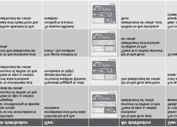
Audio functions
Audio system controls
1. VOLUME dial
2. AM/FM - select a radio band
3. MODE - select a sound source
4. TUNING dial
5. SOUND button
Selecting a sound source
Press AM/FM (2) repeatedly to toggle between FM1, FM2, and AM. Press MODE (3) repeatedly to toggle between the CD player and the optional external sound source AUX or the
optional Sirius satellite radio.
The currently selected sound source will be shown in the display.
AUX The AUX (auxiliary) port, located under the center armrest, can be used to connect for example, an mp3 player.
If the player is being charged through a 12-volt socket while it is connect to the AUX port, sound quality may be impaired.
The volume of the external sound source AUX may be different from the volume of the internal sound sources such as the CD player or the radio. If the external sound source's volume is too high, the quality of the sound may be impaired.
This can be prevented by adjusting the external sound source's input volume.
1. While playing the radio or a CD, lower the audio volume to about one-quarter.
2. Switch to AUX mode on the audio system.
3. Connect the headphone output from your music player to the AUX input using a cable with a stereo 3.5mm mini- plug at both ends.
4. Set your music player's headphone volume to three-quarters using the player's volume controls.
5. Press Menu on the audio system, and navigate to AUX Volume or AUX Input Volume.
6. Turn the volume knob to raise or lower the AUX Input Volume until you hear music at a comfortable level.
229 10 Audio
Audio functions
7. If there is distortion, lower your music player's headphone volume until the distortion goes away.
8. Finally, exit the menu and adjust the audio volume to a comfortable level.
Volume Use the volume dial (1) or the buttons in the optional steering wheel keypad to adjust the volume level. The volume level is also adjusted automatically according to the vehicleÕs speed, see page 232 for more information on this function.
Steering wheel keypad
The four buttons on the steering wheel keypad can be used to control the audio system. The steering wheel keypad can be used to adjust volume, shift between preset stations and change CD tracks. Press one of the two left-hand buttons briefly to change to the next/previous preset radio station, or to go to the next/previous track on a CD. Press and hold down these buttons to search within a track on a CD.
Daytime/twilight display In daylight the information is displayed against a light background. In darkness it is displayed against a dark background.
230 10 Audio
Audio functions
USB/iPOD connector (option)
An auxiliary device, such as an iPOD or a USB flash drive can be connected to the audio system via the connector in the center console storage compartment.
A sound source must be chosen, depending on the device that has been connected:
1. Use MODE to select iPOD or USB. The text CONNECT DEVICE will be displayed.
2. Connect the device to the connector in the center console storage compartment (see the illustration).
The text LOADING will be displayed while the system indexes the files on the device. This may take a short time.
When indexing has been completed, track information will be displayed, and the desired track can then be selected.
Tracks can be selected in two ways:
Turn the Tuning knob (no. 4 in the illustration on page 228) clockwise or counterclockwise Use the right or left arrow keys on the navigation control (no. 5 in the illustration on page 233) to select the desired
track. The arrow keys on the steering wheel keypad can also be used in the same way.
NOTE
The system supports playback of files in the most common versions of formats such as mp3, wma, and wav. However, there may be versions of these formats that the system does not support.
USB flash drive To simplify the use of a USB flash drive, it is advisable to only store music files on the drive. It will take considerably longer for the system to index the files on the drive if it contains anything other than compatible music files.
MP3 player Many mp3 players have a file indexing system that is not supported by the vehicle's audio system. In order to use an mp3 player, the system must be set to USB Removable device/Mass Storage Device.
iPod An iPod receives current and its battery is charged through the connecting cord. However, if the iPOD's battery is completely drained, it should be recharged before the iPOD is connected to the audio system.
NOTE
When an iPOD is used as a sound source, the vehicle's audio system has a menu structure similar to the one in the iPOD. See the iPOD's manual for detailed information.
For further information, refer to the accessory manual USB/iPOD Music Interface.
Sound settings
Optimal sound reproduction The audio system is calibrated for optimal sound reproduction through the use of digital signal processing. This calibration takes into account the speakers, amplifier, cabin
231 10 Audio
Audio functions
acoustics, the seating position of the listener, etc., for each combination of vehicle and audio system. There is also dynamic calibration that takes into account the setting of the volume control, radio reception, and the vehicle's speed. The sound settings described in this manual, such as BASS, TREBLE, and EQUALIZER are only intended to enable the user to adapt sound reproduction to his/her personal preferences.
1. Press SOUND (5). Press this button repeatedly until you come to the setting that you wish to change.
2. Turn the TUNING dial (4) to make the desired setting.
The following settings can be made:
BASS-set the bass level
TREBLE-set the treble level
BALANCE-set the left/right sound balance
FADER-set the front/rear sound balance
CENTER1-make settings for the center speaker
SURROUND1-make settings for surround sound
1Dynaudio Sound System only
Surround sound
Surround sound settings are used to balance sound levels throughout the vehicle. Surround settings for the various sound sources are made separately.
NOTE
Dolby Surround Pro Logic II is only available on the Dynaudio Sound system. When listening to FM radio stations, Dolby Surround Pro Logic II functions best in areas with strong reception. If
reception is weak, selecting 2 or 3-channel stereo may provide better sound quality.
The Dolby symbol will be appear in the display when Dolby Pro Logic II is activated.
There are three alternative settings:
Pro Logic II 3-channel Off (normal 2-channel stereo)
Activating/deactivating Surround sound 1. Press MENU followed by ENTER.
2. Select AUDIO SETTINGS in the menu and press ENTER.
3. Select Surround FM/AM/CD/AUX and press ENTER.
4. Select PRO LOGIC II, 3-channel stereo or OFF and press ENTER.
Equalizer Front/Rear
This function is used to fine-tune the sound level for different frequencies separately.
NOTE
This function is only available on certain sound systems.
To adjust the equalizer settings:
1. Press MENU followed by ENTER.
2. Select AUDIO SETTINGS in the menu and press ENTER.
3. Select EQUALIZER FRONT/REAR and press ENTER.
The column in the display indicates the sound level for the current frequency.
Adjust the level with the TUNING dial (4), or use the Up/Down arrows. Additional frequencies can be selected
with the Right/Left arrows.
232 10 Audio
Audio functions
Save the settings by pressing ENTER or exit without saving by pressing EXIT.
Automatic sound control The audio system's volume is adjusted automatically according to the speed of the vehicle. There are three settings available, which determine the level of volume compensation:
LOW MEDIUM* HIGH
* Default setting.
To set the automatic sound level:
1. Press MENU followed by ENTER.
2. Select AUDIO SETTINGS in the menu and press ENTER.
3. Select AUTO. VOLUME CONTROL in the menu and press ENTER.
4. Select LOW, MEDIUM, or HIGH and press ENTER.
233 10 Audio
Radio functions
Radio function controls
1. AM/FM1/FM2 selection
2. Station preset buttons
3. TUNING dial for selecting radio stations
4. SCAN
5. MENU NAVIGATION CONTROL-press the up or down arrow keys to scroll in a menu, or the keys on the left/right sides of the control to search for or change radio stations/CD tracks
6. EXIT-press to cancel a menu selection or a selected function
7. AUTO-search for and store the strongest radio stations in the area in which you are driving
Searching for stations There are two ways to manually tune a radio station:
1. Turn the TUNING dial (3) to the desired frequency.
2. Press the left or right arrow key on the MENU NAVIGATION CONTROL and hold it down. The radio scans slowly in the selected direction and will increase the scanning speed after a few seconds. Release the button when the desired frequency appears in the display.
The frequency can be fine-tuned by short presses on the left/right arrow keys.
Storing preset stations
Manually storing a station 1. Tune to the desired station.
2. Press and hold the preset button under which the station is to be stored. The audio system sound will be interrupted for a few seconds and STATION STORED will appear in the display.
NOTE
A total of 30 stations can be stored; 10 stations each in AM, FM1 and FM2.
Automatically storing a station Pressing AUTO (7) automatically searches for and stores up to ten strong AM or FM stations in a separate memory. If more than ten stations are found, the ten strongest ones are stored. This function is especially useful in areas in which you are not familiar with radio stations or their frequencies.
To use the AUTO function:
1. Select a waveband using the AM/FM button (1).
2. Start the search by pressing AUTO until AUTO STORING appears in the display.
When the search is completed, AUTO STORING will no longer be displayed If there are no stations with sufficient signal strength, NO AST FOUND is displayed.
The auto-stored stations can be selected using the preset buttons (2).
Press EXIT (6) to terminate the automatic storing function.
When the radio is in auto-store mode, AUTO is shown in the display. AUTO disappears when you return to normal radio mode, which can be done by briefly pressing AM/FM (1), EXIT (6), or AUTO (7).
234 10 Audio
Radio functions
To return to the Auto-store mode, press the AUTO button briefly and select a stored station by pressing one of the preset buttons (2).
Saving auto-stored stations in the preset memory An auto-stored station can be saved in the memory for manually preset stations.
1. Press AUTO (7) briefly.
2. Auto is displayed.
3. Press one of the preset buttons (2) under which the station is to be stored. Hold down the button until STATION STORED is displayed.
The radio will then exit auto-store mode and the stored station can be selected by pressing the preset button.
Scanning
SCAN (4) automatically searches through the selected waveband for strong AM or FM stations. When the radio finds a station, that station will be played for approximately 8 seconds, after which scanning resumes.
Activating/deactivating SCAN
1. Select radio mode using the AM/FM button (2).
2. Press SCAN to activate the function. SCAN is shown in the display.
3. Press the SCAN or EXIT button to deactivate the scan function and listen to the selected station.
Storing a station found with SCAN
A station can be stored as a preset while the SCAN function is activated.
Press one of the preset buttons (2) under which the station is to be stored. Hold down the button until STATION
STORED is displayed.
The SCAN function will be deactivated and the station can be selected by pressing the preset button.
Radio text
Certain stations broadcast program information, which can be shown in the display.
To start this function:
1. Select FM1 or FM2 and press the MENU button.
2. Press ENTER.
3. Select RADIOTEXT in the menu and press ENTER.
To deactivate this function, select RADIOTEXT again and press ENTER.
235 10 Audio
Sirius satellite radio (option)
Listening to satellite radio
The optional Sirius satellite system consists of a number of high elevation satellites in geosynchronous orbit.
NOTE
The digital signals from the Sirius satellites are line-of-sight, which means that physical obstructions such as
bridges, tunnels, etc, may temporarily interfere with signal reception.
Avoid any obstructions, such as metallic objects transported on roof racks or in a ski box, or other antennas that
may impede signals from the SIRIUS satellites.
Selecting Sirius radio mode 1. Press Power to switch on the audio system (see page 233 for information on the standard radio functions).
2. Press the MODE button repeatedly until Sirius 1 or 2 is displayed.
Activating Sirius radio 1. Tune to a satellite channel that has no audio, which means that the channel is unsubscribed and the text "CALL 888- 539-SIRIUS TO SUBSCRIBE" is displayed (see also "Selecting a channel" in the right column).
2. Call Sirius at 1-888-539-SIRIUS (7474).
3. When asked for the Sirius ID number press AUTO to display this number. It is also possible to retrieve the Sirius ID from the MENU.
4. "UPDATING SUBSCRIPTION" will be displayed while the subscription is being updated, after which the display will return to the normal view.
SIRIUS ID The SIRIUS ID is required when contacting the Sirius Call Center. It is used to activate your account and when making any account transactions. The SIRIUS ID is sometimes referred to as the Electronic Serial Number (ESN).
Selecting a channel category
1. Select Sirius radio mode as described above.
2. Press ENTER.
3. Use the up/down arrow keys to scroll through the list of categories.
4. Press ENTER or the right arrow key to select a category.
5. Use the left or right arrow keys to select a channel in the currently chosen category.
6. Press ENTER to listen to a channel.
The category "All" is default, which enables you to scroll through the entire list of available satellite channels.
The channel categories are automatically updated several times a year. This takes approximately two minutes and will interrupt normal broadcasting. A message will be displayed while updating is in progress. Information on channel or feature updates is available at www.sirius.com.
Selecting a channel There are three ways of tuning in a channel:
Using the left and right arrow keys By turning the tuning control Through direct channel entry
Direct channel entry The Sirius satellite channels are numbered consecutively throughout all of the categories. To access a channel directly:
1. Press MENU and scroll to "Direct channel entry."
2. Use the numerical keypad to enter the channel's number.
3. Press ENTER. The radio will tune to this channel, even if it belongs to a category other than the currently selected one.
236 10 Audio
Sirius satellite radio (option)
NOTE
The numbers of skipped or locked channels will not be displayed.
If a channel is locked, the access code must be entered before the channel can be selected. See "Unlocking a
channel" on page 237.
Scanning
NOTE
SCAN automatically searches through the list of satellite channels. See page 234 for more detailed information.
Storing a channel
A long press on one of the number keys stores the currently tuned channel on that key. A short press on a number key while the radio is in Sirius 1or 2 mode will tune to the preset satellite channel stored
on that button, regardless of the currently selected channel category.
Song Seek and Song Memory
The Song Seek and Song Memory functions provide both audio and visual notification when Sirius is broadcasting your favorite songs. Song Seek enables you to store the name of the song for future advance notification when that song is being played. The Song Memory feature makes it possible to view all of the current songs that are stored in memory.
Song memory Up to ten songs can be saved in the system's memory.
1. Press MENU.
2. Scroll to "ADD SONG TO SONG MEM." and follow the instructions shown in the display.
If a new song is selected when the memory is full, you will be prompted to press ENTER to delete the last song on the list.
NOTE
The remaining songs in the list will move down one position, and the newly added song will be placed at the top of the list.
Song seek When a satellite radio channel plays one of the songs stored in the song memory, the listener will be alerted by a text message and an audible signal.
Press ENTER to listen to the song or EXIT to cancel.
To activate/deactivate the song seek function:
1. Press MENU
2. Scroll to "SONG SEEK"
3. Press ENTER to activate or deactivate the function.
NOTE
When the song has ended, the radio will remain tuned to the channel on which the song was played.
Radio text The text that is displayed about the song that is currently playing can be changed. Use the AUTO button or the menu to display the ARTIST, TITLE, COMPOSER, or switch RADIO TEXT OFF.
237 10 Audio
Sirius satellite radio (option)
Advanced settings
This menu function enables you to make settings on certain Sirius satellite radio functions. To access this menu:
1. Press MENU.
2. Scroll to Sirius menu.
3. Select ADVANCED SIRIUS SETTINGS.
WARNING
Settings should be made when the vehicle is at a standstill.
The following settings can be made in the Sirius menu.
Songs can be added to the song list Channel skip settings can be made Channel lock settings can be made The channel access code can be displayed or changed Your Sirius ID can be displayed
Skip options This function is used to remove a channel from the list of available channels.
Skip current 1. Select CHANNEL SKIP LIST and press ENTER.
2. Select a category in the list and press ENTER.
3. Skip channels in the list presented by pressing ENTER or right arrow key.
Unskip all channels This permanently removes all channels from the skip list and makes them available for selection.
Temp. unskip all ch. This function will temporarily unskip all channels and make them available for selection. The channels remain on the skip list and will again be skipped the next time the ignition is switched on.
Channel lock Access to specific channels can be restricted (locked). A locked channel will not provide audio, song titles, or artist information.
NOTE
All channels are initially unlocked.
Locking a channel: 1. Select "SIRIUS ID" in the menu and select LOCK OPTIONS and press ENTER.
2. Select CHANNEL LOCK LIST and press ENTER
3. Enter the channel access code and press ENTER.
4. Select a category in the list and press ENTER.
5. Lock channels in the list presented by pressing ENTER or right arrow.
The channel is now locked and a checked box will be displayed to indicate this. It will be necessary to enter the channel access code1 in order to listen to a locked channel.
Unlocking a channel: A channel's access code1 is required to unlock a channel.
Unlock all channels This permanently removes all channels from the locked list and makes them available for selection.
Temp. unlock all ch. This function will temporarily unlock all channels and make them available for selection. The channels remain on the locked list and will again be locked the next time the ignition is switched on.
238 10 Audio
Sirius satellite radio (option)
CHANGE CODE This function makes it possible to change the channel access code. The default code is 0000.
To change the code:
1. Select CHANGE CODE and press ENTER.
2. Enter the current code and press ENTER.
3. Enter the code and press ENTER.
4. Confirm the new code and press ENTER.
If an incorrect code is entered, the text WRONG CODE! is displayed.
If you have forgotten the access code: 1. Select "SIRIUS ID" in the Sirius settings menu and press ENTER.
2. Press and hold the ENTER button for 2 seconds.
3. The current code will be displayed. Your Volvo retailer can also provide you with assistance.
SIRIUS ID This function displays the 12-digit Sirius activation ID.
239 10 Audio
CD player/CD changer (option)
CD function controls
1. MENU NAVIGATION CONTROL-press the up or down arrow keys to scroll in a menu, or the keys on the left/right sides of the control to change CD tracks/fast forward/back
2. Buttons for selecting a disc in the optional CD changer
3. CD eject button
4. CD slot
5. MODE button
6. TUNING dial for selecting tracks
Playing a CD
Single CD player Start the CD player by pressing the MODE button (5) and inserting a disc in the slot (4). If there is already a disc inserted, it will begin to play.
NOTE
If a CD is in the slot when the audio system is in CD mode, the CD will be played automatically.
CD changer The CD changer can hold up to six discs.
1. Start the CD changer by pressing the MODE button (5).
2. Select an empty position using the 1-6 buttons or the up/down keys on the MENU NAVIGATION CONTROL. The display shows which positions are empty.
3. Insert a disc into the slot (4).
CAUTION
Ensure that INSERT DISC is displayed before inserting a disc. If a CD position in the changer containing a disc is selected, and the audio system is in CD mode when it is
switched on, the CD will play automatically.
CD eject Eject from Single CD player
Press the eject button (3) to eject the disc.
Eject from CD changer This function makes it possible to eject a single disc, or to eject all of the discs in the changer.
Press the eject button (3) briefly to eject the disc that is currently playing.
240 10 Audio
CD player/CD changer (option)
A longer press (more than two seconds) starts the process of ejecting all of the discs in the changer.
NOTE
The EJECT ALL function can only be used while the vehicle is at a standstill and will be cancelled if the vehicle
begins to move.
For reasons of traffic safety, the ejected CD must be removed within 12 seconds or it will be automatically drawn
back into the slot and the CD player will enter pause mode. Press the CD button to restart the disc.
CD Pause When the audio system volume is turned off completely, the CD player will pause and will resume playing when the volume is turned up again.
Audio files In addition to playing normal music CDs, the CD player/changer can also play discs containing files in mp3 or wma format.
NOTE
Certain discs that are copy protected cannot be read by the player.
When a disc with audio files is inserted in the player, the player scans the disc's folders before it begins playing the files. The length of time that this takes depends on the quality of the disc.
Navigating the disc and playing tracks If a disc with audio files is in the CD player, press ENTER to display a list of folders on the disc.
Use the up and down arrows in the navigation control (see the illustration on page 239) to move among the folders on the disc. Audio files have the symbol and folders containing these files have the symbol. Press ENTER to play a selected folder or a file.
When the music file has been played, the player will continue to play the rest of the files in the current folder. When all of the files in the folder have been played, the player will automatically go to the next folder and play the files in it.
Press the left or right arrow key on the navigation control if the entire name of the current track does not fit in the display.
Changing tracks Briefly press the left or right arrow keys on the MENU NAVIGATION CONTROL to skip to the previous or next track/file.
NOTE
The TUNING dial (6) (turn clockwise to go to the next track/file, or counterclockwise to go to the previous track/file) or the optional steering wheel keypad can also be used for this purpose.
Fast forward/back Press and hold down the left or right arrows keys in the MENU NAVIGATION CONTROL (or the corresponding keys on the optional steering wheel keypad) to search within a track/file or the whole disc. The search continues for as long as the buttons are held down.
Random play This function plays the tracks/files on a CD (or on all of the CDs if the vehicle is equipped with the optional CD changer) in random order (shuffle).
241 10 Audio
CD player/CD changer (option)
Activating/deactivating the random function-CD player
If a normal CD is being played: 1. Press MENU followed by ENTER.
2. Select Random and press ENTER.
If a CD with audio files is being played: 1. Press MENU followed by ENTER.
2. Select RANDOM and press ENTER.
3. Select DISC or FOLDER and press ENTER.
Activating/deactivating the random function-CD changer If a normal CD is being played: 1. Press MENU followed by ENTER.
2. Select RANDOM and press ENTER.
3. Select SINGLE DISC or ALL DISCS and press ENTER.
If a CD with audio files is being played: 1. Press MENU followed by ENTER.
2. Select RANDOM and press ENTER.
3. Select SINGLE DISC or FOLDER and press ENTER.
NOTE
CD changer only-you can only select the next random track/file on the current disc.
Press the EXIT button to stop random play. The random function is automatically deactivated when another disc is selected.
Disc text (CD changer only) Certain CDs contain information about the disc, such as the titles of the tracks, etc. This information can be shown in the display by activating the DISC TEXT function.
1. Press MENU. Select the menu for relevant sound source and press ENTER.
2. Select DISC TEXT in the menu and press ENTER.
3. If information is stored on the disc, it will now appear in the display.
To deactivate this function, select DISC TEXT in the menu and press ENTER.
Scan This function plays the first 10 seconds of each track/file on the CD.
Press SCAN. Press EXIT or SCAN to stop the scan function and listen to an entire track/file.
CD eject Single CD player Press the eject button (3) to eject the disc.
CD changer This function makes it possible to eject a single disc, or to eject all of the discs in the changer.
Press the eject button (3) briefly to eject the disc that is currently playing. A longer press (more than two seconds) starts the process of ejecting all of the discs in the changer.
NOTE
The Eject all function can only be used while the vehicle is at a standstill and will be cancelled if the vehicle
begins to move.
For reasons of traffic safety, the ejected CD must be removed within 12 seconds or it will be automatically drawn
back into the slot and the CD player will enter pause mode. Press the CD button to restart the disc.
Compact disc care
Keep the following in mind when playing/handling compact discs
Do not put tape or labels on the disc itself. They could become stuck in the player. CDR discs can cause listening problems due to the quality of the disc or recording equipment used.
242 10 Audio
CD player/CD changer (option)
DualDisc: The audio side of a DualDisc (combined CD/DVD) does not meet CD specifications and may not play in
your audio system.
Keep the discs clean. Wipe them with a soft, clean, lint-free cloth, working from the center outward. If necessary,
dampen the cloth with a neutral soap solution. Dry thoroughly before using.
Never use cleaning spray or antistatic liquid. Use only cleaners specifically made for CDs. Use discs of the correct size only (3.5" discs should never be used). Volvo does not recommend the use of plastic outer rings on the disc.
Condensation may occur on discs/optical components of the changer in cold winter weather. The disc can be dried
with a clean, lint-free cloth. Optical components in the CD changer may, however, take up to one hour to dry off.
Never attempt to play a damaged CD. When not in use, the discs should be stored in their covers. Avoid storing discs in excessive heat, direct sunlight or
in dusty locations.
243 10 Audio
Audio menu
FM1/FM2 menu
1. RADIOTEXT ON/OFF 2. ADVANCED RADIO SETTINGS 3. AUDIO SETTINGS
AM menu
1. 1. AUDIO SETTINGS
CD menu
1. RANDOM 2. AUDIO SETTINGS
CD changer menu
1. RANDOM 2. DISC TEXT ON/OFF 3. AUDIO SETTINGS
AUX menu
1. AUX VOLUME 2. SOUND SETTINGS
Contents | Top of Page
2 0 0 8
VOLVOC30
244 11 Specifications
246
Label information 248
Dimensions and weights 250
Fluid capacities 251
Engine oil 253
Engine specifications Electrical system 255
Three-way catalytic converter 257
258
Volvo programs245 11 Specifications
246 11 Specifications
Label information
247 11 Specifications
Label information
1. Model plate Vehicle Identification Number (VIN). Codes for color and upholstery, etc.
2. Federal Motor Vehicle Safety Standards (FMVSS) specifications (USA) and Ministry of Transport (CMVSS) standards (Canada) Your Volvo is designed to meet all applicable safety standards, as evidenced by the certification label on the facing side of the driver's door. For further information regarding these regulations, please consult your Volvo retailer.
3. Loads and Tire Pressures The appearance of the decal will vary, depending on the market for which the vehicle is intended. Canadian models: upper decal U.S. models: lower decal
4. Vehicle Identification Number (VIN)1
The VIN plate is located on the top left surface of the dashboard. The VIN is also stamped on the right hand door pillar.5. Vehicle Emission Control Information Your Volvo is designed to meet all applicable emission standards, as evidenced by the certification label on the underside of the hood. For further information regarding these regulations, please consult your Volvo retailer.
1 The Vehicle Identification Number (VIN) should always be quoted in correspondence concerning your vehicle with the retailer and when ordering parts.
248 11 Specifications
Dimensions and weights
Dimensions
CAUTION
The maximum permissible axle loads and/ or the gross vehicle weight must not be exceeded.
WARNING
When adding accessories, equipment, luggage and other cargo to your vehicle, the total capacity weight must not be exceeded.
249 11 Specifications
Dimensions and weights
Weights
250 11 Specifications
Fluid capacities
Specifications and capacities
NOTE
The transmission oil does not normally need to be changed during the service life of the vehicle. However, it may be necessary to replace the oil if the vehicle is often driven in areas of sustained temperature extremes (hot or cold), when towing a trailer over long distances, for prolonged driving in mountainous areas, or if the vehicle is often driven short distances in temperatures under 40°F (5°C).
251 11 Specifications
Engine oil
Oil specifications
Engine oil must meet the minimum ILSAC specification GF-3, API SL, or ACEA A1/B1. Lower quality oils may not offer the same fuel economy, engine performance, or engine protection.
Volume: 6.1 US qts (5.8 liters).
Volume between the MIN and Max marks on the dipstick: approximately 1.4 US qts (1.3 liters).
Volvo recommends Castrol.
Depending on your driving habits, premium or synthetic oils may provide superior fuel economy and engine protection. Consult a trained and qualified Volvo service technician for recommendations on premium or synthetic oils.
Oil additives must not be used.
NOTE
Synthetic oil is not used when the oil is changed at the normal service intervals. This oil is only used at customer request, at additional charge. Please consult a trained and qualified Volvo service technician.
Oil viscosity (stable ambient temperatures)
Operation in hot climates When temperatures exceed 104° F (40° C) in your area, Volvo recommends, for the protection of your engine, that you use a heavier weight oil, such as such as SAE 5W-40 or 0W-40. See the viscosity chart.
Operation in temperate climates Incorrect viscosity oil can shorten engine life. Under normal use when temperatures do not exceed 104° F (40° C), SAE 5W-30 will provide good fuel economy and engine protection. See the viscosity chart.
Extreme engine operation Synthetic oils meeting SAE 0W-30 or 0W-40 and complying with oil quality requirements are recommended for driving in areas of sustained temperature extremes (hot or cold), when towing a trailer over long distances, and for prolonged driving in mountainous areas.
252 11 Specifications
Engine oil
American Petroleum Institute (API) symbol The API Service Symbol "donut" is divided into three parts:
The upper section describes the oil's performance level. The center identifies the oil's viscosity. The lower section indicates whether the oil has demonstrated energy-conserving properties in a standard test in
comparison to a reference oil.
253 11 Specifications
Engine specifications
1Certain markets only
2The engine specifications for horsepower and torque listed in this table are based on the use of premium fuel.
254 11 Specifications
Engine specifications
Charge air cooler (Intercooler) Turbocharged engines employ a turbo-compressor to force air into the engine inlet manifold and a charge air cooler to cool the compressed inlet air. The resulting increase in air flow raises pressure in the intake manifold and increases engine power over that developed by the normally-aspirated engine. The charge air cooler (which resembles a radiator) is located between the turbo-compressor and inlet manifold.
Fuel system The engine is equipped with a multiport fuel injection system.
255 11 Specifications
Electrical system
General information
12-volt system with voltage controlled generator. Single wire system in which the chassis and engine block are used as conductors, grounded on the chassis.
Battery
1Models equipped with the High Performance audio system 700 A2
2Models equipped with the Premium Sound audio system, the Volvo Navigation System and/or keyless drive
If the battery must be replaced, replace it with one with the same cold start capacity and reserve capacity as the original (see the decal on the battery).
WARNING
PROPOSITION 65 WARNING! Battery posts, terminals, and related accessories contain lead and lead compounds, chemicals known to the state of California to cause cancer and reproductive harm. Wash hands after handling.
256 11 Specifications
Electrical system
Bulbs used in the car
257 11 Specifications
Three-way catalytic converter
Three-way catalytic converter - general information
Keep your engine properly tuned. Certain engine malfunctions, particularly involving the electrical, fuel or distributor ignition systems, may cause unusually high three-way catalytic converter temperatures. Do not continue to operate your vehicle if you detect engine misfire, noticeable loss of power or other unusual operating conditions, such as engine overheating or backfiring. A properly tuned engine will help avoid malfunctions that could damage the three-way catalytic
converter.
Do not park your vehicle over combustible materials, such as grass or leaves, which can come into contact with the hot
exhaust system and cause such materials to ignite under certain wind and weather conditions.
Excessive starter cranking (in excess of one minute), or an intermittently firing or flooded engine can cause three-way
catalytic converter or exhaust system overheating.
Remember that tampering or unauthorized modifications to the engine, the Electronic Control Module, or the vehicle
may be illegal and can cause three-way catalytic converter or exhaust system overheating. This includes: - Altering fuel injection settings or components. - Altering emission system components or location or removing components. - Repeated use of leaded fuel.
NOTE
Unleaded fuel is required for vehicles with three-way catalytic converters.
258 11 Specifications
Volvo programs
Volvo On Call Roadside Assistance
Your new Volvo comes with a four year ON CALL roadside assistance. Additional information, features, and benefits are described in a separate information package in your glove compartment. If you have misplaced your package, dial: In the U.S.A. 1-800-638-6586 (1-800-63-VOLVO) In Canada: 1-800-263-0475
Technician certification
In addition to Volvo factory training, Volvo supports certification by the National Institute for Automotive Service Excellence (A.S.E.). Certified technicians have demonstrated a high degree of competence in specific areas. Besides passing exams, each technician must also have worked in the field for two or more years before a certificate is issued. These professional technicians are best able to analyze vehicle problems and perform the necessary maintenance procedures to keep your Volvo at peak operating condition.
259 11 Specifications
This page left intentionally blank.
Contents | Top of Page
260- 265 12 Index
12 volt socket Air conditioning Air distribution, climate system Air vents, climate system Airbag system Airbags front side impact Alarm panic Alarm system Anchoring loads Anti-lock brakes warning light Approach lighting Audio system AUX port CD player controls menus playing audio files radio function controls Sirius satellite radio sound settings steering wheel keypad surround sound USB/iPOD connector Automatic Locking Retractor Automatic transmission shiftlock override Auxiliary connector (audio) Auxiliary equipment Battery maintenance
2 0 0 8
VOLVOC30
70
86 , 90, 93
95
88
1819, 20, 21
25
118
128, 129
112
6, 148
53
78228
239
228
243
240
233
235
230
229
230
230
32
145, 146
147
228
70208
replacing specifications warning symbols Blind Spot Information System (BLIS) Booster cushions Brake fluid Brake lights Brake system warning light Bulbs list of replacing Capacities Cargo area lighting load anchoring eyelets net Cargo area cover hard soft Catalytic converter CD player Central locking system immobilizer locking and unlocking the vehicle from the inside panic alarm remote control Chains (winter driving) Changing a wheel Check engine light Child restraints booster cushions convertible seats infant seats introduction ISOFIX/LATCH anchors recalls and registration top tether anchors Child safety Climate system air distribution air vents electronic climate control
209
255
209
156, 157, 158
40
206
58
148
55256
211250
102
112
112110
111
257
239116
126
118
116, 117
177
182
5340
37, 38, 39
35, 36
33, 34
41
43
42
3195
88
92, 93, 94general information manual functions personal settings refrigerant Clock setting Coat hanger Cold weather precautions Collisions, driving after Compass Convertible seats Coolant Courtesy lighting Crash mode Cruise control Cup holders Dimensions Disabling the passenger's side front airbag Dome lighting Door mirrors Door open warning light Driving after a collision Driving through water Dynamic Stability Traction Control (DSTC) Economical driving Electrical current, conserving Electronic Climate control Emergency Locking Retractor Emergency towing Emission inspection readiness Engine specifications starting starting with keyless drive Engine compartment location of components Engine oil checking specifications Environment Eyelets, load anchoring Federal Clean Air Act Floor mats cleaning
86, 87
89, 90
86
86
77
105
133
30
72, 73
37, 38, 39
205
102
30
66
106248
22, 23
102
74
55
30
133
150, 151132
134
92, 93, 94
32
152
200253
141
143
202203
251
112198
192warning Fluid capacities Fluids Front airbags Front fog lights Front passenger's side airbag, disabling Front seats manual adjustment power Fuel filler cap Fuel filler door unlocking Fuel level warning light Fuel requirements Fuses Geartronic automatic transmission shiftlock override Generator warning light Glove compartment locking/unlocking Hazard warning flashers Headlights high beams low beam washers Home Link® Universal Transceiver Home safe lighting Hood opening Ignition switch Immobilizer Infant seats Inflatable Curtain Inflation pressure Inflation pressure tables, Canadian models Inflation pressure tables, U.S. models Information display messages Inspection readiness Instrument and warning symbols Instrument overview Instrument panel lighting
141
250
206
19, 20, 21
58
22, 2398
99, 100, 101
59
53
136, 137, 138
219 - 224145, 146
147
54
105
12768
60
60
63
80, 81, 82
60
201139
116
35, 36
26, 27
168
171
170
56, 57
200
51, 52, 53
47, 48
49, 50
58Interior lighting iPOD connector (audio system) ISOFIX anchors Jack attaching location of Jacket hanger Jump starting Key blade Keyless drive location of antennas (pacemaker warning) locking and unlocking the vehicle starting the engine Keylock Keypad (steering wheel) Label information LATCH anchors Leather care Liftgate wiper Lighting panel Loading the vehicle Loads, transporting Locking the vehicle from the inside Long distance trips Low beam headlights Maintenance battery performed by owner Malfunction indicator light Manual transmission 6-speed Mirrors power door rearview vanity Moonroof MP3 files, playing Occupant safety Occupant Weight Sensor (OWS)
102
230
41182, 183
181
105
154119, 120
125
122, 123, 124
143
229246, 247
41
190
64
58
155
155
117
126
134
60208
199
53
14474
72
103
75, 76
24012
22, 23Octane ratings Oil checking specifications Oil pressure warning light Owner maintenance Pacemaker (keyless drive warning) Paint color code touching up Panic alarm Park assist Parking brake Hand brake indicator light Parking lights Passenger's side front airbag, disabling Personal settings approach lighting autolock climate system settings home safe lighting keyless drive settings lock confirmation unlock settings Polishing the car Power door mirrors Power front seats Power steering fluid Power windows Proposition 65 warning Radio function controls Rain sensor READ button (information display) Reading lights Rear fog light indicator light Rear liftgate replacing wiper blade Rear liftgate wiper Rear seat accessing armrest
136
203
251
54
199125
193
193
118
160, 161, 16269
54
58
22, 2378
77
78
78
78
77
77
189
74
99, 100, 101
206
71
6, 154, 208233
64
56
102
58
53
207
6498
10913
12
235116
119, 120
118
13
12
258
180108
72
72, 73
43
136, 138
137
43folding backrests Rearview mirror compass Recalls, child restraints Refueling fuel filler door Registering child restraints Remote control central locking system key blade replacing batteries Reporting safety defects in Canada Reporting safety defects in the U.S. Roadside assistance Rotating tires Safety defects in Canada, reporting Safety defects in the U.S., reporting Satellite radio Seat belts Automatic Locking Retractor/Emergency Locking Retractor 32
buckling/unbuckling 14
192
cleaning 17
guides maintenance 16
14
pretensioners 16
reminder reminder light 54
15
use during pregnancy 15
use with child seats using 14
98, 99, 100, 101
Seats front 6, 141
Shiftlock override 147
25
Side impact protection airbags 235
Sirius satellite radio Snow chains 177
177
Snow tires 178, 181
Spare tire Stability system indicator light 53
116
Start inhibitor 141
Starting the engine with keyless drive 143
Steering wheeladjustment keypad lock Storage compartments Sunroof (moonroof) Supplemental restraint system warning light Three-way catalytic converter Tire pressure monitoring system Tires changing designations general information glossary of tire terminology inflation pressure inflation pressure table, Canadian models inflation pressure table, U.S.models rotation snow chains spare spare tire storing studded tires switching (summer and winter) temporary spare tire pressure monitoring system tread wear indicator uniform quality gradings vehicle loading Top tether anchors Towing Transmission automatic manual, 6-speed Transporting loads Tread wear indicator Trip computer Turn signals indicator lights using Uniform quality gradings (tires) Unlocking the vehicle from the inside
68
229
139
104, 105
75, 76
18
54257
184182
172
166, 167
174
168
171
170
180
177
178
181
166
177
180
178
184, 185
166
176
175
42
152145
144
155
166
61, 6254
60176
126Upholstery care USB connector (audio system) Vanity mirror Vehicle dimensions Vehicle Event Data Vehicle loading Vehicle weights Volvo and the environment Volvo Inflatable Curtain Volvo On Call Roadside Assistance Warning flashers Warning symbols Warranties Washer fluid Washing the car Water, driving through Waxing the car Weights Wheels changing cleaning chromed wheels nuts storing Whiplash Protection System (WHIPS) Windows, power Windshield rain sensor replacing wiper blades washers wipers Winter tires Wiper blades, replacing Wiper, liftgate WMA files, playing
190
230103
248
198
155, 175
249
26, 27
25868
51, 52, 53
198
199
188
131
189
249182
189
179
166
28, 29
7164
207
63
63
177
207
64
240Contents | Top of Page
2 0 0 8 VOLVO
C30
VOLVO OWNER'S MANUAL C30
Welcome to the worldwide family of Volvo owners. We hope that you will enjoy many years of safe driving in your Volvo, an automobile designed with your safety and comfort in mind. To help ensure your satisfaction with this vehicle, we encourage you to familiarize yourself with the equipment descriptions, operating instructions and maintenance requirements/recommendations in this manual. We also urge you and your passengers to wear seat belts at all times in this (or any other) automobile. And, of course, please do not operate a vehicle if you may be affected by alcohol, medication or any impairment that could hinder your ability to drive.
Your Volvo is designed to meet all applicable safety and emission standards, as indicated by the certification labels attached to the driver's door opening, and on the underside of the hood.
For further information please contact your retailer, or:
In the USA: Volvo Cars of North America, LLC Customer Care Center P.O. Box 914 Rockleigh, New Jersey 07647-0914
1-800-458-1552
www.volvocars.usIn Canada: Volvo Cars of Canada Corp. National Customer Service 175 Gordon Baker Road North York, Ontario M2H 2N7
1-800-663-8255
www.volvocanada.com2007 © Volvo Car Corporation. All rights reserved.
2 Contents
00 Introduction General information Volvo and the environment 7
Important warnings01 Safety Occupant safety Reporting safety defects Seat belts Supplemental Restraint System Front airbags Occupant Weight Sensor (OWS) Side impact protection airbags Volvo Inflatable Curtain (VIC) Whiplash Protection System Crash mode Child safety Child restraint systems Infant seats Convertible seats Booster cushions ISOFIX lower anchors Top tether anchors Child restraint registration and
12
13
14
18
19
22
25
26
28
30
31
33
35
37
40
41
4202 Instruments and control Instrument overview Instrument panel Instrument and warning symbols Information display Lighting panel Left-side steering wheel lever Trip computer (option) Right-side steering wheel lever Cruise control (option) Steering wheel adjustment, Hazard warning flashers Parking brake 12-volt sockets Power windows Mirrors Power moonroof (option) Personal settings Home Link® Universal
46
49
51
56
58
60
61
63
66
68
69
70
71
72
75
77
80recalls
43 Transceiver (option)
3 Contents
03 Climate system