- Download PDF Manual
-
Downloaded from www.Manualslib.com manuals search engine
Service. The Passat ‘97 Construction and operation 191 640.2810.10.00Technical Status: 09/96 The Presentation Only for internal use.© VOLKSWAGEN AG, WolfsburgAll rights reserved. Subject to modification. ` Printed on chlorine-free bleached paper. Self Study ProgrammeService Department Downloaded from www.Manualslib.com manuals search engine
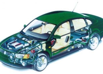
2 The most remarkable features of the new Passat are its: l High economy l Dynamic body styling l High-quality interior equipment designed with great attention to detail l Pioneering safety engineeringIn this booklet, we would like to provide you with an initial overview showing how we justify making these claims. 191/01 Downloaded from www.Manualslib.com manuals search engine
3 Page The Passat ‘9704Environmental Protection and Recycling08Body10Vehicle Safety 15Engines and Gearboxes19Running Gear26Brakes29Steering30Electrics31Extended Systems36 The Self Study Programme is not a Workshop Manual.Please refer to the relevant Service Literature for all inspection, adjustment and repair instructions. New Important ! / Note Downloaded from www.Manualslib.com manuals search engine
4 To avoid confusion, concise examples are used to illustrate the various aspects of this all-embracing vehicle concept.You can find detailed information in Self Study Programme No. 192 Passat ‘97 – The Enginee-ring. The Passat ‘97 191/86191/73 Service.192Der Passat '97Die TechnikKonstruktion und FunktionSelbststudienprogrammKundendienst Downloaded from www.Manualslib.com manuals search engine
5 Dimensions and Weights 4675 mm2707 mm1740 mm Track widths frontrear14981500mmmm 191/71 Weights Unladen weightMax. permissible weightappr. 1200appr. 1805kgkg Downloaded from www.Manualslib.com manuals search engine
6 The Platform - an Advantage for Workshops The term “platform” is frequently used in publications although its fundamental meaning is not explained. The result of this is that people are often unsure of what the term “platform” implies.The vehicle consists of a) the platform and b) the body.Design and vehicle characteristics dictate what form the body takes. In the eyes of the customer, the body characte-rises the styling of the vehicle as a whole. The Passat ‘97 The platformThe body The Passat ‘97 191/44191/76 Downloaded from www.Manualslib.com manuals search engine
7 The advantages for workshops like yourself are: -More clarity as regards the spare parts situation-Simplified inventory management-Fewer different special tools and fixtures-Easier assembly and repair Platform The platform comprises both common parts and system parts. Common parts e.g. sliding sunroof, steel rimCommon parts may only be used in platform vehicles without change.They do not influence the design of the vehicle. System parts e.g. seatSome system parts are identical.They have to be adapted since they are the interface between the platform and body. Common part Frame Adapted part Vehicle-specific seat uphol-stery, seat cover, etc. 191/90 System part Downloaded from www.Manualslib.com manuals search engine
8 Environmental Protection and Recycling The concept of eco-friendliness was pursued consistently throughout development of the new Passat.We would now like to show you some aspects of this topic which are also of interest to work-shops. Recycling Not least the recycling requirements present workshops with problems such as identifying, presorting and storing materials and waste operating media. To achieve this, the following measures were taken: l Identification of plastic part materials l Fewer composite materials l Reduction in fine sealing through the use oflaser welding l No parts containing CFCs are used. Take bumpers for example: Bumpers were previously manufactured from composites. What the term “composite” means is that different materials are combined with one another in such a way that subse-quent separation into clean material streams is no longer possible.If a plastic is to be recovered for recycling, it should, if possible, be sorted according to type for recycling purposes. This means that different types of plastic, for example, must not be mixed with one another.The bumpers on the Passat are recyclable because they do not contain composites. . Collection +sortingRecycled plastic Cleaning +recycling 191/67 Downloaded from www.Manualslib.com manuals search engine
9 Solvents Even during production, every effort is made to keep environmental pollution to a minimum. To achieve this, the following measures were taken: l Full galvanisation means much less wax and PVC underseal l Water-dilutable paints including water-based clear coat l Stringent requirements for materials ensurelower emissions in the vehicle interior Energy + Resources Raw materials and energy are in limited supply on the planet Earth. We must use them sparingly. To achieve this, the following measures were taken: l Less energy consumption during production through the use of new joining techniques (e.g. laser welding) and complete assemblies(e.g. side section of body), l Full galvanisation and an 11-year warrantyagainst corrosion perforation ensure highvalue retention and conservation of resources. Take laser welding for example: During laser welding, a highly concentrated light beam with a high energy content is used instead of a gas flame to join the components. No additional welding material is required, as is the case during MIG welding for example. Laser welded seams are extremely clean and do not need to be reworked.Laser welding offers a more favourable energy balance than conventional welding techniques. 191/03 Downloaded from www.Manualslib.com manuals search engine
10 Body The following will be of interest to you: l The Passat in the wind tunnel l Fully galvanised body l Greater body rigidity l Use of high-strength steel parts l Strategy of using common platform for bodyparts l Ease of repair demonstrated using door module as example l Rear collision demonstrated using bumperas example The Passat in the Wind Tunnel As you can see from the streamlines, the body of the new Passat is very aerodynamic.No turbulence, which increases aerodynamic drag, occurs.The new Passat has a drag coefficient of c d = 0.27, making it the best in its class.Accounting for the projected vehicle area (A) of 2.1 m 2 , aerodynamic drag is (Cd x A) = 0.567 m 2 . A = 2.1 m 2 191/02191/72 Downloaded from www.Manualslib.com manuals search engine
11 Fully-galvanised Body For the first time, the Passat has a fully galva-nised body which comes with an 11-year anti-corrosion perforation warranty.The drawing below shows you the parts which are hot-dip galvanised and those which are electrolytically galvanised.Surface patterns, which are also visible after painting, emerge during the hot-dip galvanisation process.That is why the outer skin of the body is electrolytically galvanised to produce a smooth finish. Electrolytically galvanisedHot-dip galvanised 191/70 Downloaded from www.Manualslib.com manuals search engine
12 Body Stability and Structure The Passat leads its class in terms of torsionalrigidity.This was achieved by using: l high-strength panels l different panel thicknesses l improved adhesive bonding techniques(e.g. adhesive joints)Adhesive joints increase rigidity and leakproofing while minimising noise levels. Downloaded from www.Manualslib.com manuals search engine
13 The Rear Bumpers Repairing damage to the rear bumperspreviously involved expensive repair and welding work, even after minor accidents.The bumpers on the Passat ‘97 have the capacity to absorb so much energy during a low-speed rear collision that only plastic parts have to be replaced. Time-consuming welding work is no longer necessary. High-strength Panels High-strength panels are used to produce a body with greater stability and strength and therefore to provide more safety for the vehicle occupants. They also substantially reduce the weight of the body-in-white.As you can see, the high-strength steel com-ponents in the front section of the vehicle create a cage-type structure to protect the vehicle occupants.The wings are also manufactured from high-strength steel. Advantages: -Less weight-Greater resistance to buckling-Higher strength 191/61 High-strength panelsAdhesive jointsLaser-weldedMash seam welded 191/46191/74 Downloaded from www.Manualslib.com manuals search engine
14 Body Body Platform The floorpan assembly, side members and luggage compartment floor assembly were adopted from the Audi A4 as a platform.To enhance ride comfort for rear-seat passengers, a steel floor plate 86 mmwide was inserted. +86 mm+86 mm New parts in Passat ‘97 191/69 Downloaded from www.Manualslib.com manuals search engine
15 Vehicle Safety As you will no doubt already know, we make a distinction between active and passive safety. Active safety Braking systemsSteeringRunning gearAirbag systemsRestraint systemsInside door panels and side trims with integral pelvis paddingsSafety bodySteering column The following features will be of interest to you: l Active and passive safety l ABS as standard l The Passat already complies with the new European standard for crashworthinesslDoor module with enclosed subframelDriver, front passenger and side airbagsas standardlNew seat belt tensioner with force limiterlInside door panels with pelvis paddingsPassive safety 191/75 Downloaded from www.Manualslib.com manuals search engine
16Vehicle Safety Crashworthiness The new Passat offers the driver and front pas-senger more safety, particularly during a side impact.The inside door panel, which is fitted complete with built-in door fittings, is bolted to the door. To protect the occupants, the inside door panel has an enclosed surface to prevent intrusion of the built-in door fittings into the interior of the vehicle.The side impact beams made of pressed sheet metal are arranged diagonally and glued to the outer panel to increase door rigidity.Impact energy can therefore be betterabsorbed, distributed and converted.Pelvis and rib paddings give the vehicle occupants added protection.The size of the overlap between the door and the sill, columns and side section has been increased.Deformation strength is increased due to the larger contact surface.Side impact beamPelvis paddingsInside door panelOverlap191/06191/07191/05Rib paddings Downloaded from www.Manualslib.com manuals search engine
17Airbag SystemsIn addition to the driver and front passenger airbags, the Passat is equipped with side air-bags as standard.Depending on the side and angle of impact, only the airbags in the immediate vicinity of the danger zone are inflated.Therefore, an uninflated airbag on the side facing away from the accident need not necessarily be defective.The driver and front passenger airbags, which have filling volumes of roughly 65 ltr. and 120 ltr. respectively, conform to the new internatio-nal-standard airbag sizes.The volume of the standard side airbag isroughly 12 litres.Side impact, right-hand sideHead-on colli-sionSide impact, left-hand side60$60$60$Detected by:crash sensor located beneath the left-hand seat and a safety sensorintegrated in the airbag control unitDetected by:crash sensor and asafety sensorintegrated in the airbagcontrol unitDetected by:crash sensor located beneath theright-hand seat and asafety sensorintegrated in the airbagcontrol unit191/04 Downloaded from www.Manualslib.com manuals search engine
18Vehicle Safety The Seat Belt TensionerThe pyrotechnical seat belt tensioner, together with the “belt fastened” sensor and belt force limiter, are combined in a single assembly.This compact design greatly simplifies replace-ment.The “belt fastened” sensor prevents the seat belt tensioner from being activated when the seat belt is not worn.191/17Seat belt tensionerBelt force limiter Downloaded from www.Manualslib.com manuals search engine
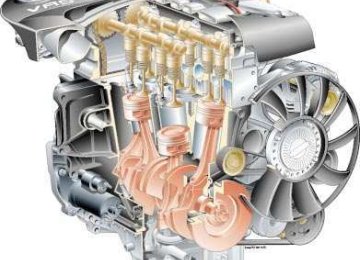
19Engines and Gearboxes1.6-ltr. Engine AHLDisplacement1595ccCompression ratio10.3 : 1Max. torque140 Nm at 3800 rpmMax. power output74 kW at 5300 rpmEngine managementSimos 2Fuel 95 RON unleaded premiumThis engine is also used in the Audi A3.It is mounted in the Passat without a twin-path intake manifold.1.8-ltr. 5V Engine ADRDisplacement1781 ccCompression ratio10.3 : 1Max. torque173 Nm at 3950 rpmMax. power output92 kW at 5800 rpmEngine managementMotronic M 3.8.2Fuel 95 RON unleaded premiumThis engine is also used in the Audi A6.In addition to the six tried and tested engines listed below, the new VR5 unit will also be mounted in the Passat.191/85191/77 Downloaded from www.Manualslib.com manuals search engine
20Engines and Gearboxes1.8-ltr. 5V Turbo Engine AEBDisplacement1781ccCompression ratio9.3 : 1Max. torque210 Nm at 1750-4600 rpmMax. power output110 kW at 5700 rpmEngine managementMotronic M 3.8.2Fuel 95 RON unleaded premiumThis engine is also used in the Audi A4.2.8-ltr. V6 Engine ACKDisplacement2771ccCompression ratio10.3 : 1Max. torque280 Nm at 3200 rpmMax. power output142 kW at 6000 rpmEngine managementMotronic M 3.8.2Fuel 98 RON unleaded premiumThis engine is also used in the Audi A6.191/31191/32 Downloaded from www.Manualslib.com manuals search engine
212.3-ltr. VR5 Engine AGZThe new VR5 engine has a displacement of 2.3 litres. It is derived from the VR6 engine and is designed for in-line or transverse mounting.Power output is 110 kW.The engineering of the VR5 engine is explained in a separate Self Study Programme.191/53 Downloaded from www.Manualslib.com manuals search engine
22Engines and Gearboxes1.9-ltr. TDI Engine AHUDisplacement1896 ccCompression ratio19.5 : 1Max. torque202 Nm at 1900 rpmMax. power output66 kW at 4000 rpmFuel 45 CN dieselMixture preparationDirect injection withelectronically controlleddistributor injectionpump1.9-ltr. TDI Engine AFNDisplacement1896 ccCompression ratio19.5 : 1Max. torque235 Nm at 1900 rpmMax. power output81 kW at 4150 rpmFuel 45 CN dieselMixture preparationDirect injection withelectronically controlleddistributor injectionpumpThis engine features a variable-rate turbocharger. You will find furtherinformation on this engine inSelf Study Programme SSP190.191/28191/28 Downloaded from www.Manualslib.com manuals search engine
23Range of Engines and Gearboxes012/01W01N01VSyncro1.6-ltr.74kW 1.8-ltr. 5V 92kW1.8-ltr. 5V turbo110kW2.3-ltr. VR5110kW1.9-ltr. TDI66kW1.9-ltr. TDI81kW2.8-ltr.V6 5V142kW 01V01AManual gearboxEnginesAutomatic gearbox191/64 Downloaded from www.Manualslib.com manuals search engine
24Engines and Gearboxes5-speed Manual Gearbox 012/01WThe 012/01W is a manual gearbox as used in the Audi A4.This gearbox has a magnesium housing for installation in the 1.6-ltr./74kW aluminium engine block.5-speed Manual Gearbox 01AThe 01A is the manual gearbox for four-wheel drive vehicles as used in theAudi A4.191/34191/35 Downloaded from www.Manualslib.com manuals search engine
254-speed Automatic Gearbox 01NThe 01N is also installed in the Audi A6, for example.You can find detailed information on this gearbox in Self Study Programe No. 172.5-speed Automatic Gearbox 01VYou will also be familiar with the 01V from the Audi A4.It is equipped with Tiptronic control as standard.You can find detailed information on this gearbox in Self Study Programme No. 180.191/36191/78 Downloaded from www.Manualslib.com manuals search engine
26Running GearIn addition to the four-link front suspension, we will show you on the following pages the newly developed torsion beam rear suspen-sion as well as the new double-wishbone rear suspension unique to Syncro models.The Four-link Front SuspensionThe four-link front suspension is standard in all front- and four-wheel drive vehicles.In the case of vehicles with tripoid joints, these joints can be repaired.Tripoid joint191/37 Downloaded from www.Manualslib.com manuals search engine
27The Torsion Beam Rear SuspensionSingle-tube damperCoil spring191/55Advantages of torsion beam rear suspension:-Larger through-loading width due to the factthat the coil springs and shock absorbers arekept physically apart-Use of single-tube dampers-Downward-facing V-section of axle beam-Self-aligning twin-grooved oblique ball bearings act as wheel bearings Downloaded from www.Manualslib.com manuals search engine
28Running GearThe Double-wishbone Rear SuspensionThe double-wishbone rear suspension was developed in order to provide a through-loading width of over 1000 mm.Engine power is transmitted to all four wheels by a Torsen differential.191/54 Downloaded from www.Manualslib.com manuals search engine
29BrakesThe Passat is equipped with the Bosch 5.3 anti-lock braking system as standard.Two different sizes of brake disc are available for the front axle. The rear suspensions also have disc brakes as standard.280 x 22 mm brake discThe front disc brakes are vented.The smaller disc diameter is based on a smaller vehicle mass and lower power output282.5 x 25 mm brake discThis disc brake is vented and larger in size.Rear brake caliperThe Passat has rear disc brakes.The brake caliper is made ofaluminium.Disc brakes, frontDisc brakes, rear191/16191/14 Downloaded from www.Manualslib.com manuals search engine
30SteeringHeight and Reach Adjustment of Steering ColumnThe Passat is equipped with power steering.The steering column can be adjusted manually 50 mm fore and aft and 28 mm for height.The steering column is attached to the body by a mounting pedestal with sliding guide.A damper element located above the double universal joint prevents vibrations and noise from being transmitted to the body.A clamped connection links the steering column to the power steering gear.Mounting pedestal withsliding guideDamper elementDouble universal jointClamped connection191/38You can find additional information on the steering in Self Study Programme SSP 167. Downloaded from www.Manualslib.com manuals search engine
31ElectricsThe following features will be of interest to you:lDecentralised vehicle electrical systemlDash panel insertlGas discharge headlightslWasher jetsDecentralised Vehicle Electrical SystemAdvantages:-Short wiring harnesses make cable connections easier to find and assign.-The short cables achieve substantial weight savings.-Test points can be assigned more easily.-The components of the vehicle electrical system are well protected against moisture.-The decentralised vehicle electrical systemresults in easier servicing.Example of the arrangementof control unitsABS control unitFuse carriers, located on side of dash panelAirbag control unitMaster control for extended central locking systemEngine control unitThe main feature of the decentralised vehicle electrical system is that the central electrics are subdivided into separate connector stations, relay carriers and fuse carriers. These submo-dules are arranged locally. This means that they are located close to the assemblies and functional units to which they belong. The functions of the “car” as an integrated system are divided up among several control units with specific tasks.Repair work on the vehicle electrical system may only becarried out using Wiring Harness Repair Kit VAS1978.191/43 Downloaded from www.Manualslib.com manuals search engine
32Electrics Dash panel insertThe following features will be of interest to you:lElectronic immobiliser integrated in dash panel insertlCapable of diagnosislCan be encodedlFuel gaugeThe dash panel insert is available in twoversions which differ from one another in terms of the displays in the centre of the dash panel insert.In vehicles equipped with a navigation system, this display is complemented by the Auto Check System with a multi-function display.The immobiliser is an integral feature of the dash panel insert. However, the matching functions of the immobiliser have been left unchanged.Self-diagnosis:The diagnostic functions can be retrieved using address word “17”.Both instruments can be encoded. This means that the dash panel insert can be encoded depending on country and engine configuration. It is also possible to enter the current mileage when the dash panel insert is replaced.Auto Check System with multi-function display191/79 Downloaded from www.Manualslib.com manuals search engine
33Fuel gaugeIn previous systems, the fuel gauge tended to fluctuate, e.g. when cornering. To counteract this, damping of the fuel gauge was increased using electronic devices.However, the drawback of this was that the fuel gauge took longer to display the correct fuel level after refueling.The new fuel gauge eliminates this drawback.If the ignition is switched off and fuel tank capacity increases by four litres or more, the newfuel level is recalculated and displayed straight after the ignition is restarted.If the ignition is switched on and the vehicle is stationary, the damping cuts out and the fuel level is displayed immediately.Do not refuel the vehicle with the ignition switched on.Fuel gaugewhen cornering (previously)Fuel gaugewhen cornering (today)Fuel gaugewhen refuelingDamping OnDamping Off191/51 Downloaded from www.Manualslib.com manuals search engine
341 Lux1 Lux050100150200250 mElectricsGas Discharge HeadlightsGas discharge headlights, which are integrated into the headlights, are available for the Passat as an option.However, the use of gas discharge technology is limited to the dipped beam headlight because it takes up to three seconds to achieve maximum luminous intensity. Therefore, H4 halogen lights will continue to be installed for the main beam headlight.Advantage of gas discharge headlights:-Greater luminous efficiency than conventional headlights-Better brightness distribution by virtue of alens-Fog light is no longer necessaryOn acount of the greater danger of dazzling oncoming traffic, vehicles with gas discharge headlights are equipped with dynamic head-light range control.Consequently, the switch for the manual head-light range control is not required.Electronic Headlight Range ControlThis function gathers its information on body tilt angle relative to the vehicle axes from two sensors located inside the front and rear wheel housings on the left-hand side of vehicle.191/80H4 halogen headlightsGas discharge headlights Downloaded from www.Manualslib.com manuals search engine
35Fan Jet NozzleThe Passat features new fan jet nozzles for washing the windscreens.Advantages:-Better fluid distribution over the entire surface of the windscreen-Lower water consumption-Better cleansing effect-No adjustment requiredMode of operationFor the sake of simplicity, the mode of opera-tion can be compared to that of a garden hose when it is swung from side to side.Moving the garden hose quickly produces a fan jet.A nozzle insert for producing the pendulum jet is integrated in the spray nozzle. It ensures a fan jet.A heated version of the spray nozzle is also available.Fan-type jetwith an opening angle of 45$ - 50$Installation from belowEngine bonnet191/82191/81 Downloaded from www.Manualslib.com manuals search engine
36Extended SystemsVarious systems cater for ride comfort and ease of operation in the new Passat.The following features will be of interest to you:llllExtended central locking system– Decentralised system conceptlHeater/air-conditioning– Innovations in the air-conditioninglNavigation + communications– Preparation for mobile cellular phoneExtended Central Locking SystemThe extended central locking system is based ona decentralised system concept. It has a central control unit and a separate door control unit with a control panel for every door.Self-diagnosis:Diagnosis is initiated using the address word “46”.Extended central locking system with four door control units191/62Master control units. Located in front of driver´s seat.Front door control unitsLocated on control panel on driver´s sideLocated on window lifter motor on front passenger sideRear door control unitsLocated on window lifter motors(available only in combination with elec-tric window lifters in rear doors) Downloaded from www.Manualslib.com manuals search engine
37fifiFunctions of the Extended Central Locking SystemThe master control unit assumes the following functionsRadio remote controlInterface to vehicle electrical systemAnti-theft warning systemwith “interior monitor” function Interior light controlCentral locking of rear doors (only in combination with mech. window lifters at rear)Central locking of boot lid191/45DiagnosisAddress word „46”Slide/tilt sunroofElectrically adjustable, folding and heated door mirrorsElectric window lifters withexcess power limitationCentral locking ofdoors, with Safe modeDiagnosisAddress word „46”The door control units assume the following functions Downloaded from www.Manualslib.com manuals search engine
38Extended SystemsThe heaterUnlike predecessor models, the new heater is constructed in one piece. The air distributing housing and the air duct with shutoff flap are combined in a single component.The heater, which is controlled at the air intake side, permits fresh-air and air-recirculation modes. A main shutoff flap is therefore no longer required.Central flapFresh-air/air-recirculation flap-By virtue of the stepped form of the central flap, the central air vent is closed indefrost mode.-An electric-motor-operated fresh-air/air-recirculation flap is integrated.-In defrost mode, the air recycle function is switched off.191/27191/48 Downloaded from www.Manualslib.com manuals search engine
39Operating and display unit with control unit-The controls have been rearranged.-The temperature sensor dash panel and blower is integrated in the operating and display unit.-The photosensor measures incident sunlight over a large area.There is greater sensitivity for controlling the interior climate.-Average outflow temperature is registered by a transmitter.The CLIMAtronicPleasant air-conditioning for comfort and safety in the Passat.AUTOECONCLIMAtronicTemperature sensor191/47 Downloaded from www.Manualslib.com manuals search engine
40Extended Systems-The fresh-air/air-recirculation flap iscombined with the back pressure flap.-Fresh-air blower with integratedcontrol unit.-The shape of the central flap has been modified to allow separate airflow to the central and side vents.-All flaps are electic-motor-operated.Air-conditioning without back pressure flap is installed in right-hand drive vehicles.The following components are integrated in the refrigeration circuit:- Plate evaporator- Controlled swash plate compressor- Condenser- Butterfly valve- Collecting vesselThe Air-conditioningCentral flapFresh-air blowerBack pressure flapFresh-air/air-recirculation flap191/42 Downloaded from www.Manualslib.com manuals search engine
41Navigation The navigation system enables the driver to reach his (her) destination easily and safely.It replaces the road map and enhancesroad safety.This system employs a map stored on aCD-ROM. The driver can select his (her) destination on this map.Directions for the driver are then given on the display in the dash panel insert and via the loudspeaker built into the control unit. The system comprises the following elements:-The navigation computer with integratedCD-ROM drive-The control unit with control and loudspeaker-The display integrated in the dash panelinsert-The earth magnetic field sensor-ABS wheel speed sensor-The sensor for the global positioningsatellite system (GPS)-The GPS satellite networkABS-control unitOperating unitDisplay indash panel insertABS wheel speed ssensorNavigation computerEarth magnetic field sensorGPS sensor191/66 Downloaded from www.Manualslib.com manuals search engine
42Extended SystemsNavigation computer with CD-ROM driveThe navigation computer determines the posi-tion of the vehicle by means of the above-men-tioned sensors. It then compares the calculated position with the map stored on the CD-ROM and the chosen destination.The computer then calculates directions for the driver from this comparison.Control unit with control and loudspeakerThe control unit is the interface to the navigation computer. The system is switched on or off and the destination is entered by ope-rating the control. In addition to the display integrated in the dash panel insert, a voice out-put can also be provided by means of thebuilt-in loudspeaker.Display integrated in dash panel insertThe navigation system displays information visually via the display of the Auto Check System with multifunction display integrated in the dash panel insert. Depending on selected function, the display shows a letter field for entering a destination or pictograms representing directions for the driver .191/50191/49191/83 Downloaded from www.Manualslib.com manuals search engine
43However, this particular navigation system is not yet able to make allowancefor traffic lights, one-way roads, building sites, traffic jams, etc.ABS wheel speed sensorThe wheel speed sensors of the rear suspension are used to provide the navigation computer with iinfomation on distance travelled.Earth magnetic field sensorThe earth magnetic field sensor determines the direction of travel relative to the north pole for the navigation computer.GPS sensorGPS stands for Global Positioning System, a global navigation system.The sensor is integrated in the roof aerial.The navigation computer uses the datasupplied by the GPS sensor as a correctionfactor or when relocating the vehicle if the computer loses track of the current position (e.g. during rail transport).191/84191/87191/88Connector GPS sensorBase of aerial Downloaded from www.Manualslib.com manuals search engine
44Extended SystemsAdvantage:-Easy to install-No complex cable installation necessary-One roof aerial for all functionsDepending on equipment specification ofthe vehicle, three types of aerial can be installed:-Radio only-Radio and telephone-Radio, telephone and navigation (GPS)With the cellular phone provision, only mobile phones with a VDA-standard connection can be operated.Cellular Phone Preparation Scope of cellular phone provision:-Hands-free microphone integrated in left-handA pillar-VDA-standard cable (standard connection for mobile phone)-Radio mute function-Change-over relay for left-hand doorloudspeaker-Combined roof aerial with high-frequency line to mobile phoneThe Passat is available with a mobile phone or cellular phone provision as equipment variants.Diagnositic connection191/68 Downloaded from www.Manualslib.com manuals search engine
45Notes Downloaded from www.Manualslib.com manuals search engine
46Notes Downloaded from www.Manualslib.com manuals search engine
47 Downloaded from www.Manualslib.com manuals search engine
Service. The Passat ‘97 Design and Function 192 640.2810.11.10Technical status: 11/96 The Engineering For internal use only. ¶ VOLKSWAGEN AG, WolfsburgAll rights reserved. Specifications subject to change. ` Printed on chlorine-freebleached cellulose paper. Self Study ProgrammeService Department Downloaded from www.Manualslib.com manuals search engine
2 The Passat ‘97 Having provided you with an initial overview of the new Passat in the Self Study Programme entitled “The Passat ‘97 – The Presentation”, we now want to describe in detail how the car’s various components are designed and how they function.The subjects of the VR5 engine, convenience electronics and navigation system are so wide-ranging that it would be beyond the scope of this Self Study Programme.We will therefore deal with them separately. SSP 192/107 Downloaded from www.Manualslib.com manuals search engine
3 Page Introduction04Vehicle Safety061.8-ltr. 5V Engine ADR201.8-ltr. 5V Turbo Engine AEB222.8-ltr. V6 Engine ACK261.9-ltr. TDI Engine AFN34Gearbox38Drive Shafts40Running Gear43ABS/EDL48Electrics55Air-conditioning60 This Self Study Programme is not a Workshop Manual!Please refer to the relevant Service Literature for all inspection, adjustment and repair instructions. New!Important! / Note! Downloaded from www.Manualslib.com manuals search engine
4 Engines Given that the engine concepts used in the Passat ‘97 are tried and tested, we will con-fine ourselves solely to special innovations such as the variable valve timing featured in the 2.8-ltr. V6 engine. Gearbox Non-ferrous metals, such as aluminium or magnesium, are being used increasingly in vehicle construction. In this booklet we will explain the advantages and special features of magnesium components. Drive shafts We will explain how length compensation works in the triple roller drive shafts. Introduction Electrics You will be given information regarding the gas discharge headlights. Overview of topics Downloaded from www.Manualslib.com manuals search engine
5 Running gear In addition to information about the torsion beam rear axle and the double wishbone rear axle, we will show you the new design of the new wheel bearing generation. ABS/EDL As a part of the ABS/EDL system, we will present you the new hydraulic unit with an integrated control unit. Air-conditioning The latest developments and the special fea-tures of the CLIMAtronic will be described. Vehicle safety We will describe the gradual action of the side airbag and the belt tensioner with belt force limiter. SSP 192/001 Downloaded from www.Manualslib.com manuals search engine
6 Vehicle Safety Mode of operation of the restraint systems Two different restraint systems are used in the new Passat: l Seat belts with belt tensioner and belt force limiter, used on all outerseats, l Front and side airbags for the driver and front passenger. Airbag control unitCentral module of convenience central locking system Side airbag crash sensorDoor lockSeat with integrated side airbagBelt tensioner withbelt force limiter SSP 192/047 Integrated front airbags Downloaded from www.Manualslib.com manuals search engine
7 Effect of the restraint systems during minor accidents During minor accidents, the body only partially absorbs the impact energy of components such as bumpers and impact absorbers. The seat belts provide adequate protection; the belt tensioners restrain the car’s occupants in their seats.The belt force limiter reduces the risk of the belt causing injury.In this case, the airbags are not triggered. The belt tensioners are triggered mechanically on impact. SSP 192/048 Downloaded from www.Manualslib.com manuals search engine
8 Vehicle safety The effect of the restraint systems during serious accidents During serious accidents, the car body absorbs the impact energy. The passenger compart-ment remains by and large intact and theairbags are triggered.In addition to the protection afforded by the seat belts, the restraint systems protect the front passengers from more serious injuries in the upper body and head areas.The car’s central locking system is opened. SSP 192/049 The belt tensioners are triggeredmechanically on impact.Central locking system is opened.Airbags are triggered.Airbag control unitCentral module of conveni-ence central locking system Side airbag crash sensor INOUT Downloaded from www.Manualslib.com manuals search engine
9 When carrying out work on the airbag systems, always follow the instructions given in the Workshop Manuals. Side airbag The new side airbag system is integrated in the driver’s and front passenger’s seats. The side airbag is described as a thorax airbag. It mainly protects the thorax, and with it the lungs and pelvis, from lateral bruising.In terms of its appearance, the new airbag control unit has a different connectorhousing code to the previous model. Airbag control unitJ234Side airbag(illustrated as triggered)Crash-sensor G179 Connection SSP 192/006 Downloaded from www.Manualslib.com manuals search engine
10 Vehicle safety Side airbag design The side airbags are integrated in the front seat backrests.The folded airbag and gas generator are accommodated inside the plastic housing.When the side airbag is triggered, the gas cartridges in the gas generator are opened and the pyrotechnical charge ignites. The highly pressurised gas contained insidethe cartridge expands instantaneously, inflating the airbag.While expanding, the gas cools and mixes with the hot gas of the pyrotechnical charge. The temperature of the gas mixture is therefore so low that there is no risk of burning.The side airbag has a capacity of approx. 12 litres. HousingAir bagGas generatorwith gas cartridge and pyrotechnical charge SSP 192/005 Downloaded from www.Manualslib.com manuals search engine
11 A two-stage crash recognition system is used to ensure reliable side airbag activation. Crash sensors G179/G180 The crash sensors for the side airbags are located below the two front seats on the seat cross mem-bers. They are conditioned to respond to lateral force application.The crash sensors are known as intelligent sensors. They operate independently of each other.In addition to an electronic acceleration sensor, the entire electronics are integrated in the sensor housing. When a sensor recognises a crash, it sends a signal to the airbag control unit. SSP 192/119 SSP 192/070 When an impact occurs, the crash sensor G179 informs the airbag control unit that it has recognised a crash. Downloaded from www.Manualslib.com manuals search engine
12 Vehicle safety Airbag control unit J234 In parallel to the crash sensors, sensors in the airbag control unit evaluate the severity of the crash. The relevant side airbag is not triggered until these sensors have also rcognised that an accident has occurred and a crash sensor sends an airbag trigger request.The two crash sensors below the front seats perform a function check at regular intervals, providing feedback to the airbag control unit. The system status of the side airbags can be displayed via the self-diagnosis. The airbag control unit also indicates when a fault may possibly have occurred in the crash sensors or the side airbags via the airbag warning lamp.There is an additional energy storage device in the airbag control unit for igniting the side airbags. If the power supply fails during an accident, this energy storage device has sufficient energy to power the control unit and, if necessary, to ignite the airbags. Self-diagnosis: The self-diagnosis is started using address word “15”. SSP 192/120 The side airbag is triggered by theairbag control unit.The sensors in the con-trol unit have recognised an accident in addition to crash sensor G178. Downloaded from www.Manualslib.com manuals search engine
13 Belt tensioner The pyrotechnical belt tensioner combines with the force limiter and the seat belt recognition device in a single unit. It is only triggered if the mechanical seat belt fastened recognition system recognises an unreeled belt.Its compact design makes for much easier replacement.When an impact occurs, the belt tensioners reel in the belt and thus take up any slack (clearance between belt and body). The mode of operation of the belt tensioner is very different to that of its predecessors.There are two belt tensioner variants: l A ball-driven belt tensioner, used on the front seats. l Belt tensioners operating according to the same principle as the Wankelengine, used on the rear seats. Trigger unitPropellant chargeFeed tube containingballsGearwheelBall retainer SSP 192/126 Front belt tensioner Belt Downloaded from www.Manualslib.com manuals search engine
14 Functional description of front belt tensioner The belt tensioner is activated by balls moun-ted in a feed tube.When the belt tensioner is triggered, a pyro-technical propellant charge ignites. It sets the balls in motion and drives them into the ball retainer via a gearwheel.The belt reeling device is driven by the kinetic energy of the balls, thus reeling in the belt. Vehicle safety Propellant chargeBeltGearwheelBall retainerFeed tubeMechanical trigger unitBelt reeling device SSP 192/124SSP 192/125 Downloaded from www.Manualslib.com manuals search engine
15 Rear belt tensioner The belt tensioner can be described in simpler terms as a “pyrotechnical Wankel engine”. This “Wankel engine” is driven by 3 propellant charges. They are ignited in succession. Belt tensioner triggering mechanismBelt Locking mechanism with child safety seat lockBelt force limiterBelt tensionerReeling mechanism SSP 192/066 Downloaded from www.Manualslib.com manuals search engine
16 Functional description of rear belt tensioner. The first propellant charge is ignited by amechanical triggering device. The released gas causes the rotor to rotate. The belt is tightened.After a certain angle of rotation, the piston opens the inlet port of the second firing pin, thus igniting the second propellant charge.The released gas makes the rotor rotate until the next inlet channel is opened. The third charge ignites.The belt tensioner is able to perform approxi-mately two full turns in this way. Vehicle safety Firing pinPropellant chargeWankel rotor SSP 192/009SSP 192/010SSP 192/011SSP 192/012 Mech. triggering device Downloaded from www.Manualslib.com manuals search engine
17 Belt force limiter Functional description of belt force limiter If, due to acceleration, the tensile force of the belt is so high that bruising or internal injuries can occur, the tensile force of the belt must be limited to a tolerable level.It is limited by the belt reeling device torsion shaft. The torsion shaft operates in much the same way as a spring. Depending on its tensile force, the belt “gives”.Both types of belt tensioner use the same system Belt reeling deviceThe end of the slot limits the distance which the reeling device can “give”.The torsion shaft is con-nected to the gearwheel on this side.Belt The torsion shaft is con-nected to the reeling device on this side.The reeling device is able to rotate freely within gearwheel inner race.The torsion shaft runs through the belt reeling device. SSP 192/065 Downloaded from www.Manualslib.com manuals search engine
18 1. Which components belong to the restraint system of the Passat ‘97?2. The side airbag has a capacity of a) 8 litres,b) 12 litres orc) 15 litres. 3. The side airbag crash sensors respond to the application of ................................. force. Test your knowledge 4. What is the function of the belt force limiter? Downloaded from www.Manualslib.com manuals search engine
19 5. The rear belt tensioner a) operates according to the Wankel engine principle,b) uses a diaphragm pump,c) is ball-activated. 6. Annotate the following drawing. SSP 192/126 a)c)b)d)f)e) Downloaded from www.Manualslib.com manuals search engine
20 1.8-ltr. 5V Engine ADR The 1.8-ltr. 5V engine has a twin path intake manifold.The twin path intake manifold is designed so that it is possible to switch between long and short intake paths. Long intake path A long intake path permite optimum charging of the cylinder, and consequently high torque, in the low speed range. Short intake path Switching over to the short intake manifold permits high power output in the upper speed range. Twin path intake manifold SSP 192/085 On the following page, we will show you the new technical features of the 1.8-ltr. 5V engine, 1.8-ltr. 5V turbo, 2.8-ltr. V6 and TDI engines. Twin path intake manifoldVacuum unit Downloaded from www.Manualslib.com manuals search engine
21 Electric circuit 3015X313015X31N156SJ22064432 Components J17Fuel pump relayJ220Motronic control unitN156Intake manifold pressurechange valveSFuse J17 INOUT SSP 192/106 The engine control unit sends a signal to the intake manifold pressure change valve. It uses the vacuum unit to change over the intake manifold. Power is supplied via the fuel pump relay. Engine control unit J220IIntake manifold pressure change valve N156Vacuum unit SSP 192/127 Downloaded from www.Manualslib.com manuals search engine
221.8-ltr. 5V Turbo Engine AEBSystem overviewSensorsLambda probeG39ActuatorsAir mass meterG70Knock sensorsG61 + G66Intake manifold temperature senderG72The 1.8-ltr. 5V turbo engine is equipped with the Motronic M 3.8.2 engine management system.Hall senderG40Engine speedsender G28Coolant tempera-ture sender G62Altitude senderF96Additional signalsThrottle valve con-trol valve J338Injection valvesN30, N31, N32, N33Output stageN122Ignition coilsN, N128, N158, N163Throttle valve con-trol unit J338Activated charcoal filter system sole-noid valve N80Charge pressure limi-tation solenoid valveN75Additional signalsDiagnostic connec-tionFuel pump G6with fuel pump relay J17 Engine control unitJ220SSP 192/074 Immobiliser control unitJ362 Downloaded from www.Manualslib.com manuals search engine
23Function diagram 1.8-ltr. 5V turbo engine AEBColour codeInput signalOutput signalPositiveNegativeComponentsF96Altitude senderG6Fuel pumpG28Engine speed senderG39Lambda probeG40Hall senderG61Knock sensor IG62Coolant temperature sender G66Knock sensor IIG70Air mass meterG72Intake manifold temperature senderJ17Fuel pump relayJ220Control unit for MotronicJ338Throttle valve control unitNIgnition coilN30Injection valve, cylinder 1N31Injection valve, cylinder 2N32Injection valve, cylinder 3N33Injection valve, cylinder 4N75Charge pressure limitation solenoid valveN80Activated charcoal system solenoid valveN122Output stageN128Ignition coil 2N158Ignition coil 3N163Ignition coil 4SFuseAdditional signalsPin 5Actual engine torque (out)Pin 6Speed signal (out)Pin 7Throttle valve potentiometersignal (out)Pin 8Air-conditioner compressor signal (in + out)Pin 18Fuel consumption signal (out)Pin 20Road speed signal (in)Pin 22Gear engaged signal for automatic gearbox (in)Pin 23Auto. gearbox CU retard signal to engineCU (in)Pin 49Upshift/downshift signal forautomatic gearbox (in) Downloaded from www.Manualslib.com manuals search engine
243015X31505050505050505050505050505050SN30N31N32N33G39N80N75J33G61G62G28G72G66J220NG70156465588073431J172725261213268605663535467G6INOUT Downloaded from www.Manualslib.com manuals search engine
25SSP 192/0763015X31N1225050505050505050N163N158N128F96G4077787019596975117476626156781820222349 Downloaded from www.Manualslib.com manuals search engine
262.8-ltr. V6 Engine ACKVariable valve timingIt provides high torque when driving in low gears at low speeds, thus improving fuel economy and reducing exhaust emissions.High output is needed at high speeds. To achieve both, the cylinder must be well-filled in all speed ranges.At low speeds, the piston moves so slowly that the gas mixture in the intake manifold follows the movement of the piston. The inlet valve must be closed early so that the fuel-air mixture is not forced back into the intake manifold.At high speeds, the flow rate inside the intake manifold is so high that the mixture can continue to flow into the cylinder although the piston is moving back up.The inlet valve is closed when the fuel-air mixture can no longer enter the cylinder.In engines with variable valve timing, the closing times of the inlet valve are adapted to the speed range.Injection valve closes earlyInjection valve closes lateSSP 192/131SSP 192/130 Downloaded from www.Manualslib.com manuals search engine
27The principle of variable valve timing:Performance positionIn the “Performance” position, the lower section of the chain is short while the upper one is long.The inlet valve closes late. The rapid air flow within the intake manifold ensures that the cylinder charge is high. The engine is thus able to develop high output at high speeds.Torque positionMoving the variable valve timer down shortens the upper chain section and lengthens the lower one. The inlet camshafts therefore rotate in relation to the exhaust camshaft. The exhaust camshaft cannot rotate at the same time, since it is restrained by the toothed belt.The inlet valve closes early. In this position, high torque is produced in the lower and medium speed ranges.The exhaust camshaft is driven by the crankshaft by means of a toothed belt. The inlet camshaft is driven by the exhaust camshaft by means of a chain. With variable valve timing, the opening timesof the inlet valves are adjusted depending onengine speed. The drive chain therefore turnsthe inlet camshaft.Inlet camshaftExhaust camshaftVariable valve timerSSP 192/081SSP 192/080 Downloaded from www.Manualslib.com manuals search engine
282.8-ltr. V6 Engine ACKVariable valve timerA hydraulic cylinder lifts and lowers the variable valve timer. Oil is supplied to the hydraulic cylinder via the engine oil circuit.The engine control unit controls the hydraulic cylin-der via the variable valve timing valve, which is bol-ted directly to the variable valve timer housing.Variable valve timer withintegrated chain tensionerBank1, variable valve timing valve N205Hydraulic cylinderInlet camshaftSSP 192/108Exhaust camshaft Downloaded from www.Manualslib.com manuals search engine
29The design of the V6 engine makes particularly heavy demands on variable valve timing.Viewed from above, the exhaust camshafts are arranged on the outside and the inlet cams-hafts on the inside.As a result, the variable valve timers of the left and right bank of cylinders have to operate in opposite directions.Variable valve timing in the V6 engineIdlingWhen the engine is idling, the inlet valves are closed late.Torque positionThe inlet valves are closed early above an engine speed of 1000 rpm. The camshaft adjuster of the left bank of cylinders moves down while the right cylinder bank variable valve timer moves up.Performance positionAt a speed of 3700 rpm, the inlet valves are closed late.SSP 192/129SSP 192/103SSP 192/104SSP 192/103Inlet camshaftExhaust camshaft Downloaded from www.Manualslib.com manuals search engine
302.8-ltr. V6 Engine ACKSystem overviewSensorsActuatorsThe 2.8-ltr. V6 engine is equipped with variable valve timing and is controlled by the Motronic M 3.8.2 engine control unit.Lambda probes I+IIG39 + G108Air mass meterG70Knock sensorsG61 + G66Sensor for intake manifold tempera-ture G72Hall senderG40Engine speedsender G28Coolant tempera-ture sender G62Additional signalsThrottle valve con-trol unit J338Hall sender IIG163InjectorsN30, N31, N32, N33, N83, N84Ignition transformerN152Throttle valve con-trol unit J338Activated charcoal filter system sole-noid valve N80Bank1, variable valve timing N205Additional signalsDiagnostic connec-tionIntake manifold pressure change solenoid valveN156Bank2, variable valve timing N208 Immobiliser control unitJ362Fuel pump G6with fuel pump relay J17 Engine control unitJ220SSP 192/073 Downloaded from www.Manualslib.com manuals search engine
31Function diagram of 2.8-ltr. 6V Engine ACKColour codeInput signalOutput signalPositiveEarthComponentsG6Fuel pumpG28Engine speed senderG39Lambda probe G40Hall senderG61Knock sensor IG62Coolant temperature senderG66Knock sensor IIG70Air mass meterG72Intake manifold temperature senderG108Lambda probe IIG163Hall sender IIJ17Fuel pump relayJ220Motronic control unitJ338Throttle valve control unitNIgnition coilN30Injection valve, cylinder 1N31Injection valve, cylinder 2N32Injection valve, cylinder 3N33Injection valve, cylinder 4N83Injection valve, cylinder 5N84Injection valve, cylinder 6N75Charge pressure limitation solenoid valveN80Activated charcoal system solenoid valveN152Ignition transformerN156Twin path intake manifold valveN205Camshaft adjustment valve IN208Camshaft adjustment valve IISFuseAdditional signalsPin 5Actual engine torque (out)Pin 6Speed signal (out)Pin 7Throttle valve potentiometer signal (out)Pin 8Air-conditioner compressor signal (in + out)Pin 18Fuel consumption signal (out)Pin 20Road speed signal (in)Pin 22Gear engaged signal for automatic gearbox (in)Pin 23Aut. gearbox CU retard signal forengine CU (in)Pin 45ABS signal (in)Pin 49Upshift/downshift information for automatic gearbox (in) Downloaded from www.Manualslib.com manuals search engine
323015X3150505050505050505050505050505050505050505050SN30N31N32N33N83N84G39G108N80N156N205N208G61G40G163G66S152639404411766860645579726558807343J17SG625 Downloaded from www.Manualslib.com manuals search engine
33SSP 192/0753015X31N152505050505050J338G628G72G7035653546766596975627414121370717819205678182022234549INOUT Downloaded from www.Manualslib.com manuals search engine
341.9-ltr. TDI Engine AFNRadiator fan run-on Electric circuit3015X313015X31SV7J248J397N393A radiator fan run-on facility controlled by the engine management system is being used in the 1.9-ltr. 81kW TDI engine for the first time. The advantage of this is that the radiator fan run-on time is variable and can consequently be adapted to the previous operatingconditions and load conditions of the engine.The run-on time is determined by the engine control unit via a characteristic map. Allowance is also made for the coolant temperature and engine load during the final minutes of caroperation before the engine is turned off.INOUTComponentsJ248Diesel direct injectionsystem control unitJ397Cooling fan run-onrelayN39Series resistor for coolant fan SFuseV7Coolant fan SSP 192/086Radiator fan run-on relay J397Self-diagnosisOpen circuit /short circuit to earthShort circuit to positiveThe radiator fan run-on relay J397 is designated as blower relay J323 in the self-diagno-sis. Downloaded from www.Manualslib.com manuals search engine
35b)a)Test your knowledge1. Which of the following diagrams represents the “Performance” position and the “Torque” position in the 2.8-ltr. V6 engine?2.Complete the following text.At low speeds, the piston moves sothat the gas mixture in follows the movement of the piston. The inlet valve so that the fuel-air mixture is not forced back into the intake manifold.At high speeds, the flow rate in the intake manifold is so that the mixture although the piston is moving back up.The inlet valve is notuntil the fuel-air mixture can no longer enter the cylinder.,,,,a)c)b)d)e)f) Downloaded from www.Manualslib.com manuals search engine
36GearboxMagnesiumLightweight construction now plays a central role in vehicle development, due to the tough demands on performance, safety and fueleconomy.Weighing roughly 34% less than aluminium, magnesium is, as a material, well-suited to meeting these demands.We willshow you the advantages and impactsof magnesium using the 5-speed manualgearbox housing 012/01W.Density comparisonIron:7.873 g/cm3Aluminium:2.699 g/cm3Magnesium:1.738 g/cm3The strength of a material depends on its density, among other things. Low density goes hand in hand with low strength. This loss of strength has to be compensated for somehow.The housing is therefore ribbed more intensively and the wall thickness has been increased. As a result, the magnesium housing actually weighs 27% less than the aluminium housing.Bolt insertion depth has also been increased.Comparison of insertion depths between magnesium, aluminium and ironSSP 192/058SSP 192/059SSP 192/060 Downloaded from www.Manualslib.com manuals search engine
37Electrochemical voltage seriesIn the presence of water, an electric current develops between two different metals. The car battery operates according to a similar principle. The electric current causes one of the two metals to decompose. If a metal decomposes easily, it is termed a non-precious metal. If a metal does not decompose easily, it is termed a precious metal. An electrochemical voltage series is produced by arranging the metals in a series extending from non-precious metal to precious metal.The further the metals in the voltage series are apart from one another, the higher the current and the more readily the less precious metals decompose.AluminiumIronLeadCopperGoldAlFePbCuAuMagnesiumH2OSSP 192/096Excerpt from electrochemical voltage series Downloaded from www.Manualslib.com manuals search engine
38GearboxContact corrosion, using a bolted connection as an exampleIn this example, a magnesium component is attached using a bolt made is an iron alloy. If the contact surface is wetted with water, an electric current occurs between the two metals. This leads to contact corrosion. The magnesium is decomposed at the same time.Contact corrosion can be prevented by inhibiting the electric current between the two metals by coating the bolt with an insulating layer. This insulating layer is composed of a special non-conductive coating.A special coating is applied to all add-on parts which come into direct contact with magnesium. Please follow the instructions given in the Workshop Manual.WaterSpecial coatingMagnesiumWaterCorrosionSSP 192/097SSP 192/061 Downloaded from www.Manualslib.com manuals search engine
39Test your knowledge1. What is the insertion depth for magnesium compared to that for iron?a)2.0 times greater,b)5.2 times greater,c)2.5 times greater.2.Assign the metals of gold, iron, magnesium, copper, aluminium and lead to the following drawing.a)b)c)d)e)f) Downloaded from www.Manualslib.com manuals search engine
40Drive shaftsTriple roller constant velocity jointThe triple roller CV joint reduces the transmis-sion of vibrations and noise from the engine/gearbox unit to the body.Triple roller joints are principally used in diesel and automatic cars. This is necessary due to the high vibrations which occur in diesel engines and the preten-sioning forces which occur in automatic drive trains.DesignThe triple roller joint has three spherical journalswith a roller fitted to each of them. The rollers are located in races and can slide andswivel on the tripod star.CV ball jointTriple roller jointTripod starRaceDrive shaft HousingSSP 192/056SSP 192/071Roller Downloaded from www.Manualslib.com manuals search engine
41Triple roller joint pinDrive shaft Triple roller jointsRaceFunctionThe principal task of the drive shafts is to transmit power from the gearbox to the wheels.They are also responsible for length compensa-tion.The engine/gearbox unit runs in elastic bearings. At certain speeds, the unit begins to oscillate in its mountings.This movement is compensated by the triple roller joints, whereby the tripod star, together with the rollers, slide within their races.The triple roller joint housing is pushed over the tripod star rollers by the movement of the engine/gearbox unit.The drive shaft remains stationary in the process. SSP 192/041SSP 192/042SSP 192/043RollerMoving partsStationary parts Downloaded from www.Manualslib.com manuals search engine
42drive shafts HousingIn addition to the vibrations of the engine/gearbox unit, the triple rollerjoints have to equalise wheel bump and rebound.The joint housing remains stationary in theprocess. The drive shaft is moved away from thegearbox by the rebound action of the wheels. At the same time, the rollers are displaced in only one plane within their races, thereby reducing friction and noise transmission to the body.SSP 192/044SSP 192/046SSP 192/045 Downloaded from www.Manualslib.com manuals search engine
43The following pages describe the design modifications to the axles of the Passat ‘97 as presented to you in Self Study Programme SSP 191.Running GearTorsion beam rear axleThe anti-roll bar used in the new torsion beam rear axle is located in front of the axis of rotation. The rear axle mountings are located on the far outer side of the axle. This consi-derably reduces the forces acting on the rear axle mountings. The mounting housing is made of aluminium and bolted to the trailing arms.When designing the rear axle, comfort was a major consideration. The rear axle mountings and the large rubber bases of the coil springs minimise noise transmission from the axle to the body.Anti-roll barRear axle mountingRubber baseSSP 192/100On axles where the rear axle mounting is located on the inside, the mountings haveto absorb large forces when cornering.Locating the rear axle mountings on the out-side makes the lever arms shorter, with the result that the mountings only absorb smaller forces. They can therefore be designed with a softer rating.SSP 192/112SSP 192/111Trailing armrAxis of rotationLong lever armShort lever armRear axle mounting Downloaded from www.Manualslib.com manuals search engine
44Conventional rear axles have a V section which is open facing forward. In this configuration, the shear centre of the axle is located behind the V section.The centre of rotation is an imaginary axis about which the axle rotates when the suspension experiences a bump on one side.If the shear centre is behind the V section, thendiagonally aligned track-correcting mountings have to be used to achieve a self-steering effect.The new torsion beam rear axle has a Vsection which is open downwards. The shear centre is located above the V section. The axle has different rotational characteristics as a result.SSP 192/116SSP 192/114SSP 192/117Shear centreCentre of rotationRunning GearWhen cornering, the inside and outside cornering wheels go through rebound and bump respec-tively, because the car body tilts to the outside.The axle is twisted in itself. The bumped wheel adopts the toe-in position, while the rebound wheel adopts the toe-out position.V section of torsion beam rear axleToe-outToe-inSSP 192/134SSP 192/118V section of rear axle is twisted when cornering. Downloaded from www.Manualslib.com manuals search engine
45Hub/wheel bearing unitThe newly developed wheel bearing generation is used on the rear axle of front-wheel-drive vehicles. The twin-tracked ball bearing has a stationary outer race which is bolted to the rear axle mounting plate. The bearing inner race serves as the carrier for the brake disc and wheel. This design eliminates the need for an axle pivot.The ABS speed sensor is inserted into the wheel bearing and secured with a clip to prevent it from falling out.The advantages of the new wheel bearing generation are as follows:lMinimal wear due to improved sealing.lThe rotor is protected by the insertedspeed sensor and cannot be damaged byexternal influences.lThe wheel bearing does not have to beadjusted any longer because the bearingpreload is predetermined by its design.Speed sensorInner raceOuter raceSpeed sensor rotorSSP 192/057 Downloaded from www.Manualslib.com manuals search engine
46Running GearDouble wishbone rear axleThe newly developed double wishbone rear axle allows the same through-loading width as the torsion beam rear axle. It has an enclosed subframe to which the transverse links are attached. The subframe is connected to the body by four large bonded rubber mountings.Single-tube gas-filled shock absorbers are used on the double wishbone rear axle. Their diameter is smaller than that of twin-tube shock absorbers.The low-lying position of the upper wishbone and the smaller shock absorber diameterpermit a lower loading platform and a larger through-loading width.Bonded rubber mountingEnclosed subframeUpper wishboneLowerwishbonekSSP 192/098SSP 192/099 Downloaded from www.Manualslib.com manuals search engine
47Test your knowledge1.How is the high transverse rigidity of the torsion beam rear axle achieved?a)b)2.The V section of the new torsion beam rear axle is open .3. The advantages of the new wheel bearing generation are as follows:a) Minimal wear,b) The ABS speed sensor rotor is protected,c) It is self-adjusting,d) It has to be adjusted using a hexagon nut.4. On the double wishbone rear axle, the upper wishbone is locatedthe wheel. As a result of this,isachieved. Downloaded from www.Manualslib.com manuals search engine
48ABS/EDLSystem overviewThe anti-lock braking system is a 4-channel system. This means that two valves are assigned to each wheel (inlet and outlet valves).The hydraulic unit and the ABS control unit are combined in a single module and can only be renewed as one unit.A Self Study Programme relating to the ABS 5.3 system is in preparation.Braking system warning lampABS recirculating pump V39Hydraulic unit with solenoid valvesN99-102/ N133-136N166-168ABS warning lampAdditional signalsDiagnostic connectionActuatorsBrake light switchFFront left + right speed sensorG45/G47Rear left + right speed sensorG44/46Additional signals,e.g. time signalSensorsABS/EDL control unit J104SSP 192/062 Downloaded from www.Manualslib.com manuals search engine
49ABS/EDL hydraulic unitRecirculating pumpFeatures of hydraulic unit:-One-piece cast iron housing.-ABS/EDL solenoid valves each with two hydraulic connections and operating positions.-Noise-optimised recirculating pump,-Accumulator size for each brake circuit: approx. 3 cm3,-Two diaphragm outlet dampers are connected upstream of the EDL hydraulic blocks.They help improve the low-temperature performance of the EDL control system.Diaphragm outlet dam-perSSP 192/063Front right brake caliperHydraulic blockBrake master cylinderSecondary piston circuitFront left brake caliperBrake master cylinderPrimary piston circuitRear left brake caliperRear right brake caliper Connection for: Downloaded from www.Manualslib.com manuals search engine
50ABS/EDLABS/EDL control unit J104Features of control unit:-Redundant computer concept with separate watchdog,-Self-diagnosis capability,-26-pin connector contact.Redundant computer conceptIn this case, redundant stands for a computer concept with several backups.In the control unit there are two computers which work with the same programindependently and check one another. The two computers are, in turn, monitored by a third computer which assumes the task of controlling the solenoid valve relays.This third computer is known as the watchdog.If it detects a fault, it stores the fault message in a read-only memory and can be read out during the self-diagnosis. The fault is indicated by the ABS warning lamp.SSP 192/064ABS/EDL control unit Downloaded from www.Manualslib.com manuals search engine
51ABS speed sensor Features of speed sensor:-It is inserted into the wheel bearing and is thus protected against external influences.-It generates signals contactlessly.Signal utilisationThe signal supplied by the ABS speed sensor is used to control the anti-lock braking system.The navigation system calculates the distance travelled from this signal.Effect of signal failure-The ABS system is switched off and the ABS warning lamp comes on.-The navigation system is de-energised.-The brake warning lamp comes on.This is how it works:The rotor is integrated and the speed sensor inserted in the wheel bearing.The speed sensor comprises a permanent magnet with two pole plates. A coil is wound around the pole platesand the permanent magnet.When the wheel moves, the rotor rotates about the speed sensor. In the process, it cuts the field lines of the pole plates, thus inducing a voltage in the coil. This voltage serves as the signal for the ABS control unit and the navigation system.RotorPermanent magnet CoilSSP 192/057SSP 192/132 Speed sensor rotorSpeed sensorPole platePole plate Downloaded from www.Manualslib.com manuals search engine
52ABS/EDLFunction diagram3015X31G44SSN99N100N101J105V39J1061531171816INOUTComponentsFBrake light switchG44Rear right speed sensor 4G45Front right speed sensor 2G46Rear left speed sensor 3G47Front left speed sensor 1J104 Control unit for ABS with EDLJ105 ABS recirculating pump relay J106 Solenoid valve relayJ220 Control unit for MotronicJ285 Control unit with display unit in dash panel insertJ401 Control unit for navigation system with CD-ROM driveK 47ABS warning lampN99Front right ABS inlet valveN100Front right ABS outlet valveN101Front left ABS inlet valve N102 Front left ABS outlet valve N133Rear right ABS inlet valveN134Rear left ABS inlet valveN135 Rear right ABS outlet valve N136 Rear left ABS outlet valve N166Front right EDL switchover valveN167Front right EDL outlet valveN167Front left EDL switchover valveN168Front left EDL outlet valveSFuseV39ABS recirculating pumpColour codeInput signalOutput signalPositiveEarth Downloaded from www.Manualslib.com manuals search engine
5345G46G473015X31J401FK47J220J285J104N102N133 N134N135N136N166N167N168N1695498761923241321101411SSP 192/087 Downloaded from www.Manualslib.com manuals search engine
54Test your knowledge1. How do you distinguish the ABS/EDL hydraulic unit from an ABS hydraulic unit?a) By the diaphragm outlet damper,b) By the colour of the control unit,c)By the threaded holes for the master brake cylinder.2. Where is the rotor for the speed sensor of the torsion beam rear axle located?3. Name the components in this system overview.a)b)c)d)e)f)g)h)k) Downloaded from www.Manualslib.com manuals search engine
55ElectricsGas discharge lampIn the case of gas discharge lamps, light is generated by an electric arc between twoelectrodes in a pea-sized gas-filled glass tube. The lamp emits light with high green and blue components due to the composition of the gas in the lamp tube. This is the external distinguishing feature of gas discharge technology.The advantages of this new headlight genera-tion over conventional lamp technology are as follows:lUp to three times higher luminous efficiency,same power consumption.A 35W gas discharge lamp is sufficient to provide twice the illumination of a 55W lamp.lThe useful life of approx. 2500 hours is severaltimes that of the halogen lamp.lThe special design of the reflector, apertureand lens provides a much longer rangeand a wider near-field scatter zone. Thisilluminates the roadside better, thusreducing driver eye fatigue.lFog lights are not needed due to thewide near-field beam.ElectrodeSSP 192/121ElectrodeElectric arcGlass tubewithgas filling Downloaded from www.Manualslib.com manuals search engine
56ElectricsA gas discharge headlight comprises:lheadlight housing,lgas discharge lamp ballast J426/J427andlheadlight range control actuator V48/V49.The gas discharge lamp requires a high-voltage pulse of several thousand volts to ignite the elec-tric arc. The voltage is produced in the ballast.After ignition, an increased electric current isapplied to the gas discharge lamp for approx. 3 seconds. As a result, the lamp achieves its maxi-mum brightness with a minimum delay of 0.3 seconds. This slight delay is also the reason why the main headlight is still equipped with a halogen lamp which is connected to the headlight as required.Once the gas discharge lamp has reached its nominal brightness, the ballast regulates the lamp power output tio the lamp.BallastElectrical connectionHeadlight range control actuatorGas discharge headlightSSP 192/078Gas discharge lampSSP 192/122A repair solution is available for the headlight housing. During minor accidents, the securing pin on the headlight housing can shear off. With regard to the gas discharge headlight, this may result in disproportionately high repair costs. Our repair solution, which involves renewing the securing pin and eccentric, allows all headlight housings to be renewed inexpensively. Downloaded from www.Manualslib.com manuals search engine
57Automatic headlight range controlTo prevent dazzling oncoming traffic, the gas discharge headlights have to be equipped with an automatic headlight range control. The control unit for automatic headlight range control determines the car’s load condition by two sensors located on the front and rear axles on the left of the car. It continuously adjusts the headlight via the actuator to ensure that the road is always illuminated optimally. Manual adjustment is no longer provided.Headlight position undernormal loadHeadlight position under heavy loadSSP 192/051SSP 192/052Headlight range con-trol actuatorSensorSensorControl unit for headlight range control Downloaded from www.Manualslib.com manuals search engine
58ElectricsEmergency operation:If an electrical fault occurs in the automatic head-light range control, the headlight range control actuator automatically sets the headlight to its lowest position. The driver is alerted to themalfunction.Self-diagnosis:The self-diagnosis is started using address word ”55”.The high voltage applied to the gas discharge lamps can endanger life. When carrying out repairs, the headlight must always be disconnected from the power supply.SSP 192/102Headlight position in emergency operation Downloaded from www.Manualslib.com manuals search engine
59Test your knowledge1. In the case of gas discharge lamps, light is produced by between two in a gas-filled glass tube.2. The luminous efficiency with the same power consumption is:a)approx. ten times higher,b) approx. five times higher,c) approx. three times higher.3. A gas discharge headlight comprises:4. The voltage applied to the gas discharge lamp is:a) very low and therefore absolutely safe,b) dangerous when performing work with wet or moist fingers,c) a high voltage and can endanger life if handled improperly. Downloaded from www.Manualslib.com manuals search engine
60Air-conditioningRefrigerant circuitThe Passat has an improved air-conditioning system. You can find out about its features and innovations on the following pages.High pressureHot airRestrictorThe compressed refrigerant is expanded andatomised in the restrictor. It cools down rapidlyin the process.EvaporatorThe evaporator plates cool the pass-ing fresh air or the recirculated air from the passenger com-partment. The refrig-erant absorbs the heat.CondenserThe passing outside air cools the hot gaseous refrigerant in the con-denser. The refrigerant is liquefied in the process.CompressorThe compressor draws in the gaseous refrigerantand compresses it. Its pressure and temperatureincrease in the process. The hot gas is pumpedonward to the condenser.Low pressureCold airHeat The refrigerant in the evaporator absorbs heat and dissipates it into the ambient air to cool the passenger compartment. The refrigerant is circulated in a closed circuit.The refrigerant circuit contains the refrigerant R134a.SSP 192/029Outside air Downloaded from www.Manualslib.com manuals search engine
61Temperature sensor fan V42CLIMAtronicThe operating and display unit is combined with the CLIMAtronic control unit as a single module.The installation location of the temperature sensor in the CLIMAtronic control unit is different in left- and right-hand drive cars. In left-hand drive vehicles, the temperature sensor is located behind the cover grille on the left.For right-hand drive cars, the temperature sensor is installed on the right. Using this layout, drinks in the can holder have less effect on the temperature sensor.The dash panel insert temperature sensor and the temperature sensor fan are integrated in the control unit.Dash panel insert temperaturesensor G56Temperature sensor for right-hand drive carsTemperature sensor for left-hand drive carsSSP 192/031SSP 192/039SSP 192/040 Downloaded from www.Manualslib.com manuals search engine
62Air-conditioningSystem overviewSensorsSunshine penetrationphotosensor G107 Senderfor central air outlet temperatureG191Temperature sensor forfresh air intake duct G89Senderfor footwell air outlet tempera-ture G192Dash panel insert temperature sensor G56 with temperature sensor fan V42Outside temperature sensor G17 Air-conditioning pressure switchF129AUTOECONCLIMAtronicCLIMAtronicAdditional signals Downloaded from www.Manualslib.com manuals search engine
63AUTOECONMagnetic coupling N25Temperature flap actuator V68with potentiometerVentilation flap actuatorV71with potentiometerCentral flap actuatorV70with potentiometerFootwell/defrost flap actuatorV85with potentiometerActuatorsFresh air blower V2with blower control unitJ126Control unit for CLIMAtronic J255Additional signalsDiagnostic connectionSSP 192/030 Downloaded from www.Manualslib.com manuals search engine
64Air-conditioningVentilation flap and the fresh/air recirculation flapThe ventilation flap and the fresh/air recircula-tion flap are activated by a common motor. The flaps are adjusted separately by a drive disc with two guide paths. The vacuum unit and two-way valve previously used are no lon-ger required.SSP 192/036Fresh air modeIn the fresh air mode, the ventilation flap and the fresh/air recirculation flap are fully open at speeds of below 20 kph. Fresh air is able to flow into the car unobstructed.Recirculated airRecirculated airSSP 192/024SSP 192/028Ventilation modeAt high speeds, the ventilation flap prevents too much fresh air from entering the passenger compartment. Opening and closing are dependent on road speed.The position of the ventilation flap is also affected by the difference between the nominal and actual temperature in the passenger com-partment. If the temperature difference is very large, the port cross-section stays open at increasing speed so that the desired temperature is achieved more quickly.Fresh airSSP 192/023SSP 192/027Fresh airColour codeVentilation flapFresh/air recirculation flapDrive disc Downloaded from www.Manualslib.com manuals search engine
65Air recirculation modeIn the air recirculation mode, the two flaps are in their upper positions. The fresh air supply is blocked. Air-conditioning only takes in air from the passenger compartment.Recirculated airFresh airSSP 192/021SSP 192/025Above a speed of 160 kph, the ventilation flap is closed. A smallamount of fresh air trickles into the passenger compartment through a narrow opening in the ventilation flap.Fresh airRecirculated airSSP 192/022SSP 192/026An air-conditioner without a ventilation flap is installed in right-hand drive vehicles. Downloaded from www.Manualslib.com manuals search engine
66Air-conditioningCentral flapAt low outside temperatures and when the engine is cold, the central flap is fully closed. This prevents ice-cold air from being blown into the passenger compartment.The central flap controls the air flow to the cen-tral, side, footwell and DEFROST air outlets. Its new shape allows it tobe fully closed. It is also driven by an electric motor.As coolant temperature increases, the flap opens and air reaches the side air outlets.The air duct leading to the central air outlets is still closed.If the central flap is fully opened, air is evenly distributed to the central and side air outlets.Central flapTo side air out-letsTo centralair outletsSSP 192/035SSP 192/003SSP 192/002SSP 192/004The vacuum unit and the shutoff flap for the central air outlets are not required.Tofootwell andDEFROST air outlets Downloaded from www.Manualslib.com manuals search engine
67The blower control unit is integrated in the fresh air blower.The control unit cooling ribs are cooled by the blower airstream.Fresh air blower V2Blower control unitJ126Air-conditionerFresh air blower V2SSP 192/037SSP 192/038 Downloaded from www.Manualslib.com manuals search engine
68Air-conditioningSunshine penetration photosensor G107The air-conditioning temperature control is affec-ted by the sunshine penetration photosensor.It measures the sunlight falling directly on the car’s occupants.How it works:The sunlight impinges on a photodiode through a filter and an optical element. The filter has the same effect as sunglasses and prevents sublight from damaging thephotodiode. The photodiode is a light-sensitive semiconduc-tor element. When it is not illuminated, only a small electric current can flow through the diode. When it is illuminated, the electric currentincreases. The stronger the light, the higherthe current. To the control unit, an increase in electric current indicates higher sunshine penetration.It regulates the interior temperature accordingly.PhotodiodeOptical elementFilter Housing cover HousingSSP 192/093SSP 192/034 Downloaded from www.Manualslib.com manuals search engine
69Vertical sunlight penetrationThe optical element provides greater pro-tection from vertical sunlight penetration.SSP 192/105Vertically incident sunlight is screened by the car’s roof.The optical element deflects less light onto the photodiode. Cooling can be reduced as the car’s occupants are not directly exposed to heat radiation.Effects of signal failureNo replacement function.Self-diagnosis fault messageOpen circuit/short circuit to positive.Short circuit to earth.PhotodiodeOptical elementFilterDiagonal sunlight penetrationSSP 192/092Particularly sunlight incident on the car’s occupants diagonally from the front, i.e. directly, increases the feeling of warmth.The optical element deflects a large proportion of diagonally penetrating sunlight onto the photodiode. Cooling is increased to equalise the effect of heat radiation on the body.Electric circuit1218G107J255J225Control unit forCLIMAtronicG107Sunshine penetrationphotosensorPin 12Signal earthPin 18SignalSSP 192/133 Downloaded from www.Manualslib.com manuals search engine
70Air-conditioningSignal utilisationThe control unit calculates a value from the signals provided by the two sensors.Effects of signal failureIn the event of signal failure, the control unit calculates a substitute value on the basis of the outside temperature.With this sender, the temperature-dependent resistor is glued and soldered to the surface of a printed circuit board. By designing the sender in this way, the temperature is not determined at a measuring point, but along a measuring section. The central air outlet temperature is measured in this way.Central outlet temperature sender G191Self-diagnosis fault messageOpen circuit/short circuit to positive.Short circuit to earth.NTC resistorPCBSSP 192/033Footwell outlet temperature sender G192The temperature is measured by a temperature-dependent resistor.As temperature decreases, the electrical resistance increases.The temperature of the air streaming into the vehicle is now measured by two separatetemperature sensors.NTC resistorSSP 192/032 Downloaded from www.Manualslib.com manuals search engine
71Test your knowledge1. Which statements are true?a) The ventilation flap and the fresh/air recirculation flap are activated by a common electric motor drive.b)In the air recirculation mode, the ventilation flap is in its upper limit position andthe fresh/air recirculation flap is in its lower limit position.c)The central flap controls the air flow to the central, side, footwell and DEFROST air outlets.d)The new shape of the central flap makes it possible to fully close the centraland side air outlets.2. What is the task of sunshine penetration photosensor G107 and how does it work?3. Name the components.a)b)c) Downloaded from www.Manualslib.com manuals search engine
72Solutions:Page 18/19Re. 1.Driver airbag, Front passenger airbag, Side airbags, Front + rear belt tensioners, Belt force limiterRe. 2.b)Re. 3.sideRe. 4.Its purpose is to reduce the tensile force of the belt to an acceptable level so that persons wearing a seatbelt are not injured by the belt during an accident.Re. 5.a)Re. 6.a) Tripping device, b) Ball retainer, c) Gear, d) Belt , e) Propellant charge, f) Feed tube containing ballsPage 35Re. 1.a) Torque position, b) Performance positionRe. 2.a) slowly, b) intake manifold , c) be closed early, d) high, e) can continue to control the cylinder, f) closed latePage 39Re. 1.c)Re. 2.a) Aluminium, b) Iron, c) Lead, d) Copper, e) Gold, f) MagnesiumPage 47Re. 1.a) The rear axle mountings are attached on the far outer side.b) The anti-roll bar is in front of the axis of rotation.Re. 2.downwardRe. 3.a), b), c)Re. 4.a) within, b) a low load floor and large through-loading widthPage 54Re. 1.a)Re. 2.Er is inserted into the wheel bearing and secured by a clip.Re. 3.a) ABS/EDL control unit, b) Front speed sensor, c) Rear speed sensor, d) Brake light switche) ABS recirculating pump, f) Hydraulic unit with solenoid valves, g) ABS warning lamp,h) Brake warning light system, k) Diagnostic connectionPage 59Re. 1.a) Electric arc, b) ElectrodesRe. 2.c)Re. 3.Headlight housing, Ballast, Headlight range control actuatorRe. 4.c)Page 71Re. 1.a), c), d)Re. 2.The photosensor controls the air-conditioning temperature control when sunlight impinges directly incident on the car’s occupants. A filter and an optical element deflect the sunlight onto a photodiode. The photodiode is a light-sensitive semiconductor element. The stronger the sunlight directly incident, the higher the current which can flow through the diode.Re. 3.a) Filter, b) Photodiode, c) Optical element Downloaded from www.Manualslib.com manuals search engine
73Notes Downloaded from www.Manualslib.com manuals search engine
74Notes Downloaded from www.Manualslib.com manuals search engine
75Notes Downloaded from www.Manualslib.com manuals search engine
Service. The Passat ‘97 Construction and operation 191 640.2810.10.00Technical Status: 09/96 The Presentation Only for internal use.© VOLKSWAGEN AG, WolfsburgAll rights reserved. Subject to modification. ` Printed on chlorine-free bleached paper. Self Study ProgrammeService Department Downloaded from www.Manualslib.com manuals search engine
2 The most remarkable features of the new Passat are its: l High economy l Dynamic body styling l High-quality interior equipment designed with great attention to detail l Pioneering safety engineeringIn this booklet, we would like to provide you with an initial overview showing how we justify making these claims. 191/01 Downloaded from www.Manualslib.com manuals search engine
3 Page The Passat ‘9704Environmental Protection and Recycling08Body10Vehicle Safety 15Engines and Gearboxes19Running Gear26Brakes29Steering30Electrics31Extended Systems36 The Self Study Programme is not a Workshop Manual.Please refer to the relevant Service Literature for all inspection, adjustment and repair instructions. New Important ! / Note Downloaded from www.Manualslib.com manuals search engine
4 To avoid confusion, concise examples are used to illustrate the various aspects of this all-embracing vehicle concept.You can find detailed information in Self Study Programme No. 192 Passat ‘97 – The Enginee-ring. The Passat ‘97 191/86191/73 Service.192Der Passat '97Die TechnikKonstruktion und FunktionSelbststudienprogrammKundendienst Downloaded from www.Manualslib.com manuals search engine
5 Dimensions and Weights 4675 mm2707 mm1740 mm Track widths frontrear14981500mmmm 191/71 Weights Unladen weightMax. permissible weightappr. 1200appr. 1805kgkg Downloaded from www.Manualslib.com manuals search engine
6 The Platform - an Advantage for Workshops The term “platform” is frequently used in publications although its fundamental meaning is not explained. The result of this is that people are often unsure of what the term “platform” implies.The vehicle consists of a) the platform and b) the body.Design and vehicle characteristics dictate what form the body takes. In the eyes of the customer, the body characte-rises the styling of the vehicle as a whole. The Passat ‘97 The platformThe body The Passat ‘97 191/44191/76 Downloaded from www.Manualslib.com manuals search engine
7 The advantages for workshops like yourself are: -More clarity as regards the spare parts situation-Simplified inventory management-Fewer different special tools and fixtures-Easier assembly and repair Platform The platform comprises both common parts and system parts. Common parts e.g. sliding sunroof, steel rimCommon parts may only be used in platform vehicles without change.They do not influence the design of the vehicle. System parts e.g. seatSome system parts are identical.They have to be adapted since they are the interface between the platform and body. Common part Frame Adapted part Vehicle-specific seat uphol-stery, seat cover, etc. 191/90 System part Downloaded from www.Manualslib.com manuals search engine
8 Environmental Protection and Recycling The concept of eco-friendliness was pursued consistently throughout development of the new Passat.We would now like to show you some aspects of this topic which are also of interest to work-shops. Recycling Not least the recycling requirements present workshops with problems such as identifying, presorting and storing materials and waste operating media. To achieve this, the following measures were taken: l Identification of plastic part materials l Fewer composite materials l Reduction in fine sealing through the use oflaser welding l No parts containing CFCs are used. Take bumpers for example: Bumpers were previously manufactured from composites. What the term “composite” means is that different materials are combined with one another in such a way that subse-quent separation into clean material streams is no longer possible.If a plastic is to be recovered for recycling, it should, if possible, be sorted according to type for recycling purposes. This means that different types of plastic, for example, must not be mixed with one another.The bumpers on the Passat are recyclable because they do not contain composites. . Collection +sortingRecycled plastic Cleaning +recycling 191/67 Downloaded from www.Manualslib.com manuals search engine
9 Solvents Even during production, every effort is made to keep environmental pollution to a minimum. To achieve this, the following measures were taken: l Full galvanisation means much less wax and PVC underseal l Water-dilutable paints including water-based clear coat l Stringent requirements for materials ensurelower emissions in the vehicle interior Energy + Resources Raw materials and energy are in limited supply on the planet Earth. We must use them sparingly. To achieve this, the following measures were taken: l Less energy consumption during production through the use of new joining techniques (e.g. laser welding) and complete assemblies(e.g. side section of body), l Full galvanisation and an 11-year warrantyagainst corrosion perforation ensure highvalue retention and conservation of resources. Take laser welding for example: During laser welding, a highly concentrated light beam with a high energy content is used instead of a gas flame to join the components. No additional welding material is required, as is the case during MIG welding for example. Laser welded seams are extremely clean and do not need to be reworked.Laser welding offers a more favourable energy balance than conventional welding techniques. 191/03 Downloaded from www.Manualslib.com manuals search engine
10 Body The following will be of interest to you: l The Passat in the wind tunnel l Fully galvanised body l Greater body rigidity l Use of high-strength steel parts l Strategy of using common platform for bodyparts l Ease of repair demonstrated using door module as example l Rear collision demonstrated using bumperas example The Passat in the Wind Tunnel As you can see from the streamlines, the body of the new Passat is very aerodynamic.No turbulence, which increases aerodynamic drag, occurs.The new Passat has a drag coefficient of c d = 0.27, making it the best in its class.Accounting for the projected vehicle area (A) of 2.1 m 2 , aerodynamic drag is (Cd x A) = 0.567 m 2 . A = 2.1 m 2 191/02191/72 Downloaded from www.Manualslib.com manuals search engine
11 Fully-galvanised Body For the first time, the Passat has a fully galva-nised body which comes with an 11-year anti-corrosion perforation warranty.The drawing below shows you the parts which are hot-dip galvanised and those which are electrolytically galvanised.Surface patterns, which are also visible after painting, emerge during the hot-dip galvanisation process.That is why the outer skin of the body is electrolytically galvanised to produce a smooth finish. Electrolytically galvanisedHot-dip galvanised 191/70 Downloaded from www.Manualslib.com manuals search engine
12 Body Stability and Structure The Passat leads its class in terms of torsionalrigidity.This was achieved by using: l high-strength panels l different panel thicknesses l improved adhesive bonding techniques(e.g. adhesive joints)Adhesive joints increase rigidity and leakproofing while minimising noise levels. Downloaded from www.Manualslib.com manuals search engine
13 The Rear Bumpers Repairing damage to the rear bumperspreviously involved expensive repair and welding work, even after minor accidents.The bumpers on the Passat ‘97 have the capacity to absorb so much energy during a low-speed rear collision that only plastic parts have to be replaced. Time-consuming welding work is no longer necessary. High-strength Panels High-strength panels are used to produce a body with greater stability and strength and therefore to provide more safety for the vehicle occupants. They also substantially reduce the weight of the body-in-white.As you can see, the high-strength steel com-ponents in the front section of the vehicle create a cage-type structure to protect the vehicle occupants.The wings are also manufactured from high-strength steel. Advantages: -Less weight-Greater resistance to buckling-Higher strength 191/61 High-strength panelsAdhesive jointsLaser-weldedMash seam welded 191/46191/74 Downloaded from www.Manualslib.com manuals search engine
14 Body Body Platform The floorpan assembly, side members and luggage compartment floor assembly were adopted from the Audi A4 as a platform.To enhance ride comfort for rear-seat passengers, a steel floor plate 86 mmwide was inserted. +86 mm+86 mm New parts in Passat ‘97 191/69 Downloaded from www.Manualslib.com manuals search engine
15 Vehicle Safety As you will no doubt already know, we make a distinction between active and passive safety. Active safety Braking systemsSteeringRunning gearAirbag systemsRestraint systemsInside door panels and side trims with integral pelvis paddingsSafety bodySteering column The following features will be of interest to you: l Active and passive safety l ABS as standard l The Passat already complies with the new European standard for crashworthinesslDoor module with enclosed subframelDriver, front passenger and side airbagsas standardlNew seat belt tensioner with force limiterlInside door panels with pelvis paddingsPassive safety 191/75 Downloaded from www.Manualslib.com manuals search engine
16Vehicle Safety Crashworthiness The new Passat offers the driver and front pas-senger more safety, particularly during a side impact.The inside door panel, which is fitted complete with built-in door fittings, is bolted to the door. To protect the occupants, the inside door panel has an enclosed surface to prevent intrusion of the built-in door fittings into the interior of the vehicle.The side impact beams made of pressed sheet metal are arranged diagonally and glued to the outer panel to increase door rigidity.Impact energy can therefore be betterabsorbed, distributed and converted.Pelvis and rib paddings give the vehicle occupants added protection.The size of the overlap between the door and the sill, columns and side section has been increased.Deformation strength is increased due to the larger contact surface.Side impact beamPelvis paddingsInside door panelOverlap191/06191/07191/05Rib paddings Downloaded from www.Manualslib.com manuals search engine
17Airbag SystemsIn addition to the driver and front passenger airbags, the Passat is equipped with side air-bags as standard.Depending on the side and angle of impact, only the airbags in the immediate vicinity of the danger zone are inflated.Therefore, an uninflated airbag on the side facing away from the accident need not necessarily be defective.The driver and front passenger airbags, which have filling volumes of roughly 65 ltr. and 120 ltr. respectively, conform to the new internatio-nal-standard airbag sizes.The volume of the standard side airbag isroughly 12 litres.Side impact, right-hand sideHead-on colli-sionSide impact, left-hand side60$60$60$Detected by:crash sensor located beneath the left-hand seat and a safety sensorintegrated in the airbag control unitDetected by:crash sensor and asafety sensorintegrated in the airbagcontrol unitDetected by:crash sensor located beneath theright-hand seat and asafety sensorintegrated in the airbagcontrol unit191/04 Downloaded from www.Manualslib.com manuals search engine
18Vehicle Safety The Seat Belt TensionerThe pyrotechnical seat belt tensioner, together with the “belt fastened” sensor and belt force limiter, are combined in a single assembly.This compact design greatly simplifies replace-ment.The “belt fastened” sensor prevents the seat belt tensioner from being activated when the seat belt is not worn.191/17Seat belt tensionerBelt force limiter Downloaded from www.Manualslib.com manuals search engine
19Engines and Gearboxes1.6-ltr. Engine AHLDisplacement1595ccCompression ratio10.3 : 1Max. torque140 Nm at 3800 rpmMax. power output74 kW at 5300 rpmEngine managementSimos 2Fuel 95 RON unleaded premiumThis engine is also used in the Audi A3.It is mounted in the Passat without a twin-path intake manifold.1.8-ltr. 5V Engine ADRDisplacement1781 ccCompression ratio10.3 : 1Max. torque173 Nm at 3950 rpmMax. power output92 kW at 5800 rpmEngine managementMotronic M 3.8.2Fuel 95 RON unleaded premiumThis engine is also used in the Audi A6.In addition to the six tried and tested engines listed below, the new VR5 unit will also be mounted in the Passat.191/85191/77 Downloaded from www.Manualslib.com manuals search engine
20Engines and Gearboxes1.8-ltr. 5V Turbo Engine AEBDisplacement1781ccCompression ratio9.3 : 1Max. torque210 Nm at 1750-4600 rpmMax. power output110 kW at 5700 rpmEngine managementMotronic M 3.8.2Fuel 95 RON unleaded premiumThis engine is also used in the Audi A4.2.8-ltr. V6 Engine ACKDisplacement2771ccCompression ratio10.3 : 1Max. torque280 Nm at 3200 rpmMax. power output142 kW at 6000 rpmEngine managementMotronic M 3.8.2Fuel 98 RON unleaded premiumThis engine is also used in the Audi A6.191/31191/32 Downloaded from www.Manualslib.com manuals search engine
212.3-ltr. VR5 Engine AGZThe new VR5 engine has a displacement of 2.3 litres. It is derived from the VR6 engine and is designed for in-line or transverse mounting.Power output is 110 kW.The engineering of the VR5 engine is explained in a separate Self Study Programme.191/53 Downloaded from www.Manualslib.com manuals search engine
22Engines and Gearboxes1.9-ltr. TDI Engine AHUDisplacement1896 ccCompression ratio19.5 : 1Max. torque202 Nm at 1900 rpmMax. power output66 kW at 4000 rpmFuel 45 CN dieselMixture preparationDirect injection withelectronically controlleddistributor injectionpump1.9-ltr. TDI Engine AFNDisplacement1896 ccCompression ratio19.5 : 1Max. torque235 Nm at 1900 rpmMax. power output81 kW at 4150 rpmFuel 45 CN dieselMixture preparationDirect injection withelectronically controlleddistributor injectionpumpThis engine features a variable-rate turbocharger. You will find furtherinformation on this engine inSelf Study Programme SSP190.191/28191/28 Downloaded from www.Manualslib.com manuals search engine
23Range of Engines and Gearboxes012/01W01N01VSyncro1.6-ltr.74kW 1.8-ltr. 5V 92kW1.8-ltr. 5V turbo110kW2.3-ltr. VR5110kW1.9-ltr. TDI66kW1.9-ltr. TDI81kW2.8-ltr.V6 5V142kW 01V01AManual gearboxEnginesAutomatic gearbox191/64 Downloaded from www.Manualslib.com manuals search engine
24Engines and Gearboxes5-speed Manual Gearbox 012/01WThe 012/01W is a manual gearbox as used in the Audi A4.This gearbox has a magnesium housing for installation in the 1.6-ltr./74kW aluminium engine block.5-speed Manual Gearbox 01AThe 01A is the manual gearbox for four-wheel drive vehicles as used in theAudi A4.191/34191/35 Downloaded from www.Manualslib.com manuals search engine
254-speed Automatic Gearbox 01NThe 01N is also installed in the Audi A6, for example.You can find detailed information on this gearbox in Self Study Programe No. 172.5-speed Automatic Gearbox 01VYou will also be familiar with the 01V from the Audi A4.It is equipped with Tiptronic control as standard.You can find detailed information on this gearbox in Self Study Programme No. 180.191/36191/78 Downloaded from www.Manualslib.com manuals search engine
26Running GearIn addition to the four-link front suspension, we will show you on the following pages the newly developed torsion beam rear suspen-sion as well as the new double-wishbone rear suspension unique to Syncro models.The Four-link Front SuspensionThe four-link front suspension is standard in all front- and four-wheel drive vehicles.In the case of vehicles with tripoid joints, these joints can be repaired.Tripoid joint191/37 Downloaded from www.Manualslib.com manuals search engine
27The Torsion Beam Rear SuspensionSingle-tube damperCoil spring191/55Advantages of torsion beam rear suspension:-Larger through-loading width due to the factthat the coil springs and shock absorbers arekept physically apart-Use of single-tube dampers-Downward-facing V-section of axle beam-Self-aligning twin-grooved oblique ball bearings act as wheel bearings Downloaded from www.Manualslib.com manuals search engine
28Running GearThe Double-wishbone Rear SuspensionThe double-wishbone rear suspension was developed in order to provide a through-loading width of over 1000 mm.Engine power is transmitted to all four wheels by a Torsen differential.191/54 Downloaded from www.Manualslib.com manuals search engine
29BrakesThe Passat is equipped with the Bosch 5.3 anti-lock braking system as standard.Two different sizes of brake disc are available for the front axle. The rear suspensions also have disc brakes as standard.280 x 22 mm brake discThe front disc brakes are vented.The smaller disc diameter is based on a smaller vehicle mass and lower power output282.5 x 25 mm brake discThis disc brake is vented and larger in size.Rear brake caliperThe Passat has rear disc brakes.The brake caliper is made ofaluminium.Disc brakes, frontDisc brakes, rear191/16191/14 Downloaded from www.Manualslib.com manuals search engine
30SteeringHeight and Reach Adjustment of Steering ColumnThe Passat is equipped with power steering.The steering column can be adjusted manually 50 mm fore and aft and 28 mm for height.The steering column is attached to the body by a mounting pedestal with sliding guide.A damper element located above the double universal joint prevents vibrations and noise from being transmitted to the body.A clamped connection links the steering column to the power steering gear.Mounting pedestal withsliding guideDamper elementDouble universal jointClamped connection191/38You can find additional information on the steering in Self Study Programme SSP 167. Downloaded from www.Manualslib.com manuals search engine
31ElectricsThe following features will be of interest to you:lDecentralised vehicle electrical systemlDash panel insertlGas discharge headlightslWasher jetsDecentralised Vehicle Electrical SystemAdvantages:-Short wiring harnesses make cable connections easier to find and assign.-The short cables achieve substantial weight savings.-Test points can be assigned more easily.-The components of the vehicle electrical system are well protected against moisture.-The decentralised vehicle electrical systemresults in easier servicing.Example of the arrangementof control unitsABS control unitFuse carriers, located on side of dash panelAirbag control unitMaster control for extended central locking systemEngine control unitThe main feature of the decentralised vehicle electrical system is that the central electrics are subdivided into separate connector stations, relay carriers and fuse carriers. These submo-dules are arranged locally. This means that they are located close to the assemblies and functional units to which they belong. The functions of the “car” as an integrated system are divided up among several control units with specific tasks.Repair work on the vehicle electrical system may only becarried out using Wiring Harness Repair Kit VAS1978.191/43 Downloaded from www.Manualslib.com manuals search engine
32Electrics Dash panel insertThe following features will be of interest to you:lElectronic immobiliser integrated in dash panel insertlCapable of diagnosislCan be encodedlFuel gaugeThe dash panel insert is available in twoversions which differ from one another in terms of the displays in the centre of the dash panel insert.In vehicles equipped with a navigation system, this display is complemented by the Auto Check System with a multi-function display.The immobiliser is an integral feature of the dash panel insert. However, the matching functions of the immobiliser have been left unchanged.Self-diagnosis:The diagnostic functions can be retrieved using address word “17”.Both instruments can be encoded. This means that the dash panel insert can be encoded depending on country and engine configuration. It is also possible to enter the current mileage when the dash panel insert is replaced.Auto Check System with multi-function display191/79 Downloaded from www.Manualslib.com manuals search engine
33Fuel gaugeIn previous systems, the fuel gauge tended to fluctuate, e.g. when cornering. To counteract this, damping of the fuel gauge was increased using electronic devices.However, the drawback of this was that the fuel gauge took longer to display the correct fuel level after refueling.The new fuel gauge eliminates this drawback.If the ignition is switched off and fuel tank capacity increases by four litres or more, the newfuel level is recalculated and displayed straight after the ignition is restarted.If the ignition is switched on and the vehicle is stationary, the damping cuts out and the fuel level is displayed immediately.Do not refuel the vehicle with the ignition switched on.Fuel gaugewhen cornering (previously)Fuel gaugewhen cornering (today)Fuel gaugewhen refuelingDamping OnDamping Off191/51 Downloaded from www.Manualslib.com manuals search engine
341 Lux1 Lux050100150200250 mElectricsGas Discharge HeadlightsGas discharge headlights, which are integrated into the headlights, are available for the Passat as an option.However, the use of gas discharge technology is limited to the dipped beam headlight because it takes up to three seconds to achieve maximum luminous intensity. Therefore, H4 halogen lights will continue to be installed for the main beam headlight.Advantage of gas discharge headlights:-Greater luminous efficiency than conventional headlights-Better brightness distribution by virtue of alens-Fog light is no longer necessaryOn acount of the greater danger of dazzling oncoming traffic, vehicles with gas discharge headlights are equipped with dynamic head-light range control.Consequently, the switch for the manual head-light range control is not required.Electronic Headlight Range ControlThis function gathers its information on body tilt angle relative to the vehicle axes from two sensors located inside the front and rear wheel housings on the left-hand side of vehicle.191/80H4 halogen headlightsGas discharge headlights Downloaded from www.Manualslib.com manuals search engine
35Fan Jet NozzleThe Passat features new fan jet nozzles for washing the windscreens.Advantages:-Better fluid distribution over the entire surface of the windscreen-Lower water consumption-Better cleansing effect-No adjustment requiredMode of operationFor the sake of simplicity, the mode of opera-tion can be compared to that of a garden hose when it is swung from side to side.Moving the garden hose quickly produces a fan jet.A nozzle insert for producing the pendulum jet is integrated in the spray nozzle. It ensures a fan jet.A heated version of the spray nozzle is also available.Fan-type jetwith an opening angle of 45$ - 50$Installation from belowEngine bonnet191/82191/81 Downloaded from www.Manualslib.com manuals search engine
36Extended SystemsVarious systems cater for ride comfort and ease of operation in the new Passat.The following features will be of interest to you:llllExtended central locking system– Decentralised system conceptlHeater/air-conditioning– Innovations in the air-conditioninglNavigation + communications– Preparation for mobile cellular phoneExtended Central Locking SystemThe extended central locking system is based ona decentralised system concept. It has a central control unit and a separate door control unit with a control panel for every door.Self-diagnosis:Diagnosis is initiated using the address word “46”.Extended central locking system with four door control units191/62Master control units. Located in front of driver´s seat.Front door control unitsLocated on control panel on driver´s sideLocated on window lifter motor on front passenger sideRear door control unitsLocated on window lifter motors(available only in combination with elec-tric window lifters in rear doors) Downloaded from www.Manualslib.com manuals search engine
37fifiFunctions of the Extended Central Locking SystemThe master control unit assumes the following functionsRadio remote controlInterface to vehicle electrical systemAnti-theft warning systemwith “interior monitor” function Interior light controlCentral locking of rear doors (only in combination with mech. window lifters at rear)Central locking of boot lid191/45DiagnosisAddress word „46”Slide/tilt sunroofElectrically adjustable, folding and heated door mirrorsElectric window lifters withexcess power limitationCentral locking ofdoors, with Safe modeDiagnosisAddress word „46”The door control units assume the following functions Downloaded from www.Manualslib.com manuals search engine
38Extended SystemsThe heaterUnlike predecessor models, the new heater is constructed in one piece. The air distributing housing and the air duct with shutoff flap are combined in a single component.The heater, which is controlled at the air intake side, permits fresh-air and air-recirculation modes. A main shutoff flap is therefore no longer required.Central flapFresh-air/air-recirculation flap-By virtue of the stepped form of the central flap, the central air vent is closed indefrost mode.-An electric-motor-operated fresh-air/air-recirculation flap is integrated.-In defrost mode, the air recycle function is switched off.191/27191/48 Downloaded from www.Manualslib.com manuals search engine
39Operating and display unit with control unit-The controls have been rearranged.-The temperature sensor dash panel and blower is integrated in the operating and display unit.-The photosensor measures incident sunlight over a large area.There is greater sensitivity for controlling the interior climate.-Average outflow temperature is registered by a transmitter.The CLIMAtronicPleasant air-conditioning for comfort and safety in the Passat.AUTOECONCLIMAtronicTemperature sensor191/47 Downloaded from www.Manualslib.com manuals search engine
40Extended Systems-The fresh-air/air-recirculation flap iscombined with the back pressure flap.-Fresh-air blower with integratedcontrol unit.-The shape of the central flap has been modified to allow separate airflow to the central and side vents.-All flaps are electic-motor-operated.Air-conditioning without back pressure flap is installed in right-hand drive vehicles.The following components are integrated in the refrigeration circuit:- Plate evaporator- Controlled swash plate compressor- Condenser- Butterfly valve- Collecting vesselThe Air-conditioningCentral flapFresh-air blowerBack pressure flapFresh-air/air-recirculation flap191/42 Downloaded from www.Manualslib.com manuals search engine
41Navigation The navigation system enables the driver to reach his (her) destination easily and safely.It replaces the road map and enhancesroad safety.This system employs a map stored on aCD-ROM. The driver can select his (her) destination on this map.Directions for the driver are then given on the display in the dash panel insert and via the loudspeaker built into the control unit. The system comprises the following elements:-The navigation computer with integratedCD-ROM drive-The control unit with control and loudspeaker-The display integrated in the dash panelinsert-The earth magnetic field sensor-ABS wheel speed sensor-The sensor for the global positioningsatellite system (GPS)-The GPS satellite networkABS-control unitOperating unitDisplay indash panel insertABS wheel speed ssensorNavigation computerEarth magnetic field sensorGPS sensor191/66 Downloaded from www.Manualslib.com manuals search engine
42Extended SystemsNavigation computer with CD-ROM driveThe navigation computer determines the posi-tion of the vehicle by means of the above-men-tioned sensors. It then compares the calculated position with the map stored on the CD-ROM and the chosen destination.The computer then calculates directions for the driver from this comparison.Control unit with control and loudspeakerThe control unit is the interface to the navigation computer. The system is switched on or off and the destination is entered by ope-rating the control. In addition to the display integrated in the dash panel insert, a voice out-put can also be provided by means of thebuilt-in loudspeaker.Display integrated in dash panel insertThe navigation system displays information visually via the display of the Auto Check System with multifunction display integrated in the dash panel insert. Depending on selected function, the display shows a letter field for entering a destination or pictograms representing directions for the driver .191/50191/49191/83 Downloaded from www.Manualslib.com manuals search engine
43However, this particular navigation system is not yet able to make allowancefor traffic lights, one-way roads, building sites, traffic jams, etc.ABS wheel speed sensorThe wheel speed sensors of the rear suspension are used to provide the navigation computer with iinfomation on distance travelled.Earth magnetic field sensorThe earth magnetic field sensor determines the direction of travel relative to the north pole for the navigation computer.GPS sensorGPS stands for Global Positioning System, a global navigation system.The sensor is integrated in the roof aerial.The navigation computer uses the datasupplied by the GPS sensor as a correctionfactor or when relocating the vehicle if the computer loses track of the current position (e.g. during rail transport).191/84191/87191/88Connector GPS sensorBase of aerial Downloaded from www.Manualslib.com manuals search engine
44Extended SystemsAdvantage:-Easy to install-No complex cable installation necessary-One roof aerial for all functionsDepending on equipment specification ofthe vehicle, three types of aerial can be installed:-Radio only-Radio and telephone-Radio, telephone and navigation (GPS)With the cellular phone provision, only mobile phones with a VDA-standard connection can be operated.Cellular Phone Preparation Scope of cellular phone provision:-Hands-free microphone integrated in left-handA pillar-VDA-standard cable (standard connection for mobile phone)-Radio mute function-Change-over relay for left-hand doorloudspeaker-Combined roof aerial with high-frequency line to mobile phoneThe Passat is available with a mobile phone or cellular phone provision as equipment variants.Diagnositic connection191/68 Downloaded from www.Manualslib.com manuals search engine
45Notes Downloaded from www.Manualslib.com manuals search engine
46Notes Downloaded from www.Manualslib.com manuals search engine
47 Downloaded from www.Manualslib.com manuals search engine
Service. The Passat ‘97 Design and Function 192 640.2810.11.10Technical status: 11/96 The Engineering For internal use only. ¶ VOLKSWAGEN AG, WolfsburgAll rights reserved. Specifications subject to change. ` Printed on chlorine-freebleached cellulose paper. Self Study ProgrammeService Department Downloaded from www.Manualslib.com manuals search engine
2 The Passat ‘97 Having provided you with an initial overview of the new Passat in the Self Study Programme entitled “The Passat ‘97 – The Presentation”, we now want to describe in detail how the car’s various components are designed and how they function.The subjects of the VR5 engine, convenience electronics and navigation system are so wide-ranging that it would be beyond the scope of this Self Study Programme.We will therefore deal with them separately. SSP 192/107 Downloaded from www.Manualslib.com manuals search engine
3 Page Introduction04Vehicle Safety061.8-ltr. 5V Engine ADR201.8-ltr. 5V Turbo Engine AEB222.8-ltr. V6 Engine ACK261.9-ltr. TDI Engine AFN34Gearbox38Drive Shafts40Running Gear43ABS/EDL48Electrics55Air-conditioning60 This Self Study Programme is not a Workshop Manual!Please refer to the relevant Service Literature for all inspection, adjustment and repair instructions. New!Important! / Note! Downloaded from www.Manualslib.com manuals search engine
4 Engines Given that the engine concepts used in the Passat ‘97 are tried and tested, we will con-fine ourselves solely to special innovations such as the variable valve timing featured in the 2.8-ltr. V6 engine. Gearbox Non-ferrous metals, such as aluminium or magnesium, are being used increasingly in vehicle construction. In this booklet we will explain the advantages and special features of magnesium components. Drive shafts We will explain how length compensation works in the triple roller drive shafts. Introduction Electrics You will be given information regarding the gas discharge headlights. Overview of topics Downloaded from www.Manualslib.com manuals search engine
5 Running gear In addition to information about the torsion beam rear axle and the double wishbone rear axle, we will show you the new design of the new wheel bearing generation. ABS/EDL As a part of the ABS/EDL system, we will present you the new hydraulic unit with an integrated control unit. Air-conditioning The latest developments and the special fea-tures of the CLIMAtronic will be described. Vehicle safety We will describe the gradual action of the side airbag and the belt tensioner with belt force limiter. SSP 192/001 Downloaded from www.Manualslib.com manuals search engine
6 Vehicle Safety Mode of operation of the restraint systems Two different restraint systems are used in the new Passat: l Seat belts with belt tensioner and belt force limiter, used on all outerseats, l Front and side airbags for the driver and front passenger. Airbag control unitCentral module of convenience central locking system Side airbag crash sensorDoor lockSeat with integrated side airbagBelt tensioner withbelt force limiter SSP 192/047 Integrated front airbags Downloaded from www.Manualslib.com manuals search engine
7 Effect of the restraint systems during minor accidents During minor accidents, the body only partially absorbs the impact energy of components such as bumpers and impact absorbers. The seat belts provide adequate protection; the belt tensioners restrain the car’s occupants in their seats.The belt force limiter reduces the risk of the belt causing injury.In this case, the airbags are not triggered. The belt tensioners are triggered mechanically on impact. SSP 192/048 Downloaded from www.Manualslib.com manuals search engine
8 Vehicle safety The effect of the restraint systems during serious accidents During serious accidents, the car body absorbs the impact energy. The passenger compart-ment remains by and large intact and theairbags are triggered.In addition to the protection afforded by the seat belts, the restraint systems protect the front passengers from more serious injuries in the upper body and head areas.The car’s central locking system is opened. SSP 192/049 The belt tensioners are triggeredmechanically on impact.Central locking system is opened.Airbags are triggered.Airbag control unitCentral module of conveni-ence central locking system Side airbag crash sensor INOUT Downloaded from www.Manualslib.com manuals search engine
9 When carrying out work on the airbag systems, always follow the instructions given in the Workshop Manuals. Side airbag The new side airbag system is integrated in the driver’s and front passenger’s seats. The side airbag is described as a thorax airbag. It mainly protects the thorax, and with it the lungs and pelvis, from lateral bruising.In terms of its appearance, the new airbag control unit has a different connectorhousing code to the previous model. Airbag control unitJ234Side airbag(illustrated as triggered)Crash-sensor G179 Connection SSP 192/006 Downloaded from www.Manualslib.com manuals search engine
10 Vehicle safety Side airbag design The side airbags are integrated in the front seat backrests.The folded airbag and gas generator are accommodated inside the plastic housing.When the side airbag is triggered, the gas cartridges in the gas generator are opened and the pyrotechnical charge ignites. The highly pressurised gas contained insidethe cartridge expands instantaneously, inflating the airbag.While expanding, the gas cools and mixes with the hot gas of the pyrotechnical charge. The temperature of the gas mixture is therefore so low that there is no risk of burning.The side airbag has a capacity of approx. 12 litres. HousingAir bagGas generatorwith gas cartridge and pyrotechnical charge SSP 192/005 Downloaded from www.Manualslib.com manuals search engine
11 A two-stage crash recognition system is used to ensure reliable side airbag activation. Crash sensors G179/G180 The crash sensors for the side airbags are located below the two front seats on the seat cross mem-bers. They are conditioned to respond to lateral force application.The crash sensors are known as intelligent sensors. They operate independently of each other.In addition to an electronic acceleration sensor, the entire electronics are integrated in the sensor housing. When a sensor recognises a crash, it sends a signal to the airbag control unit. SSP 192/119 SSP 192/070 When an impact occurs, the crash sensor G179 informs the airbag control unit that it has recognised a crash. Downloaded from www.Manualslib.com manuals search engine
12 Vehicle safety Airbag control unit J234 In parallel to the crash sensors, sensors in the airbag control unit evaluate the severity of the crash. The relevant side airbag is not triggered until these sensors have also rcognised that an accident has occurred and a crash sensor sends an airbag trigger request.The two crash sensors below the front seats perform a function check at regular intervals, providing feedback to the airbag control unit. The system status of the side airbags can be displayed via the self-diagnosis. The airbag control unit also indicates when a fault may possibly have occurred in the crash sensors or the side airbags via the airbag warning lamp.There is an additional energy storage device in the airbag control unit for igniting the side airbags. If the power supply fails during an accident, this energy storage device has sufficient energy to power the control unit and, if necessary, to ignite the airbags. Self-diagnosis: The self-diagnosis is started using address word “15”. SSP 192/120 The side airbag is triggered by theairbag control unit.The sensors in the con-trol unit have recognised an accident in addition to crash sensor G178. Downloaded from www.Manualslib.com manuals search engine
13 Belt tensioner The pyrotechnical belt tensioner combines with the force limiter and the seat belt recognition device in a single unit. It is only triggered if the mechanical seat belt fastened recognition system recognises an unreeled belt.Its compact design makes for much easier replacement.When an impact occurs, the belt tensioners reel in the belt and thus take up any slack (clearance between belt and body). The mode of operation of the belt tensioner is very different to that of its predecessors.There are two belt tensioner variants: l A ball-driven belt tensioner, used on the front seats. l Belt tensioners operating according to the same principle as the Wankelengine, used on the rear seats. Trigger unitPropellant chargeFeed tube containingballsGearwheelBall retainer SSP 192/126 Front belt tensioner Belt Downloaded from www.Manualslib.com manuals search engine
14 Functional description of front belt tensioner The belt tensioner is activated by balls moun-ted in a feed tube.When the belt tensioner is triggered, a pyro-technical propellant charge ignites. It sets the balls in motion and drives them into the ball retainer via a gearwheel.The belt reeling device is driven by the kinetic energy of the balls, thus reeling in the belt. Vehicle safety Propellant chargeBeltGearwheelBall retainerFeed tubeMechanical trigger unitBelt reeling device SSP 192/124SSP 192/125 Downloaded from www.Manualslib.com manuals search engine
15 Rear belt tensioner The belt tensioner can be described in simpler terms as a “pyrotechnical Wankel engine”. This “Wankel engine” is driven by 3 propellant charges. They are ignited in succession. Belt tensioner triggering mechanismBelt Locking mechanism with child safety seat lockBelt force limiterBelt tensionerReeling mechanism SSP 192/066 Downloaded from www.Manualslib.com manuals search engine
16 Functional description of rear belt tensioner. The first propellant charge is ignited by amechanical triggering device. The released gas causes the rotor to rotate. The belt is tightened.After a certain angle of rotation, the piston opens the inlet port of the second firing pin, thus igniting the second propellant charge.The released gas makes the rotor rotate until the next inlet channel is opened. The third charge ignites.The belt tensioner is able to perform approxi-mately two full turns in this way. Vehicle safety Firing pinPropellant chargeWankel rotor SSP 192/009SSP 192/010SSP 192/011SSP 192/012 Mech. triggering device Downloaded from www.Manualslib.com manuals search engine
17 Belt force limiter Functional description of belt force limiter If, due to acceleration, the tensile force of the belt is so high that bruising or internal injuries can occur, the tensile force of the belt must be limited to a tolerable level.It is limited by the belt reeling device torsion shaft. The torsion shaft operates in much the same way as a spring. Depending on its tensile force, the belt “gives”.Both types of belt tensioner use the same system Belt reeling deviceThe end of the slot limits the distance which the reeling device can “give”.The torsion shaft is con-nected to the gearwheel on this side.Belt The torsion shaft is con-nected to the reeling device on this side.The reeling device is able to rotate freely within gearwheel inner race.The torsion shaft runs through the belt reeling device. SSP 192/065 Downloaded from www.Manualslib.com manuals search engine
18 1. Which components belong to the restraint system of the Passat ‘97?2. The side airbag has a capacity of a) 8 litres,b) 12 litres orc) 15 litres. 3. The side airbag crash sensors respond to the application of ................................. force. Test your knowledge 4. What is the function of the belt force limiter? Downloaded from www.Manualslib.com manuals search engine
19 5. The rear belt tensioner a) operates according to the Wankel engine principle,b) uses a diaphragm pump,c) is ball-activated. 6. Annotate the following drawing. SSP 192/126 a)c)b)d)f)e) Downloaded from www.Manualslib.com manuals search engine
20 1.8-ltr. 5V Engine ADR The 1.8-ltr. 5V engine has a twin path intake manifold.The twin path intake manifold is designed so that it is possible to switch between long and short intake paths. Long intake path A long intake path permite optimum charging of the cylinder, and consequently high torque, in the low speed range. Short intake path Switching over to the short intake manifold permits high power output in the upper speed range. Twin path intake manifold SSP 192/085 On the following page, we will show you the new technical features of the 1.8-ltr. 5V engine, 1.8-ltr. 5V turbo, 2.8-ltr. V6 and TDI engines. Twin path intake manifoldVacuum unit Downloaded from www.Manualslib.com manuals search engine
21 Electric circuit 3015X313015X31N156SJ22064432 Components J17Fuel pump relayJ220Motronic control unitN156Intake manifold pressurechange valveSFuse J17 INOUT SSP 192/106 The engine control unit sends a signal to the intake manifold pressure change valve. It uses the vacuum unit to change over the intake manifold. Power is supplied via the fuel pump relay. Engine control unit J220IIntake manifold pressure change valve N156Vacuum unit SSP 192/127 Downloaded from www.Manualslib.com manuals search engine
221.8-ltr. 5V Turbo Engine AEBSystem overviewSensorsLambda probeG39ActuatorsAir mass meterG70Knock sensorsG61 + G66Intake manifold temperature senderG72The 1.8-ltr. 5V turbo engine is equipped with the Motronic M 3.8.2 engine management system.Hall senderG40Engine speedsender G28Coolant tempera-ture sender G62Altitude senderF96Additional signalsThrottle valve con-trol valve J338Injection valvesN30, N31, N32, N33Output stageN122Ignition coilsN, N128, N158, N163Throttle valve con-trol unit J338Activated charcoal filter system sole-noid valve N80Charge pressure limi-tation solenoid valveN75Additional signalsDiagnostic connec-tionFuel pump G6with fuel pump relay J17 Engine control unitJ220SSP 192/074 Immobiliser control unitJ362 Downloaded from www.Manualslib.com manuals search engine
23Function diagram 1.8-ltr. 5V turbo engine AEBColour codeInput signalOutput signalPositiveNegativeComponentsF96Altitude senderG6Fuel pumpG28Engine speed senderG39Lambda probeG40Hall senderG61Knock sensor IG62Coolant temperature sender G66Knock sensor IIG70Air mass meterG72Intake manifold temperature senderJ17Fuel pump relayJ220Control unit for MotronicJ338Throttle valve control unitNIgnition coilN30Injection valve, cylinder 1N31Injection valve, cylinder 2N32Injection valve, cylinder 3N33Injection valve, cylinder 4N75Charge pressure limitation solenoid valveN80Activated charcoal system solenoid valveN122Output stageN128Ignition coil 2N158Ignition coil 3N163Ignition coil 4SFuseAdditional signalsPin 5Actual engine torque (out)Pin 6Speed signal (out)Pin 7Throttle valve potentiometersignal (out)Pin 8Air-conditioner compressor signal (in + out)Pin 18Fuel consumption signal (out)Pin 20Road speed signal (in)Pin 22Gear engaged signal for automatic gearbox (in)Pin 23Auto. gearbox CU retard signal to engineCU (in)Pin 49Upshift/downshift signal forautomatic gearbox (in) Downloaded from www.Manualslib.com manuals search engine
243015X31505050505050505050505050505050SN30N31N32N33G39N80N75J33G61G62G28G72G66J220NG70156465588073431J172725261213268605663535467G6INOUT Downloaded from www.Manualslib.com manuals search engine
25SSP 192/0763015X31N1225050505050505050N163N158N128F96G4077787019596975117476626156781820222349 Downloaded from www.Manualslib.com manuals search engine
262.8-ltr. V6 Engine ACKVariable valve timingIt provides high torque when driving in low gears at low speeds, thus improving fuel economy and reducing exhaust emissions.High output is needed at high speeds. To achieve both, the cylinder must be well-filled in all speed ranges.At low speeds, the piston moves so slowly that the gas mixture in the intake manifold follows the movement of the piston. The inlet valve must be closed early so that the fuel-air mixture is not forced back into the intake manifold.At high speeds, the flow rate inside the intake manifold is so high that the mixture can continue to flow into the cylinder although the piston is moving back up.The inlet valve is closed when the fuel-air mixture can no longer enter the cylinder.In engines with variable valve timing, the closing times of the inlet valve are adapted to the speed range.Injection valve closes earlyInjection valve closes lateSSP 192/131SSP 192/130 Downloaded from www.Manualslib.com manuals search engine
27The principle of variable valve timing:Performance positionIn the “Performance” position, the lower section of the chain is short while the upper one is long.The inlet valve closes late. The rapid air flow within the intake manifold ensures that the cylinder charge is high. The engine is thus able to develop high output at high speeds.Torque positionMoving the variable valve timer down shortens the upper chain section and lengthens the lower one. The inlet camshafts therefore rotate in relation to the exhaust camshaft. The exhaust camshaft cannot rotate at the same time, since it is restrained by the toothed belt.The inlet valve closes early. In this position, high torque is produced in the lower and medium speed ranges.The exhaust camshaft is driven by the crankshaft by means of a toothed belt. The inlet camshaft is driven by the exhaust camshaft by means of a chain. With variable valve timing, the opening timesof the inlet valves are adjusted depending onengine speed. The drive chain therefore turnsthe inlet camshaft.Inlet camshaftExhaust camshaftVariable valve timerSSP 192/081SSP 192/080 Downloaded from www.Manualslib.com manuals search engine
282.8-ltr. V6 Engine ACKVariable valve timerA hydraulic cylinder lifts and lowers the variable valve timer. Oil is supplied to the hydraulic cylinder via the engine oil circuit.The engine control unit controls the hydraulic cylin-der via the variable valve timing valve, which is bol-ted directly to the variable valve timer housing.Variable valve timer withintegrated chain tensionerBank1, variable valve timing valve N205Hydraulic cylinderInlet camshaftSSP 192/108Exhaust camshaft Downloaded from www.Manualslib.com manuals search engine
29The design of the V6 engine makes particularly heavy demands on variable valve timing.Viewed from above, the exhaust camshafts are arranged on the outside and the inlet cams-hafts on the inside.As a result, the variable valve timers of the left and right bank of cylinders have to operate in opposite directions.Variable valve timing in the V6 engineIdlingWhen the engine is idling, the inlet valves are closed late.Torque positionThe inlet valves are closed early above an engine speed of 1000 rpm. The camshaft adjuster of the left bank of cylinders moves down while the right cylinder bank variable valve timer moves up.Performance positionAt a speed of 3700 rpm, the inlet valves are closed late.SSP 192/129SSP 192/103SSP 192/104SSP 192/103Inlet camshaftExhaust camshaft Downloaded from www.Manualslib.com manuals search engine
302.8-ltr. V6 Engine ACKSystem overviewSensorsActuatorsThe 2.8-ltr. V6 engine is equipped with variable valve timing and is controlled by the Motronic M 3.8.2 engine control unit.Lambda probes I+IIG39 + G108Air mass meterG70Knock sensorsG61 + G66Sensor for intake manifold tempera-ture G72Hall senderG40Engine speedsender G28Coolant tempera-ture sender G62Additional signalsThrottle valve con-trol unit J338Hall sender IIG163InjectorsN30, N31, N32, N33, N83, N84Ignition transformerN152Throttle valve con-trol unit J338Activated charcoal filter system sole-noid valve N80Bank1, variable valve timing N205Additional signalsDiagnostic connec-tionIntake manifold pressure change solenoid valveN156Bank2, variable valve timing N208 Immobiliser control unitJ362Fuel pump G6with fuel pump relay J17 Engine control unitJ220SSP 192/073 Downloaded from www.Manualslib.com manuals search engine
31Function diagram of 2.8-ltr. 6V Engine ACKColour codeInput signalOutput signalPositiveEarthComponentsG6Fuel pumpG28Engine speed senderG39Lambda probe G40Hall senderG61Knock sensor IG62Coolant temperature senderG66Knock sensor IIG70Air mass meterG72Intake manifold temperature senderG108Lambda probe IIG163Hall sender IIJ17Fuel pump relayJ220Motronic control unitJ338Throttle valve control unitNIgnition coilN30Injection valve, cylinder 1N31Injection valve, cylinder 2N32Injection valve, cylinder 3N33Injection valve, cylinder 4N83Injection valve, cylinder 5N84Injection valve, cylinder 6N75Charge pressure limitation solenoid valveN80Activated charcoal system solenoid valveN152Ignition transformerN156Twin path intake manifold valveN205Camshaft adjustment valve IN208Camshaft adjustment valve IISFuseAdditional signalsPin 5Actual engine torque (out)Pin 6Speed signal (out)Pin 7Throttle valve potentiometer signal (out)Pin 8Air-conditioner compressor signal (in + out)Pin 18Fuel consumption signal (out)Pin 20Road speed signal (in)Pin 22Gear engaged signal for automatic gearbox (in)Pin 23Aut. gearbox CU retard signal forengine CU (in)Pin 45ABS signal (in)Pin 49Upshift/downshift information for automatic gearbox (in) Downloaded from www.Manualslib.com manuals search engine
323015X3150505050505050505050505050505050505050505050SN30N31N32N33N83N84G39G108N80N156N205N208G61G40G163G66S152639404411766860645579726558807343J17SG625 Downloaded from www.Manualslib.com manuals search engine
33SSP 192/0753015X31N152505050505050J338G628G72G7035653546766596975627414121370717819205678182022234549INOUT Downloaded from www.Manualslib.com manuals search engine
341.9-ltr. TDI Engine AFNRadiator fan run-on Electric circuit3015X313015X31SV7J248J397N393A radiator fan run-on facility controlled by the engine management system is being used in the 1.9-ltr. 81kW TDI engine for the first time. The advantage of this is that the radiator fan run-on time is variable and can consequently be adapted to the previous operatingconditions and load conditions of the engine.The run-on time is determined by the engine control unit via a characteristic map. Allowance is also made for the coolant temperature and engine load during the final minutes of caroperation before the engine is turned off.INOUTComponentsJ248Diesel direct injectionsystem control unitJ397Cooling fan run-onrelayN39Series resistor for coolant fan SFuseV7Coolant fan SSP 192/086Radiator fan run-on relay J397Self-diagnosisOpen circuit /short circuit to earthShort circuit to positiveThe radiator fan run-on relay J397 is designated as blower relay J323 in the self-diagno-sis. Downloaded from www.Manualslib.com manuals search engine
35b)a)Test your knowledge1. Which of the following diagrams represents the “Performance” position and the “Torque” position in the 2.8-ltr. V6 engine?2.Complete the following text.At low speeds, the piston moves sothat the gas mixture in follows the movement of the piston. The inlet valve so that the fuel-air mixture is not forced back into the intake manifold.At high speeds, the flow rate in the intake manifold is so that the mixture although the piston is moving back up.The inlet valve is notuntil the fuel-air mixture can no longer enter the cylinder.,,,,a)c)b)d)e)f) Downloaded from www.Manualslib.com manuals search engine
36GearboxMagnesiumLightweight construction now plays a central role in vehicle development, due to the tough demands on performance, safety and fueleconomy.Weighing roughly 34% less than aluminium, magnesium is, as a material, well-suited to meeting these demands.We willshow you the advantages and impactsof magnesium using the 5-speed manualgearbox housing 012/01W.Density comparisonIron:7.873 g/cm3Aluminium:2.699 g/cm3Magnesium:1.738 g/cm3The strength of a material depends on its density, among other things. Low density goes hand in hand with low strength. This loss of strength has to be compensated for somehow.The housing is therefore ribbed more intensively and the wall thickness has been increased. As a result, the magnesium housing actually weighs 27% less than the aluminium housing.Bolt insertion depth has also been increased.Comparison of insertion depths between magnesium, aluminium and ironSSP 192/058SSP 192/059SSP 192/060 Downloaded from www.Manualslib.com manuals search engine
37Electrochemical voltage seriesIn the presence of water, an electric current develops between two different metals. The car battery operates according to a similar principle. The electric current causes one of the two metals to decompose. If a metal decomposes easily, it is termed a non-precious metal. If a metal does not decompose easily, it is termed a precious metal. An electrochemical voltage series is produced by arranging the metals in a series extending from non-precious metal to precious metal.The further the metals in the voltage series are apart from one another, the higher the current and the more readily the less precious metals decompose.AluminiumIronLeadCopperGoldAlFePbCuAuMagnesiumH2OSSP 192/096Excerpt from electrochemical voltage series Downloaded from www.Manualslib.com manuals search engine
38GearboxContact corrosion, using a bolted connection as an exampleIn this example, a magnesium component is attached using a bolt made is an iron alloy. If the contact surface is wetted with water, an electric current occurs between the two metals. This leads to contact corrosion. The magnesium is decomposed at the same time.Contact corrosion can be prevented by inhibiting the electric current between the two metals by coating the bolt with an insulating layer. This insulating layer is composed of a special non-conductive coating.A special coating is applied to all add-on parts which come into direct contact with magnesium. Please follow the instructions given in the Workshop Manual.WaterSpecial coatingMagnesiumWaterCorrosionSSP 192/097SSP 192/061 Downloaded from www.Manualslib.com manuals search engine
39Test your knowledge1. What is the insertion depth for magnesium compared to that for iron?a)2.0 times greater,b)5.2 times greater,c)2.5 times greater.2.Assign the metals of gold, iron, magnesium, copper, aluminium and lead to the following drawing.a)b)c)d)e)f) Downloaded from www.Manualslib.com manuals search engine
40Drive shaftsTriple roller constant velocity jointThe triple roller CV joint reduces the transmis-sion of vibrations and noise from the engine/gearbox unit to the body.Triple roller joints are principally used in diesel and automatic cars. This is necessary due to the high vibrations which occur in diesel engines and the preten-sioning forces which occur in automatic drive trains.DesignThe triple roller joint has three spherical journalswith a roller fitted to each of them. The rollers are located in races and can slide andswivel on the tripod star.CV ball jointTriple roller jointTripod starRaceDrive shaft HousingSSP 192/056SSP 192/071Roller Downloaded from www.Manualslib.com manuals search engine
41Triple roller joint pinDrive shaft Triple roller jointsRaceFunctionThe principal task of the drive shafts is to transmit power from the gearbox to the wheels.They are also responsible for length compensa-tion.The engine/gearbox unit runs in elastic bearings. At certain speeds, the unit begins to oscillate in its mountings.This movement is compensated by the triple roller joints, whereby the tripod star, together with the rollers, slide within their races.The triple roller joint housing is pushed over the tripod star rollers by the movement of the engine/gearbox unit.The drive shaft remains stationary in the process. SSP 192/041SSP 192/042SSP 192/043RollerMoving partsStationary parts Downloaded from www.Manualslib.com manuals search engine
42drive shafts HousingIn addition to the vibrations of the engine/gearbox unit, the triple rollerjoints have to equalise wheel bump and rebound.The joint housing remains stationary in theprocess. The drive shaft is moved away from thegearbox by the rebound action of the wheels. At the same time, the rollers are displaced in only one plane within their races, thereby reducing friction and noise transmission to the body.SSP 192/044SSP 192/046SSP 192/045 Downloaded from www.Manualslib.com manuals search engine
43The following pages describe the design modifications to the axles of the Passat ‘97 as presented to you in Self Study Programme SSP 191.Running GearTorsion beam rear axleThe anti-roll bar used in the new torsion beam rear axle is located in front of the axis of rotation. The rear axle mountings are located on the far outer side of the axle. This consi-derably reduces the forces acting on the rear axle mountings. The mounting housing is made of aluminium and bolted to the trailing arms.When designing the rear axle, comfort was a major consideration. The rear axle mountings and the large rubber bases of the coil springs minimise noise transmission from the axle to the body.Anti-roll barRear axle mountingRubber baseSSP 192/100On axles where the rear axle mounting is located on the inside, the mountings haveto absorb large forces when cornering.Locating the rear axle mountings on the out-side makes the lever arms shorter, with the result that the mountings only absorb smaller forces. They can therefore be designed with a softer rating.SSP 192/112SSP 192/111Trailing armrAxis of rotationLong lever armShort lever armRear axle mounting Downloaded from www.Manualslib.com manuals search engine
44Conventional rear axles have a V section which is open facing forward. In this configuration, the shear centre of the axle is located behind the V section.The centre of rotation is an imaginary axis about which the axle rotates when the suspension experiences a bump on one side.If the shear centre is behind the V section, thendiagonally aligned track-correcting mountings have to be used to achieve a self-steering effect.The new torsion beam rear axle has a Vsection which is open downwards. The shear centre is located above the V section. The axle has different rotational characteristics as a result.SSP 192/116SSP 192/114SSP 192/117Shear centreCentre of rotationRunning GearWhen cornering, the inside and outside cornering wheels go through rebound and bump respec-tively, because the car body tilts to the outside.The axle is twisted in itself. The bumped wheel adopts the toe-in position, while the rebound wheel adopts the toe-out position.V section of torsion beam rear axleToe-outToe-inSSP 192/134SSP 192/118V section of rear axle is twisted when cornering. Downloaded from www.Manualslib.com manuals search engine
45Hub/wheel bearing unitThe newly developed wheel bearing generation is used on the rear axle of front-wheel-drive vehicles. The twin-tracked ball bearing has a stationary outer race which is bolted to the rear axle mounting plate. The bearing inner race serves as the carrier for the brake disc and wheel. This design eliminates the need for an axle pivot.The ABS speed sensor is inserted into the wheel bearing and secured with a clip to prevent it from falling out.The advantages of the new wheel bearing generation are as follows:lMinimal wear due to improved sealing.lThe rotor is protected by the insertedspeed sensor and cannot be damaged byexternal influences.lThe wheel bearing does not have to beadjusted any longer because the bearingpreload is predetermined by its design.Speed sensorInner raceOuter raceSpeed sensor rotorSSP 192/057 Downloaded from www.Manualslib.com manuals search engine
46Running GearDouble wishbone rear axleThe newly developed double wishbone rear axle allows the same through-loading width as the torsion beam rear axle. It has an enclosed subframe to which the transverse links are attached. The subframe is connected to the body by four large bonded rubber mountings.Single-tube gas-filled shock absorbers are used on the double wishbone rear axle. Their diameter is smaller than that of twin-tube shock absorbers.The low-lying position of the upper wishbone and the smaller shock absorber diameterpermit a lower loading platform and a larger through-loading width.Bonded rubber mountingEnclosed subframeUpper wishboneLowerwishbonekSSP 192/098SSP 192/099 Downloaded from www.Manualslib.com manuals search engine
47Test your knowledge1.How is the high transverse rigidity of the torsion beam rear axle achieved?a)b)2.The V section of the new torsion beam rear axle is open .3. The advantages of the new wheel bearing generation are as follows:a) Minimal wear,b) The ABS speed sensor rotor is protected,c) It is self-adjusting,d) It has to be adjusted using a hexagon nut.4. On the double wishbone rear axle, the upper wishbone is locatedthe wheel. As a result of this,isachieved. Downloaded from www.Manualslib.com manuals search engine
48ABS/EDLSystem overviewThe anti-lock braking system is a 4-channel system. This means that two valves are assigned to each wheel (inlet and outlet valves).The hydraulic unit and the ABS control unit are combined in a single module and can only be renewed as one unit.A Self Study Programme relating to the ABS 5.3 system is in preparation.Braking system warning lampABS recirculating pump V39Hydraulic unit with solenoid valvesN99-102/ N133-136N166-168ABS warning lampAdditional signalsDiagnostic connectionActuatorsBrake light switchFFront left + right speed sensorG45/G47Rear left + right speed sensorG44/46Additional signals,e.g. time signalSensorsABS/EDL control unit J104SSP 192/062 Downloaded from www.Manualslib.com manuals search engine
49ABS/EDL hydraulic unitRecirculating pumpFeatures of hydraulic unit:-One-piece cast iron housing.-ABS/EDL solenoid valves each with two hydraulic connections and operating positions.-Noise-optimised recirculating pump,-Accumulator size for each brake circuit: approx. 3 cm3,-Two diaphragm outlet dampers are connected upstream of the EDL hydraulic blocks.They help improve the low-temperature performance of the EDL control system.Diaphragm outlet dam-perSSP 192/063Front right brake caliperHydraulic blockBrake master cylinderSecondary piston circuitFront left brake caliperBrake master cylinderPrimary piston circuitRear left brake caliperRear right brake caliper Connection for: Downloaded from www.Manualslib.com manuals search engine
50ABS/EDLABS/EDL control unit J104Features of control unit:-Redundant computer concept with separate watchdog,-Self-diagnosis capability,-26-pin connector contact.Redundant computer conceptIn this case, redundant stands for a computer concept with several backups.In the control unit there are two computers which work with the same programindependently and check one another. The two computers are, in turn, monitored by a third computer which assumes the task of controlling the solenoid valve relays.This third computer is known as the watchdog.If it detects a fault, it stores the fault message in a read-only memory and can be read out during the self-diagnosis. The fault is indicated by the ABS warning lamp.SSP 192/064ABS/EDL control unit Downloaded from www.Manualslib.com manuals search engine
51ABS speed sensor Features of speed sensor:-It is inserted into the wheel bearing and is thus protected against external influences.-It generates signals contactlessly.Signal utilisationThe signal supplied by the ABS speed sensor is used to control the anti-lock braking system.The navigation system calculates the distance travelled from this signal.Effect of signal failure-The ABS system is switched off and the ABS warning lamp comes on.-The navigation system is de-energised.-The brake warning lamp comes on.This is how it works:The rotor is integrated and the speed sensor inserted in the wheel bearing.The speed sensor comprises a permanent magnet with two pole plates. A coil is wound around the pole platesand the permanent magnet.When the wheel moves, the rotor rotates about the speed sensor. In the process, it cuts the field lines of the pole plates, thus inducing a voltage in the coil. This voltage serves as the signal for the ABS control unit and the navigation system.RotorPermanent magnet CoilSSP 192/057SSP 192/132 Speed sensor rotorSpeed sensorPole platePole plate Downloaded from www.Manualslib.com manuals search engine
52ABS/EDLFunction diagram3015X31G44SSN99N100N101J105V39J1061531171816INOUTComponentsFBrake light switchG44Rear right speed sensor 4G45Front right speed sensor 2G46Rear left speed sensor 3G47Front left speed sensor 1J104 Control unit for ABS with EDLJ105 ABS recirculating pump relay J106 Solenoid valve relayJ220 Control unit for MotronicJ285 Control unit with display unit in dash panel insertJ401 Control unit for navigation system with CD-ROM driveK 47ABS warning lampN99Front right ABS inlet valveN100Front right ABS outlet valveN101Front left ABS inlet valve N102 Front left ABS outlet valve N133Rear right ABS inlet valveN134Rear left ABS inlet valveN135 Rear right ABS outlet valve N136 Rear left ABS outlet valve N166Front right EDL switchover valveN167Front right EDL outlet valveN167Front left EDL switchover valveN168Front left EDL outlet valveSFuseV39ABS recirculating pumpColour codeInput signalOutput signalPositiveEarth Downloaded from www.Manualslib.com manuals search engine
5345G46G473015X31J401FK47J220J285J104N102N133 N134N135N136N166N167N168N1695498761923241321101411SSP 192/087 Downloaded from www.Manualslib.com manuals search engine
54Test your knowledge1. How do you distinguish the ABS/EDL hydraulic unit from an ABS hydraulic unit?a) By the diaphragm outlet damper,b) By the colour of the control unit,c)By the threaded holes for the master brake cylinder.2. Where is the rotor for the speed sensor of the torsion beam rear axle located?3. Name the components in this system overview.a)b)c)d)e)f)g)h)k) Downloaded from www.Manualslib.com manuals search engine
55ElectricsGas discharge lampIn the case of gas discharge lamps, light is generated by an electric arc between twoelectrodes in a pea-sized gas-filled glass tube. The lamp emits light with high green and blue components due to the composition of the gas in the lamp tube. This is the external distinguishing feature of gas discharge technology.The advantages of this new headlight genera-tion over conventional lamp technology are as follows:lUp to three times higher luminous efficiency,same power consumption.A 35W gas discharge lamp is sufficient to provide twice the illumination of a 55W lamp.lThe useful life of approx. 2500 hours is severaltimes that of the halogen lamp.lThe special design of the reflector, apertureand lens provides a much longer rangeand a wider near-field scatter zone. Thisilluminates the roadside better, thusreducing driver eye fatigue.lFog lights are not needed due to thewide near-field beam.ElectrodeSSP 192/121ElectrodeElectric arcGlass tubewithgas filling Downloaded from www.Manualslib.com manuals search engine
56ElectricsA gas discharge headlight comprises:lheadlight housing,lgas discharge lamp ballast J426/J427andlheadlight range control actuator V48/V49.The gas discharge lamp requires a high-voltage pulse of several thousand volts to ignite the elec-tric arc. The voltage is produced in the ballast.After ignition, an increased electric current isapplied to the gas discharge lamp for approx. 3 seconds. As a result, the lamp achieves its maxi-mum brightness with a minimum delay of 0.3 seconds. This slight delay is also the reason why the main headlight is still equipped with a halogen lamp which is connected to the headlight as required.Once the gas discharge lamp has reached its nominal brightness, the ballast regulates the lamp power output tio the lamp.BallastElectrical connectionHeadlight range control actuatorGas discharge headlightSSP 192/078Gas discharge lampSSP 192/122A repair solution is available for the headlight housing. During minor accidents, the securing pin on the headlight housing can shear off. With regard to the gas discharge headlight, this may result in disproportionately high repair costs. Our repair solution, which involves renewing the securing pin and eccentric, allows all headlight housings to be renewed inexpensively. Downloaded from www.Manualslib.com manuals search engine
57Automatic headlight range controlTo prevent dazzling oncoming traffic, the gas discharge headlights have to be equipped with an automatic headlight range control. The control unit for automatic headlight range control determines the car’s load condition by two sensors located on the front and rear axles on the left of the car. It continuously adjusts the headlight via the actuator to ensure that the road is always illuminated optimally. Manual adjustment is no longer provided.Headlight position undernormal loadHeadlight position under heavy loadSSP 192/051SSP 192/052Headlight range con-trol actuatorSensorSensorControl unit for headlight range control Downloaded from www.Manualslib.com manuals search engine
58ElectricsEmergency operation:If an electrical fault occurs in the automatic head-light range control, the headlight range control actuator automatically sets the headlight to its lowest position. The driver is alerted to themalfunction.Self-diagnosis:The self-diagnosis is started using address word ”55”.The high voltage applied to the gas discharge lamps can endanger life. When carrying out repairs, the headlight must always be disconnected from the power supply.SSP 192/102Headlight position in emergency operation Downloaded from www.Manualslib.com manuals search engine
59Test your knowledge1. In the case of gas discharge lamps, light is produced by between two in a gas-filled glass tube.2. The luminous efficiency with the same power consumption is:a)approx. ten times higher,b) approx. five times higher,c) approx. three times higher.3. A gas discharge headlight comprises:4. The voltage applied to the gas discharge lamp is:a) very low and therefore absolutely safe,b) dangerous when performing work with wet or moist fingers,c) a high voltage and can endanger life if handled improperly. Downloaded from www.Manualslib.com manuals search engine
60Air-conditioningRefrigerant circuitThe Passat has an improved air-conditioning system. You can find out about its features and innovations on the following pages.High pressureHot airRestrictorThe compressed refrigerant is expanded andatomised in the restrictor. It cools down rapidlyin the process.EvaporatorThe evaporator plates cool the pass-ing fresh air or the recirculated air from the passenger com-partment. The refrig-erant absorbs the heat.CondenserThe passing outside air cools the hot gaseous refrigerant in the con-denser. The refrigerant is liquefied in the process.CompressorThe compressor draws in the gaseous refrigerantand compresses it. Its pressure and temperatureincrease in the process. The hot gas is pumpedonward to the condenser.Low pressureCold airHeat The refrigerant in the evaporator absorbs heat and dissipates it into the ambient air to cool the passenger compartment. The refrigerant is circulated in a closed circuit.The refrigerant circuit contains the refrigerant R134a.SSP 192/029Outside air Downloaded from www.Manualslib.com manuals search engine
61Temperature sensor fan V42CLIMAtronicThe operating and display unit is combined with the CLIMAtronic control unit as a single module.The installation location of the temperature sensor in the CLIMAtronic control unit is different in left- and right-hand drive cars. In left-hand drive vehicles, the temperature sensor is located behind the cover grille on the left.For right-hand drive cars, the temperature sensor is installed on the right. Using this layout, drinks in the can holder have less effect on the temperature sensor.The dash panel insert temperature sensor and the temperature sensor fan are integrated in the control unit.Dash panel insert temperaturesensor G56Temperature sensor for right-hand drive carsTemperature sensor for left-hand drive carsSSP 192/031SSP 192/039SSP 192/040 Downloaded from www.Manualslib.com manuals search engine
62Air-conditioningSystem overviewSensorsSunshine penetrationphotosensor G107 Senderfor central air outlet temperatureG191Temperature sensor forfresh air intake duct G89Senderfor footwell air outlet tempera-ture G192Dash panel insert temperature sensor G56 with temperature sensor fan V42Outside temperature sensor G17 Air-conditioning pressure switchF129AUTOECONCLIMAtronicCLIMAtronicAdditional signals Downloaded from www.Manualslib.com manuals search engine
63AUTOECONMagnetic coupling N25Temperature flap actuator V68with potentiometerVentilation flap actuatorV71with potentiometerCentral flap actuatorV70with potentiometerFootwell/defrost flap actuatorV85with potentiometerActuatorsFresh air blower V2with blower control unitJ126Control unit for CLIMAtronic J255Additional signalsDiagnostic connectionSSP 192/030 Downloaded from www.Manualslib.com manuals search engine
64Air-conditioningVentilation flap and the fresh/air recirculation flapThe ventilation flap and the fresh/air recircula-tion flap are activated by a common motor. The flaps are adjusted separately by a drive disc with two guide paths. The vacuum unit and two-way valve previously used are no lon-ger required.SSP 192/036Fresh air modeIn the fresh air mode, the ventilation flap and the fresh/air recirculation flap are fully open at speeds of below 20 kph. Fresh air is able to flow into the car unobstructed.Recirculated airRecirculated airSSP 192/024SSP 192/028Ventilation modeAt high speeds, the ventilation flap prevents too much fresh air from entering the passenger compartment. Opening and closing are dependent on road speed.The position of the ventilation flap is also affected by the difference between the nominal and actual temperature in the passenger com-partment. If the temperature difference is very large, the port cross-section stays open at increasing speed so that the desired temperature is achieved more quickly.Fresh airSSP 192/023SSP 192/027Fresh airColour codeVentilation flapFresh/air recirculation flapDrive disc Downloaded from www.Manualslib.com manuals search engine
65Air recirculation modeIn the air recirculation mode, the two flaps are in their upper positions. The fresh air supply is blocked. Air-conditioning only takes in air from the passenger compartment.Recirculated airFresh airSSP 192/021SSP 192/025Above a speed of 160 kph, the ventilation flap is closed. A smallamount of fresh air trickles into the passenger compartment through a narrow opening in the ventilation flap.Fresh airRecirculated airSSP 192/022SSP 192/026An air-conditioner without a ventilation flap is installed in right-hand drive vehicles. Downloaded from www.Manualslib.com manuals search engine
66Air-conditioningCentral flapAt low outside temperatures and when the engine is cold, the central flap is fully closed. This prevents ice-cold air from being blown into the passenger compartment.The central flap controls the air flow to the cen-tral, side, footwell and DEFROST air outlets. Its new shape allows it tobe fully closed. It is also driven by an electric motor.As coolant temperature increases, the flap opens and air reaches the side air outlets.The air duct leading to the central air outlets is still closed.If the central flap is fully opened, air is evenly distributed to the central and side air outlets.Central flapTo side air out-letsTo centralair outletsSSP 192/035SSP 192/003SSP 192/002SSP 192/004The vacuum unit and the shutoff flap for the central air outlets are not required.Tofootwell andDEFROST air outlets Downloaded from www.Manualslib.com manuals search engine
67The blower control unit is integrated in the fresh air blower.The control unit cooling ribs are cooled by the blower airstream.Fresh air blower V2Blower control unitJ126Air-conditionerFresh air blower V2SSP 192/037SSP 192/038 Downloaded from www.Manualslib.com manuals search engine
68Air-conditioningSunshine penetration photosensor G107The air-conditioning temperature control is affec-ted by the sunshine penetration photosensor.It measures the sunlight falling directly on the car’s occupants.How it works:The sunlight impinges on a photodiode through a filter and an optical element. The filter has the same effect as sunglasses and prevents sublight from damaging thephotodiode. The photodiode is a light-sensitive semiconduc-tor element. When it is not illuminated, only a small electric current can flow through the diode. When it is illuminated, the electric currentincreases. The stronger the light, the higherthe current. To the control unit, an increase in electric current indicates higher sunshine penetration.It regulates the interior temperature accordingly.PhotodiodeOptical elementFilter Housing cover HousingSSP 192/093SSP 192/034 Downloaded from www.Manualslib.com manuals search engine
69Vertical sunlight penetrationThe optical element provides greater pro-tection from vertical sunlight penetration.SSP 192/105Vertically incident sunlight is screened by the car’s roof.The optical element deflects less light onto the photodiode. Cooling can be reduced as the car’s occupants are not directly exposed to heat radiation.Effects of signal failureNo replacement function.Self-diagnosis fault messageOpen circuit/short circuit to positive.Short circuit to earth.PhotodiodeOptical elementFilterDiagonal sunlight penetrationSSP 192/092Particularly sunlight incident on the car’s occupants diagonally from the front, i.e. directly, increases the feeling of warmth.The optical element deflects a large proportion of diagonally penetrating sunlight onto the photodiode. Cooling is increased to equalise the effect of heat radiation on the body.Electric circuit1218G107J255J225Control unit forCLIMAtronicG107Sunshine penetrationphotosensorPin 12Signal earthPin 18SignalSSP 192/133 Downloaded from www.Manualslib.com manuals search engine
70Air-conditioningSignal utilisationThe control unit calculates a value from the signals provided by the two sensors.Effects of signal failureIn the event of signal failure, the control unit calculates a substitute value on the basis of the outside temperature.With this sender, the temperature-dependent resistor is glued and soldered to the surface of a printed circuit board. By designing the sender in this way, the temperature is not determined at a measuring point, but along a measuring section. The central air outlet temperature is measured in this way.Central outlet temperature sender G191Self-diagnosis fault messageOpen circuit/short circuit to positive.Short circuit to earth.NTC resistorPCBSSP 192/033Footwell outlet temperature sender G192The temperature is measured by a temperature-dependent resistor.As temperature decreases, the electrical resistance increases.The temperature of the air streaming into the vehicle is now measured by two separatetemperature sensors.NTC resistorSSP 192/032 Downloaded from www.Manualslib.com manuals search engine
71Test your knowledge1. Which statements are true?a) The ventilation flap and the fresh/air recirculation flap are activated by a common electric motor drive.b)In the air recirculation mode, the ventilation flap is in its upper limit position andthe fresh/air recirculation flap is in its lower limit position.c)The central flap controls the air flow to the central, side, footwell and DEFROST air outlets.d)The new shape of the central flap makes it possible to fully close the centraland side air outlets.2. What is the task of sunshine penetration photosensor G107 and how does it work?3. Name the components.a)b)c) Downloaded from www.Manualslib.com manuals search engine
72Solutions:Page 18/19Re. 1.Driver airbag, Front passenger airbag, Side airbags, Front + rear belt tensioners, Belt force limiterRe. 2.b)Re. 3.sideRe. 4.Its purpose is to reduce the tensile force of the belt to an acceptable level so that persons wearing a seatbelt are not injured by the belt during an accident.Re. 5.a)Re. 6.a) Tripping device, b) Ball retainer, c) Gear, d) Belt , e) Propellant charge, f) Feed tube containing ballsPage 35Re. 1.a) Torque position, b) Performance positionRe. 2.a) slowly, b) intake manifold , c) be closed early, d) high, e) can continue to control the cylinder, f) closed latePage 39Re. 1.c)Re. 2.a) Aluminium, b) Iron, c) Lead, d) Copper, e) Gold, f) MagnesiumPage 47Re. 1.a) The rear axle mountings are attached on the far outer side.b) The anti-roll bar is in front of the axis of rotation.Re. 2.downwardRe. 3.a), b), c)Re. 4.a) within, b) a low load floor and large through-loading widthPage 54Re. 1.a)Re. 2.Er is inserted into the wheel bearing and secured by a clip.Re. 3.a) ABS/EDL control unit, b) Front speed sensor, c) Rear speed sensor, d) Brake light switche) ABS recirculating pump, f) Hydraulic unit with solenoid valves, g) ABS warning lamp,h) Brake warning light system, k) Diagnostic connectionPage 59Re. 1.a) Electric arc, b) ElectrodesRe. 2.c)Re. 3.Headlight housing, Ballast, Headlight range control actuatorRe. 4.c)Page 71Re. 1.a), c), d)Re. 2.The photosensor controls the air-conditioning temperature control when sunlight impinges directly incident on the car’s occupants. A filter and an optical element deflect the sunlight onto a photodiode. The photodiode is a light-sensitive semiconductor element. The stronger the sunlight directly incident, the higher the current which can flow through the diode.Re. 3.a) Filter, b) Photodiode, c) Optical element Downloaded from www.Manualslib.com manuals search engine
73Notes Downloaded from www.Manualslib.com manuals search engine
74Notes Downloaded from www.Manualslib.com manuals search engine
75Notes