- 1998 Toyota Celica Owners Manuals
- Toyota Celica Owners Manuals
- 1999 Toyota Celica Owners Manuals
- Toyota Celica Owners Manuals
- 2001 Toyota Celica Owners Manuals
- Toyota Celica Owners Manuals
- 1997 Toyota Celica Owners Manuals
- Toyota Celica Owners Manuals
- 2004 Toyota Celica Owners Manuals
- Toyota Celica Owners Manuals
- 2005 Toyota Celica Owners Manuals
- Toyota Celica Owners Manuals
- 2000 Toyota Celica Owners Manuals
- Toyota Celica Owners Manuals
- 2002 Toyota Celica Owners Manuals
- Toyota Celica Owners Manuals
- 1996 Toyota Celica Owners Manuals
- Toyota Celica Owners Manuals
- 2003 Toyota Celica Owners Manuals
- Toyota Celica Owners Manuals
- Download PDF Manual
-
DARK
WHITE
Condition Condition
Good
Charging necessary. Have battery checked by your Toyota dealer.
CLEAR or LIGHT YELLOW *: See “ADDING DISTILLED WATER”.
Add distilled water*
RED
Non-maintenance battery
Hydrometer color
Type A
GREEN
Type B
BLUE
DARK
WHITE
Condition Condition
Good
Charging necessary. Have battery checked by your Toyota dealer.
CLEAR or LIGHT YELLOW
RED
Have battery checked by your Toyota dealer.
NOTICE
Do not refill the battery with water.
173
NOTICE
Never recharge the battery while the engine is running. Also, be sure all accessories are turned off.
Battery recharging precautions During recharging, the battery is pro- ducing hydrogen gas. Therefore, before recharging: 1. Maintenance type batteries—Remove the vent plugs. 2. If recharging with the battery installed on the vehicle, be sure to disconnect the ground cable. 3. Be sure the power switch on the re- charger is off when connecting the char- ger cables to the battery and when dis- connecting them.
CAUTION
(cid:1) Always charge the battery in an unconfined area. Do not charge the battery in a garage or closed room where there is not sufficient ventilation.
(cid:1) Non-maintenance batteries: Only do a slow charge (5A or less). Charging at a quicker rate is dan- gerous. The battery may explode, causing personal injuries. Maintenance type batteries: Be sure to remove the vent plugs be- fore recharging.
ADDING DISTILLED WATER (MAINTE- NANCE TYPE BATTERY ONLY) 1. Remove the vent plugs. 2. Add distilled water to cells needing fluid. If the side of your battery is covered, check the water level by looking down di- rectly above the cell as illustrated above. 3. Retighten the vent plugs securely.
NOTICE
Do not overfill the cells. Excess electrolyte could squirt out of the battery during heavy charging, causing corrosion or damage.
174
Checking and replacing fuses
If you are not sure whether the fuse has blown, try replacing the suspected fuse with one that you know is good. If the fuse has blown, push a new fuse into the clip. Only install a fuse with the amperage rat- ing designated on the fuse box lid. If you do not have a spare fuse, in an emergency you can pull out the “CIG & RAD”, “DOME” or “HTR” fuse, which may be dispensable for normal driving, and use it if its amperage rating is the same. If you cannot use one of the same amper- age, use one that is lower, but as close as possible to the rating. If the amperage is lower than that specified, the fuse might blow out again but this does not indicate anything wrong. Be sure to get the correct fuse as soon as possible and return the substitute to its original clip. It is a good idea to purchase a set of spare fuses and keep them in your vehicle for emergencies. If the new fuse immediately blows out, there is a problem with the electrical sys- tem. Have your Toyota dealer correct it as soon as possible.
175
If the headlights or other electrical components do not work, check the fuses. If any of the fuses are blown, they must be replaced. See “Fuse locations” in Chapter 7-1 for locations of the fuses. Turn the ignition switch and inopera- tive component off. Pull a suspected fuse straight out and check it. Determine which fuse may be causing the problem. The lid of the fuse box shows the name of the circuit for each fuse. See Part 8 of this manual for the functions con- trolled by each circuit. Type A fuses can be pulled out by using the pull-out tool. The location of the pull- out tool is shown in the illustration.
CAUTION
Never use a fuse with a higher am- perage rating, or any other object, in place of a fuse. This may cause extensive damage and possibly a fire.
Adding washer fluid If any washer does not work, the wash- er tank may be empty. Add washer fluid. You may use plain water as washer fluid. However, in cold areas where tempera- tures range below freezing point, use washer fluid containing antifreeze. This product is available at your Toyota dealer and most auto parts stores. Follow the manufacturer’s directions for how much to mix with water.
NOTICE
Do not use engine antifreeze or any other substitute because it may damage your vehicle’s paint.
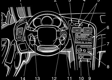
Checking headlight aims
The headlights have the beam angle gauges to check: 1 Vertical movement 2 Horizontal movement To obtain correct gauge readings, do these before you check the headlight aims. (cid:1) Make sure the body around the head-
light is not deformed.
(cid:1) Park the vehicle on a level spot. (cid:1) Fill up the fuel tank. (cid:1) Bounce the vehicle several times. A passenger should sit on the driver’s seat while checking the headlight aims.
176
Replacing light bulbs— The following illustrations show how to gain access to the bulbs. When replacing a bulb, make sure the ignition switch and light switch are off. Use bulbs with the wattage ratings given in the table.
CAUTION
Halogen bulbs have pressurized gas inside and require special han- dling. They can burst or shatter if scratched or dropped. Hold a bulb only by its plastic or metal case. Do not touch the glass part of a bulb with bare hands.
NOTICE
Only use a bulb of the listed type.
Vertical movement gauges: The bubble on the gauge should be within two marks from center on both sides.
Horizontal movement gauges: The triangle mark on the gauge should be within one mark from the “O” position. If a gauge reading is not within the accept- able range, have the aiming adjusted by your Toyota dealer.
Light bulbs
Headlights (low beam)
Headlights (high beam)
Front fog light
Parking and front turn sig- nal lights
W Type
Bulb No.
9006
55
9005
65
55
1157
27/8
Front side marker lights
194
3.8
Rear side marker, stop and tail lights (coupe)
1157
27/8
177
—Headlights
W Type
4.9
27
27/8
27
18
101.2
3.83.8
1. Unplug the connector while de- pressing the lock release. If the connector is tight, wiggle it.
2. Turn the bulb and remove it.
Bulb No. 194
1156
1157
1156
168
921
——
— — — —
—
Light bulbs
Rear side marker lights (liftback) Rear turn signal lights Stop and tail lights Back-up lights License plate lights High mounted stoplight Interior light (with moon roof)
Interior lights (without moon roof)
Personal lights Glovebox light Door courtesy lights Luggage compartment light Trunk light A: HB4 halogen bulbs B: HB3 halogen bulbs C: Single end bulbs D: Wedge base bulbs E: Double end bulbs
178
—Front fog lights
3. Install a new bulb and the connec- tor into the mounting hole. Aiming is not necessary after replacing the bulb. When aiming adjustment is nec- essary, contact your Toyota dealer.
1. Loosen the retainer screw and take out the beam unit.
2. Turn the cover counterclockwise and remove it.
179
3. Disconnect the cords.
4. Release the bulb retaining spring and remove the bulb. Install a new bulb and the bulb retaining spring. To install the bulb, align the cutouts of the bulb with the protrusions of the mounting hole.
5. Connect the cords, install the cover and turn it clockwise so that two triangle marks are aligned. Plug the connector together. Install the beam unit and tighten the screw.
180
—Parking and front turn signal lights
—Front side marker lights
Use a Phillips-head screwdriver.
Use a Phillips-head screwdriver.
181
—Rear side marker, rear turn signal, stop and tail, and back-up lights (coupe and convertible)
a: Rear turn signal light b: Rear side marker, stop and tail light c: Stop and tail light d: Back-up light
182
—Rear side marker, rear turn signal, stop and tail, and back-up lights (liftback)
—License plate lights
Use a Phillips-head screwdriver.
a: Rear side marker light b: Rear turn signal light c: Stop and tail light d: Back-up light
183
—High mounted stoplight (coupe)
—High mounted stoplight (liftback)
184
185
186
Part 8
SPECIFICATIONS(cid:1) Dimensions and weight (cid:1) Engine (cid:1) Fuel (cid:1) Service specifications (cid:1) Tires (cid:1) Fuses
187
Dimensions and weight
Overall length Overall width Overall height
Wheelbase Front tread Rear tread Vehicle capacity weight (occupants + luggage)
mm (in.) mm (in.) mm (in.)
mm (in.) mm (in.) mm (in.)
Coupe
Liftback
Convertible
*1
4495 (177.0) 1750 (68.9) 1295 (51.0) 1310 (51.6) *2
2538 (99.9) 1515 (59.6) 1495 (58.9)4425 (174.2) 1750 (68.9) 1290 (50.8) *1
1305 (51.4) *2
2538 (99.9) 1515 (59.6) 1495 (58.9)4495 (177.0) 1750 (68.9) 1310 (51.6) *1
1325 (52.2) *2
2538 (99.9) 1515 (59.6) 1495 (58.9)kg (lb.)
327
(725)
329
(725)
327
(725)
*1: Unladen vehicle plus two occupants *2: Unladen vehicle
188
Engine Model:
7A-FE and 5S-FE
Type:
4 cylinder in line, 4 cycle, gasoline
Bore and stroke, mm (in.):
7A-FE engine
81.0 x 85.5 (3.19 x 3.37)
5S-FE engine
87.0 x 91.0 (3.43 x 3.58)
Displacement, cm3 (cu. in):
7A-FE engine
1762 (107.5)
5S-FE engine
2164 (132.0)
Fuel Fuel type:
7A-FE engine—Unleaded gasoline, Research Octane Number 91 (Octane Rating 87) or higher 5S-FE engine—Unleaded gasoline, Research Octane Number 91 (Octane Rating 87) or higher. For improved ve- hicle performance, the use of premium unleaded gasoline with a Research Octane Number of 96 (Octane Rating 91) or higher is recommended.
Fuel tank capacity, L (gal., Imp. gal.):
60 (15.9, 13.2)
Service specifications ENGINE Valve clearance (engine cold), mm (in.)
7A-FE engine Intake 0.150.25 (0.0060.010) Exhaust 0.250.35 (0.0100.014) 5S-FE engine
0.190.29 (0.0070.011) Intake Exhaust 0.280.38 (0.0110.015)
Spark plug type: 7A-FE engine
NIPPONDENSO NGK
5S-FE engine
NIPPONDENSO NGK
Spark plug gap, mm (in.):
7A-FE engine 5S-FE engine
K16R-U BKR5EYA
PK20R11
BKR6EP110.8 (0.031) 1.1 (0.043)
189
Drive belt tension measured with Bor- oughs drive belt tension gauge No. BT-33-73F (used belt), Ibf:
7A-FE engine
Power steering pump belt
Air conditioning compressor belt
5S-FE engine
Generator belt 115 ± 20
80 ± 20
100 ± 20Generator belt 155 ± 20
95 ± 20
80 ± 20Vehicles with air conditioning
Vehicles without air conditioning
Power steering pump belt
ENGINE LUBRICATION Oil capacity (drain and refill), L (qt., Imp. qt.):
7A-FE engine With filter Without filter
5S-FE engine With filter Without filter
Oil grade:
3.7 (3.9, 3.3) 3.5 (3.7, 3.0)
3.9 (4.1, 3.4) 3.7 (3.9, 3.3)
API SH, “Energy-Conserving II” multi- grade engine oil or ILSAC multigrade engine oil is recommended.
Recommended oil viscosity (SAE): 5S-FE engine
Temperature range anticipated before next oil change 80040-L02U
7A-FE engine
Temperature range anticipated before next oil change 80040-L03U
COOLING SYSTEM Total capacity, L (qt., Imp.):
7A-FE engine
With manual transaxle 6.1 (6.4, 5.4) With automatic transaxle6.6 (7.0, 5.8)
5S-FE engine
With manual transaxle 6.7 (7.1, 5.9) With automatic transaxle7.1 (7.5, 6.2)
Coolant type:
With ethylene-glycol antifreeze (Do not use alcohol type.)
BATTERY —Maintenance type battery
Specific gravity reading at 20(cid:2)C (68(cid:2)F):
1.260
1.160
1.060Fully charged Half charged Discharged
—Non-maintenance battery
Open voltage* at 20(cid:2)C (68(cid:2)F): Fully charged Half charged Discharged
12.7 V 12.3 V 11.9 V
*: Voltage that is checked 20 minutes af- ter the key is removed with all the lights turned off
190
Charging rates:
Non-maintenance battery Maintenance type battery
Quick charge Slow charge
CLUTCH Pedal freeplay, mm (in.):
515 (0.20.6)
Fluid type:
MANUAL TRANSAXLE Oil capacity, L (qt., Imp. qt.): 7A-FE engine
1.9 (2.0, 1.7)
5S-FE engine
2.6 (2.7, 2.3)
Oil type:
SAE J1703 or FMVSS No. 116 DOT 3
Multipurpose gear oil API GL-4 or GL-5
Recommended oil viscosity:
SAE 75W-90
AUTOMATIC TRANSAXLE 7A-FE engine
Fluid capacity (drain and refill), L (qt., Imp. qt.):
Up to 3.1 (3.3, 2.7)
5 A max.
15 A max. 5 A max.
5S-FE engine
Automatic transmission
Fluid capacity (drain and refill), L (qt., Imp. qt.):
Up to 2.5 (2.6, 2.2)
Differential
Fluid capacity, L (qt., lmp. qt.):
1.6 (1.7, 1.4)
STEERING Wheel freeplay:
Less than 30 mm (1.2 in.)
Power steering fluid type:
Automatic transmission fluid DEXRON-II or -III
Fluid type:
Automatic transmission fluid DII or DEXRON-II
BRAKES Minimum pedal clearance when de- pressed, mm (in.):
7A-FE engine 5S-FE engine
75 (3.0) 80 (3.1)
Pedal freeplay, mm (in.):
16 (0.040.24)
Pad wear limit, mm (in.):
1.0 (0.04)
Lining wear limit, mm (in.):
1.0 (0.04)
Parking brake adjustment:
4-7 clicks
Fluid type:
SAE J1703 or FMVSS No. 116 DOT 3
191
Fuses
Front Rear
Tire pressure, kPa (kgf/cm2 or bar, psi): 185/70R14 88S and P185/70R14 87S 200 (2.0, 29) 200 (2.0, 29) 205/55R15 87V and P205/55R15 87V 230 (2.3, 33) 230 (2.3, 33) 420 (4.2, 60)
T125/70D16
Front Rear
Wheel size:
185/70R14 88S and P185/70R14 87S
14 x 6JJ
205/55R15 87V and P205/55R15 87V
15 x 6 1/2JJ 15 x 7JJ T125/70D16
16 x 4T
Wheel nut torque, N⋅m (kgf⋅m, ft⋅lbf):
103 (10.5, 76)
Engine compartment (left)-U.S.A.
Tires Tire size:
Spare tire
U.S.A.
T125/70D16
Canada
7A-FE engine
185/70R14 88S P185/70R14 87S 205/55R15 87V P205/55R15 87V
5S-FE engine
205/55R15 87V P205/55R15 87V
Except spare tire 7A-FE engine
185/70R14 88S P185/70R14 87S 205/55R15 87V P205/55R15 87V
5S-FE engine
205/55R15 87V P205/55R15 87V
192
Fuses (type A) 1 AM2 30 A: Starting system 2 HAZARD 10A: Emergency flashers 3 HORN 7.5 A: Horns 4 Radio NO.1 20 A: Car audio system 5 ECU-B 15 A: Anti-lock brake system, cruise control system 6 DOME 10 A: Interior lights, personal lights, luggage compartment light, trunk light, door courtesy lights, clock 7 HEAD (LH) 15 A: Left-hand headlight 8 HEAD (RH) 15 A: Right-hand head- light
9 SPARE: Spare fuse 10 SPARE: Spare fuse 11 SPARE: Spare fuse 12 ALT-S 7.5 A: Charging system 13 SRS WRN 7.5 A: SRS airbag warning light 14 EFI 15 A: Multiport fuel injection sys- tem/sequential multiport fuel injection system 15 HEAD (LH) LO 15 A: Left-hand head- light (low beam) 16 HEAD (RH) LO 15 A: Right-hand headlight (low beam) 17 HEAD-HI (RH) 15 A: Right-hand headlight (high beam)
193
Fuses (type B) 36 RDI 30 A: Electric cooling fan 37 CDS 30 A: Electric cooling fan 38 AM1 40 A: Electronic ignition system/ distributor ignition system 39 DOOR 30 A: Power door lock system, convertible top control system 40 DEF 30 A: Rear window defogger 41 POWER 30 A: Power windows, elec- tric moon roof Fuses (type C) 42 HTR 40 A: Air conditioning system 43 ALT 100 A: “ALT-S”, “TAIL”, “DOOR”, “DEF” and “POWER” fuses 44 MAIN 60 A: Starting system, head- lights, “HORN”, “DOME” and “RADIO” fuses 45 ABS 50 A: Anti-lock brake system
“HAZARD”,
“AM2”,
24 FOG 20 A: Front fog lights 25 CIG & RAD 15 A: Cigarette lighter, dig- ital clock display, car audio system 26 IGN 7.5 A: Charging system, dis- charge warning light, multiport fuel injec- tion system/sequential multiport fuel in- jection system, SRS airbag system 27 WIPER 20 A: Windshield wipers and washer, rear window wiper and washer 28 MIR-HTR 10 A: Multiport fuel injection system/sequential multiport fuel injection system 29 TURN 10 A: Turn signal lights, emer- gency flashers 30 TAIL 15 A: Tail lights, parking lights, front side marker lights, rear side marker lights, license plate lights 31 HTR 10 A: Air conditioning system, rear window defogger 32 GAUGE 10 A: Gauges and meters, power door lock system 33 ST 7.5 A: Starting system, multiport fuel injection system/sequential multiport fuel injection system 34 A/C 10 A: Air conditioning system 35 OBD II 7.5A: On-board diagnosis sys- tem
18 HEAD-HI (LH) 15 A: Left-hand headlight (high beam) 19 DRL 7.5 A: Daytime running light sys- tem 20 ECU-IG 15 A: Electronically con- trolled automatic transmission system, anti-lock brake system 21 SEAT-HTR 20 A: No circuit 22 PANEL 7.5 A: Instrument panel lights 23 STOP 15 A: Stop lights, high mounted stoplight, multiport fuel injection system/ sequential multiport fuel injection system, cruise control system cancel device, elec- tronically controlled automatic transmis- sion system, anti-lock brake system
194
Part 9
REPORTING SAFETY DEFECTS FOR U.S. OWNERS AND UNIFORM TIRE QUALITY GRADING(cid:1) Reporting safety defects for
U.S. owners
(cid:1) Uniform tire quality grading
inform
(NHTSA)
immediately
Reporting safety defects for U.S. owners If you believe that your vehicle has a defect which could cause a crash or could cause injury or death, you should the National Highway Traffic Safety Administration in addition to notifying Toyota Motor Sales, U.S.A., (Toll-free: 1-800-331-4331). similar If NHTSA it may open a complaints, investigation, and if it finds that a safety defect exists in a group of vehicles, it may order a recall and remedy campaign. However, NHTSA cannot become involved in individual problems between you, your dealer, or Toyota Motor Sales, U.S.A., Inc.
receives
Inc.
To contact NHTSA, you may either call the Auto Safety Hotline toll-free at 1-800-424-9393 (or 366-0123 in Washington D.C. area) or write to: NHTSA. U.S. Department of Transportation. Washington D.C. 20590. You can also obtain other information about motor vehicle safety from the Hotline.
195
Warning: The temperature grades for this tire are established for a tire that is proper- ly inflated and not overloaded. Excessive speed, underinflation, or excessive load- ing, wither separately or in combination, can cause heat buildup and possible tire failure.
Uniform tire quality grading This information has been prepared in ac- cordance with regulations issued by the National Highway Traffic Safety Adminis- tration of the U.S. Department of Trans- portation. It provides the purchasers and/ or prospective purchasers of Toyota vehicles with information on uniform tire quality grading. Your Toyota dealer will help answer any questions you may have as you read this information. DOT quality grades—All passenger vehicle tires must conform to Federal Safety Requirements in addition to these grades. These quality grades are molded on the sidewall. Treadwear—The treadwear grade is a comparative rating based on the wear rate of the tire when tested under con- trolled conditions on a specified govern- ment test course. For example, a tire graded 150 would wear one and a half (1-1/2) times as well on the government course as a tire graded 100. The relative performance of tires depends upon the actual conditions of their use, however, and may depart significantly from the norm due to variations in driving habits, service practices and differences in road characteristics and climate.
Traction A, B, C—The traction grades, from highest to lowest, are A, B, and C, and they represent the tire’s ability to stop on wet pavement as measured under controlled conditions on specified govern- ment test surfaces of asphalt and con- crete. A tire marked C may have poor trac- tion performance. Warning: The traction grade assigned to this tire is based on braking (straight ahead) traction tests and does not include cornering (turning) traction. Temperature A, B, C—The temperature grades are A (the highest), B, and C, rep- resenting the tire’s resistance to the gen- eration of heat and its ability to dissipate heat when tested under controlled condi- tions on a specific indoor laboratory test wheel. Sustained high temperature can cause the material of the tire to degener- ate and reduce tire life, and excessive temperature can lead to sudden tire fail- ure. The grade C corresponds to a level of performance which all passenger car tires must meet under the Federal Motor Ve- hicle Safety Standard No. 109. Grades B and A represent higher levels of perfor- mance on the laboratory test wheel than the minimum required by law.
196