- 2006 Subaru Legacy Owners Manuals
- Subaru Legacy Owners Manuals
- 2004 Subaru Legacy Owners Manuals
- Subaru Legacy Owners Manuals
- 2008 Subaru Legacy Owners Manuals
- Subaru Legacy Owners Manuals
- 2005 Subaru Legacy Owners Manuals
- Subaru Legacy Owners Manuals
- 2007 Subaru Legacy Owners Manuals
- Subaru Legacy Owners Manuals
- 2000 Subaru Legacy Owners Manuals
- Subaru Legacy Owners Manuals
- 2003 Subaru Legacy Owners Manuals
- Subaru Legacy Owners Manuals
- 2012 Subaru Legacy Owners Manuals
- Subaru Legacy Owners Manuals
- 2001 Subaru Legacy Owners Manuals
- Subaru Legacy Owners Manuals
- 2010 Subaru Legacy Owners Manuals
- Subaru Legacy Owners Manuals
- 2011 Subaru Legacy Owners Manuals
- Subaru Legacy Owners Manuals
- 2009 Subaru Legacy Owners Manuals
- Subaru Legacy Owners Manuals
- 2002 Subaru Legacy Owners Manuals
- Subaru Legacy Owners Manuals
- Download PDF Manual
-
If you have a flat tire while driving, never brake suddenly; keep driving straight ahead while gradually reducing speed. Then slowly pull off the road to a safe place.
1. Park on a hard, level surface, whenever possible, then stop the en- gine. 2. Set the parking brake securely and shift a manual transmission ve- hicle in reverse or an automatic transmission vehicle in the “P” (Park) position. 3. Turn on the hazard warning flasher and have everyone get out of the vehicle. 4. Put wheel blocks at the front and rear of the tire diagonally opposite the flat tire.
HGS038BA
– CONTINUED –
9-5
5. Take out the spare tire, jack, and wheel nut wrench.
Jack
Jack handle
Spare tire
HBF015CB
HB8004BD
Temporary spare tire
HB9003BB
HB6008BC
HS0252
The spare tire is stored under the floor of the trunk or cargo area. To remove the spare tire, proceed as follows: Sedan: Remove the floor cover from the trunk. Remove the storage tray. Turn the attaching bolt counterclockwise, then take the spare tire out. Station wagon: Open the lid and hang the hook provided on the under-
9-6
In case of emergency
side of the lid on the rear edge of the roof to keep the lid open. Remove the storage tray. Turn the attaching bolt counterclockwise, then take spare tire out.
If the spare tire provided in your vehicle is a temporary spare tire, care- fully read the section “Temporary spare tire” in this chapter and strictly follow the instructions.
HB9001BB
HB7008CD
The jack is stored on the left side of the trunk or cargo area.
To take out the jack: Remove the cover, turn the jackscrew counterclockwise to loosen it, then remove the jack.
HB9040BA
HB9041BA
If the jackscrew is too tight to be loosened by hand, loosen it using a screwdriver or the jack handle.
– CONTINUED –
9-7
The jack handle is stored under the spare tire cover.
NOTE Make sure the jack is well lubricated before using it.
6. (If your vehicle has wheel covers) Insert the wheel nut wrench into the notch provided in the wheel cover, and pry it off.
HB9032BA
OM-H0376
7. Loosen the wheel nuts using the wheel nut wrench but do not remove the nuts. 8. Place the jack under the side sill at the front or rear jack-up point clos- est to the flat tire.
OM-H2262
HB9012BB
Turn the jackscrew by hand until the jack head engages firmly into the jack-up point. If your vehicle is equipped with side sill skirts, jack-up points are pointed
9-8
to by arrow marks on the underside of the side sill skirt. Place the jack under the front or rear jack-up point closest to flat tire.
In case of emergency
HS9023BA
9. Insert the jack handle into the jackscrew, and turn the handle until the tire clears the ground. Do not raise the vehicle higher than necessary.
OM-H2263
10. Remove the wheel nuts and the flat tire. 11. Before putting the spare tire on, clean the mounting surface of the wheel and hub with a cloth.
– CONTINUED –
9-9
OM-H0172
HG0104
12. Put on the spare tire. Replace the wheel nuts. Tighten them by hand. 13. Turn the jack handle counterclockwise to lower the vehicle. 14. Use the wheel nut wrench to securely tighten the wheel nuts to the specified torque, following the tightening order in the illustration.
OM-H0377
The torque for tightening the nuts is 58 to 72 ft-lb (78 to 98 N-m, 8 to 10
kg-m). This torque is equivalent to applying about 88 to 110 lbs (40 to 50
kg) at the top of the wheel nut wrench. Never use your foot on the wheel nut wrench or a pipe extension on the wrench because you may exceed the specified torque. Have the wheel nut torque checked at the nearest automotive service facility.15. Store the flat tire in the spare tire compartment.
9-10
In case of emergency
Flat tire
Attaching bolt
Spacer
HS0153
When storing a conventional tire, put the spacer upside down and tight- en the attaching bolt firmly. Also store the jack and wheel nut wrench in their storage locations.
HB9040CA
HB9041CA
After placing the jack in its storage location, turn the jackscrew clock- wise by hand until it becomes too hard to turn. Then, tighten it by an additional 1/4 – 1/3 of a turn using a screwdriver or the jack handle. Un- less the jack is properly secured, it may rattle while the vehicle is mov- ing.
– CONTINUED –
9-11
Jump starting
WARNING
D Battery fluid is SULFURIC ACID. Do not let it come in contact with the eyes, skin, clothing or the vehicle. If battery fluid gets on you, thoroughly flush the exposed area with water immediately. Get medical help if the fluid has entered your eyes. If battery fluid is accidentally swallowed, immediately drink a large amount of milk or water, and obtain immediate medical help. Keep everyone including children away from the battery. D The gas generated by a battery explodes if a flame or spark is brought near it. Do not smoke or light a match while jump start- ing. D Never attempt jump starting if the discharged battery is frozen. It could cause the battery to burst or explode. D Whenever working on or around a battery, always wear suit- able eye protectors, and remove metal objects such as rings, bands or other metal jewelry. D Be sure the jumper cables and clamps on them do not have loose or missing insulation. Do not jump start unless cables in suitable condition are avail- able. D A running engine can be dangerous. Keep your fingers, hands, clothing, hair and tools away from the cooling fan, belts and any other moving engine parts. Removing rings, watches and ties is advisable.
When your vehicle does not start due to a run down (discharged) bat- tery, the vehicle may be jump started by connecting your battery to another battery (called the booster battery) with jumper cables.
Jump starting is dangerous if it done incorrectly. If you are unsure about the proper procedure for jump starting, consult a competent mechanic.
9-12
In case of emergency
B How to jump start 1. Make sure the booster battery is 12 volts and the negative terminal is grounded. 2. If the booster battery is in another vehicle, do not let the two ve- hicles touch. 3. Turn off all unnecessary lights and accessories. 4. Connect the jumper cables exactly in the sequence illustrated.
HB8007BC
– CONTINUED –
9-13
HB9031BB
1 Connect one jumper cable to the positive (+) terminal on the discharged battery. 2 Connect the other end of the jumper cable to the positive (+) terminal of the booster battery. 3 Connect one end of the other cable to the negative (–) terminal of the booster battery. 4 Connect the other end of the cable.
2.5 liter models: To the engine lifting bracket. 3.0 liter models: To the strut mounting nut.
Make sure that the cables are not near any moving parts and that the cable clamps are not in contact with any other metal.
5. Start the engine of the vehicle with the booster battery and run it at moderate speed. Then start the engine of the vehicle that has the dis- charged battery. 6. When finished, carefully disconnect the cables in exactly the re- verse order.
9-14
Engine overheating
In case of emergency
WARNING
Never attempt to remove the radiator cap until the engine has been shut off and has fully cooled down. When the engine is hot, the coolant is under pressure. Removing the cap while the engine is still hot could release a spray of boiling hot coolant, which could burn you very seriously.
If the engine overheats, safely pull off the road and stop the vehicle in a safe place.
B If steam is coming from the engine compartment Turn the engine off and get everyone away from the vehicle until it cools down.
B If no steam is coming from the engine compartment 1. Keep the engine running at idling speed. 2. Open the hood to ventilate the engine compartment. Confirm that the cooling fan is turning. If the fan is not turning, im- mediately turn the engine off and contact your authorized dealer for repair. 3. After the engine coolant temperature has dropped, turn off the en- gine. If the temperature gauge stays at the overheated zone, turn the en- gine off. 4. After the engine has fully cooled down, check the coolant level in the reserve tank. If the coolant level is below the “MIN” mark, add coolant up to the “MAX” mark. 5. If there is no coolant in the reserve tank, add coolant to the reserve tank. Then remove the radiator cap and fill the radiator with coolant.
If you remove the radiator cap from a hot radiator, first wrap a thick cloth around the radiator cap, then turn the cap counterclockwise slowly without pressing down until it stops. Release the pressure from
– CONTINUED –
9-15
the radiator. After the pressure has been fully released, remove the cap by pressing down and turning it.
Towing
WARNING
Never tow AWD vehicles (both AT and MT) with the front wheels raised off the ground while the rear wheels are on the ground, or with the rear wheels raised off the ground while the front wheels are on the ground. This will cause the vehicle to spin away due to the operation or deterioration of the center differential.
HG9013BA
If towing is necessary, it is best done by your SUBARU dealer or a com- mercial towing service. Observe the following procedures for safety.
B Towing and tie-down hooks
CAUTION
D Use only specified towing hooks and tie-down hooks. Never use suspension parts or other body parts for towing or tie-down purposes. D Never use the tie-down hook closest to the muffler under the vehicle for towing purposes. D Do not apply excessive lateral load to the towing hooks.
9-16
In case of emergency
HB9048BB
HB9051BB
Towing and tie-down hook HB8012BB
HB8013BB
– CONTINUED –
9-17
HB9010BB
The towing hooks should be used only in an emergency (e.g., to free a stuck vehicle from mud, sand or snow).
The front towing hook is located on the inside of the towing hook cov- er below the right-hand headlight.
n Towing hook cover removal procedure
For except OUTBACK models:
HB9049BA
To use the towing hook, insert the top end of the flat tip screwdriver in a slot on the upper part of the cover, and remove the cover while pry- ing it off. Remove the towing hook cover by pulling it toward the side of the ve- hicle and toward you.
9-18
For OUTBACK models:
In case of emergency
HB9045BB
HB9042BA
1. Squeeze the sides of portion A and pull the towing hook cover to- ward you.
HB9021CB
HB9043BA
2. Press portion B and simultaneously pull the towing hook cover to- ward you.
– CONTINUED –
9-19
HB9044AA
3. Turn the towing hook cover clockwise, pivoting it about the side that is next to the fog lamp. Pull out the towing hook cover to remove it.
n Towing hook cover installation procedure
For except OUTBACK models:
HB9052BA
Align the towing hook cover with its original installation position and press all parts of it into place.
9-20
For OUTBACK models:
In case of emergency
1. IInsert the projection C into the hole D.
HB9044CB
2. Push at the portion E.
HB9030CB
– CONTINUED –
9-21
B Using a flat-bed truck
HB8008AA
This is the best way to transport your vehicle. Use the following proce- dures to ensure safe transportation. 1. Shift the selector lever into the “P” position for automatic transmis- sion vehicles or “1st” for manual transmission vehicles. 2. Pull up the parking brake lever firmly. 3. Secure the vehicle onto the carrier properly with safety chains. Each safety chain should be equally tightened and care must be tak- en not to pull the chains so tightly that the suspension bottoms out.
B Towing with all wheels on the ground
WARNING
D Never turn the ignition switch to the “LOCK” position while the vehicle is being towed because the steering wheel and the direc- tion of the wheels will be locked. D Remember that the brake booster and power steering do not function when the engine is not running. Because the engine is turned off, it will take greater effort to operate the brake pedal and steering wheel.
9-22
In case of emergency
CAUTION
D If transmission failure occurs, transport your vehicle on a flat- bed truck. D Do not run the engine while being towed in this method. Trans- mission damage could result if the vehicle is towed with the engine running. D For vehicles with automatic transmission, the traveling speed must be limited to less than 20 mph (30 km/h) and the traveling distance to less than 31 miles (50 km). For greater speeds and distances, transport your vehicle on a flat-bed truck.
HB8010AA
1. Check the transmission and differential oil levels and add oil to bring it to the upper level if necessary. 2. Release the parking brake and put the transmission in neutral. 3. The ignition switch should be in the “ACC” position while the ve- hicle is being towed. 4. Take up slack in the towline slowly to prevent damage to the ve- hicle.
– CONTINUED –
9-23
Moonroof — if the moonroof cannot be closed
If the moonroof cannot be closed with the moonroof switch, you can close the moonroof manually.
B Sedan 1. Take out the hex-headed wrench from the glove box and screw- driver from the tool bag.
HB9006BA
HB9007BB
2. Remove the map light lens by prying the edge of the lens with a regular screwdriver, then remove the switch body retaining screws and take off the moonroof switch.
HB9008BA
3. Insert the wrench in the end of the motor shaft. D To lower the moonroof, turn the wrench clockwise. D To close the moonroof, turn the wrench counterclockwise. Have your vehicle checked by an authorized SUBARU dealer.
9-24
In case of emergency
B Station wagon 1. Take out the hex-headed wrench from the glove box and screw- driver from the tool bag.
HB9033BA
HB9034BB
2. Remove the plug on the roof trim by inserting the end of the regular screwdriver between the roof and plug and prying it off. 3. Insert the wrench in the end of the motor shaft. To close the moonroof, turn the wrench clockwise.
Have your vehicle checked or repaired by an authorized SUBARU dealer.
Maintenance tools
Your vehicle is equipped with the following maintenance tools:
HB9011AA
– CONTINUED –
9-25
Screwdriver Wheel nut wrench Hex-headed wrench (for vehicles with moonroof)
J Jack and jack handle
Jack
Jack handle
Spare tire
HBF015CB
HB9001BA
HB8004BD
HB7008CA
The jack is stored on the left side of the trunk or cargo area.
To take out the jack, turn the jackscrew counterclockwise to loosen it, then remove the jack.
The jack handle is stored under the spare tire cover.
For how to use the jack, refer to “Flat tires”.
9-26
Appearance care
Exterior care
Washing Waxing and polishing Cleaning aluminum wheels Cleaning fog light lens (for OUTBACK)
. . . . . . . . . . . . . . . . . . . . . . . . . . . . . . . . . . . . . . . . . . . . . . . . . . . . . . . . . . . . . . . . . . . . . . . . . . . . . . . . . . . . . . . . . . . . . . . . . . . . . . . . . . . . . . . . . . . . . . . . . . . . . . . . . . . . . . . . . . . . . . . . . . . . . . . . . . . . . . . . . . . . . . . . . . . . . . . . . . . . . . . . . . . . . . . . . . . . . . . . . . . . . . . . . . . . . . . . . . . . . . . . . . . . . . . . . . . . . . . . . . . . . . . . . . . . . . .
Corrosion protection Cleaning the interior
. . . . . . . . . . . . . . . . . . . . . . . . . . . . . . . . . . . . . . . . . . . . . . . . . . . .
. . . . . . . . . . . . . . . . . . . . . . . . . . . . . . . . . . . . . . . . . . . . . . . . . . . . .
10-2
10-2
10-3
10-4
10-4
10-5
10-610
Exterior care
J Washing
CAUTION
D When washing the vehicle, the brakes may get wet. As a result, the brake stopping distance will be longer. To dry the brakes, drive the vehicle at a safe speed while lightly pressing the brake pedal to heat up the brakes. D Do not wash the engine compartment and areas adjacent to it. If water enters the engine air intake, electrical parts or the power steering fluid reservoir, it will cause engine trouble or faulty power steering respectively.
The best way to preserve your vehicle’s beauty is frequent washing. Wash the vehicle at least once a month to avoid contamination by road grime.
Wash dirt off with a wet sponge and plenty of lukewarm or cold water. Do not wash the vehicle with hot water and in direct sunlight.
Salt, chemicals, insects, tar, soot and bird droppings should be washed off by using a light detergent, as required. If you use a light detergent, make certain that it is a neutral detergent. Do not use strong soap or chemical detergents. All cleaning agents should be promptly flushed from the surface and not allowed to dry there. Rinse the vehicle thor- oughly with plenty of lukewarm water. Wipe the remaining water off with a chamois or soft cloth.
NOTE When having your vehicle washed in an automatic car wash, make sure beforehand that the car wash is of suitable type. If the vehicle is equipped with a rear/roof spoiler, it may be damaged by car wash brushes or other equipment.
10-2
Appearance care
B Washing the underbody Chemicals, salts and gravel used for deicing road surfaces are ex- tremely corrosive, accelerating the corrosion of underbody compo- nents, such as the exhaust system, fuel and brake lines, brake cables, floor pan and fenders, and suspension. Thoroughly flush the underbody and inside of the fenders with luke- warm or cold water at frequent intervals to reduce the harmful effects of such agents.
B Using a warm water washer D Keep a good distance of 12 in (30 cm) or more between the wash- er nozzle and the vehicle. D Do not wash the same area continuously. D If a stain will not come out easily, wash by hand. Some warm water washers are of the high temperature, high pressure type, and they can damage or deform the resin parts such as mouldings, or cause water to leak into the vehicle.
J Waxing and polishing Always wash and dry the vehicle before waxing and polishing. Use a good quality polish and wax and apply them according to the manufacturer’s instructions. Wax or polish when the painted surface is cool.
Be sure to polish and wax the chrome trim, as well as the painted sur- faces. Loss of wax on a painted surface leads to loss of the original lus- ter and also quickens the deterioration of the surface. It is recommended that a coat of wax be applied at least once a month, or whenever the surface no longer repels water.
If the appearance of the paint has diminished to the point where the lus- ter or tone cannot be restored, lightly polish the surface with a fine- grained compound. Never polish just the affected area, but include the surrounding area as well. Always polish in only one direction. A No. 2000
grain compound is recommended. Never use a coarse-grained com- pound. Coarser grained compounds have a smaller grain-size number and could damage the paint. After polishing with a compound, coat with– CONTINUED –
10-3
10
wax to restore the original luster. Frequent polishing with a compound or an incorrect polishing technique will result in removing the paint layer and exposing the undercoat. When in doubt, it is always best to contact your SUBARU dealer or an auto paint specialist.
J Cleaning aluminum wheels D Promptly wipe the aluminum wheels clean of any kind of grime or agent. If dirt is left on too long, it may be difficult to clean off. D Do not use soap containing grit to clean the wheels. Be sure to use a neutral cleaning agent, and later rinse thoroughly with water. Do not clean the wheels with a stiff brush or expose them to a high-speed wash- ing device. D Clean the vehicle (including the aluminum wheels) with water as soon as possible when it has been splashed with sea water, exposed to sea breezes, or driven on roads treated with salt or other agents.
J Cleaning fog light lens (for OUTBACK)
HBA017BB
1. Stop the vehicle in a safe place. 2. Stop the engine and turn off the fog lights. 3. Check that the fog lights are not hot. Then, grasp the protector and turn it approximately 10° counter-clockwise. 4. Pull the protector off the fog light. 5. Wash the lens with water. 6. Apply the protector to the lens at an angle of approximately 10° from
10-4
Appearance care
the fog light’s horizontal center line. Then, turn the protector clockwise until it stops. Finally, check that the protector’s horizontal bars are parallel with the fog light’s horizontal center line.
Corrosion protection
Your SUBARU has been designed and built to resist corrosion. Special materials and protective finishes have been used on most parts of the vehicle to help maintain fine appearance, strength, and reliable opera- tion.
B Most common causes of corrosion The most common causes of corrosion are: 1. The accumulation of moisture retaining dirt and debris in body panel sections, cavities, and other areas. 2. Damage to paint and other protective coatings caused by gravel and stone chips or minor accidents.
Corrosion is accelerated on the vehicle when: 1. It is exposed to road salt or dust control chemicals, or used in coastal areas where there is more salt in the air, or in areas where there is considerable industrial pollution. 2. It is driven in areas of high humidity, especially when temperatures range just above freezing. 3. Dampness in certain parts of the vehicle remains for a long time, even though other parts of the vehicle may be dry. 4. High temperatures will cause corrosion to parts of the vehicle which cannot dry quickly due to lack of proper ventilation.
B To help prevent corrosion Wash the vehicle frequently. If you drive on salted roads in the winter or if you live in a coastal area, you should flush the underbody with fresh water frequently.
After the winter has ended, it is recommended that the underbody be given a very thorough washing.
– CONTINUED –
10-5
10
Before the beginning of winter, check the condition of underbody components, such as the exhaust system, fuel and brake lines, brake cables, suspension, steering system, floor pan, and fenders. If any of them are found to be rusted, they should be given an appropriate rust prevention treatment or should be replaced. Contact your SUBARU dealer to perform this kind of maintenance and treatment if you need assistance.
Repair chips and scratches in the paint as soon as you find them.
Check the interior of the vehicle for water and dirt accumulation under the floor mats because that could cause corrosion. Occasionally check under the mats to make sure the area is dry.
Keep your garage dry. Do not park your vehicle in a damp, poorly ventilated garage. In such a garage, corrosion can be caused by dampness. If you wash the vehicle in the garage or put the vehicle into the garage when wet or covered with snow, that can cause dampness.
If your vehicle is operated in cold weather and/or in areas where road salts and other corrosive materials are used, the door hinges and locks, trunk lid lock, and hood latch should be inspected and lubri- cated periodically.
Cleaning the interior
Use a vacuum cleaner to get rid of the dust and dirt. Wipe the vinyl areas with a clean, damp cloth.
B Seat fabric Remove loose dirt, dust or debris with a vacuum cleaner. If the dirt is caked on the fabric or hard to remove with a vacuum cleaner, use a soft blush then vacuum it. Wipe the fabric surface with a tightly wrung cloth and dry the seat fabric thoroughly. If the fabric is still dirty, wipe using a solution of mild soap and lukewarm water then dry thoroughly.
If the stain does not come out, try a commercially-available fabric
10-6
Appearance care
cleaner. Use the cleaner on a hidden place and make sure it does not affect the fabric adversely. Use the cleaner according to its instruc- tions.
B Leather seat materials The leather used by SUBARU is a high quality natural product which will retain its distinctive appearance and feel for many years with proper care. Allowing dust or road dirt to build up on the surface can cause the material to become brittle and to wear prematurely. Regular cleaning with a soft, moist, natural fiber cloth should be performed monthly, taking care not to soak the leather or allow water to penetrate the stitched seams. A mild detergent suitable for cleaning woolen fabrics may be used to remove difficult dirt spots, rubbing with a soft, dry cloth afterwards to restore the luster. If your SUBARU is to be parked for a long time in bright sunlight, it is recommended that the seats and headrests be covered, or the windows shaded, to prevent fading or shrinkage. Minor surface blemishes or bald patches may be treated with a com- mercial leather spray lacquer. You will discover that each leather seat section will develop soft folds or wrinkles, which is characteristic of genuine leather.
B Synthetic leather upholstery The synthetic leather material used on the SUBARU may be cleaned using mild soap or detergent and water, after first vacuuming or brushing away loose dirt. Allow the soap to soak in for a few minutes and wipe off with a clean, damp cloth. Commercial foam-type clean- ers suitable for synthetic leather materials may be used when neces- sary.
NOTE Strong cleaning agents such as solvents, paint thinners, window cleaner or gasoline must never be used on leather or synthetic interior materials.
– CONTINUED –
10-7
10
10-8
Maintenance and service
. . . . . . . . . . . . . . . . . . . . . . . . . . . . . . . . . . . . . . . . . . . . . . . . . .
. . . . . . . . . . . . . . . . . . . . . . . . . . . . . . . . . . . . . . . . . . . . . .
Maintenance schedule Maintenance precautions Engine hood Engine compartment overview Engine oil Cooling system Engine coolant
. . . . . . . . . . . . . . . . . . . . . . . . . . . . . . . . . . . . . . . . . . . . . . . . . . . . . . . . . . . . . . . .
. . . . . . . . . . . . . . . . . . . . . . . . . . . . . . . . . . . . . . .
. . . . . . . . . . . . . . . . . . . . . . . . . . . . . . . . . . . . . . . . . . . . . . . . . . . . . . . . . . . . . . . . . . . .
. . . . . . . . . . . . . . . . . . . . . . . . . . . . . . . . . . . . . . . . . . . . . . . . . . . . . . . . . . . . . . . . . . . . . . . . . . . . . . . . . . . . . . . . . . . . . . . . . . . . . . . . . . . . . . . . . . . . . . .
. . . . . . . . . . . . . . . . . . . . . . . . . . . . . . . . . . . . . . . . . . . . . . . . . . . . . .
. . . . . . . . . . . . . . . . . . . . . . . . . . . . . . . . . . . . . . . . . . . . . . . . . . . . . . . . . . . . . . . . .
. . . . . . . . . . . . . . . . . . . . . . . . . . . . . . . . . . . . . . . . . . . . . . . . . . . . . . . . . . . . . . . . . . .
. . . . . . . . . . . . . . . . . . . . . . . . . . . . . . . . . . . . . . . . . . . . . . . .
. . . . . . . . . . . . . . . . . . . . . . . . . . . . . . . . . . . . . . . . .
. . . . . . . . . . . . . . . . . . . . . . . . . . . .
. . . . . . . . . . . . . . . . . . . . . . . . . . . . . . . . . . . . . . . . . . . . . . . .
. . . . . . . . . . . . . . . . . . . . . . . . . . . . . . . . . . . . . . . . . . . . . . . . . . . . .
Air cleaner element Spark plugs Drive belts Manual transmission oil Automatic transmission fluid Front differential gear oil (AT vehicles) Rear differential gear oil Power steering fluid Brake fluid Clutch fluid (MT vehicles) Brake booster Brake pedal Clutch pedal (Manual transmission vehicles) Replacement of brake pad and lining Parking brake stroke Tires and wheels
. . . . . . . . . . . . . . . . . . . . . . . . . . . . . . . . . . . . . . . . . . . . . . . . . . . . . . . . . . . . . . . . . . .
. . . . . . . . . . . . . . . . . . . . . . . . . . . . . . . . . . . . . . . . . . . . . .
. . . . . . . . . . . . . . . . . . . . . . . . . . . . . . . . . . . . . . . . . . . . . . . . . . . . . . . . . . . . . .
. . . . . . . . . . . . . . . . . . . . . . . . . . . . . . . . . . . . . . . . . . . . . . . . . . . . . . . . . . . . . . . . .
. . . . . . . . . . . . . . . . . . . . . . . . . . . . . . . . . . . . . . . . . . . . . . . . . . . .
Types of tires Tire inspection Tire pressures and wear Wheel balance Wear indicators Tire rotation Tire replacement Wheel replacement Wheel covers
. . . . . . . . . . . . . . . . . . . . . . . . . . . . . . . . . . . . . . . . . . . . . . . . . . . . . . . . . . . . . . . . . . . . . . . . . . . . . . . . . . . . . . . . . . . . . . . . . . . . . . . . . . . . . . . . . . . . . . . . . . . . . . . . . . . . . . . . . . . . . . . . . . . . . . . . . . . . . . . . . . . . . . . . . . . . . . . . . . . . . . . . . . . . . . . . . . . . . . . . . . . . . . . . . . . . . . . . . . . . . . . . . . . . . . . . . . . . . . . . . . . . . . . . . . . . . . . . . . . . . . . . . . . . . . . . . . . . . . . . . . . . . . . . . . . . . . . . . . . . . . . . . . . . . . . . . . . . . . . . . . . . . . . . . . . . . . . . . . . . . . . . . . . . . . . . . . . . . . . . . . . . . . . . . . . . . . . . . . . . . . . . . . . . . . . . . . . . . . . . . . . . . . . . . . . . . . . . . . . . . . . . . . . . . . . . . . . . . . . . . . . . . . . . . . . . . . . . . . . . . . . . . . . . . . . . . . . . . . . . . . . . . . . . . . . . . . . . . . . . . . . . . . . . . . . . . . . . . . . . . . . . . . . . . . . . . . . . . . . . . . . . . . . . . . . . . . . . . . . . . . . . . . . . . . . . . . . . . . .
Aluminum wheels (if equipped) Windshield washer fluid Replacement of windshield wiper blades
. . . . . . . . . . . . . . . . . . . . . . . . . . . . . . . . . . . . . .
. . . . . . . . . . . . . . . . . . . . . . . . . . . . . . . . . . . . . . . . . . . . . . . .
. . . . . . . . . . . . . . . . . . . . . . . .
. . . . . . . . . . . . . . . . . . .
. . . . . . . . . . . . . . . . . . . . . . . . . . . . . .
11-3
11-3
11-5
11-7
11-9
11-14
11-15
11-18
11-21
11-22
11-23
11-24
11-26
11-27
11-29
11-30
11-32
11-33
11-34
11-35
11-36
11-37
11-38
11-38
11-39
11-39
11-42
11-43
11-44
11-44
11-45
11-46
11-47
11-47
11-4811
. . . . . . . . . . . . . . . . . . . . . . . . . . . . . . . . . . . . . . . . . . . . . . . . . . . . . . . . . . . . . . . . . . . . . . . .
. . . . . . . . . . . . . . . . . . . . . . . . . . . . . . . . . . . . . . . . . . . . . . . . . . . . . . . . . . . . . . . . . . . . . . . . .
. . . . . . . . . . . . . . . . . . . . . . . . . . . . . . . . . . . . . . . . . . . . . . . . . . . . . . . . . . . . . . . . . . . .
Battery Fuses Main fuse Installation of accessories Replacing bulbs
. . . . . . . . . . . . . . . . . . . . . . . . . . . . . . . . . . . . . . . . . . . . .
. . . . . . . . . . . . . . . . . . . . . . . . . . . . . . . . . . . . . . . . . . . . . . . . . . . . . . . . . . . . . . . . . . . . . . . . . . . . . . . . . . . . . . . . . . . . . . . . . . . . . . . . . . . . . . . . . . . . . . . . . . . . . . . . . . . . . . . . . . . . . . . . . . . . . . . . . . . . . . . . . . . . . . . . . . . . . . . . . . . . . . . . . . . . . . . . . . . . . . . . . . . . . . . . . . . . . . . . . . . . . . . . . . . . . . . . . . . . . . . . . . . . . . . . . . . . . . . . . . . . . . . . . . . . . . . . . . . . . . . . . . .
Headlight Front fog light (if equipped) Front turn signal light, parking light and marker light Rear combination lights License plate light Map light, dome light, luggage compartment light
and door step light
Trunk light High mount stop light
. . . . . . . . . . . . . . . . . . . . . . . . . . . . . . . . . . . . . . . . . . . . . . . . . . . . . . . . . . . . . . . . . . . . . . . . . . . . . . . . . . . . . . . . . . . . . . . . . . . . . . . . . . . . . . . . . . . . . . . . . . . . . . . . . . . . . . . . . . . . . . . . . . . . . . . . . . . . . . . . . . . . . . .
11-51
11-52
11-54
11-54
11-55
11-57
11-59
11-59
11-61
11-6411-65
11-66
11-6711-2
Maintenance and service
Maintenance schedule
The scheduled maintenance items required to be serviced at regular in- tervals are shown in the “Warranty and Maintenance Booklet”.
For details of your maintenance schedule, read the separate “Warranty and Maintenance Booklet”.
Maintenance precautions
When maintenance and service are required, it is recommended that all work be done by an authorized SUBARU dealer.
If you perform maintenance and service by yourself, you should familiar- ize yourself with the information provided in this section on general main- tenance and service for your SUBARU.
Incorrect or incomplete service could cause improper or unsafe vehicle operation. Any problems caused by improper maintenance and service performed by you are not eligible for warranty coverage.
WARNING
D Testing of an All-Wheel Drive vehicle must NEVER be per- formed on a single two-wheel dynamometer or similar apparatus. Attempting to do so will result in transmission damage and in uncontrolled vehicle movement and may cause an accident or injuries to persons nearby. D Always select a safe area when performing maintenance on your vehicle. D Always be very careful to avoid injury when working on the ve- hicle. Remember that some of the materials in the vehicle may be hazardous if improperly used or handled, for example, battery acid. D Your vehicle should only be serviced by persons fully compe- tent to do so. Serious personal injury may result to persons not experienced in servicing vehicles.
– CONTINUED –
11-3
11
D Always use the proper tools and make certain that they are well maintained. D Never get under the vehicle supported only by a jack. Always use a safety stands to support the vehicle. D Never keep the engine running in a poorly ventilated area, such as a garage or other closed areas. D Do not smoke or allow open flames around the fuel or battery. This will cause a fire. D Because the fuel system is under pressure, replacement of the fuel filter should be performed only by your SUBARU dealer. D Wear adequate eye protection to guard against getting oil or fluids in your eyes. If something does get in your eyes, thorough- ly wash them out with clean water. D Do not tamper with the wiring of the SRS airbag system or seatbelt pretensioner system, or attempt to take its connectors apart, as that may activate the system or it can render it inopera- tive. The wiring and connectors of these systems are yellow for easy identification. NEVER use a circuit tester for these wiring. If your SRS airbag or seatbelt pretensioner needs service, con- sult your nearest SUBARU dealer.
J Before checking or servicing in the engine compart-
ment
D Always stop the engine and set the parking brake firmly to pre- vent the vehicle from moving. D Always let the engine cool down. Engine parts become very hot when the engine is running and remain hot for some time af- ter the engine is stopped. D Do not spill engine oil, engine coolant, brake fluid or any other fluid on hot engine components. This may cause a fire. D Always remove the key from the ignition switch. When the ignition switch is in the “ON” position, the cooling fan may oper- ate suddenly even when the engine is stopped.
11-4
Maintenance and service
J When you do checking or servicing in the engine
compartment while the engine is running
A running engine can be dangerous. Keep your fingers, hands, clothing, hair and tools away from the cooling fan, belts and any other moving engine parts. Removing rings, watches and ties is advisable.
Engine hood
WARNING
Always check that the hood is properly locked before you start driving. If it is not, it might fly open while the vehicle is moving and block your view, which may cause an accident and serious bodily injury.
HBB001BA
HBB002BA
11
– CONTINUED –
11-5
HBB003BA
To open the hood: 1. Pull the hood release knob under the instrument panel. 2. Release the secondary hood release located under the front grille by moving the lever toward the left. Lift up the hood, release the hood prop from its retainer and put the end of the hood prop into the slot in the hood.
To close the hood: 1. Lift the hood slightly and remove the hood prop from the slot in the hood and return the prop to its retainer. 2. Lower the hood until it approaches about 6 in. (15 cm) from the closed position and let it drop. 3. After closing the hood, be sure the hood is securely locked.
If this does not close the hood, release it from a slightly higher position. Do not push the hood forcibly to close it. It could deform the metal.
11-6
Maintenance and service
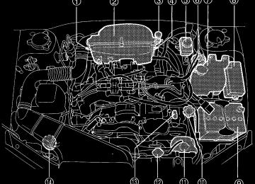
Engine compartment overview
B 2.5 liter models
1 Manual transmission oil level gauge (MT) (page 11-23) or Differential gear oil level gauge (AT) (page 11-26)
2 Air cleaner element
(page 11-18)
3 Clutch fluid reservoir
(page 11-32)
4 Automatic
transmission level gauge (page 11-24)
5 Brake fluid reservoir
(page 11-30)
6 Fuel filter
HBB036BB
7 Windshield washer tank
(page 11-47)
8 Fuse box (page 11-52) 9 Battery (page 11-51) Q Engine oil filler cap
(page 11-9)
W Engine coolant reservoir
(page 11-15)
11
fluid
E Radiator cap (page 11-15) R Engine oil level gauge
(page 11-9)
T Power steering fluid reservoir
(page 11-29)
– CONTINUED –
11-7
B 3.0 liter models
1 Air cleaner element
(page 11-18)
2 Differential gear oil level gauge
(AT) (page 11-26)
3 Automatic
transmission level gauge (page 11-24)
4 Brake fluid reservoir
(page 11-30)
5 Fuel filter 6 Windshield washer tank
(page 11-47)
11-8
HBB058BB
7 Fuse box (page 11-52) 8 Battery (page 11-51) 9 Engine oil filler cap
(page 11-9)
fluid
Q Engine coolant reservoir
(page 11-15)
W Engine oil level gauge
(page 11-9)
E Radiator cap (page 11-15) R Power steering fluid reservoir
(page 11-29)
Maintenance and service
Engine oil
B Checking the oil level Check the engine oil level at each fuel stop.
HBB004JA
HBB061BD
1. Park the vehicle on a level surface and stop the engine. 2. Pull out the dipstick, wipe it clean, and insert it again. 3. Be sure the dipstick is correctly inserted until it stops with the graphic symbol on its top appearing as shown in the illustra- tion. 4. Pull out the dipstick again and check the oil level on it. If it is below the lower level, add oil to bring the level up to the upper level.
CAUTION
Use only engine oil with the recommended grade and viscosity.
If you check the oil level just after stopping the engine, wait a few min- utes for the oil to drain back into the oil pan before checking the level. To prevent overfilling the engine oil, do not add any additional oil above the upper level when the engine is cold.
In 2.5-liter-engine models, the dipstick has a notch above the upper level. Just after driving or while the engine is warm, the engine oil level reading may be in a range between the upper level and the notch mark. This is caused by thermal expansion of the engine oil.
– CONTINUED –
11-9
11
B Changing the oil and oil filter Change the oil and oil filter according to the maintenance schedule in the “Warranty and Maintenance Booklet”. The engine oil and oil filter must be changed more frequently than listed in the maintenance schedule when driving on dusty roads, when short trips are frequently made, or when driving in extremely cold whether.
1. Warm up the engine by letting the engine idle for about 10 minutes to ease draining the engine oil. 2. Park the vehicle on a level surface and stop the engine. 3. Remove the oil filler cap.
HBB005BB
4. Drain out the engine oil by removing the drain plug while the en- gine is still warm. The used oil should be drained into an appropriate container and disposed of properly.
WARNING
Be careful not to burn yourself with hot engine oil.
5. Wipe the seating surface of the drain plug with a clean cloth and tighten it securely with a new sealing washer after the oil has com- pletely drained out.
11-10
Maintenance and service
HBB051BB
HBB054BA
HBB055BA
6. Remove three clips at the front of the cover under the oil filter. 7. Slide the cover toward the vehicle front to remove it. 8. Remove the oil filter with an oil filter wrench. 9. Before installing a new oil filter, apply a thin coat of engine oil to the seal. 10. Clean the rubber seal seating area of the lower crank case and install the oil filter by hand turning. Be careful not to twist or damage the seal. 11. Tighten it approximately two-thirds of a turn after the seal makes contact with the lower crank case.
CAUTION
Never over tighten the oil filter because that can result in an oil leak.
– CONTINUED –
11-11
11
12. Reinstall the cover under the oil filter. 13. Pour engine oil through the filler neck.
Oil capacity (Guideline):
2.5 liter models: 4.2 US qt (4.0 liters, 3.5 Imp qt) 3.0 liter models: 5.9 US qt (5.6 liters, 4.9 Imp qt)
The oil quantity indicated above is only a guideline. The necessary quantity of oil depends on the quantity of oil that has been drained. The quantity of drained oil differs slightly depending on the tempera- ture of the oil and the time the oil is left flowing out. After refilling the engine with oil, therefore, you must use the dipstick to confirm that the level is correct. 14. Start the engine and make sure that no oil leaks appear around the filter’s rubber seal and drain plug. 15. Run the engine until it reaches the normal operating temperature. Then stop the engine and wait a few minutes to allow the oil drain back. Check the oil level again and if necessary, add more engine oil.
B Recommended grade and viscosity
CAUTION
Use only engine oil with the recommended grade and viscosity.
Oil grade: ILSAC GF-3, which can be identified with the new API
certification mark (Starburst mark) or API classification SL with the words “ENERGY CON- SERVING” (if you cannot obtain the oil with SL grade, you may use SJ grade “ENERGY CONSERVING” oil).
These recommended oil grades can be identified by looking for either or both of the following marks displayed on the oil container.
11-12
Maintenance and service
New API Certification Mark (Starburst Mark)
1 Indicates the oil quality by API desig-
nations
2 Indicates the SAE oil viscosity grade 3 Indicates that the oil has fuel saving
capabilities
In choosing an oil, you want the proper quality and viscosity, as well as one that will add to fuel economy. The following table lists the rec- ommended viscosities and applicable temperatures. When adding oil, different brands may be used together as long as they are the same API classification and SAE viscosity as those rec- ommended by SUBARU.
Engine oil viscosity (thickness) affects fuel economy. Oils of lower vis- cosity provide better fuel economy. However, in hot weather, oil of higher viscosity is required to properly lubricate the engine.
SAE viscosity numbr and applicable temperature
11
OM-H2756
– CONTINUED –
11-13
B Recommended grade and viscosity under severe driving
conditions
If the vehicle is used in desert areas, in areas with very high tempera- tures, or used for heavy-duty applications such as towing a trailer, use of oil with the following grade and viscosities is recommended.
API classification SL (or SJ): SAE viscosity No.: 30, 40, 10W-50, 20W-40, 20W-50
Cooling system
WARNING
Never attempt to remove the radiator cap until the engine has been shut off and has cooled down completely. Since the coolant is under pressure, you may suffer serious burns from a spray of boiling hot coolant when the cap is removed.
CAUTION
D The cooling system has been filled at the factory with a high quality, corrosion-inhibiting, year-around coolant which provides protection against freezing down to –33°F (–36°C). For adding, use genuine SUBARU coolant or an equivalent: a mixture of 50% soft water and 50% ethylene-glycol basis coolant. Use of improp- er coolants may result in corrosion in the cooling system. It is im- portant to maintain protection against freezing and corrosion, even if freezing temperatures are not expected. Never mix differ- ent kinds of coolant. D Do not splash the engine coolant over painted parts. The alco- hol contained in the engine coolant may damage the paint sur- face.
B Hose and connections Your vehicle employs an electric cooling fan which is thermostatically
11-14
Maintenance and service
controlled to operate when the engine coolant reaches a specific tem- perature. If the radiator cooling fan does not operate even when the engine coolant temperature gauge exceeds the normal operating range, the cooling fan circuit may be defective. Check the fuse and replace it if necessary. If the fuse is not blown, have the cooling system checked by your SUBARU dealer. If frequent addition of coolant is necessary, there may be a leak in the engine cooling system. It is recommended that the cooling system and connections be checked for leaks, damage, or looseness.
J Engine coolant
B Checking the coolant level Check the coolant level at each fuel stop.
HBB004FB
1. Check the coolant level on the outside of the reservoir while the engine is cool. 2. If the level is close to or lower than the “LOW” level mark, add coolant up to the “FULL” level mark. If the reserve tank is empty, re- move the radiator cap and refill as required.
11
– CONTINUED –
11-15
Rubber gaskets
HG0115
3. After refilling the reserve tank and the radiator, reinstall the caps and check that the rubber gaskets inside the radiator cap are in the proper position.
B Changing the coolant
WARNING
Never attempt to remove the radiator cap until the engine has been shut off and has cooled down completely. Since the coolant is under pressure, you may suffer serious burns from a spray of boiling hot coolant when the cap is removed.
Change the engine coolant using the following procedures according to the maintenance schedule in the “Warranty and Maintenance Book- let”. 1. Remove the under cover. 2. Place a proper container under the drain plug and loosen the drain plug.
11-16
Maintenance and service
HBB006BB
HBB059BB
3. Loosen the radiator cap to drain the coolant from the radiator. Then drain the coolant from the reserve tank. Tighten the drain plug secure- ly.
HBB007CB
HBB004FB
4. Slowly pour the coolant and fill to the radiator filler neck and to the reserve tank’s “FULL” level mark. Do not pour the coolant too quickly, as this may lead to insufficient air bleeding and trapped air in the sys- tem.
11
Coolant capacity (Guideline):
2.5 liter models
3.0 liter models
MT. 7.2 US qt (6.8 liters, 6.0 Imp qt) AT. 7.1 US qt (6.7 liters, 5.9 Imp qt) 8.4 US qt (7.9 liters, 7.0 Imp qt)
– CONTINUED –
11-17
Rubber gaskets
HG0115
5. Put the radiator cap back on and tighten firmly. At this time, make sure that the rubber gasket in the radiator cap is correctly in place. 6. Start and run the engine for more than five minutes at 2,000 to 3,000 rpm. 7. Stop the engine and wait until the coolant cools down (122 to 140°F [50 to 60°C]). If there is any loss of coolant, add coolant to the radiator’s filler neck and to the reserve tank’s “FULL” level. 8. Put the radiator cap and reservoir cap back on and tighten firmly.
Air cleaner element
WARNING
Do not operate the engine with the air cleaner element removed. The air cleaner element not only filters intake air but also stops flames if the engine backfires. If the air cleaner element is not installed when the engine backfires, you could be burned.
The air cleaner element functions as a filter screen. When the element is perforated or removed, engine wear will be excessive and engine life shortened.
The air cleaner element is a viscous type. It is unnecessary to clean or wash the element.
11-18
Maintenance and service
B Replacing the air cleaner element Replace the air cleaner element according to the maintenance sched- ule in the “Warranty and Maintenance Booklet”. Under extremely dusty conditions, replace it more frequently. It is recommended that you always use genuine SUBARU parts.
n 2.5 liter models
HBB063BB
HBB064BB
1. Remove the bolt securing the rear air cleaner element case. 2. Unsnap the three clamps holding the rear air cleaner element case. 3. Separate the rear air cleaner element case from the front air clean- er element case and remove the air cleaner element. 4. Clean the inside of the front and rear air cleaner element cases with a damp cloth and install a new air cleaner element. 5. Insert the four projections on the rear air cleaner element case into the slits on the front air cleaner element case and snap the three clamps on the rear air cleaner element case and then tighten the bolt.
11
– CONTINUED –
11-19
n 3.0 liter models
HBB056BA
1. Unsnap the two clamps holding the air cleaner case cover. 2. Open the air cleaner case cover and remove the air cleaner ele- ment. 3. Clean the inside of the air cleaner cover and case with a damp cloth and install a new air cleaner element.
HBB057BA
To install the air cleaner case cover, insert the two projections on the air cleaner case cover into the slits on the air cleaner case and then snap the two clamps on the air cleaner case cover.
11-20
Spark plugs
Maintenance and service
CAUTION
D When disconnecting the spark plug cables, always grasp the spark plug cap, not the cables. D Make sure the cables are replaced in the correct order.
HBA004BA
It may be difficult to replace the spark plugs. It is recommended that you have the spark plugs replaced by your SUBARU dealer.
The spark plugs should be replaced according to the maintenance schedule in the “Warranty and Maintenance Booklet”.
B Recommended spark plugs
2.5 liter models:
RC10YC4 (Champion) BKR6E-11 (NGK) BKR5E-11 (NGK)
3.0 liter models: PLFR6A-11 (NGK)
11
– CONTINUED –
11-21
Drive belts
The alternator, power steering pump, and air conditioner compressor de- pend on drive belts. Satisfactory performance requires that belt tension be correct.
B 2.5 liter models
HGA005BB
Deflection
in (mm)
New belt
0.28 — 0.35
(7.0 — 9.0)0.30 — 0.33
(7.5 — 8.5)Used belt
0.35 — 0.43
(9.0 — 11.0)0.35 — 0.40
(9.0 — 10.0)To check belt tension, place a straightedge (ruler) across two adja- cent pulleys and apply a force of 22 lb (98 N, 10 kg) midway between the pulleys by using a spring scale. Belt deflection should be the amount specified.
B 3.0 liter models It is unnecessary to check belt tension periodically because your engine is equipped with an automatic belt tension adjuster. However, replacement of the belt should be done according to the maintenance
11-22
Maintenance and service
schedule in the “Warranty and Maintenance Booklet”. Consult your SUBARU dealer for replacement. If a belt is loose, cracked, or worn, contact your SUBARU dealer.
Manual transmission oil
B Checking the oil level Check the oil level monthly. 1. Park the vehicle on a level surface and stop the engine.
Upper level
Lower level
HBB004DB
OM-H0210
2. Pull out the dipstick, wipe it clean, and insert it again. 3. Pull out the dipstick again and check the oil level on it. If it is below the lower level, add oil through the dipstick hole to bring the level up to the upper level.
B Recommended grade and viscosity Each oil manufacturer has its own base oils and additives. Never use different brands together.
11
Oil grade: API classification GL-5
– CONTINUED –
11-23
SAE viscosity No. and Applicable Temperature
OM-H0205
Automatic transmission fluid
B Checking the fluid level The automatic transmission fluid expands largely as its temperature rises; the fluid level differs according to fluid temperature. Therefore, there are two different scales for checking the level of hot fluid and cold fluid on the dipstick.
Though the fluid level can be checked without warming up the fluid on the “COLD” range, we recommend checking the fluid level when the fluid is at operating temperature.
n Checking the fluid level when the fluid is hot Check the fluid level monthly. 1. Drive the vehicle several miles to raise the temperature of the transmission fluid up to normal operating temperature; 158 to 176°F (70 to 80°C) is normal. 2. Park the vehicle on a level surface and set the parking brake. 3. First shift the selector lever in each position. Then shift it in the “P” position, and run the engine at idling speed.
11-24
Maintenance and service
HBB004KB
HBB079BB
4. Pull out the dipstick and check the fluid level on the gauge. If it is below the lower level on the “HOT” range, add the recommended au- tomatic transmission fluid up to the upper level.
n Checking the fluid level when the fluid is cold When the fluid level has to be checked without time to warm up the automatic transmission, check to see that the fluid level is between the lower level and upper level on the “COLD” range. If it is below that range, add fluid up to the upper level. Be careful not to overfill.
B Recommended fluid
“Dexron III” Type Automatic Transmission Fluid
11
– CONTINUED –
11-25
Front differential gear oil (AT vehicles)
B Checking the oil level Check the differential oil level monthly.
HBB004EB
Upper level
Lower level
HBA010BB
1. Park the vehicle on a level surface and stop the engine. 2. Pull out the dipstick, wipe it clean, and insert it again. 3. Pull out the dipstick again and check the oil level on it. If it is below the lower level, add oil to bring the level up to the upper level.
B Recommended grade and viscosity Each oil manufacturer has its own base oils and additives. Never use different brands together.
Oil grade: API classification GL-5
11-26
SAE viscosity No. and Applicable Temperature
Maintenance and service
OM-H0212
Rear differential gear oil
B Checking the gear oil level
CAUTION
If the vehicle requires frequent refilling, there may be an oil leak. If you suspect a problem, have the vehicle checked at your SUBARU dealer.
Your vehicle may be equipped with a rear differential protector. The differential protector provides protection to the rear differential assem- bly during off-road use. Removal of the rear differential protector is not required when checking the oil level.
11
– CONTINUED –
11-27
HBB065BB
HBB066BB
Others
Filler plug
Oil level
Filler hole
Drain hole
HB0078
Drain plug
HB0077
Remove the plug from the filler hole and check the oil level. The oil level should be kept even with the bottom of the filler hole. If the oil level is below the bottom edge of the hole, add oil through the filler hole to raise the level.
B Recommended grade and viscosity Each oil manufacturer has its own base oils and additives. Never use different brands together.
Oil grade: API classification GL-5
11-28
SAE viscosity No. and Applicable Temperature
Maintenance and service
OM-H0205
Power steering fluid
B Checking the fluid level
WARNING
Be careful not to burn yourself because the fluid may be hot.
CAUTION
D When power steering fluid is being added, use only clean fluid, and be careful not to allow any dirt into the tank. And never use different brands together. D Avoid spilling fluid when adding it in the tank.
The power steering fluid expands greatly as its temperature rises; the fluid level differs according to fluid temperature. Therefore, the reser- voir tank has two different checking ranges for hot and cold fluids.
Check the power steering fluid level monthly. 1. Park the vehicle on a level surface, and stop the engine. 2. Check the fluid level of the reservoir tank. When the fluid is hot after the vehicle has been run: Check that the oil level is between “HOT MIN” and “HOT MAX” on the surface of the reservoir tank.
– CONTINUED –
11-29
11
When the fluid is cool before the vehicle is run: Check that the oil level is between “COLD MIN” and “COLD MAX” on the surface of the res- ervoir tank. 3. If the fluid level is lower than the applicable “MIN” line, add the recommended fluid as necessary to bring the level between the “MIN” and “MAX” line.
Reservoir tank
Specified range
Specified range
HBB030BB
HBB031BB
If the fluid level is extreme low, it may indicate possible leakage. Con- sult your SUBARU dealer for inspection.
B Recommended fluid
“Dexron III” Type Automatic Transmission Fluid
Brake fluid
B Checking the fluid level
WARNING
D Never let brake fluid contact your eyes because brake fluid can be harmful to your eyes. If brake fluid gets in your eyes, immedi- ately flush them thoroughly with clean water. For safety, when performing this work, wearing eye protection is advisable. D Brake fluid absorbs moisture from the air. Any absorbed mois- ture can cause a dangerous loss of braking performance.
11-30
Maintenance and service
D If the vehicle requires frequent refilling, there may be a leak. If you suspect a problem, have the vehicle checked at your SUBARU dealer.
CAUTION
D Never use different brands of brake fluid together. D When adding brake fluid, be careful not to allow any dirt into the reservoir. D Never splash the brake fluid over painted surfaces or rubber parts. Alcohol contained in the brake fluid may damage them.
Check the fluid level monthly.
“MAX” level mark
“MIN” level mark
HBB004GB
Check the fluid level on the outside of the reservoir. If the level is be- low “MIN”, add the recommended brake fluid to “MAX”. Use only brake fluid from a sealed container.
11
B Recommended brake fluid
FMVSS No. 116, fresh DOT 3 or 4 brake fluid
– CONTINUED –
11-31
Clutch fluid (MT vehicles)
B Checking the fluid level
WARNING
Never let clutch fluid contact your eyes because clutch fluid can be harmful to your eyes. If clutch fluid gets in your eyes, immedi- ately flush them thoroughly with clean water. For safety, when performing this work, wearing eye protection is advisable.
CAUTION
D Clutch fluid absorbs moisture from the air. Any absorbed moisture can cause improper clutch operation. D If the vehicle requires frequent refilling, there may be a leak. If you suspect a problem, have the vehicle checked at your SUBARU dealer. D Never use different brands of clutch fluid together. D When clutch fluid is added, be careful not to allow any dirt into the tank.
Check the fluid level on the outside of the reservoir. If the level is below “MIN” level mark, add the recommended clutch fluid to “MAX” level mark. Use only clutch fluid from a sealed container.
“MAX” level mark
“MIN” level mark
11-32
HBB004HB
Maintenance and service
B Recommended clutch fluid
FMVSS No. 116, fresh DOT 3 or 4 brake fluid
Brake booster
If the brake booster does not operate as described below, have it checked by your SUBARU dealer. 1. With the engine off, depress the brake pedal several times, applying the same pedal force each time. The distance the pedal travels should not vary. 2. With the brake pedal depressed, start the engine. The pedal should move slightly down to the floor. 3. With the brake pedal depressed, stop the engine and keep the pedal depressed for 30 seconds. The pedal height should not change. 4. Start the engine again and run for about one minute then turn it off. Depress the brake pedal several times to check the brake booster. Brake booster operates properly if the pedal stroke decreases with each depression.
11
– CONTINUED –
11-33
Brake pedal
Check the brake pedal free play and reserve distance according to the maintenance schedule in the “Warranty and Maintenance Booklet”.
B Checking the brake pedal free play
0.04 — 0.12 in (1.0 — 3.0 mm)
OM-H0224
Stop the engine and firmly depress the brake pedal several times. Lightly press the brake pedal down with one finger to check the free play with a force of less than 2 lb (10 N, 1 kg). If the free play is not within proper specification, contact your SUBARU dealer.
B Checking the brake pedal reserve distance
More than 2.56 in (65 mm)
Depress the pedal with a force of approximately 66 lb (294 N, 30 kg)
OM-H0225
11-34
Maintenance and service
and measure the distance between the upper surface of the pedal pad and the floor. When the measurement is smaller than the specification, or when the pedal does not operate smoothly, contact with your SUBARU dealer.
Clutch pedal (Manual transmission vehicles)
Check the clutch pedal free play and reserve distance according to the maintenance schedule in the “Warranty and Maintenance Booklet”.
B Checking the clutch function Check the clutch engagement and disengagement. 1. With the engine idling, check that there are no abnormal noises when the clutch pedal is depressed, and that shifting into 1st or re- verse feels smooth. 2. Start the vehicle by releasing the pedal slowly to check that the en- gine and transmission smoothly couple without any sign of slippage.
B Checking the clutch pedal free play
0.16 — 0.51 in (4.0 — 13.0 mm)
OM-H0224
11
Lightly press the clutch pedal down with your finger until you feel re- sistance, and check the free play. If the free play is not within proper specification, contact your SUBARU dealer.
– CONTINUED –
11-35
Replacement of brake pad and lining
CAUTION
If you continue to drive despite the scraping noise from the audi- ble brake pad wear indicator, it will result in the need for costly brake rotor repair or replacement.
OM-H0163
The front disc brakes and the right rear disc brake have an audible wear indicators on the brake pads. If the brake pads wear close to their ser- vice limit, the wear indicator makes a very audible scraping noise when the brake pedal is applied.
If you hear this scraping noise each time you apply the brake pedal, have the brake pads serviced by your SUBARU dealer as soon as pos- sible.
B Breaking-in of new brake pads and linings When replacing the brake pad or lining, use only genuine SUBARU parts. After replacement, the new parts must be broken in as follows:
n Brake pad and lining While maintaining a speed of 30 to 40 mph (50 to 65 km/h), step on the brake pedal lightly. Repeat this five or more times.
11-36
Maintenance and service
n Parking brake lining
WARNING
A safe location and situation should be selected for break-in driv- ing.
CAUTION
Pulling the parking brake lever too forcefully may cause the rear wheels to lock. To avoid this, be certain to pull the lever up slowly and gently.
1. Drive the vehicle at a speed of about 22 mph (35 km/h). 2. With the parking brake release button pushed in, pull the parking brake lever SLOWLY and GENTLY. (Pulling with a force of approxi- mately 33 lb [147 N, 15 kg].) 3. Drive the vehicle for about 220 yards (200 meters) in this condition. 4. Wait 5 to 10 minutes for the parking brake to cool down. Repeat this procedure. 5. Check the parking brake stroke. If the parking brake stroke is out of the specified range, adjust it by turning the adjusting nut located on the parking brake lever.
Parking brake stroke: 7 — 8 notches / 44 lb (196 N, 20 kg)
Parking brake stroke
11
Check the parking brake stroke according to the maintenance schedule in the “Warranty and Maintenance Booklet”. When the parking brake is properly adjusted, braking power is fully applied by pulling the lever up seven to eight notches gently but firmly (about 44 lb, 196 N, 20 kg). If the parking brake lever stroke is not within the specified range, have the brake system checked and adjusted at your SUBARU dealer.
– CONTINUED –
11-37
HB4001CB
Tires and wheels
J Types of tires You should be familiar with type of tires present on your vehicle.
B All season tires The factory-installed tires on your new vehicle are all season tires. All season tires are designed to provide an adequate measure of trac- tion, handling and braking performance in year-round driving includ- ing snowy and icy road conditions. However all season tires do not offer as much traction performance as winter (snow) tires in heavy or loose snow or on icy roads. All season tires are identified by “ALL SEASON” and/or “M+S” (Mud & Snow) on the tire sidewall.
B Summer tires Summer tires are high-speed capability tires best suited for highway driving under dry conditions. Summer tires are inadequate for driving on slippery roads such as on snow-covered or icy roads. If you drive your vehicle on snow-covered or icy roads, we strongly recommend the use of winter (snow) tires. When installing winter tires, be sure to replace all four tires.
11-38
Maintenance and service
B Winter (snow) tires Winter tires are best suited for driving on snow-covered and icy roads. However winter tires do not perform as well as summer tires and all season tires on roads other than snow-covered and icy roads.
J Tire inspection Check on a daily basis that the tires are free from serious damage, nails, and stones. At the same time, check the tires for abnormal wear. Contact your SUBARU dealer immediately if you find any problem.
NOTE D When the wheels and tires strike curbs or are subjected to harsh treatment as when the vehicle is driven on a rough surface, they can suffer damage that cannot be seen with the naked eye. This type of damage does not become evident until time has passed. Try not to drive over curbs, potholes or on other rough surfaces. If doing so is unavoidable, keep the vehicle’s speed down to a walking pace or less, and approach the curbs as squarely as possible. Also, make sure the tires are not pressed against the curb when you park the vehicle. D If you feel unusual vibration while driving or find it difficult to steer the vehicle in a straight line, one of the tires and/or wheels may be damaged. Drive slowly to the nearest authorized SUBARU dealer and have the vehicle inspected.
J Tire pressures and wear Maintaining the correct tire pressures helps to maximize the tires’ service lives and is essential for good running performance. Check and, if nec- essary, adjust the pressure of each tire (including the spare) at least once a month (for example, during a fuel stop) and before any long jour- ney.
Check the tire pressures when the tires are cold. Use a pressure gauge to adjust the tire pressures to the values shown on the tire placard. The tire placard is located on the door pillar on the driver’s side.
– CONTINUED –
11-39
11
HB0382
Driving even a short distance warms up the tires and increases the tire pressures. Also, the tire pressures are affected by the ambient tempera- ture. It is best to check tire pressure outdoors before driving the vehicle.
When a tire becomes warm, the air inside it expands, causing the tire pressure to increase. Be careful not to mistakenly release air from a warm tire to reduce its pressure.
NOTE D The air pressure in a tire increases by approximately 4.3 psi (30
kPa, 0.3 kg/cm2) when the tire becomes warm. D The tires are considered cold when the vehicle has been parked for at least three hours or has been driven less than one mile (1.6
km).WARNING
Do not let air out of warm tires to adjust pressure. Doing so will result in low tire pressure.
Incorrect tire pressures detract from controllability and ride comfort, and they cause the tires to wear abnormally.
11-40
D Correct tire pressure (tread worn evenly)
Maintenance and service
HGB033AA
Roadholding is good, and steering is responsive. Rolling resistance is low, so fuel consumption is also lower.
D Abnormally low tire pressure (tread worn at shoulders)
HSB012AA
11
Rolling resistance is high, so fuel consumption is also higher.
– CONTINUED –
11-41
D Abnormally high tire pressure (tread worn in center)
HSB013AA
Ride comfort is poor. Also, the tire magnifies the effects of road-sur- face bumps and dips, possibly resulting in vehicle damage.
If the tire placard shows tire pressures for the vehicle when fully loaded and for the vehicle when towing a trailer, adjust the tire pressures to the values that match current loading conditions.
WARNING
Driving at high speeds with excessively low tire pressures can cause the tires to deform severely and to rapidly become hot. A sharp increase in temperature could cause tread separation, and destruction of the tires. The resulting loss of vehicle control could lead to an accident.
J Wheel balance Each wheel was correctly balanced when your vehicle was new, but the wheels will become unbalanced as the tires become worn during use. Wheel imbalance causes the steering wheel to vibrate slightly at certain vehicle speeds and detracts from the vehicle’s straight-line stability. It can also cause steering and suspension system problems and abnormal tire wear. If you suspect that the wheels are not correctly balanced, have them checked and adjusted by your SUBARU dealer. Also have them adjusted after tire repairs and after tire rotation.
11-42
Maintenance and service
NOTE Loss of correct wheel alignment* causes the tires to wear on one side and reduces the vehicle’s running stability. Contact your SUBARU dealer if you notice abnormal tire wear.
* : The suspension system is designed to hold each wheel at a certain alignment (relative to the other wheels and to the road) for optimum straight-line stability and cornering performance.
J Wear indicators Each tire incorporates a tread wear indicator, which becomes visible when the depth of the tread grooves decreases to 0.063 in. (1.6 mm). A tire must be replaced when the tread wear indicator appears as a solid band across the tread.
A) New tread B) Worn tread 1) Tread wear indicator
OM-H0231
11
WARNING
When a tire’s tread wear indicator becomes visible, the tire is worn beyond the acceptable limit and must be replaced immedi- ately. With a tire in this condition, driving at high speeds in wet weather can cause the vehicle to hydroplane. The resulting loss of vehicle control can lead to an accident.
NOTE For safety, inspect the tire tread regularly and replace the tires be- fore their tread wear indicators become visible.
– CONTINUED –
11-43
J Tire rotation
OM-H0230
Tire wear varies from wheel to wheel. To maximize the life of each tire and ensure that the tires wear uniformly, it is best to rotate the tires every 7,500 miles (12,500 km). Rotating the tires involves switching the front and rear tires on the right-hand side of the vehicle and similarly switching the front and rear tires on the left-hand side of the vehicle. (Each tire must be kept on its original side of the vehicle.) Replace any damaged or unevenly worn tire at the time of rotation. After tire rotation, adjust the tire pressures and make sure the wheel nuts are correctly tightened. After driving approximately 600 miles (1,000 km), check the wheel nuts again and retighten any nut that has become loose.
J Tire replacement The wheels and tires are important and integral parts of your vehicle’s design; they cannot be changed arbitrarily. The tires fitted as standard equipment are optimally matched to the characteristics of the vehicle and were selected to give the best possible combination of running per- formance, ride comfort, and service life. It is essential for every tire to have a size and construction matching those shown on the tire placard and to have a speed symbol and load index matching those shown on the tire placard. Using tires of a non-specified size detracts from controllability, ride com- fort, braking performance, speedometer accuracy and odometer accu-
11-44
Maintenance and service
racy. It also creates incorrect body-to-tire clearances and inappropriately changes the vehicle’s ground clearance.
All four tires must be the same in terms of manufacturer, brand (tread pattern), construction, and size. You are advised to replace the tires with new ones that are identical to those fitted as standard equipment.
For safe vehicle operation, SUBARU recommends replacing all four tires at the same time.