- 2006 Subaru Legacy Owners Manuals
- Subaru Legacy Owners Manuals
- 2004 Subaru Legacy Owners Manuals
- Subaru Legacy Owners Manuals
- 2008 Subaru Legacy Owners Manuals
- Subaru Legacy Owners Manuals
- 2005 Subaru Legacy Owners Manuals
- Subaru Legacy Owners Manuals
- 2007 Subaru Legacy Owners Manuals
- Subaru Legacy Owners Manuals
- 2000 Subaru Legacy Owners Manuals
- Subaru Legacy Owners Manuals
- 2003 Subaru Legacy Owners Manuals
- Subaru Legacy Owners Manuals
- 2012 Subaru Legacy Owners Manuals
- Subaru Legacy Owners Manuals
- 2001 Subaru Legacy Owners Manuals
- Subaru Legacy Owners Manuals
- 2010 Subaru Legacy Owners Manuals
- Subaru Legacy Owners Manuals
- 2011 Subaru Legacy Owners Manuals
- Subaru Legacy Owners Manuals
- 2009 Subaru Legacy Owners Manuals
- Subaru Legacy Owners Manuals
- 2002 Subaru Legacy Owners Manuals
- Subaru Legacy Owners Manuals
- Download PDF Manual
-
CAUTION
Never use more than 10 amperes when charging the battery be- cause it will shorten battery life.
It is unnecessary to periodically check the battery fluid level or periodi- cally refill with distilled water.
Fuses
CAUTION
Never replace a fuse with one having a higher rating or with mate- rial other than a fuse because serious damage or a fire could re- sult.
HBB008DA
HB8003CA
The fuses are designed to melt during an overload to prevent damage to the wiring harness and electrical equipment. The fuses are located in
11-46
Legacy U.S.A..(ENG.)A2280BE–A
Maintenance and service
two fuse boxes. The one is located under the instrument panel behind the coin tray on the driver’s seat side. The other one is housed in the engine compartment. The fuse puller and spare fuses are stored in the main fuse box cover in the engine compartment. If any lights, accessories or other electrical controls do not operate, in- spect the corresponding fuse. If a fuse has blown, replace it.
Good
Blown
Fuse puller
Spare fuses
HS0204
HS0208
1. Turn the ignition switch to the “LOCK” position and turn off all electri- cal accessories. 2. Remove the cover. (For behind the coin tray: open the coin tray and pull it horizontally to remove it.) 3. Determine which fuse may be blown. The back side of each fuse box cover and the “Fuse and circuits” section in chapter 12 in this manual show the circuit for each fuse.
Fuse puller
11
HS0207
– CONTINUED –
11-47
Legacy U.S.A..(ENG.)A2280BE–A
4. Pull out the fuse with the fuse puller. 5. Inspect the fuse. If it has blown, replace it with a spare fuse of the same rating. 6. If the same fuse blows again, this indicates that its system has a problem. Contact your SUBARU dealer for repairs.
Main fuse and fusible link
HB8003CB
The main fuses and fusible link are designed to melt during an overload to prevent damage to the wiring harness and electrical equipment. Check the main fuses and fusible link if any electrical component fails to operate (except the starter motor) and other fuses are good. A melted main fuse or fusible link must be replaced. Use only replacements with the same specified rating as the melted main fuse or fusible link. If a main fuse or fusible link blows after it is replaced, have the electrical sys- tem checked by your nearest SUBARU dealer.
Installation of accessories
Always consult your SUBARU dealer before installing fog lights or any other electrical equipment in your vehicle. Such accessories may cause the electronic system to malfunction if they are incorrectly installed or if they are not suited for the vehicle.
11-48
Legacy U.S.A..(ENG.)A2280BE–A
Replacing bulbs
Maintenance and service
1 Headlight
GT and OUTBACK models
Low beam High beam
Except GT and OUTBACK models
2 Front turn signal 3 Spot light 4 Dome light 5 Door step light 6 Front turn signal light/
HB5019EB
Wattage
Bulb No.
H1
12V–55W 12V–60W 9005 (HB3) 12V–60/55W 9007 (HB5) 12V–27W 12V–8W 12V–8W 12V–3.4W1156NA (Amber) — — —
11
parking and front side marker light
12V–27/8W
1157NA (Amber)
7 Front fog light
Except OUTBACK OUTBACK
12V–55W 12V–51W
H3
9006 (HB4)– CONTINUED –
11-49
Legacy U.S.A..(ENG.)A2280BE–A
HBF013FC
8 Backup light
Sedan Station wagon
9 Luggage area light Q High mount stop light
Sedan Station wagon
W Rear turn signal light
Sedan Station wagon
E Brake/tail light
Sedan Station wagon R Licence plate light
Sedan Station wagon T Trunk room light
11-50
HBB033BC
Wattage
Bulb No.
12V–27W 12V–27W 12V–13W
12V–18W 12V–13W
12V–21W 12V–21W
3156K 1156
—921
912— R2172 7440
12V–27/8W 12V–27/8W
3157K 1157
12V–5W 12V–3.8W or 5W 194 or 168
12V–5WW5W
168
Legacy U.S.A..(ENG.)A2280BE–A
Maintenance and service
J Headlight
CAUTION
Halogen headlight bulbs become very hot while in use. If you touch the bulb surface with bare hands or greasy gloves, finger prints or grease on the bulb surface develop into hot spots, caus- ing the bulb to break. If there are finger prints or grease on the bulb surface, wipe them away with a soft cloth moistened with al- cohol.
NOTE If headlight aiming is required, consult your SUBARU dealer for proper adjustment of the headlight aim.
B For GT and OUTBACK models
Remove the headlight bulb cover, by turning it counterclockwise.
HBB039BA
HBB040BB
11
– CONTINUED –
11-51
Legacy U.S.A..(ENG.)A2280BE–A
n Low beam light bulbs
HBB041BB
HBB042BA
1. Disconnect the electrical connector for the black cable. 2. Remove the retainer spring. 3. Replace the bulb, then set the retainer spring securely. 4. Reconnect the electrical connector for black cable. 5. Install the headlight bulb cover.
n High beam light bulbs
HBB043BA
HBB044BB
1. Disconnect the electrical connector from the bulb. 2. Remove the bulb from the headlight assembly by turning it coun- terclockwise. 3. Replace the bulb with new one. 4. Reconnect the electrical connector. At this time, use care not to touch the bulb surface.
11-52
Legacy U.S.A..(ENG.)A2280BE–A
Maintenance and service
5. To install the bulb to the headlight assembly, turn it clockwise until it clicks. 6. Install the headlight bulb cover. B Except GT and OUTBACK models
HBB045BB
HBB046BA
1. Disconnect the electrical connector while pressing the lock release tab. 2. Remove the bulb holder from the headlight assembly by turning it counterclockwise. 3. Remove the bulb from the headlight assembly. 4. Install the new bulb. 5. Install the bulb holder in the headlight assembly by turning it clock- wise until it locks. 6. Remove the electrical connector.
J Front fog light (if equipped) It may be difficult to replace the bulbs. Have your SUBARU dealer replace the bulbs if necessary.
11
J Front turn signal light, parking light and side marker
light
The headlight assembly must be removed before the front turn signal light and parking light bulbs can be replaced. When the headlight as- sembly has been removed and then reinstalled, it may become neces- sary to make a headlight aiming adjustment. After a bulb has been re- placed, it is recommended that the headlight aiming adjustment be
– CONTINUED –
11-53
Legacy U.S.A..(ENG.)A2280BE–A
made at a SUBARU dealer.
HBB016BA
1. Remove the headlight assembly mounting screws located at the top of and the front of the headlight assembly using a phillips screwdriver or an open-end wrench. 2. Move the headlight assembly forward.
HBB039CB
HBB020BA
3. Remove the bulb socket from the headlight assembly by turning it counterclockwise. 4. Remove the bulb from the socket by pushing it and turning counter- clockwise. Install a new bulb in the socket. 5. Set the bulb socket into the headlight assembly and turn it clockwise until it locks. 6. Set the headlight assembly into the vehicle body. Tighten the mount- ing screws.
11-54
Legacy U.S.A..(ENG.)A2280BE–A
J Rear combination lights
B Sedan
Maintenance and service
HBF014DA
HBB034BC
HBB035BB
1. Open the trunk lid. 2. Open the rear combination light cover. For covers on the trunk lid: Unlatch the cover by pushing the knob and open the cover. For covers on the trunk wall: Unlatch the cover by moving the knob upward and open the cover. 3. Remove the bulb socket from the light assembly by turning it coun- terclockwise. 4. Remove the bulb from the socket. Rear turn signal light: Remove the bulb from the socket by pushing it and turning it counterclockwise. Others: Pull the bulb out of the socket.
– CONTINUED –
11-55
11
Legacy U.S.A..(ENG.)A2280BE–A
5. Install a new bulb in the socket. 6. Set the bulb socket into the rear combination light assembly and turn it clockwise until it locks. 7. Close the cover and latch the clock.
B Station wagon n Brake/tail and rear turn signal light bulbs It may be difficult to replace the bulbs. It is recommended that you have the bulbs replaced by your SUBARU dealer.
HBB021BB
HBB022BB
1. Remove the light bulb replacement service hole covers at two places by prying the edge of the cover with a regular screwdriver. 2. Remove the upper and lower nuts. Then, slide the rear combina- tion lamp assembly to the rear and remove it from the vehicle.
Rear turn signal light bulb
Brake/tail light bulb
HBB047BB
HBB024BB
11-56
Legacy U.S.A..(ENG.)A2280BE–A
Maintenance and service
3. Using a Phillips screwdriver, remove the upper and lower screws that secure the side cover of the rear combination light assembly. 4. Remove the bulb socket from the rear combination light assembly by turning it counterclockwise.
HBB025BA
HBB048BA
5. Remove the bulb from the socket. Turn signal light: Pull the bulb out of the socket. Brake/tail light: Remove the bulb from the socket by pushing it and turning it counterclockwise. 6. Install a new bulb in the socket. 7. Set the bulb holder into the rear combination light assembly and turn it clockwise until it locks. 8. Fit the rear combination light assembly into the vehicle body and tighten the nuts from the interior of the vehicle. 9. Reinstall the light bulb replacement service hole covers.
11
– CONTINUED –
11-57
Legacy U.S.A..(ENG.)A2280BE–A
n Back-up and brake/tail light bulbs
HBB026BC
HBB025BA
1. Unlatch the rear combination light cover by moving the knob up- ward. Open the cover up. 2. Remove the bulb socket from the rear combination light assembly by turning it counterclockwise. 3. Remove the bulb from the socket by pushing it and turning coun- terclockwise. Install a new bulb in the socket. 4. Set the bulb holder into the rear combination light assembly and turn it clockwise until it locks. 5. Close the cover and latch the lock.
J License plate light
HBF013EA
HBB027BA
1. Remove the mounting screws using a phillips screwdriver.
11-58
Legacy U.S.A..(ENG.)A2280BE–A
Maintenance and service
2. Remove the cover and lens. 3. Pull the bulb out of the socket. Install a new bulb. 4. Reinstall the lens and cover. 5. Tighten the mounting screws.
J Dome light, spot light, luggage compartment light
and door step light
HSA005BA
HBB029BA
11
Bulb
HB0386
HBS037AA
1. Remove the lens by prying the edge of the lens with a regular screw- driver. 2. Pull the bulb out of the socket. Install a new bulb. 3. Reinstall the lens.
– CONTINUED –
11-59
Legacy U.S.A..(ENG.)A2280BE–A
J Trunk light
HBF014EA
1. Remove the cover by pulling it out. 2. Pull the bulb out of the socket. Install a new bulb. 3. Reinstall the cover.
J High mount stop light
B Sedan
1. Remove the high mount stop light cover by prying on the edge with a screwdriver. 2. Pull the bulb out of the socket. Install a new bulb. 3. Reinstall the cover.
OM-H2350
11-60
Legacy U.S.A..(ENG.)A2280BE–A
B Station wagon
Maintenance and service
HBB028BA
1. Remove the mounting screw covers by prying on the edge with a screwdriver. 2. Remove the mounting screws using a phillips screwdriver and then remove the high mount stop light cover. 3. Pull the bulb out of the socket. Install a new bulb. 4. Reinstall the cover. 5. Tighten the mounting screws then reinstall the covers.
NOTE Other bulbs may be difficult to replace. Have your SUBARU dealer replace these bulbs if necessary.
11
– CONTINUED –
11-61
Legacy U.S.A..(ENG.)A2280BE–A
Specifications
Specifications Dimensions Engine Electrical system Capacities Tires Wheel alignment Fuses and circuits
. . . . . . . . . . . . . . . . . . . . . . . . . . . . . . . . . . . . . . . . . . . . . . . . . . . . . . . . . . . . . . . . . . . . . . . . . . . . . . . . . . . . . . . . . . . . . . . . . . . . . . . . . . . . . . . . . . . . . . . . . . . . . . . . . . . . . . . . . . . . . . . . . . . . . . . . . . . . . . . . . . . . . . . . . . . . . . . . . . . . . . . . . . . . . . . . . . . . . . . . . . . . . . . . . . . . . . . . . . . . . . . . . . . . . . . . . . . . . . . . . . . . . . . . . . . . . . . . . . . . . . . . . . . . . . . . . . . . . . . . . . . . . . . . . . . . . . . . . . . . . . . . . . . . . . . . . . . . . . . . . . . . . . . . . . . . . . . . . . . . . . . . . . . . . . . . . . . . . . . . . . . . . . . . . . . . . . . . . . . . . . . . . . . . . . . . . . . . . . . . . . . . . . . . . . . . . . . . . . . . . . . . . . . . . . . . . . . . . . . . . . . .
Fuse panel located behind the coin tray Fuse panel located in the engine compartment
. . . . . . . . . . . . . . . . . . . . . . . . . . . . . . . . . . . . . . . . . . . . . . . . . . . . . . . . . . . . . . . . . . . . . . . . . . . . . . . . . . . . . . . . . . . . . . . . . . . . . . .
Bulb chart Vehicle identification
. . . . . . . . . . . . . . . . . . . . . . . . . . . . . . . . . . . . . . . . . . . . . . . . . . . . . . . . . . . . . . . . . . .
. . . . . . . . . . . . . . . . . . . . . . . . . . . . . . . . . . . . . . . . . . . . . . . . . . . .
12-2
12-2
12-3
12-3
12-4
12-4
12-5
12-6
12-6
12-10
12-14
12-1512
Legacy U.S.A..(ENG.)A2280BE–A
Specifications
These specifications are subject to change without notice.
J Dimensions Legacy sedan Overall length Overall width Overall height Ground clearance Front tread Rear tread Wheelbase
Legacy station wagon Overall length Overall width Overall height
Ground clearance Front tread Rear tread Wheelbase
*: With roof rail
OUTBACK sedan Overall length Overall width Overall height Ground clearance Front tread Rear tread Wheelbase
OUTBACK station wagon Overall length Overall width
12-2
184.4 in (4,685 mm) 68.7 in (1,745 mm) 55.7 in (1,415 mm) 6.1 in (155 mm) 57.5 in (1,460 mm) 57.5 in (1,460 mm) 104.3 in (2,650 mm)
187.4 in (4,760 mm) 68.7 in (1,745 mm) 56.6 in (1,435 mm) 59.6 in (1,525 mm)* 6.3 in (160 mm) 57.5 in (1,460 mm) 57.3 in (1,455 mm) 104.3 in (2,650 mm)
184.4 in (4,685 mm) 68.7 in (1,745 mm) 58.3 in (1,480 mm) 7.3 in (185 mm) 57.9 in (1,470 mm) 57.7 in (1,465 mm) 104.3 in (2,650 mm)
187.4 in (4,760 mm) 68.7 in (1,745 mm)
Legacy U.S.A..(ENG.)A2280BE–A
Overall height Ground clearance
2.5 liter models 3.0 liter models
Front tread Rear tread Wheelbase
J Engine 2.5 liter Engine model Engine type
Engine displacement Bore Stroke Compression ratio Firing order
3.0 liter Engine model Engine type
Engine displacement Bore Stroke Compression ratio Firing order
Specifications
62.2 in (1,580 mm)
7.3 in (185 mm) 7.9 in (200 mm) 57.9 in (1,470 mm) 57.7 in (1,465 mm) 104.3 in (2,650 mm)
EJ251
Horizontally opposed, liquid cooled 4 cylinder, 4 stroke gasoline engine 2,457 cc (149.9 cu in.) 3.92 in (99.5 mm) 3.11 in (79.0 mm) 10.0 : 1
1 - 3 - 2 - 4EZ30D Horizontally opposed, liquid cooled 6 cylinder, 4 stroke gasoline engine 2,999 cc (183.0 cu in.) 3.51 in (89.2 mm) 3.15 in (80.0 mm) 10.7 : 1
1 - 6 - 3 - 2 - 5 - 4J Electrical system
2.5 liter Battery type and capacity
Alternator
MT: AT:
55D23L 75D23L 12V-90A
– CONTINUED –
12-3
12
Legacy U.S.A..(ENG.)A2280BE–A
Spark plugs type
RC10YC4 (Champion) RC8YC4 (Champion) BKR6E-11 (NGK) K20PR-U11 (NIPPONDENSO)
3.0 liter Battery type and capacity Alternator Spark plugs type
75D23L 12V-100A PLFR6A-11 (NGK)
J Capacities
Fuel tank Engine oil
2.5 liter 3.0 liter
Transmission oil (MT) Transmission fluid (AT) AT differential gear oil Rear differential gear oil Power steering gear fluid Engine coolant
2.5 liter MT AT
3.0 liter
16.9 US gal (64 liters, 14.1 Imp gal) 4.2 US qt (4.0 liters, 3.5 Imp qt) 6.0 US qt (5.7 liters, 5.0 Imp qt) 3.7 US qt (3.5 liters, 3.1 Imp qt) 9.8 US qt (9.3 liters, 8.2 Imp qt) 1.3 US qt (1.2 liters, 1.1 Imp qt) 0.8 US qt (0.8 liter, 0.7 Imp qt) 0.7 US qt (0.7 liter, 0.6 Imp qt) 7.2 US qt (6.8 liters, 6.0 Imp qt) 7.1 US qt (6.7 liters, 5.9 Imp qt) 8.1 US qt (7.7 liters, 6.7 Imp qt)
J Tires Legacy Type
Size
Brighton GT
Temporary spare
Pressure Front
Rear
Brighton GT, L Brighton GT, L
Temporary spare
12-4
Steel belted radial, Tubeless P195/60R15 87H P205/60R15 90H P205/55R16 89H T135/70D16
33 psi (230 kPa, 2.3 kg/cm2) 32 psi (220 kPa, 2.2 kg/cm2) 32 psi (220 kPa, 2.2 kg/cm2) 30 psi (210 kPa, 2.1 kg/cm2) 60 psi (420 kPa, 4.2 kg/cm2)
Legacy U.S.A..(ENG.)A2280BE–A
Wheel size
OUTBACK Type
Size
Temporary spare
Pressure Front
Rear
Trailer towing
Trailer towing
Temporary spare
Wheel size
J Wheel alignment
Legacy sedan Toe
Camber
Front Rear Front Rear
Legacy station wagon Toe
Camber
Front Rear Front Rear
OUTBACK sedan Toe
Camber
Front Rear Front Rear
OUTBACK station wagon Front Toe Rear Front Rear
Camber
Specifications
15 x 6JJ, 16 x 61/2JJ
Steel belted radial, Tubeless P225/60R16 97H T145/80R16
30 psi (210 kPa, 2.1 kg/cm2) 30 psi (210 kPa, 2.1 kg/cm2) 29 psi (200 kPa, 2.0 kg/cm2) 32 psi (220 kPa, 2.2 kg/cm2) 60 psi (420 kPa, 4.2 kg/cm2) 16 x 61/2JJ
0 " 0.12 in (0 " 3 mm) 0 " 0.12 in (0 " 3 mm) –0°05’ " 30’ –0°30’ " 45’
0 " 0.12 in (0 " 3 mm) 0 " 0.12 in (0 " 3 mm) –0°05’ " 30’ –0°20’ " 45’
0 " 0.12 in (0 " 3 mm) 0 " 0.12 in (0 " 3 mm) 0°20’ " 30’ –0°10’ " 45’
0 " 0.12 in (0 " 3 mm) 0 " 0.12 in (0 " 3 mm) 0°20’ " 30’ –0°10’ " 45’
– CONTINUED –
12-5
12
Legacy U.S.A..(ENG.)A2280BE–A
Fuses and circuits
J Fuse panel located behind the coin tray
B 2.5 liter models
Fuse panel
Fuse rating Circuit
HBC001BB
15A
15A
15A
20A
10A
D Heater fan
D Heater fan
D Power door lock D Keyless entry
D Cigarette lighter D Remote controlled rear view mirrors
D Tail light D Parking light
12-6
Legacy U.S.A..(ENG.)A2280BE–A
Fuse panel
Fuse rating
Circuit
Specifications
10
11
12
13
14
15
16
17
18
19
20
15A
15A
30A
15A
15A
15A
10A
15A
10A
30A
20A
15A
15A
20A
20A
D SRS airbag
D Front fog light
D ABS solenoid
D Radio D Clock
D Trailer
D Engine ignition system D SRS airbag
D Illumination brightness control
D Fuel pump
D Rear window wiper and washer
D Windshield wiper and washer
D Brake light
D Air conditioner
D Backup light D Cruise control D ABS control
D Mirror heater D Wiper deicer
D Accessory power socket D Seat heater
– CONTINUED –
12-7
12
Legacy U.S.A..(ENG.)A2280BE–A
B 3.0 liter models
Fuse panel
Fuse rating Circuit
HBC001CB
15A
15A
15A
20A
10A
15A
15A
D Heater fan
D Heater fan
D Power door lock D Keyless entry
D Cigarette lighter D Remote controlled rear view mirrors
D Tail light D Parking light
D SRS airbag
D Front fog light
12-8
Legacy U.S.A..(ENG.)A2280BE–A
Fuse panel
Fuse rating
Circuit
Specifications
10
11
12
13
14
15
16
17
18
19
20
21
30A
15A
15A
15A
10A
15A
10A
30A
20A
15A
15A
20A
20A
20A
D ABS (VDC) solenoid
D Radio D Clock
D Trailer
D Engine ignition system D SRS airbag
D Illumination brightness control
D Fuel pump
D Rear window wiper and washer
D Windshield wiper and washer
D Brake light
D Air conditioner
D Backup light D Cruise control D ABS (VDC) control
D Mirror heater D Wiper deicer
D McIntosh audio amp (if equipped)
D Accessory power socket D Seat heater
12
– CONTINUED –
12-9
Legacy U.S.A..(ENG.)A2280BE–A
J Fuse panel located in the engine compartment
B 2.5 liter models
Fuse panel
Fuse rating Circuit
HBC003BB
20A
20A
50A
20A
15A
15A
10A
10A
15A
D Radiator cooling fan (Main)
D Radiator cooling fan (Sub)
D ABS motor
D Rear window defogger
D Hazard warning flasher D Horn
D Meter D SRS airbag system warning light
D Automatic transmission control unit D ABS UNIT
D Alternator
D Headlight (right side)
12-10
Legacy U.S.A..(ENG.)A2280BE–A
Specifications
Fuse panel
Fuse rating
Circuit
10
11
12
15A
20A
15A
D Headlight (left side)
D Lighting switch
D Clock D Interior light
12
– CONTINUED –
12-11
Legacy U.S.A..(ENG.)A2280BE–A
B 3.0 liter models
Fuse panel
Fuse rating Circuit
HBC004BB
30A
30A
50A
30A
20A
15A
15A
10A
10A
15A
D Radiator cooling fan (Main)
D Radiator cooling fan (Sub)
D ABS (VDC) motor
D McIntosh audio amp (if equipped)
D Rear window defogger
D Hazard warning flasher D Horn
D Meter D SRS airbag system warning light
D Automatic transmission control unit D ABS UNIT
D Alternator
D Headlight (right side)
10
12-12
Legacy U.S.A..(ENG.)A2280BE–A
Specifications
Fuse panel
Fuse rating
Circuit
11
12
13
15A
20A
15A
D Headlight (left side)
D Lighting switch
D Clock D Interior light
12
– CONTINUED –
12-13
Legacy U.S.A..(ENG.)A2280BE–A
Bulb chart
Headlight
GT and OUTBACK
Low beam High beam
Except GT and OUTBACK
Front turn signal Spot light Dome light Door step light Parking and front side marker light Front fog light
Except OUTBACK OUTBACK Backup light
Sedan Station wagon
Luggage area light High mount stop light
Sedan Station wagon
Rear turn signal light
Sedan Station wagon
Brake/tail light
Sedan Station wagon Licence plate light
Sedan Station wagon Trunk room light
12-14
Wattage
Bulb No.
12V–55W 12V–60W 12V–60/55W 12V–27W 12V–8W 12V–8W 12V–3.4W 12V–27/8W
12V–55W 12V–51W
12V–27W 12V–27W 12V–13W
12V–18W 12V–13W
12V–21W 12V–21W
H1
9005 (HB3) 9007 (HB5) 1156NA (Amber) — — — 1157NA (Amber)H3
9006 (HB4)3156K 1156
—921
912— R2172 7440
12V–27/8W 12V–27/8W
3157K 1157
12V–5W 12V–3.8W or 5W 194 or 168
12V–5WW5W
168
Legacy U.S.A..(ENG.)A2280BE–A
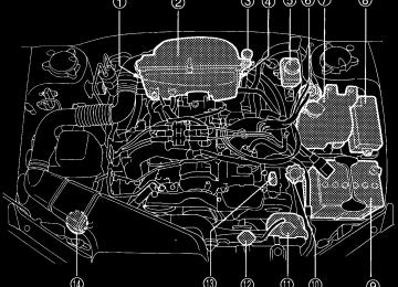
Vehicle identification
Specifications
HBD002BB
1 Emission control label 2 Vehicle identification number 3 Radio noise label (Canada
4 Vacuum hose connections
model)
label
5 Tire inflation pressure label 6 Certification and bar cord
7 Vehicle identification number
label
plate
8 Model number plate
12
– CONTINUED –
12-15
Legacy U.S.A. (E)
Consumer information and Reporting safety defects
Uniform tire quality grading standards
Treadwear Traction AA, A, B, C Temperature A, B, C
. . . . . . . . . . . . . . . . . . . . . . . . . . . . . . . . . . . . . . . . . . . . . . . . . . . . . . . . . . . . . . . . . . . . . . . . . . . . . . . . . . . . . . . . . . . . . . . . . . . . . . . . . . . . . . . . . . . . . . . . . . . . . . . . . . . . . . . . . . . . . . . . . . . . . . . . . . . . . . . . . . . . . . . . . . . . . . . . . . . . . . . . . . . . . . . . . . . . . . .
Reporting safety defects (USA)
. . . . . . . . . . . . . . . . . . . . . . . . . . . . . . . . . . . . . .
13-2
13-2
13-2
13-3
13-413
Legacy U.S.A. (E)
For U.S.A. The following information has been compiled according to Code of Fed- eral Regulations “Title 49, Part 575”.
Uniform tire quality grading standards
This information indicates the relative performance of passenger car tires in the area of treadwear, traction, and temperature resistance. This is to aid the consumer in making an informed choice in the purchase of tires. Quality grades can be found where applicable on the tire sidewall be- tween tread shoulder and maximum section width. For example:
Treadwear 200 Traction AA Temperature A
The quality grades apply to new pneumatic tires for use on passenger cars. However, they do not apply to deep tread, winter type snow tires, space-saver or temporary use spare tires, tires with nominal rim diame- ters of 12 inches or less, or to some limited production tires.
All passenger car tires must confirm to Federal Safety Requirements in addition to these grades.
J Treadwear The treadwear grade is a comparative rating based on the wear rate of the tire when tested under controlled conditions on a specified govern- ment test course. For example, a tire graded 150 would wear one and one-half (1-1/2) times as well on the government course as a tire graded 100. The rela- tive performance of tires depends upon the actual conditions of their use, however, and may depart significantly from the norm due to varia- tions in driving habits, service practices and differences in road charac- teristics and climate.
J Traction AA, A, B, C The traction grades, from highest to lowest, are AA, A, B and C. Those grades represent the tire’s ability to stop on wet pavement as measured under controlled conditions on specified government test surfaces of as-
13-2
Legacy U.S.A. (E)
Consumer information and Reporting safety defects
phalt and concrete. A tire marked C may have poor traction perfor- mance.
WARNING
The traction grade assigned to this tire is based on straight- ahead braking traction tests, and does not include acceleration, cornering, hydroplaning, or peak traction characteristics.
J Temperature A, B, C The temperature grades are A (the highest), B, and C, representing the tire’s resistance to the generation of heat and its ability to dissipate heat when tested under controlled conditions on a specified indoor laboratory test wheel. Sustained high temperature can cause the material of the tire to degenerate and reduce tire life, and excessive temperature can lead to sudden tire failure. The grade C corresponds to a level of perfor- mance which all passenger car tires must meet under the Federal Motor Vehicle Safety Standards No. 109. Grades B and A represent higher lev- els of performance on the laboratory test wheel than the minimum re- quired by law.
WARNING
The temperature grade for this tire is established for a tire that is properly inflated and not overloaded. Excessive speed, under- inflation, or excessive loading, either separately or in combina- tion, can cause heat buildup and possible tire failure.
13
– CONTINUED –
13-3
Legacy U.S.A. (E)
Reporting safety defects (USA)
If you believe that your vehicle has a defect which could cause a crash or could cause injury or death, you should immediately inform the National Highway Traffic Safety Ad- ministration (NHTSA) in addition to notifying Subaru of America, Inc. If NHTSA receives similar complaints, it may open an inves- tigation, and if it finds that a safety defect exists in a group of vehicles, it may order a recall and remedy campaign. However, NHTSA cannot become involved in individual problems between you, your dealer, or Subaru of America, Inc. To contact NHTSA, you may either call the Auto Safety Hotline toll-free at 1-800-424-9393 (or 366-0123 in the Washington D.C. area) or write to: NHTSA, U.S. Department of Transportation, Washington, D.C. 20590. You can also obtain other information about motor vehicle safety from the Hotline.
13-4