- 2003 Subaru Impreza Owners Manuals
- Subaru Impreza Owners Manuals
- 2010 Subaru Impreza Owners Manuals
- Subaru Impreza Owners Manuals
- 2000 Subaru Impreza Owners Manuals
- Subaru Impreza Owners Manuals
- 2009 Subaru Impreza Owners Manuals
- Subaru Impreza Owners Manuals
- 2008 Subaru Impreza Owners Manuals
- Subaru Impreza Owners Manuals
- 2004 Subaru Impreza Owners Manuals
- Subaru Impreza Owners Manuals
- 2012 Subaru Impreza Owners Manuals
- Subaru Impreza Owners Manuals
- 2013 Subaru Impreza Owners Manuals
- Subaru Impreza Owners Manuals
- 2002 Subaru Impreza Owners Manuals
- Subaru Impreza Owners Manuals
- 2001 Subaru Impreza Owners Manuals
- Subaru Impreza Owners Manuals
- Download PDF Manual
-
1. Remove the side sill cover on the driver’s side.
1)Open the driver’s door. 2)Remove the clip by prying the edge with screw- driver. 3)Remove the side sill cover by pulling it up.
2-16
WARNING
Do not disconnect or tamper with any yellow connector and/or any harness covered with yellow insulation and/or tape. Doing so could result in accidental inflation of the SRS airbag or could make the SRS airbag system inoperative, which may result in seri- ous injury.
B Arming the system 1. Turn the ignition switch to the “ON” position.
1) ON
2) LOCK
HB2031BC
IMPREZA(NA) A1830BE-A (ENGLISH)
Keys and doors
2. Turn the ignition switch from “ON” to “LOCK” position and remove the key from the ignition switch.
HB2024DB
3. Open the doors and get out of the vehicle. 4. Before closing the doors, lock all doors with the inside door lock levers. 5. Close the doors. The system will automatically arm after one minute. In the passive mode, the system can also be armed with the remote transmitter or with the power door locking switches. If the remote transmitter or power door lock switch is used to lock the vehicle, arming will take place immediately regardless of whether or not the passive mode has been selected.
– CONTINUED – 2-17
IMPREZA(NA) A1830BE-A (ENGLISH)
The indicator light provides the following indications. Flashing one time: Any door, the rear gate or the trunk lid has been opened. Flashing three times: The impact sensor in the sys- tem’s unit has been activated. This may indicate that your vehicle has been shocked or tampered with by some outside force and/or unauthorized person. Flashing four times: The ignition switch has been turned on or the battery has been disconnected. To exit this mode, close the door and turn the igni- tion switch to the “ON” position.
Keys and doors
CAUTION
In passive mode, the system will automatically activate the alarm but WILL NOT automatically lock the doors. In order to lock the doors you must either lock them as indicated in step 4
below or with the key once they have been closed. Failure to lock the doors manually will result in a higher security risk.B Disarming the system To disarm the system, briefly press the “UNLOCK/ DISARM” button on the transmitter. n Tripped sensor identification If the horn sounds four times and the parking lights flash four times when you disarm the system, this in- dicates that the alarm was triggered. The number of times the indicator light flashes indicates what sen- sor caused the alarm condition. To enter identification mode: 1. Open the driver’s door and leave it open. 2. Turn the ignition switch to the “ON” position two times. (“LOCK” → “ON” → “LOCK” → “ON” → “LOCK”) 3. The indicator light will start flashing.
2-18
IMPREZA(NA) A1830BE-A (ENGLISH)
Keys and doors
Child safety locks
WARNING
Each rear door has a child safety lock that prevents the doors from being opened even if the inside door handle is pulled.
Always use the child safety lock whenever a child rides in the rear seat. Serious injury could result if a child accidentally opened the door and fell out.
HG2006BB
1) Lock
2) Unlock
When the child safety lock lever is in the lock posi- tion, the door cannot be opened from inside regard- less of the position of the inner door handle lock lever. The door can only be opened from the out- side.
– CONTINUED – 2-19
IMPREZA(NA) A1830BE-A (ENGLISH)
B Driver’s side switches
HG2016BB
1) Lock switch 2) “AUTO” switch for driver’s window 3) For front passenger’s window 4) For rear left window 5) For rear right window
All door windows can be controlled by the power window switch cluster at the driver side door.
Keys and doors
Windows
J Power windows
WARNING
D When operating the power windows, be ex- tremely careful to prevent anyone’s fingers, arms or head from being caught in the win- dow. D Always lock the passengers’ windows using the lock switch when children are riding in the vehicle. D Before leaving the vehicle, always remove the key from the ignition switch for safety and never allow an unattended child to remains in the vehicle. Failure to follow this procedure could result in injury to a child operating the power window.
The power windows operate only when the ignition switch is in the “ON” position.
2-20
IMPREZA(NA) A1830BE-A (ENGLISH)
Keys and doors
n Operating the driver’s window
n Operating the passengers’ windows
HG2008DB
HG2008CA
1) Open 2) Automatically open 3) Close
AUTO switch: This switch has two functions. 1. Push the switch down until it clicks and release it, and the window will fully open. To stop the window halfway, pull the switch up lightly. 2. Push the switch down lightly and hold it. The win- dow will open as long as the switch is held. Pull the switch up lightly and hold it. The window will close as long as the switch is held.
To open the passengers’ windows, push the ap- propriate switch down and hold it until the window reaches the desired position. To close the window, pull the switch up and hold it until it reaches the de- sired position.
– CONTINUED – 2-21
IMPREZA(NA) A1830BE-A (ENGLISH)
Keys and doors
n Locking the passengers’ windows
“LOCK” position, the passengers’ windows cannot be operated with the passengers’ switches.
HG2013BB
1) Lock
2) Unlock
To lock the passengers’ windows, push the lock switch. When the lock switch is in the “LOCK” posi- tion, the passengers’ windows cannot be opened or closed. B Passengers’ side switches To open the window, push the switch down and hold it until the window reaches the desired position. To close the window, pull the switch up and hold it until the window reaches the desired position. When the lock switch on the power window switch cluster, located on the driver’s side door, is in the
2-22
IMPREZA(NA) A1830BE-A (ENGLISH)
Keys and doors
Trunk lid (Sedan)
J To open and close the trunk lid from
outside
WARNING
D To prevent dangerous exhaust gas from en- tering the vehicle, always keep the trunk lid closed while driving. D Help prevent young children from locking themselves in the trunk. When leaving the ve- hicle, either close all windows and lock all doors or cancel the inside trunk lid release. Also make certain that the trunk is closed. On hot or sunny days, the temperature in the trunk could quickly become high enough to cause death or serious heat-related injuries including brain damage, particularly for small children.
HGF012CA
To open the trunk lid from outside, insert the key and turn it clockwise. To close the trunk lid, lightly press the trunk lid down until the latch engages.
– CONTINUED – 2-23
IMPREZA(NA) A1830BE-A (ENGLISH)
Keys and doors
J To open the trunk lid from inside
J To cancel the trunk lid release
HB3000CC
HG2009BA
1) Open
Pull the trunk lid release lever upward.
The inside trunk lid release can be cancelled to help prevent unauthorized entry into the trunk. To cancel the trunk lid release, set the lid release cancel lever (located on the inside of the trunk lid, mounted to the trunk lid latch) to the “CANCEL” position. When this lock is in the “CANCEL” position, the trunk can be opened only with the key.
2-24
J Trunk lid release handle The trunk lid release handle is a device designed to open the trunk lid from inside the trunk. In the event children or adults become locked inside the trunk, the handle allows them to open the lid. The handle is located on the inside of the trunk lid. To open the trunk lid from inside the trunk, press the yellow handle downward as indicated by the arrow on the handle.
HBS070BA
This operation unlocks the trunk lid. Then, push up the lid. The handle is made of material that remains lumi- nescent for approximately an hour in the dark trunk space after it is exposed to ambient light even for a
IMPREZA(NA) A1830BE-A (ENGLISH)
Keys and doors
short time.
WARNING
Never allow any child to get in the trunk and play with the release handle. If the driver starts the vehicle without knowing that a child is inside the trunk and the child opens the lid using the release handle, the child could fall out and be killed or seriously injured.
CAUTION
D Do not close the lid while gripping the re- lease handle. The handle may be damaged. D Do not use the handle as a hook to fasten straps or ropes to secure your cargo in the trunk. Such use may result in damage of the handle. D Load the trunk so that cargo can not strike the release handle. If the cargo hits the handle while the vehicle is being driven, the handle may be pushed down and the trunk lid may open. That may cause cargo to fall out of the trunk, which could create a traffic safety haz- ard.
– CONTINUED – 2-25
IMPREZA(NA) A1830BE-A (ENGLISH)
HBS072BA
3. Move the release handle, from outside the ve- hicle, in the direction of the arrow to check if the latch is released.
HG2018BA
Keys and doors
B Inspection Perform the following steps at least twice a year to check the release handle for correct operation. 1. Open the trunk lid. 2. Use a screwdriver with a thin blade. Slide the screwdriver blade from the slit aperture of the lock assembly fully to the end until you hear a click.
This places the latch in the locked position.
HBS071BA
2-26
IMPREZA(NA) A1830BE-A (ENGLISH)
Rear gate (Wagon)
Keys and doors
If the latch is not released, contact your SUBARU dealer. In that case, use the key to release the latch, then close the trunk lid. Also, if the movements of the release handle feel re- stricted or not entirely smooth during operation, or the handle and/or handle base is cracked, contact your SUBARU dealer.
HGF013EB
1) Lock
2) Unlock
To unlock the rear gate, insert the key in the keyhole and turn it clockwise. To lock the rear gate, insert the key in the keyhole and turn it counterclockwise. If your vehicle is equipped with power door locking switches, the rear gate can also be locked and unlocked through use of the power door locking switches. Refer to the “Power door locking switches” section in this chapter. To open the rear gate, first unlock the rear gate lock then pull the outside handle up. To close the rear gate, lower it slowly and push down firmly until the – CONTINUED – 2-27
IMPREZA(NA) A1830BE-A (ENGLISH)
Keys and doors
latch engages.
WARNING
To prevent dangerous exhaust gas from enter- ing the vehicle, always keep the rear gate closed while driving.
2-28
Ignition switch
LOCK ACC ON START Key reminder chime Key interlock release (AT vehicles only)
. . . . . . . . . . . . . . . . . . . . . . . . . . . . . . . . . . . . . . . . . . . . . . . . . . . . . . . . . . . . . . . . . . . . . . . . . . . . . . . . . . . . . . . . . . . . . . . . . . . . . . . . . . . . . . . . . . . . . . . . . . . . . . . . . . . . . . . . . . . . . . . . . . . . . . . . . . . . . . . . . . . . . . . . . . . . . . . . . . . . . . . . . . . . . . . . . . . . . . . . . . . . . . . . . . . . . . . . . . . . . . . . . . . . . . . . . . . . . . . . . . . . . . . . . . . . . . . . . . . . . . . . . . . . . . . . . . . . . . . . . . . . . . . . . . . . . . . . . . . . . . . . . . . . . . . . . . . . . . . . . . . . . . . . . . . . . . . . . . . . . . . . . . . . . . . . . . . . . . . . . . . . . . . . . . . . . . . . . . . . . . . . . . . . . . . . . . . . . . . . . . . . . . . . . . . . . . . . . . . . . . . . . . . . . . . . . . . . . . . . . . . . . . . . . . . . . . . . . . . . . . . . . . . . . . . . . . . . . . . . . . . . . . . . . . . . . . . . . . . . . . . . . . . . . . . . . . . . .
Speedometer Odometer/Trip meter Tachometer Fuel gauge Temperature gauge Outside temperature indicator
Hazard warning flasher Meters and gauges
(if equipped)
Warning and indicator lights
. . . . . . . . . . . . . . . . . . . . . . . . . . . . . . . . . . . . . . . . . . . . . . . . . . . . . . . . . . . . . . . . . . . . . . . . . . . . . . . . . . . . . . . .
Seatbelt warning light and chime SRS airbag system warning light CHECK ENGINE warning light/
Malfunction indicator lamp
Charge warning light Oil pressure warning light AT OIL TEMPerature warning light
. . . . . . . . . . . . . . . . . . . . . . . . . . . . . . . . . . . . . . . . . . . . . . . . . . . . . . . . . . . . . . . . . . . . . . . . .
(for AT vehicles) ABS warning light Brake system warning light Door open warning lights
. . . . . . . . . . . . . . . . . . . . . . . . . . . . . . . . . . . . . . . . . . . . . . . . . . . . . . . . . . . . . . . . . . . . . . . . . . . . . . . . . . . . . . . . . . . . . . . . . . . . . . . . . . . . . . .
IMPREZA(NA) A1830BE-A (ENGLISH)
Instruments and controls
Front-wheel drive warning light (for AT vehicles – if equipped)
Clock Light control switch
Shift position indicator (AT vehicles) Turn signal indicator lights High beam indicator light
Headlights High/low beam change (dimmer) Headlight flasher Daytime running light system
. . . . . . . . . . . . . . . . . . . . . . . . . . . . . . . . . . . . . . . . . . . . . . . . . . . . . . . . . . . . . . . . . . . . . . . . . . . . . . . . . . . . . . . . . . . . . . . . . . . . . . . . . . . . . . . . . . . . . . . . . . . . . . . . . . . . . . . . . . . . . . . . . . . . . . . . . . . . . . . . . . . . . . . . . . . . . . . . . . . . . . . . . . . . . . . . . . . . . . . . . . . . . . . . . . . . . . . . . . . . . . . . . . . . . . . . . . . . . . . . . . . . . . . . . . . . . . . . . . . . . . . . . . . . . . . . . . . . . . . . . . . . . . . . . . . . . . . . . . . . . . . . . . . . . . . . . . . . . . . . . . . . . . . . . . . . . . . . . . . . . . . . . . . . . . . . . . . . . . . . . . . . . . . . . . . . . . . . . . . . . . . . . . . . . . . . . . . . . . . . . . . . . . . . .
Turn signal lever Illumination brightness control Parking light switch Fog light switch (if equipped) Wiper and washer
Windshield wiper and washer switches Rear window wiper and washer switch
(if equipped)
Rear window defogger switch Mirrors
. . . . . . . . . . . . . . . . . . . . . . . . . . . . . . . . . . . . . . . . . . . . . . . . . . . . . . . . . . . . . . . . . . . . . . . . . . . . . . . . . . . . . . . . . . . . . . . . . . . . . . . . . . . . . . . . . . . . . . . . . . . . . . . . . . . . . . . . . . . . . . . . . . . . . . . . . . . . . . . . . . . . . . . . . . . . . . . . . . . . . . . . . . . . . . . . . . . . . . . . . . . . . . . . . . . . . . . . . . . . . . . . . . . . . . . . . . . . . . . . . . . . . . . . . . . . . . . . . . . . . . . . . . . . .
Tilt steering wheel Horn
Inside mirror Outside mirrors
3-14
3-14
3-14
3-14
3-14
3-15
3-15
3-16
3-16
3-17
3-17
3-18
3-19
3-19
3-20
3-213-23
3-24
3-25
3-25
3-28
3-30
3-31– CONTINUED – 3-1
3-2
3-2
3-3
3-3
3-3
3-3
3-4
3-5
3-6
3-6
3-6
3-7
3-7
3-83-9
3-9
3-9
3-103-10
3-11
3-113-12
3-12
3-13
3-13Instruments and controls
Ignition switch
IMPREZA(NA) A1830BE-A (ENGLISH)
B Automatic transmission vehicles
HB3014BA
The ignition switch has four positions: LOCK, ACC, ON and START.
J LOCK The key can only be inserted or removed in this position. The ignition switch will lock the steering wheel when you remove the key. If turning the key is difficult, turn the steering wheel slightly to the right and left as you turn the key.
3-2
HB4016BA
The key can be turned from “ACC” to “LOCK” only
HB2032CA
IMPREZA(NA) A1830BE-A (ENGLISH)
Instruments and controls
when the selector lever is in the “P” position. B Manual transmission vehicles
J ACC In this position the electrical accessories (radio, cig- arette lighter, etc.) can be used.
J ON This is the normal operating position after the engine is started.
J START The engine is started in this position. The starter cranks the engine to start it. When the key is re- leased (after the engine has started), the key auto- matically returns to the “ON” position.
OM-H0144
The key can be turned from “ACC” to “LOCK” only when the key is pushed in while turning it.
CAUTION
WARNING
Never turn the ignition switch to “LOCK” while the vehicle is being driven or towed be- cause that will lock the steering wheel, pre- venting steering control. And when the engine is turned off, it takes a much greater effort than usual to steer.
Do not turn the ignition switch to the “START” position while the engine is running.
J Key reminder chime The reminder chime sounds when the driver’s door opens and the key is in the “LOCK” or “ACC” posi- tions. The chime stops when the key is removed from the ignition switch.
– CONTINUED – 3-3
Instruments and controls
J Key interlock release (AT vehicles
only)
If the key can not be turned to the “LOCK” position even when the selector lever is in the “P” position: 1. Take out the screwdriver from the tool bag.
IMPREZA(NA) A1830BE-A (ENGLISH)
HB3012BA
2. Remove the cover under the steering column us- ing a phillips screwdriver.
HB3011BA
3-4
OM-H0146
F) Vehicle front
2) Release lever
3. Turn the ignition key while pressing the key inter- lock release lever.
IMPREZA(NA) A1830BE-A (ENGLISH)
Instruments and controls
Take your vehicle to the nearest SUBARU dealer im- mediately to have the key interlock system repaired.
Hazard warning flasher
HG3004AA
The hazard warning flasher is used to warn other drivers when you have to park your vehicle under emergency conditions. The hazard warning flasher works with the ignition switch in any position. To turn on the hazard warning flasher, push the haz- ard warning button on the instrument panel. To turn off the flasher, push the button again. NOTE When the hazard warning flasher is on, the turn signals do not work.
– CONTINUED – 3-5
IMPREZA(NA) A1830BE-A (ENGLISH)
Instruments and controls
Meters and gauges
B Double trip meter
J Speedometer The speedometer shows the vehicle speed.
J Odometer/Trip meter
HG3006BB
1) A trip meter
2) B trip meter
The trip meter shows the distance that the vehicle has been driven since you last set it to zero. To change the mode indication, briefly push the knob. Each press of the knob changes the function in the following order.
A trip meter
B trip meter
To set the trip meter to zero, select the A trip or B trip meter by pushing the knob and keep the knob pushed for more than 2 seconds.
HG3005BB
1) Trip meter
2) Odometer
This meter displays the odometer and two trip me- ters when the ignition switch is in the “LOCK”, “ACC” or “ON” position. B Odometer The odometer shows the total distance that the ve- hicle has been driven.
3-6
IMPREZA(NA) A1830BE-A (ENGLISH)
Instruments and controls
CAUTION
J Fuel gauge
To ensure safety, do not attempt to change the function of the indicator during driving, as an accident could result.
NOTE If the connection between the combination meter and battery is broken for any reason such as ve- hicle maintenance or fuse replacement, the data recorded on the trip meter will be lost.
J Tachometer The tachometer shows the engine speed in thou- sands of revolutions per minute.
CAUTION
Do not operate the engine with the pointer of the tachometer in the red zone. In this range, fuel injection will be cut by the engine control module to protect the engine from overrev- ving. The engine will resume running normally after the engine speed is reduced below the red zone.
HG3007BB
1) Low fuel warning light
The fuel gauge shows the approximate amount of fuel remaining in the tank. The gauge does not return to “E” even though the ignition switch is in the “ACC” or “LOCK” position. The gauge may move slightly during braking, turn- ing or acceleration due to fuel level movement in the tank.
– CONTINUED – 3-7
Instruments and controls
NOTE
IMPREZA(NA) A1830BE-A (ENGLISH)
about 4.0 U.S. gal. (15 liters, 3.3 Imp. gal.).
J Temperature gauge
HG3016AA
You will see the “FUEL DOOR p” sign near the fuel gauge. This indicates that the fuel filter door (lid) is located on the right side of the vehicle.
B Low fuel warning light The low fuel warning light comes on when the tank is nearly empty [about 2.3 U.S. gal. (9.0 liters, 1.9
Imp. gal.]. It only operates when the ignition switch is in the “ON” position. NOTE This light does not go out unless the tank is replenished up to an internal fuel quantity of3-8
HG3008BB
1) Normal operating range
The temperature gauge shows engine coolant tem- perature when the ignition switch is in the “ON” posi- tion. The coolant temperature will vary in accordance with the outside temperature and driving conditions. We recommend that you drive moderately until the pointer of the temperature gauge reaches near the middle of the range. Engine operation is optimum with the engine coolant at this temperature range
IMPREZA(NA) A1830BE-A (ENGLISH)
Instruments and controls
and high revving operation when engine is not warmed up enough should be avoided.
Warning and indicator lights
CAUTION
If the pointer exceeds the normal operating range, safely stop the vehicle as soon as pos- sible. See the “In case of emergency” in chapter 9.
J Outside temperature indicator
(if equipped)
The outside temperature indicator shows the outside temperature in a range from –22°F to 122°F (–30°C to 50°C). The indicator can give a false reading under any of the following conditions: D When there is too much sun. D During idling; while running at low speeds in a traffic jam; when the engine is restarted immediately following a shutdown. D When the actual outside temperature falls outside the specified indicator range.
Several of the warning and indicator lights come on momentarily and then go out when the ignition switch is initially turned to the “ON” position. This permits checking the operation of the bulbs. Apply the parking brake and turn the ignition switch to the “ON” position. The following lights come on:
Seatbelt warning light SRS airbag system warning light CHECK ENGINE warning light/Malfunction indica- tor lamp Charge warning light Oil pressure warning light AT OIL temperature warning light (AT vehicles) ABS warning light Brake system warning light
If any lights fail to come on, it indicates a burned-out bulb or a malfunction of the corresponding system. Consult your authorized SUBARU dealer for repair.
J Seatbelt warning light and chime When the ignition switch is turned to the “ON” posi- tion, the seatbelt warning light will come on and the reminder chime will sound for about six seconds to remind the driver to fasten the seatbelt.
– CONTINUED – 3-9
IMPREZA(NA) A1830BE-A (ENGLISH)
J CHECK ENGINE warning light/
Malfunction indicator lamp
CAUTION
If the CHECK ENGINE light comes on while you are driving, have your vehicle checked/re- paired by your SUBARU dealer as soon as possible. Continued vehicle operation without having the emission control system checked and repaired as necessary could cause seri- ous damage, which may not be covered by your vehicle’s warranty.
If this light comes on steadily or blinks while the en- gine is running, it may indicate that there is a prob- lem or potential problem somewhere in the emission control system. B If the light comes on steadily: If the light comes on steadily while driving or does not go out after the engine starts, an emission con- trol system malfunction has been detected. You should have your vehicle checked by an autho- rized SUBARU dealer immediately.
Instruments and controls
The seatbelt warning light remain on for about six seconds and turn off automatically after six seconds. The seatbelt reminder chime will turn off by bucking the driver’s side seatbelt or turn off automatically after six seconds.
J SRS airbag system warning
light
AIRBAG When the ignition switch is turned to the “ON” posi- tion, the SRS airbag system warning light will come on for about six seconds and go out. This shows the SRS airbag and SRS side airbag (if equipped) and seatbelt pretensioners are in normal operation. If this light comes on while driving or remains illumi- nated even after a period of about 6 seconds from when the ignition has been turned on, it may indi- cate that the SRS airbag system or SRS side airbag system (if equipped) or seatbelt pretensioner sys- tem is not working properly. Contact your nearest SUBARU dealer immediately.
3-10
NOTE This light also comes on when the fuel filler cap is not tightened until it clicks. If you have recently refueled your vehicle, the cause of the CHECK ENGINE warning light/malfunction indi- cator lamp coming on could be a loose or missing fuel filler cap. Remove the cap and retighten it until it clicks. Make sure nothing is interfering with the seal- ing of the cap. Tightening the cap will not make the CHECK ENGINE warning light turn off immediately. It may take several driving trips. If the light does not go out, take your vehicle to your authorized SUBARU dealer immediately. B If the light is blinking: If the light is blinking while driving, an engine misfire condition has been detected which may damage the emission control system. To prevent serious damage to the emission control system, you should do the following:
D Reduce vehicle speed. D Avoid hard acceleration. D Avoid steep uphill grades. D Reduce the amount of cargo, if possible. D Stop towing a trailer as soon as possible.
IMPREZA(NA) A1830BE-A (ENGLISH)
Instruments and controls
The CHECK ENGINE warning light may stop blink- ing and come on steadily after several driving trips. You should have your vehicle checked by an autho- rized SUBARU dealer immediately.
J Charge warning light If this light comes on when the engine is running, it may indicate that the charging system is not work- ing properly. If the light comes on while driving or does not go out after the engine starts, stop the engine at the first safe opportunity and check the alternator belt. If the belt is loose, broken or if the belt is in good condi- tion but the light remains on, contact your nearest SUBARU dealer immediately.
J Oil pressure warning light If this light comes on when the engine is running, it may indicate that the engine oil pressure is low and the lubricating system is not working properly. If the light comes on while driving or does not go out after the engine starts, stop the engine at the first safe opportunity and check the engine oil level. If the oil level is low, add oil immediately. If the engine oil is at the proper level but the light remains on, contact your nearest SUBARU dealer immediately.
– CONTINUED – 3-11
Instruments and controls
CAUTION
Do not operate the engine with the oil pres- sure warning light on. This may cause serious engine damage.
J AT OIL TEMPerature warning
light (for AT vehicles)
If this light comes on when the engine is running, it may indicate that the automatic transmission fluid temperature is too hot. If the light comes on while driving, it is unnecessary to stop the vehicle, but avoid driving up steep grades or in stop and go traffic. B Automatic transmission control system warn-
ing
If the light flashes after the engine starts, it may indi- cate that the automatic transmission control system is not working properly. Contact your nearest SUBARU dealer for service immediately.
(U.S.) J ABS warning light (Canada) The ABS warning light comes on when the ignition switch is turned to the “ON” position and goes out
3-12
IMPREZA(NA) A1830BE-A (ENGLISH)
after about two seconds. This is an indication that the ABS system is working properly.
CAUTION
If the warning light behaves as follows, the ABS system may not work properly. When the warning light is on, the ABS func- tion shuts down; however, the conventional brake system continues to operate normally. D The warning light does not come on when the ignition switch is turned to the “ON” posi- tion. D The warning light comes on when the igni- tion switch is turned to the “ON” position, but it does not go out even when the vehicle speed exceeds approximately 8 mph (12
km/h). D The warning light comes on during driving. If these occur, have the ABS system repaired at the first available opportunity by your SUBARU dealer.NOTE If the warning light behavior is as shown below, the ABS system may be considered normal.
D The warning light comes on right after the engine is started but goes out immediately, remaining off. D The warning light remains on after the engine has been started, but it goes out when the vehicle speed reaches about 8 mph (12 km/h). D The warning light comes on during driving, but it goes out immediately and remains off. When driving with an insufficient battery voltage such as when the engine is jump started, the ABS warning light may come on. This is due to the low battery voltage and does not indicate a malfunction. When the battery becomes fully charged, the light will go out.
J Brake system warning
light
(U.S.)
(Canada)
CAUTION
D Driving with the brake system warning light on is dangerous. This indicates your brake system may not be working properly. If the light remains on, have the brakes inspected by a SUBARU dealer immediately. D If at all in doubt about whether the brakes
IMPREZA(NA) A1830BE-A (ENGLISH)
Instruments and controls
are operating properly, do not drive the ve- hicle. Have your vehicle towed to the nearest SUBARU dealer for repair.
This light has the following two functions: B Parking brake warning The light comes on with the parking brake applied while the ignition switch is in the “ON” position. It goes out when the parking brake is fully released. B Brake fluid level warning This light comes on when the brake fluid level has dropped to near the “MIN” level of the brake fluid reservoir with the ignition switch in the “ON” position and with the parking brake fully released. If the brake system warning light should come on while driving (with the parking brake fully released and with the ignition switch positioned in “ON”), it could be an indication of leaking of brake fluid or worn brake pads. Have your vehicle checked by a SUBARU dealer immediately.
J Door open warning lights The door open warning light comes on if any door or the rear gate is not fully closed.
– CONTINUED – 3-13
IMPREZA(NA) A1830BE-A (ENGLISH)
Instruments and controls
Always make sure this light is out before you start to drive.
Clock
J Front-wheel drive warning light
(for AT vehicles – if equipped)
This light comes on when All Wheel Drive is disen- gaged and the drive mechanism is switched to Front Wheel Drive for maintenance or similar purposes.
J Shift position indicator (AT vehicles) This indicator shows the position of the shift lever.
J Turn signal indicator lights These lights show the operation of the turn signal or lane change signal. If the indicator lights do not blink or blink rapidly, the turn signal bulb may be burned out. Replace the bulb as soon as possible. Refer to the “Replacing bulbs” section in chapter 11.
J High beam indicator light This light shows that the headlights are in the high beam mode. This indicator light also comes on when operating headlight flasher.
3-14
1) “S” button 2) “H” button
HG3009BB
3) “M” button
To set the hour, press the “H” button. To set the min- utes, press the “M” button. To reset the minutes the “00” with a radio time signal, push the “S” button.
CAUTION
To ensure safety, do not attempt to set the time during driving, as an accident from inad- equate steering operation could result.
IMPREZA(NA) A1830BE-A (ENGLISH)
Instruments and controls
Light control switch
J Headlights
The light switch operates only when the ignition switch is in the “ON” position.
WARNING
To prevent battery discharge resulting from accidentally leaving your lights on when your vehicle is parked, the light switch operates only when the ignition switch is in the “ON” position. In any other position, the vehicle’s lights will be out. If you park your vehicle on a roadside at night, use the hazard warning flasher to alert the other drivers.
HB2007BA
To turn on the headlights, turn the knob on the end of the turn signal lever.
first position
Parking lights, instrument panel illumination, tail lights and license plate light are on.
second position
Headlights, parking lights, instrument panel illumina- tion, tail lights, and license plate light are on.
– CONTINUED – 3-15
IMPREZA(NA) A1830BE-A (ENGLISH)
Instruments and controls
J High/low beam change (dimmer)
J Headlight flasher
HG3014CA
HG3014BA
To change from low beam to high beam, push the turn signal lever forward. When the headlights are on high beam, the high beam indicator light “a” on the instrument panel is also on. To switch back to low beam, pull the lever back to the detent position.
To flash the headlights, pull the lever toward you and then release it. The high beam will stay on for as long as you hold the lever. The headlight flasher works even though the lighting switch is in the “OFF” position. When the headlights are on high beam, the high beam indicator light “a” on the instrument panel also comes on.
CAUTION
Do not hold the lever in the flashing position for more than just a few seconds.
3-16
IMPREZA(NA) A1830BE-A (ENGLISH)
Instruments and controls
J Daytime running light system
Turn signal lever
WARNING
The tail lights, parking lights, and side marker lights are not turned on by the daytime run- ning light system. The light switch must al- ways be turned to the “a” position when it is dark outside.
The low beam headlights will automatically come on at reduced brightness when the engine has started, under the following conditions: D The parking brake is fully released. D The light switch is in the “OFF” or “p” position. D The automatic transmission selector lever is set at other than the “P” position.
HB2015BC
1) Right turn 2) Left turn 3) Lane change for right 4) Lane change for left
To activate the right turn signal, push the turn signal lever up. To activate the left turn signal, push the turn signal lever down. When the turn is finished, the lever will return automatically. If the lever does not return after cornering, return the lever to the neutral position by hand. To signal a lane change, push the turn signal lever up or down slightly and hold it during the lane change. The turn signal indicator lights will flash in – CONTINUED – 3-17
IMPREZA(NA) A1830BE-A (ENGLISH)
Instruments and controls
the direction of the turn or lane change. The lever will return automatically to the neutral position when you release it.
Illumination brightness control
When the lighting switch is in the “p” or “a” position, you can adjust brightness of the instrument panel illumination for better visibility.
HB2017BC
1) To brighten, turn the control dial coun-
2) To darken, turn the control dial clock-
terclockwise.
wise.
3-18
IMPREZA(NA) A1830BE-A (ENGLISH)
Instruments and controls
Parking light switch
Fog light switch (if equipped)
The fog lights operate only when the headlights are on low beam. Push the fog light switch to turn the fog lights on. Press the switch again to turn them off.
HB2018BA
The parking light switch operates regardless of the ignition switch position. By pushing the front end of this switch, following lights will come on. – Parking lights – Tail lights – License plate lights To turn off, push the rear end of the parking light switch. Avoid leaving these lights on for a long time be- cause that will run down the battery.
HB2025BC
1) Indicator light
The indicator light located on the switch will illumi- nate when the fog lights are on.
– CONTINUED – 3-19
Instruments and controls
Wiper and washer
WARNING
In freezing weather, do not use the windshield washer until the windshield is sufficiently warmed by the defroster. Otherwise the washer fluid can freeze on the windshield, blocking your view.
CAUTION
D Do not operate the washer continuously for more than ten seconds, or when the washer fluid tank is empty. This may cause overheat- ing of the washer motor. Check the washer fluid level frequently, such as at fuel stops. D Do not operate the wipers when the wind- shield or rear window is dry. This may scratch the glass, damage the wiper blades and cause the wiper motor to burn out. Before operating the wiper on a dry windshield or rear window, always use the windshield washer. D In freezing weather, be sure that the wiper blades are not frozen to the windshield or rear
3-20
IMPREZA(NA) A1830BE-A (ENGLISH)
window before switching on the wipers. Attempting to operate the wiper with the blades frozen to the window glass could cause not only the wiper blades to be dam- aged but also the wiper motor to burn out. If the wiper blade is frozen to the window glass, be sure to operate the defroster, windshield wiper deicer (if equipped) or rear window defogger before turning on the wiper. D If the wipers stop during operation because of ice or some other obstruction on the win- dow, the wiper motor could burn out even if the wiper switch is turned off. If this occurs, promptly stop the vehicle in a safe place, turn the ignition switch to the “LOCK” position and clean the window glass to allow proper wiper operation. D Use clean water if windshield washer fluid is unavailable. In areas where water freezes in winter, use SUBARU Windshield Washer Fluid or the equivalent. (See the “Windshield wash- er fluid” section in chapter 11.) Also, when driving the vehicle when there are freezing temperatures, use non-freezing type wiper blades. D Do not clean the wiper blades with gasoline or a solvent, such as paint thinner or benzene.
This will cause deterioration of the wiper blades.
NOTE D The wiper operates only when the ignition switch is in the “ON” or “ACC” position. D Clean your wiper blades and window glass periodically with a washer solution to prevent streaking, and to remove accumulations of road salt or road film. Keep the washer button depressed at least for 1 second so that washer solution will be sprinkled all over the windshield or rear window. D Grease, wax, insects or other material on the windshield or the wiper blade results in jerky wiper operation and streaking on the glass. If you cannot remove those streaks after operating the washer or if the wiper operation is jerky, clean the outer surface of the windshield or rear window and the wiper blades using a sponge or soft cloth with a neutral detergent or mild-abra- sive cleaner. After cleaning, rinse the window glass and wiper blades with clean water. The glass is clean if no beads form on the glass when you rinse with water. D If you cannot eliminate the streaking even after following this procedure, replace the wiper
IMPREZA(NA) A1830BE-A (ENGLISH)
Instruments and controls
blades with new ones. Refer to the “Wiper blade replacement” section (chapter 11) for replace- ment instructions.
J Windshield wiper and washer
switches
B Windshield wipers To turn the wipers on, push the wiper control lever down.
HG3010BB
1) OFF 2) Intermittent 3) LO : Low speed 4) HI : High speed
– CONTINUED – 3-21
IMPREZA(NA) A1830BE-A (ENGLISH)
Instruments and controls
To turn the wipers off, return the lever to the “OFF” position. B Wiper intermittent time control (if equipped)
B Mist (for a single wipe)
HB2023BA
For a single wipe of the wipers, pull the lever toward you. The wipers operate until you release the lever.
HG3011BA
” position, turn
When the wiper switch is in the “ the dial to adjust the operating interval of the wiper. Operating interval can be adjusted continuously from the shortest interval to the longest. Two click stop positions of the dial may help you to aim at your desired interval.
3-22
IMPREZA(NA) A1830BE-A (ENGLISH)
Instruments and controls
B Washer
J Rear window wiper and washer
switch (if equipped)
HB2020BA
To wash the windshield, push the washer button at the end of the wiper control lever. The washer fluid sprays until you release the washer button. The wip- ers operate while you push the button.
HB2021BB
1) Rear wiper
2) Washer
B Rear wiper The rear wiper offers intermittent operation only. To turn the rear wiper on, turn the knob on the end of the wiper control lever to the “ON” position. To turn the wiper off, return the knob on the end of the lever to the “OFF” position. B Washer To wash the rear window while the rear wiper is op- erating, turn the knob on the end of the wiper control ” position. The lever counterclockwise to the “
– CONTINUED – 3-23
Instruments and controls
washer fluid sprays until you release the knob. To wash the rear window when the rear wiper is not in use, turn the knob on the end of the wiper control ” position. The washer lever clockwise to the “ fluid sprays and the wiper operates until you release the knob.
IMPREZA(NA) A1830BE-A (ENGLISH)
Rear window defogger switch
The rear window defogger operates only when the ignition switch is in the “ON” position. The rear window defogger switch is located on the climate control panel. The defogger will automatically shut off after about 15 minutes. If the window clears before that time, push the switch to turn it off. It also turns off when the ignition switch is turned to the “ACC” or “LOCK” position. If defrosting or defogging is desired when you restart your vehicle, you have to push the switch to turn it on again.
3-24
1) OFF 2) ON
HB5009BC
3) Push
To turn on the defogger, push the switch. To turn it off, push the switch again. The indicator light located on the switch lights up while the rear window defogger is operating. NOTE If your vehicle is equipped with the outside mir- ror defogger, the outside mirror defogger oper- ates while the rear window defogger is operating.
CAUTION
D Do not use sharp instruments or window cleaner containing abrasives to clean the in- ner surface of the rear window. They may damage the conductors printed on the win- dow. D To prevent the battery from being dis- charged, do not operate the defogger continu- ously for any longer than necessary.
IMPREZA(NA) A1830BE-A (ENGLISH)
Instruments and controls
Mirrors
Always check that the inside and outside mirrors are properly adjusted before you start driving.
J Inside mirror
HB4003BC
1) Tab
The inside mirror has a day and night position. Pull the tab at the bottom of the mirror toward you for the night position. Push it away for the day position. The night position reduces glare from headlights.
– CONTINUED – 3-25
Instruments and controls
B Compass mirror (if equipped)
HB6019BC
1) Left button 2) Auto dimming indicator 3) Photosensor 4) Right button
The inside electronic compass mirror has an anti- glare feature which automatically reduces glare coming from headlights of vehicles behind you. It also contains a built-in compass. D By pressing and releasing the left button, the au- tomatic dimming function is toggled on or off. When the automatic dimming function is on, the auto dim- ming indicator light (green) located to the right of the button will illuminate.
3-26
IMPREZA(NA) A1830BE-A (ENGLISH)
D By pressing and releasing the right button, the compass display is toggled on or off. When the compass is on, an illuminated compass reading will appear in the lower part of the mirror. Even with the mirror in anti-glare mode, the mirror surface turns bright if the transmission is shifted into reverse. This is to ensure good rearward visibility during reversing. n Photosensors
HB6020BA
The mirror has a photosensor attached on both the front and back sides. If the glare from the headlights of vehicles behind you strikes the mirror, these sen- sors detect it and make the reflection surface of the mirror dimmer to help prevent you from being
blinded. For this reason, use care not to cover the sensors with stickers, or other similar items. Periodi- cally wipe the sensors clean using a piece of dry soft cotton cloth or an applicator. n Compass calibration 1. For optimum calibration, switch off all nonessen- tial electrical accessories (rear window defogger, heater/air conditioning system, spotlight, etc.) and ensure all doors are shut. 2. Drive to an open, level area away from large me- tallic objects or structures and make certain the igni- tion switch is in the “ON” position. 3. Press and hold the left button for 3 seconds then release, and the compass will enter the calibration mode. “CAL” and direction will be displayed. 4. Drive slowly in a circle until “CAL” disappears from the display (about two or three circles). 5. The compass is now calibrated. Further calibra- tion is not required. The compass will automatically calibrate from this point forward.
IMPREZA(NA) A1830BE-A (ENGLISH)
Instruments and controls
n Compass zone adjustment
HB6021AA
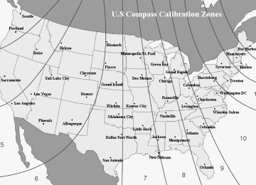
Compass calibration zones
1. The zone setting is factory preset to Zone 8. Re- fer to the “Compass calibration zone” map shown above or one attached to the end of this manual to verify that the compass zone setting is correct for your geographical location. 2. Press and hold the right button for 3 seconds then release, and the word “ZONE” will briefly ap- pear and then the zone number will be displayed. 3. Press the right hand button repeatedly to cycle the display through all possible zone settings. Stop cycling when the correct zone setting for your loca- tion is displayed.
– CONTINUED – 3-27
IMPREZA(NA) A1830BE-A (ENGLISH)
Instruments and controls
4. Releasing the button for 3 seconds will exit the zone setting mode.
tance of objects that you view in convex mir- ror.
J Outside mirrors
B Remote control mirror switch The remote control mirrors operate only when the ignition switch is in the “ON” or “ACC” position.
HS0065
B Convex mirror (passenger side)
HG3012BB
WARNING
1) Selection switch 2) Direction control switch
Objects look smaller in a convex mirror and farther away than when viewed in a flat mirror. Do not use the convex mirror to judge the dis- tance of vehicles behind you when changing lanes. Use the inside mirror (or glance back- wards) to determine the actual size and dis-
1. Press either end of the selection switch, “L” for the left, “R” for the right. 2. Move the direction control switch in the direction you want to move the mirror. 3. Return the selection switch to the neutral position to prevent unintentional operation.
3-28
The mirrors can also be adjusted manually. B Outside mirror defogger (if equipped) The outside mirror defogger shares the switch with rear window defogger. The outside mirror defogger operates only when the ignition switch is in the “ON” position.
1) OFF 2) ON
HB5009BC
3) Push
To turn on the outside mirror defogger, push the switch. To turn it off, push the switch again. The indi- cator light located on the switch lights up while the outside mirror defogger is operating. The defogger will automatically shut off after about
IMPREZA(NA) A1830BE-A (ENGLISH)
Instruments and controls
15 minutes. If the mirror clears before that time, push the switch to turn it off. It also turns off when the ignition switch is turned to the “ACC” or “LOCK” position. If defrosting or defogging is desired when you restart your vehicle, you have to push the switch to turn it on again. NOTE While the outside mirror defogger is operating, the rear window defogger also operates.
CAUTION
To prevent the battery from being discharged, do not operate the defogger continuously for any longer than necessary.
– CONTINUED – 3-29
Instruments and controls
Tilt steering wheel
IMPREZA(NA) A1830BE-A (ENGLISH)
WARNING
Do not adjust the steering wheel tilt position while driving. This may cause loss of vehicle control and result in personal injury.
HB4002BA
1. Adjust the seat position. Refer to the “Front seat” section (chapter 1). 2. Pull the tilt lock lever down. 3. Move the steering wheel to the desired level. 4. Push the lever up to lock the steering wheel in place. 5. Make sure that the steering wheel is securely locked by moving it up and down.
3-30
IMPREZA(NA) A1830BE-A (ENGLISH)
Instruments and controls
Horn
To sound the horn, push the horn pad.
OM-H0440
– CONTINUED – 3-31
even (left)
OM–NA
IMPREZA(NA) A1830BE-A (ENGLISH)
Climate control
Ventilator
Climate control system
Air flow selection Center and side ventilators
. . . . . . . . . . . . . . . . . . . . . . . . . . . . . . . . . . . . . . . . . . . . . . . . . . . . . . . . . . . . . . . . . . . . . . . . . . . . . . . . . . . . . . . . . . . . . . . . . . . . . . . . . . . . . . . . . . . . . . . . . . . . . . . . . . . . . . . . . . . . . . . . . . . . . . . . . . . . . . . . . . . . . . . . . . . . . . . . . . . . . . . . . . . . . . . . . . . . . . . . . . . . . . . . . . . . . . . . . . . . . . . . . . .
Control panel Heater operation Air conditioner operation
Operating tips for heater and air
conditioner
. . . . . . . . . . . . . . . . . . . . . . . . . . . . . . . . . . . . . . . . . . . . . . . . . . . . . . . . . . . . . . . . . . .
Cleaning ventilator grille Efficient cooling after parking in direct
sunlight
. . . . . . . . . . . . . . . . . . . . . . . . . . . . . . . . . . . . . . . . . . .
Lubrication oil circulation in the refrigerant
circuit
. . . . . . . . . . . . . . . . . . . . . . . . . . . . . . . . . . . . . . . . . . . . . .
Checking air conditioning system before
summer season
. . . . . . . . . . . . . . . . . . . . . . . . . . . . . . . . . . Cooling and dehumidifying in high humidity . . . . .
and low temperature weather condition
Air conditioner compressor shut-off when
engine is heavily loaded
Refrigerant for your climate control system
Air filtration system (if equipped)
. . . . . . . . . . . . . . . . . . . . . . . . . . . . . . . . . . . . . . .
4-2
4-2
4-3
4-4
4-4
4-5
4-84-10
4-104-10
4-10
4-10
4-11
4-11
4-11
4-12– CONTINUED – 4-1
IMPREZA(NA) A1830BE-A (ENGLISH)
Climate control
Ventilator
J Air flow selection
4-2
HG4003BA
IMPREZA(NA) A1830BE-A (ENGLISH)
Climate control
J Center and side ventilators B Center ventilators
B Side ventilators
HG4030BA
1) Open
2) Close
HG4031BB
Move the tab up and down or right and left to adjust the flow direction.
Move the knob in any direction you prefer to adjust the flow direction. To open the ventilator, turn the knob counterclock- wise. To close the ventilator, turn the knob clockwise.
– CONTINUED – 4-3
IMPREZA(NA) A1830BE-A (ENGLISH)
to red side (warm). B Fan speed control dial The fan operates only when the ignition switch is turned to the “ON” position. The fan speed control dial is used to select four fan speeds. B Air flow control dial This dial has the following five positions:
: Air flows through the instrument panel out-
lets.
: Air flows through the instrument panel outlets
and the foot outlets.
: Air flows through the foot outlets and some
through the windshield defroster outlets.
: Air flows through the windshield defroster
outlets and foot outlets.
: Air flows through the windshield defroster
outlets.
Climate control
Climate control system
J Control panel
HG4021BB
1) Air inlet selection lever 2) Air conditioner button (if equipped) 3) Rear window defogger button (Refer to the “Rear window defogger” in chapter 3.)
4) Air flow control dial 5) Fan speed control dial 6) Temperature control dial
B Temperature control dial This dial regulates the temperature of air flow from the air outlets over a range from the blue side (cool)
4-4
B Air conditioner button (if equipped)
HB5010BB
1) Push
The air conditioner operates only when the engine is running. Push the air conditioner button while the fan is in op- eration to turn on the air conditioner. The indicator light will come on. Push it again to turn off the air conditioner. B Air inlet selection lever
: Interior air is recirculated inside the vehicle. : Outside air is drawn into the passenger
compartment.
IMPREZA(NA) A1830BE-A (ENGLISH)
Climate control
WARNING
position may Continued operation in the posi- fog up the windows. Switch to the tion as soon as the outside dusty condition clears.
J Heater operation B Defrosting or defogging the windshield
HG4023AA
To direct warm air to the windshield and front door windows: 1. Set the air inlet selection lever to the “ position.
”
– CONTINUED – 4-5
IMPREZA(NA) A1830BE-A (ENGLISH)
Climate control
2. Set the air flow control dial to the “ ” position. 3. Turn the temperature control dial all the way to the right. 4. Set the fan speed control dial to the highest speed. If your vehicle is equipped with an air conditioner, ” position is selected, the air condi- when the “ tioner automatically operates regardless of the posi- tion of the air conditioner button. NOTE Warm air also comes out from the right and left air outlets. To stop warm air flow from these out- lets, turn the corresponding knob clockwise. B Heating and defrosting
”
To direct warm air toward the floor and the wind- shield: 1. Set the air inlet selection lever to the “ position. ” position. 2. Set the air flow control dial to the “ 3. Set the temperature control dial to the most com- fortable level. 4. Set the fan speed control dial to the desired speed. NOTE Warm air also comes out from the right and left air outlets. To stop warm air flow from these out- lets, turn the corresponding knob clockwise. B Heating
HG4024AA
HG4025AA
4-6
”
To direct warm air toward the floor: 1. Set the air inlet selection lever to the “ position ” position. 2. Set the air flow control dial to the “ 3. Set the temperature control dial to the most com- fortable level. 4. Set the fan speed control dial to the desired speed. NOTE Warm air also comes out from the right and left air outlets. To stop warm air flow from these out- lets, turn the corresponding knob clockwise. B Bi-level heating
IMPREZA(NA) A1830BE-A (ENGLISH)
Climate control
This setting allows you to direct air of different tem- peratures from the instrument panel and foot outlets. The air from the foot outlets is slightly warmer than from the instrument panel outlets. 1. Set the air inlet selection lever to the “ position. ” position. 2. Set the air flow control dial to the “ 3. Set the temperature control dial to the desired temperature level. 4. Set the fan speed control dial to the desired speed. Setting the temperature control dial fully turned to the red area or blue area decreases the temperature difference between the air from the instrument panel outlets and the air from the foot outlets.
”
HG4026AA
– CONTINUED – 4-7
Climate control
B Ventilation
HG4027AA
To force outside air through the instrument panel outlets: 1. Set the air inlet selection lever to the “ position. 2. Set the air flow control dial to the “ 3. Set the temperature control dial all the way left. 4. Set the fan speed control dial to the desired speed. When driving on a dusty road, set the air inlet con- trol lever to the “ON” position.
” position.
”
4-8
IMPREZA(NA) A1830BE-A (ENGLISH)
WARNING Continued operation in the “ ” position may fog up the windows. Switch to the ” position as soon as the outside dusty “ condition clears.
J Air conditioner operation B Cooling or dehumidifying
HG4028BB
1) ON position
For cooling and dehumidification of the passenger compartment, air flows through the instrument panel outlets:
IMPREZA(NA) A1830BE-A (ENGLISH)
Climate control
tion. 3. Set the air conditioner button to the “ON” posi- tion. 4. Set the temperature control dial to the red side. 5. Set the fan speed control dial at the highest speed.
” posi-
1. Set the air inlet selection lever to the “ tion. ” position. 2. Set the air flow control dial to the “ 3. Set the air conditioner button to the “ON” posi- tion. 4. Set the temperature control dial to the blue side. 5. Set the fan speed control dial at the highest speed. B Defrosting or defogging
1) ON position
HG4023BB
To direct warm air to the windshield and front door windows: 1. Set the air inlet selection lever to the “ position. 2. Set the air outlet control dial to the “
” posi-
”
– CONTINUED – 4-9
IMPREZA(NA) A1830BE-A (ENGLISH)
J Efficient cooling after parking in
direct sunlight
After parking in direct sunlight, drive with the win- dows open for a few minutes to allow outside air to circulate into the heated interior. This results in quicker cooling by the air conditioner. Keep the win- dows closed during the operation of the air condi- tioner for maximum cooling efficiency.
J Lubrication oil circulation in the
refrigerant circuit
Operate the air conditioner compressor at a low en- gine speed (at idle or low driving speeds) a few minutes each month during the off-season to circu- late its oil.
J Checking air conditioning system
before summer season
Check the air conditioner unit for refrigerant leaks, hose conditions, and proper operation each spring. This check is best performed by your SUBARU dealer.
Climate control
Operating tips for heater and air conditioner
J Cleaning ventilator grille
HG4016BA
Always keep the front ventilator inlet grille free of snow, leaves, or other obstructions to ensure effi- cient heating and defrosting. Since the condenser is located in front of the radiator, this area should be kept clean because cooling performance is im- paired by any accumulation of insects and leaves on the condenser.
4-10
J Cooling and dehumidifying in high
humidity and low temperature weather condition
Under certain weather conditions (high relative hu- midity, low temperatures, etc.) a small amount of wa- ter vapor emission from the air outlets may be not- iced. This condition is normal and does not indicate any problem with the air conditioning system.
J Air conditioner compressor shut-off
when engine is heavily loaded
To improve acceleration and gas mileage, the air conditioner compressor is designed to temporarily shut off during air conditioner operation whenever the accelerator is fully depressed such as during rapid acceleration or when driving on a steep upgrade.
J Refrigerant for your climate control
system
Your air conditioner uses ozone friendly refrigerant HFC134a. Therefore, the method of adding, chang- ing or checking the refrigerant is different from the method for CFC12 (Freon). Consult your SUBARU dealer for service. Repairs needed as a result of
IMPREZA(NA) A1830BE-A (ENGLISH)
Climate control
using the wrong refrigerant are not covered under warranty.
– CONTINUED – 4-11
IMPREZA(NA) A1830BE-A (ENGLISH)
Climate control
Air filtration system (if equipped)
If your vehicle’s air conditioning system is equipped with an air filtration system, replace the filter element according to the replacement schedule shown below. This schedule should be followed to maintain the filter’s dust collection ability. Under extremely dusty conditions, the filter should be replaced more frequently. Since the filter element is a viscous type, it is unnecessary to clean or wash the element. Have your filter checked or replaced by your SUBARU dealer.
Replacement schedule:
Every 12 months or 7,500 miles (12,000 km) whichever comes first
NOTE The filter can influence the air conditioning, heat- ing and defroster performance.
4-12
IMPREZA(NA) A1830BE-A (ENGLISH)
Audio
Antenna system
FM reception
Installation of accessories Audio set
. . . . . . . . . . . . . . . . . . . . . . . . . . . . . . . . . . . . . . . . . . . . . . . . . . . . . . . . . . . . . . . . . . . . . . . . . . . . . . . . . . . . . . . . . . . . . . . . . . .