- Download PDF Manual
-
attach the hook or connectors to the vehicle anchorages. Next, attach the lower hooks or connectors over the top of the seat cover material. Then attach the tether strap to the anchorage directly behind the seat where you are placing the child restraint, being careful to route the tether strap to provide the most direct path between the anchor and the child restraint, preferably between the head restraint posts underneath the head restraint. Fi- nally, tighten all three straps as you push the child
37
restraint rearward and downward into the seat, remov- ing slack in the straps according to the child restraint manufacturer’s instructions.
NOTE: • Ensure that the tether strap does not slip into the opening between the seatbacks as you remove the slack in the strap.
WARNING!
Improper installation of a child restraint to the LATCH anchorages can lead to failure of an infant or child restraint. The child could be badly injured or killed. Follow the manufacturer’s directions exactly when installing an infant or child restraint.
• When using the LATCH attaching system to install a child restraint, please ensure that all seat belts not being used for occupant restraints are stowed and out of reach of children. It is recommended that before installing the child restraint, buckle the seat belt so the seat belt is tucked behind the child restraint. This should stow the seat belt out of the reach of an inquisitive child. Remind all children in the vehicle that the seat belts are not toys and that they should not play with them. In addition, never leave unattended children in the vehicle.
Installing Child Restraints Using The Vehicle Seat Belt The seat belts in the passenger seating positions are equipped with an Automatic Locking Retractor (ALR) to secure a Child Restraint System (CRS). These types of seat belts are designed to keep the lap portion of the seat belt tight around the child restraint so that it is not necessary to use a locking clip. The ALR will make a ratcheting noise if you extract the entire belt from the retractor and then allow the belt to retract into the retractor. For additional information on ALR, refer to
38
“Automatic Locking Mode” description under “Seat Belts In Passenger Seating Positions” section. The chart below defines the seating positions with an Automatic Locking Retractor (ALR) or a cinching latch plate.
2. Finally, pull on any excess webbing to tighten the lap portion around the child restraint. Any seat belt system will loosen with time, so check the belt occasionally, and pull it tight if necessary.
First Row
Second Row
Driver
CRS Lock
N/A ALR
Passenger CRS Lock
ALR ALR
Installing a Child Restraint with an ALR:
1. To install a child restraint with ALR, first, pull enough of the seat belt webbing from the retractor to route it through the belt path of the child restraint. Slide the latch plate into the buckle until you hear a “click.” Next, extract all the seat belt webbing out of the retractor and then allow the belt to retract into the retractor. As the belt retracts, you will hear a ratcheting sound. This indicates the safety belt is now in the Automatic Locking mode.
• In the rear seat, you may have trouble tightening the lap/shoulder belt on the child restraint because the buckle or latch plate is too close to the belt path opening on the restraint. Disconnect the latch plate from the buckle and twist the short buckle-end belt several times to shorten it. Insert the latch plate into the buckle with the release button facing out.
• If the belt still can’t be tightened, or if pulling and pushing on the restraint loosens the belt, disconnect the latch plate from the buckle, turn the buckle around, and insert the latch plate into the buckle again. If you still can’t make the child restraint secure, try a different seating position.
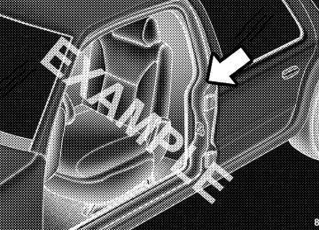
To attach a child restraint tether strap:
• If necessary, move the seat forward to provide better
39
access to the tether anchor.
• Attach the tether strap hook of the child restraint to the tether anchor and remove slack in the tether strap according to the child restraint manufacturer’s instructions.
NOTE: Ensure that the tether strap does not slip into the opening between the seatbacks as you remove slack in the strap.
WARNING!
An incorrectly anchored tether strap could lead to increased head motion and possible injury to the child. Use only the anchor position directly behind the child seat to secure a child restraint top tether strap.
• Route the tether strap to provide the most direct path for the strap between the anchor and the child seat, routing it under the head restraint.
Tether Straps Routed To Tether Anchors
40
Transporting Pets Airbags deploying in the front seat could harm your pet. An unrestrained pet will be thrown about and possibly injured, or could injure a passenger during panic braking or in an accident.
Pets should be restrained in the rear seat in pet harnesses or pet carriers that are secured by seat belts.
ENGINE BREAK-IN RECOMMENDATIONS A long break-in period is not required for the engine and drivetrain (transmission and axle) in your vehicle.
Drive moderately during the first 300 miles (500 km). After the initial 60 miles (100 km), speeds up to 50 or 55 mph (80 or 90 km/h) are desirable.
While cruising, brief full-throttle acceleration within the limits of local traffic laws, contributes to a good break-in. Wide-open throttle acceleration in low gear can be detri- mental and should be avoided.
The engine oil installed in the engine at the factory is a high-quality energy conserving type lubricant. Oil changes should be consistent with anticipated climate conditions under which vehicle operations will occur. For the recommended viscosity and quality grades refer to “Maintenance Procedures” in “Maintaining Your Ve- hicle”. NON-DETERGENT OR STRAIGHT MINERAL OILS MUST NEVER BE USED.
A new engine may consume some oil during its first few thousand miles (kilometers) of operation. This should be considered a normal part of the break-in and not inter- preted as an indication of difficulty.
1
SAFETY TIPS
Transporting Passengers NEVER TRANSPORT PASSENGERS IN THE CARGO AREA.
WARNING! (Continued)
• Be sure everyone in your vehicle is in a seat and
using a seat belt properly.
WARNING!
Exhaust Gas
• Do not leave children or animals inside parked vehicles in hot weather. Interior heat build-up may cause serious injury or death.
• It is extremely dangerous to ride in a cargo area, inside or outside of a vehicle. In a collision, people riding in these areas are more likely to be seri- ously injured or killed.
WARNING!
Exhaust gases can injure or kill. They contain carbon monoxide (CO), which is colorless and odorless. Breathing it can make you unconscious and can eventually poison you. To avoid breathing (CO) follow these safety tips:
• Do not allow people to ride in any area of your vehicle that is not equipped with seats and seat belts.
Do not run the engine in a closed garage or in confined areas any longer than needed to move your vehicle in or out of the area.
If it is necessary to sit in a parked vehicle with the engine running, adjust your heating or cooling controls to force outside air into the vehicle. Set the blower at high speed.
If you are required to drive with the trunk/liftgate open, make sure that all windows are closed and the climate control BLOWER switch is set at high speed. DO NOT use the recirculation mode.
The best protection against carbon monoxide entry into the vehicle body is a properly maintained engine exhaust system.
Whenever a change is noticed in the sound of the exhaust system, when exhaust fumes can be detected inside the vehicle, or when the underside or rear of the vehicle is damaged, have a competent mechanic inspect the com- plete exhaust system and adjacent body areas for broken, damaged, deteriorated, or mispositioned parts. Open seams or loose connections could permit exhaust fumes to seep into the passenger compartment. In addition,
inspect the exhaust system each time the vehicle is raised for lubrication or oil change. Replace as required. Safety Checks You Should Make Inside The Vehicle
Seat Belts Inspect the belt system periodically, checking for cuts, frays, and loose parts. Damaged parts must be replaced immediately. Do not disassemble or modify the system.
Front seat belt assemblies must be replaced after a collision. Rear seat belt assemblies must be replaced after a collision if they have been damaged (i.e., bent retractor, torn webbing, etc.). If there is any question regarding belt or retractor condition, replace the belt.
Airbag Warning Light The light should come on and remain on for four to eight seconds as a bulb check when the ignition switch is first turned ON. If the light is not lit during starting, see your
authorized dealer. If the light stays on, flickers, or comes on while driving, have the system checked by an autho- rized dealer.
Defroster Check operation by selecting the defrost mode and place the blower control on high speed. You should be able to feel the air directed against the windshield. See your authorized dealer is inoperable.
for service if your defroster
Floor Mat Safety Information Always use floor mats designed to fit the foot well of your vehicle. Use only floor mats that leave the pedal area unobstructed and that are firmly secured so that they cannot slip out of position and interfere with the pedals or impair safe operation of your vehicle in other ways.
WARNING!
Pedals that cannot move freely can cause loss of vehicle control and increase the risk of serious per- sonal injury. • Always make sure that floor mats are properly
attached to the floor mat fasteners.
• Never place or install floor mats or other floor coverings in the vehicle that cannot be properly secured to prevent them from moving and inter- fering with the pedals or the ability to control the vehicle.
• Never put floor mats or other floor coverings on top of already installed floor mats. Additional floor mats and other coverings will reduce the size of the pedal area and interfere with the pedals.
(Continued)
WARNING! (Continued)
• Check mounting of mats on a regular basis. Al- ways properly reinstall and secure floor mats that have been removed for cleaning.
• Always make sure that objects cannot fall into the driver foot well while the vehicle is moving. Objects can become trapped under the brake pedal and accelerator pedal causing a loss of vehicle control.
• If required, mounting posts must be properly
installed, if not equipped from the factory. Failure to properly follow floor mat installation or mounting can cause interference with the brake pedal and accelerator pedal operation causing loss of control of the vehicle.
Periodic Safety Checks You Should Make Outside The Vehicle
Tires Examine tires for excessive tread wear and uneven wear patterns. Check for stones, nails, glass, or other objects lodged in the tread. Inspect the tread and sidewall for cuts and cracks. Check the wheel nuts for tightness. Check the tires (including spare) for proper pressure.
Lights Have someone observe the operation of exterior lights while you work the controls. Check turn signal and high beam indicator lights on the instrument panel.
Door Latches Check for positive closing, latching, and locking.
Fluid Leaks Check area under vehicle after overnight parking for fuel, engine coolant, oil, or other fluid leaks. Also, if gasoline fumes are detected or if fuel, power steering fluid, or brake fluid leaks are suspected, the cause should be located and corrected immediately.
MIRRORS
Inside Day/Night Mirror The mirror can be adjusted up, down, left, and right for various drivers. The mirror should be adjusted to center on the view through the rear window.
Headlight glare from vehicles behind you can be reduced by moving the small control under the mirror to the night position (toward the rear of the vehicle). The mirror should be adjusted while set in the day position (toward the windshield).
Adjusting Rearview Mirror
Automatic Dimming Mirror — If Equipped This mirror automatically adjusts for headlight glare from vehicles behind you. You can turn the feature on or off by pressing the button at the base of the mirror. A light to the left of the button will illuminate to indicate when the dimming feature is activated. The sensor to the right of the button does not illuminate.
Automatic Dimming Mirror
CAUTION!
To avoid damage to the mirror during cleaning, never spray any cleaning solution directly onto the mirror. Apply the solution onto a clean cloth and wipe the mirror clean.
Power Mirrors The power mirror controls are located on the driver’s door trim panel.
Power Mirror Switches
The power mirror controls consist of mirror select switch and a four-way mirror control switch. To adjust a mirror, press the mirror select switch to either the L (left) or R (right) to select the mirror you need to adjust.
Using the mirror control switch, press on any of the four arrows for the direction that you want the mirror to move.
WARNING!
Vehicles and other objects seen in the passenger side convex mirror will look smaller and farther away than they really are. Relying too much on your passenger side mirror could cause you to collide with another vehicle or other object. Use your inside mirror when judging the size or distance of a vehicle seen in the passenger side convex mirror.
Spotter Mirror — If Equipped Some models are equipped with a driver’s side spotter mirror. The spotter mirror allows for a greater range of visibility on the drivers side of the vehicle.
Folding Mirrors
The exterior mirrors are hinged to allow the mirror to pivot forward or rearward to help avoid damage. The mirror has three detent positions: full forward, normal and full rearward. Heated Mirrors
These mirrors are heated to melt frost or ice. This feature is activated whenever you turn on the rear window defroster. Refer to “Rear Window Features” in “Understanding The Features Of Your Vehicle” for fur- ther information.
Spotter Mirror
Sun Visors The driver and passenger sun visors are located on the headliner, near the front windshield. The sun visor can be rotated downward or up against the door glass.
Courtesy Mirrors The passenger side sun visor comes equipped with a courtesy mirror.
Sun Visor (Driver’s Side)
HANDS-FREE PHONE — IF EQUIPPED
Overview Windows Mobile™-based Fiat Blue&Me™ is a personal telematic system enabling to use communication and entertainment applications expressly designed for use in the car.
The Blue&Me™ system installed on your car is equipped with hands-free kit, message reader and media player, and it is preset for future installation of additional services.
The Blue&Me™ system, fully integral with voice com- mands, buttons on the steering wheel and multifunction display messages, gives you the possibility of interacting with your Bluetooth威 wireless technology mobile phone (even if you keep it in your pocket or bag) without having to take your eyes off the road or removing your hands from the steering wheel. To use voice commands you are not required to train the voice recognition system
to recognize your voice. This implies that the system is nearly equally performing with different persons, i.e.: the voice recognition system is of the “speaker independent” type.
With this system you can also play your favorite music stored on USB device and select tracks and playback modes with both voice commands or buttons on the steering wheel.
This device complies with Part 15 of the FCC rules subject to the following two conditions:
• This device may not cause harmful interference.
• This device must accept all
interference received, including interference that may cause undesired operation.
The Hands-Free Kit The basic characteristic of this hands-free kit is voice recognition with Bluetooth威 wireless technology. With this system you can make and receive calls safely and securely using either voice commands or buttons on the steering wheel under whatever driving condition with- out having to take your eyes off the road or removing your hands from the steering wheel, as required by current law regulations.
Bluetooth威 wireless technology enables wireless connec- tion between your mobile phone and the hands-free kit installed on your car.
To use the hands-free kit, you need a Bluetooth威 wireless technology enabled mobile phone. This hands-free kit gives you the possibility of interacting vocally with your mobile phone while driving, even if your mobile device does not feature this capability. You can also interact with
your mobile phone manually and visually using the steering wheel controls and the instrument panel multi- function display.
1 — Mute/ESC 4 — Windows Icon/VR
2 — Phone/Main 3 — Phone Hang Up
3
For further details on the mobile phones supported by Blue&Me™, refer to section Blue&Me™ SUPPORTED MOBILE PHONES.
list or directly pronouncing the phone number, to answer a call and also to answer another incoming phone call.
To get started with Blue&Me™ hands-free kit with voice recognition, you have to simply pair your Bluetooth威 wireless technology enabled mobile phone with the sys- tem.
Pairing is an operation that has to be made only once.
NOTE: • During
the mobile phone pairing procedure, Blue&Me™ attempts to detect a phone equipped with Bluetooth威 wireless technology within range and then establishes the connection using a Personal Identifica- tion Number (PIN).
• Once your phone is paired, you have the option to transfer your mobile phone contacts to the hands-free kit, to make a phone call either by using the contacts
• To interact with Blue&Me™ you can use either buttons on the steering wheel and voice commands. With voice recognition, you can perform system function by speaking voice commands, also identified as “key- words”. When the system recognizes a keyword, it will respond with the appropriate action. Voice recog- nition is an easy and convenient way to use Blue™.
the system functions are available within the All Blue&Me™ Main Menu. When the car is not moving, you can scroll through the complete menu using either but- tons on the steering wheel and voice commands. When you are travelling, you can interact with Blue&Me™ using buttons on the steering wheel or voice commands relevant only to phone functions (LAST CALLS and PHONEBOOK ) and media player. To activate settings when travelling you can only use voice commands.
The hands-free kit enables the following operations:
• Contact Calling By Voice — you can call a contact in your mobile phone phonebook using your voice. You can also call a contact in your phonebook by scanning through the entries on the multifunction display. (To use this option you have to transfer your mobile phone contacts to the hands-free kit phonebook).
• Digit Dialing By Voice — you can dial a phone number by pressing the windows icon button (VR button) on the steering wheel and speaking the digits to be dialed.
• To Call The SMS Text Sender — call directly the last SMS text sender or the sender of a message received and stored yet in the Blue&Me™ inbox.
• To Answer A Call — you can answer an incoming call by pressing the MAIN/Phone button on the steering wheel.
• Conference Call — you can call another contact while you are engaged in a phone conversation (with Bluetooth威 phones supporting this option).
• Call Waiting — while engaged in a phone conversa- tion, you can receive notification of another incoming phone call, answer the other incoming phone call, and switch between two ongoing phone conversations. (Call waiting is only supported by a subset of compat- ible mobile phones).
• Refusing Incoming Call Or Ending A Call — you can refuse an incoming call or end a current call by pressing the Phone Hang-up button on the steering wheel.
After you place your mobile phone in the car environ- ment and create a pairing relationship with Blue&Me™, you can make phone calls by speaking keywords or pressing buttons on the steering wheel. When using the
hands-free phone, the audio output of a phone conver- sation is heard through your car sound speakers.
Message Reader The Blue&Me™ message reader enables automatic read- ing, through the car sound system, of the SMS texts you receive on your Bluetooth威 wireless technology mobile phone that are received when the phone is paired and connected to Blue&Me™ system. It does not provide access to messages that were received before you entered the car and connected with the Blue&Me™ system. The message reader will also interpret any abbreviation and emoticon contained in the SMS text.
NOTE: Not all mobile phones support the SMS text message reader function or automatic phonebook trans- fer via Bluetooth威. Consult www.ciafiat.com for further information on the list of compatible mobile phones.
Message reader functions are managed by the control buttons on the steering wheel or by the Blue&Me™ voice commands.
The Blue&Me™ message reader enables the following operations:
• To display on the instrument panel multifunction display a visual notification signal indicating that you have received a new SMS text on your Bluetooth威 wireless technology mobile phone, with sender’s number/name; Blue&Me™ will also ask whether to read you the message that has been received.
• To manage the list of SMS texts received on your
Blue&Me™ paired mobile phone.
• To read the messages received and stored. Messages
can be read multiple times.
• To call the SMS text sender using the buttons on the
steering wheel or voice commands.
• To delete individual messages or the entire inbox using the buttons on the steering wheel or voice commands.
The Blue&Me™ system can also recognize and read abbreviations, if any (e.g. “ILUVU” will be read like “I love you”) and interpret the most usual emoticons (e.g. :-) will be read like “Smile”), adopted nowadays to write SMS texts.
Media Player With the Blue&Me™ media player you can play, via the car sound system, the digital audio files stored on a USB device by simply connecting it to the USB port located in the glove box of the car.
In this way, while you are driving you can play your favorite personal music collections.
• iPod威 Player — see dedicated paragraph under Media
The media player enables the following operations:
• Digital Audio Playback — you can play all your digital audio files (.mp3,.wma,.wav,.aac) or play a customized playlist (.m3u or.wpl format).
• Audio File Selection By Category — you can play all audio files of a certain category, e.g.: album, artist or genre.
• Playback Options — while playing tracks you can select the following options: Play, Stop, Next track, Previous track, Shuffle and Loop track.
NOTE: • The media player does not support audio files com- pressed with other formats and DRM (Digital Right Management) protected audio files. Non-supported audio files that may be present on the USB device will be ignored.
Player Functions.
• To use the media player, you have to simply connect (directly or by an extension lead) your USB device to the car USB port. Turning the ignition key to ON, Blue&Me™ will start building your media library. At the end of this operation you can surf the whole library and scroll its categories as required using the buttons on the steering wheel or voice commands. Blue&Me™ will then play your selection via the car sound system.
WARNING!
• Operating certain parts of this system while driv- ing can distract your attention away from the road, and possibly cause an accident or other serious consequences; for this reason certain functions shall be disabled by the Blue&Me™ system until driving conditions are secure and, if required, only when the car is stopped.
(Continued)
WARNING! (Continued)
• Read and Follow Instructions: before using your system, read and follow all instructions and safety information provided in this end user manual (“User’s Guide”). Not following precautions found in this User’s Guide can lead to an accident or other serious consequences.
• Keep User’s Guide in the car: when kept in the car, the User’s Guide will be a ready reference for you and other users unfamiliar with the system. Please make certain that before using the system for the first time, all persons have access to the User’s Guide and read its instructions and safety infor- mation carefully.
SEATS Seats are a part of the Occupant Restraint System of the vehicle.
WARNING!
• It is dangerous to ride in a cargo area, inside or outside of a vehicle. In a collision, people riding in these areas are more likely to be seriously injured or killed.
• Do not allow people to ride in any area of your vehicle that is not equipped with seats and seat belts. In a collision, people riding in these areas are more likely to be seriously injured or killed. • Be sure everyone in your vehicle is in a seat and
using a seat belt properly.
Front Seats Forward/Rearward Adjustment The adjusting bar is located at the front of the seats, near the floor.
WARNING!
• Adjusting a seat while driving may be dangerous. Moving a seat while driving could result in loss of control which could cause a collision and serious injury or death.
• Seats should be adjusted before fastening the seat belts and while the vehicle is parked. Serious injury or death could result from a poorly adjusted seat belt.
Recline Adjustment The recline adjustment lever is located on the inboard side of the seat. To recline the seatback, lift up the recline lever, lean back until the desired position has been reached, and release the lever.
Adjusting Bar
While sitting in the seat, lift up on the bar and move the seat forward or rearward. Release the bar once the desired position is reached. Then, using body pressure, move forward and rearward on the seat to be sure that the seat adjusters have latched.
Recline Lever
WARNING!
Do not ride with the seatback reclined so that the shoulder belt is no longer resting against your chest. In a collision you could slide under the seat belt, which could result in serious injury or death.
Seat Height Adjustment The driver’s seat height can be raised or lowered by using a lever, located on the outboard side of the seat. Pump the lever upward to raise the seat height, or pump the lever downward to lower the seat height.
EZ Entry Feature The driver and front passenger seats have an EZ entry feature for rear seat passengers. Pull forward on the release lever, located on the outboard side of the seatback, dump the seatback forward, then slide the seat forward to allow access in and out of the rear seat.
Height Adjuster
EZ Entry Lever
Lift the seatback upright and push the seat rearward to its locked position once the rear passengers are seated.
Memory Feature The drivers seat also has a memory feature. After using the EZ entry function, the seatback and the adjuster will re-lock into the position it was originally adjusted to. Head Restraints Head restraints are designed to reduce the risk of injury by restricting head movement in the event of a rear impact. Head restraints should be adjusted so that the top of the head restraint is located above the top of your ear.
WARNING!
The head restraints for all occupants must be properly adjusted before operating the vehicle or occupying a seat. Head restraints should never be adjusted while the vehicle is in motion. Driving a vehicle with the head restraints improperly adjusted or removed could cause serious injury or death in the event of an accident.
Active Head Restraints — Front Seats The front driver and passenger seats are equipped with Active Head Restraints (AHR). In the event of a rear impact the AHRs will automatically extend forward minimizing the gap between the back of the occupant’s head and the AHR.
To raise the head restraint, pull upward on the head restraint. To lower the head restraint, press the push button, located at the base of the head restraint, and push downward on the head restraint.
NOTE: The head restraints should only be removed by qualified technicians, for service purposes only. If either of the head restraints require removal, see your autho- rized dealer.
WARNING!
Do not place items over the top of the Active Head Restraint, such as coats, seat covers or portable DVD players. These items may interfere with the operation of the Active Head Restraint in the event of a collision and could result in serious injury or death.
Rear Head Restraints To raise the head restraint, pull upward on the head restraint. To lower the head restraint, press the push button, located at the base of the head restraint, and push downward on the head restraint. Refer to “Occupant Restraints” in “Things To Know Before Starting Your Vehicle” for information on tether routing.
Push Button
The AHRs will automatically return to their normal position following a rear impact. If the AHRs do not return to their normal position, see your authorized dealer immediately.
Rear Head Restraint
TO OPEN AND CLOSE THE HOOD To open the hood, two latches must be released.
1. Pull the bottom of the RED hood release lever, located on the left kick panel, rearward.
Safety Latch Location
Lift the hood prop rod that clips to the right side (left side when standing in front of the hood) of the engine compartment. Place the hood prop rod in the hole of hood hinge to secure the hood in the open position.
Hood Release Lever
2. Rotate the safety catch under the front edge of the hood, near the center, and raise the hood.
In hot climates, the prop rod may be hot. Pick up the prop rod at the foam on the end of the prop rod.
WARNING!
Be sure the hood is fully latched before driving your vehicle. If the hood is not fully latched, it could open when the vehicle is in motion and block your vision. Failure to follow this warning could result in serious injury or death.
CAUTION!
To prevent possible damage, do not slam the hood to close it. Lower the hood until it is open approxi- mately 8 in (20 cm) and then drop it. This should secure both latches. Never drive your vehicle unless the hood is fully closed, with both latches engaged.
LIGHTS
Multifunction Lever The multifunction lever, located on the left side of the steering wheel, controls the operation of the headlights, headlight beam selection, passing light and turn signals.
NOTE: The external lights can only be turned on with the ignition in the ON/RUN position. Headlights
Rotate the end of the multifunction lever up- ward to the first detent for headlight operation.
Headlight Operation
NOTE: When the headlights are turned on, the Daytime Running Lights will be deactivated.
High Beams
With the low beams activated, push the multifunc- tion lever towards the instrument panel to turn on the high beams. Pull the multifunction lever toward the steering wheel to turn off the high beams. Flash-To-Pass You can signal another vehicle with your headlights by lightly pulling the multifunction lever toward the steer- ing wheel. This will turn on the high beams until the lever is released. Parking Lights
To turn on the parking lights, remove the key or turn the ignition to OFF/LOCK position and turn on the headlights.
Daytime Running Lights — If Equipped To activate the Daytime Running Lights (DRL), rotate the end of the multifunction lever to the O symbol.
NOTE: The low beams and side/taillights will not be on with DRL.
The DRL function can be turned on or off using the display menus. Refer to “Electronic Vehicle Information Center (EVIC)” in “Understanding Your Instrument Panel” for further information. Turn Signals Push the multifunction lever upward to signal a right turn or downward to signal a left turn. The correspond- ing indicator in the instrument cluster will blink to indicate the operation of the turn signal.
3
Lane Change Assist Tap the lever up or down once, without moving beyond the detent, and the turn signal (right or left) will flash three times then automatically turn off. Follow Me Home/Headlight Delay When this feature is selected the driver can choose to have the headlights remain on for a preset period of time.
Activation Remove the key or turn the ignition to the OFF/LOCK position, and pull the multifunction lever toward the steering wheel, within two minutes. Each time the lever is pulled, the activation of the lights will be extended by 30 seconds. The activation of the lights can be extended to a maximum of 210 seconds.
Deactivation Pull the multifunction lever toward the steering wheel and hold it for more than two seconds.
Turn Signal Operation
NOTE: The indicators will automatically turn off when the turn has been completed and the steering wheel is returned to a straight position.
Interior Lights The map/reading light can be set to three different positions:
Interior Light Timing (Center Position) There are three different modes of operation that can be activated in this position:
• Press the switch to the right; the light is always on
• When one door is opened, a three minute timer is
• Press the switch to the left; the light is always off
• Center position, or neutral; the lights are turned on
and off when the doors are opened or closed.
NOTE: On some models only the drivers door will turn the interior lights on and off.
CAUTION!
Before getting out of the vehicle be sure that the switch is in the center position or that the lights are off. Make sure that the interior lights are off when the doors are closed to avoid draining the battery.
activated.
• When the key is removed from the ignition (within two minutes of being turned off), a 10 second timer is activated.
• When the doors are unlocked (either with the Key Fob or with the key in the driver’s door), a 10 second timer is activated.
Interior Light Timing (Off Position) There are two modes of operation in this position:
• When all doors are closed, a three minute timer is
activated.
NOTE: The timer is deactivated when the key is moved into the ON/RUN position.
• When the doors are locked (either with the Key Fob or with the key in the driver’s door), the lights will turn off.
Front Fog Lights — If Equipped The fog light switch is located on the center stack of the instrument panel, just below the radio.
Fog Light Switch
Press the switch once to turn the front fog lights on. Press the switch a second time to turn the front fog lights off.
WINDSHIELD WIPERS AND WASHERS The windshield wiper/washer lever is located on the right side of the steering column.
NOTE: The windshield wipers/washers will only oper- ate with the ignition in the ON/RUN position. Front Windshield Wiper Operation There are five different modes of operation for the front windshield wipers. The windshield wiper lever can be raised or lowered to access these modes:
Windshield Wiper Operation
CAUTION!
• Turn the windshield wipers off when driving through an automatic car wash. Damage to the windshield wipers may result if the wiper control is left in any position other than off.
• In cold weather, always turn off the wiper switch and allow the wipers to return to the “Park” position before turning off the engine. If the wiper switch is left on and the wipers freeze to the windshield, damage to the wiper motor may occur when the vehicle is restarted.
• Always remove any buildup of snow that prevents the windshield wiper blades from returning to the off position. If the windshield wiper control is turned off and the blades cannot return to the off position, damage to the wiper motor may occur.
Windshield Wiper Off This is the normal position of the wiper lever.
Intermittent Wiper Operation Push the lever downward to the first detent. The wipers will operate intermittently.
NOTE: The Intermittent function only has one detent but wiper delay will vary with changes in vehicle speed. As vehicle speed increases the delay time will decrease.
Low Speed Push the lever downward to the second detent. The wipers will operate at low speed.
High Speed Push the lever downward to the third detent. The wipers will operate at high speed.
Manual High Speed/Mist Push the lever upward from the off position. The wipers will operate at high speed to clear off road mist or spray
REVERSE, the rear wiper will automatically operate at Low Speed and return to normal operation when the transmission is shifted out of REVERSE.
Rear Wiper Operation
NOTE: The windshield wipers/washers will only oper- ate with the ignition in the ON position.
from a passing vehicle. This operation will continue until the lever is released. When the lever is released, the wipers will return to the off position and automatically shut off.
Front Windshield Washer Operation Pull the windshield wiper/washer lever toward the steering wheel to activate the washers and a single wipe of the windshield. Pull and hold the lever for more then a half second and the wipers will activate automatically for three cycles after the lever is released. Rear Windshield Wiper Rotate the end of the windshield wiper/washer lever upward to the first detent past the intermittent settings for intermittent wipe operation. With the front wind- shield wiper active, rotate the end of the windshield wiper/washer lever upward. The rear wiper will operate in the same mode as the front windshield wipers, but at half the frequency. When the transmission is shifted into
Rear Windshield Washer Operation Push the windshield wiper/washer lever toward the instrument panel to activate the rear washer and a single wipe of the rear window. Push and hold the lever for more than a half second and the wipers will activate automatically for three cycles after the lever is released.
TILT STEERING COLUMN — IF EQUIPPED This feature allows you to tilt the steering column upward or downward. The tilt control lever is located on the left-side of the steering column, below the turn signal controls.
Push down on the lever to unlock the column. With one hand firmly on the steering wheel, move the steering column up or down as desired. Push the lever up to lock the column firmly in place.
WARNING!
Do not adjust the steering column while driving. Adjusting the steering column while driving or driv- ing with the steering column unlocked, could cause the driver to lose control of the vehicle. Be sure the steering column is locked before driving your ve- hicle. Failure to follow this warning may result in serious injury or death.
Tilt Control Lever
ELECTRONIC SPEED CONTROL When engaged, the Electronic Speed Control takes over accelerator operations at speeds greater than 25 mph (40 km/h).
The Electronic Speed Control buttons are located on the right side of the steering wheel.
In order to ensure proper operation, the Elec- NOTE: tronic Speed Control system has been designed to shut down if multiple Speed Control functions are operated at the same time. If this occurs, the Electronic Speed Control system can be reactivated by pushing the Electronic Speed Control ON/OFF button and resetting the desired vehicle set speed. To Activate Push the ON/OFF button. The Cruise Indicator light in the instrument cluster will illuminate. To turn the system off, push the ON/OFF button a second time. The Cruise Indicator light will turn off. The system should be turned off when not in use.
Speed Control Buttons
WARNING!
Leaving the Electronic Speed Control system on when not in use is dangerous. You could accidentally set the system or cause it to go faster than you want. You could lose control and have an accident. Always leave the system OFF when you are not using it.
To Set A Desired Speed Turn the Electronic Speed Control ON. When the vehicle has reached the desired speed, press the SET (-) button and release. Release the accelerator and the vehicle will operate at the selected speed.
NOTE: The vehicle should be traveling at a steady speed and on level ground before pressing the SET button.
To Deactivate A soft tap on the brake pedal, pushing the CANC button, or normal brake pressure while slowing the vehicle will deactivate Electronic Speed Control without erasing the set speed memory. Pressing the ON/OFF button or turning the ignition switch OFF erases the set speed memory. To Resume Speed To resume a previously set speed, push the RES (+) button and release. Resume can be used at any speed above 20 mph (32 km/h). To Vary The Speed Setting When the Electronic Speed Control is set, you can in- crease speed by pushing the RES (+) button. If the button is continually pressed, the set speed will continue to increase until the button is released, then the new set speed will be established.
3
Pressing the RES (+) button once will result in a 1 mph (2 km/h) increase in set speed. Each subsequent tap of the button results in an increase of 1 mph (2 km/h).
Using Electronic Speed Control On Hills The transmission may downshift on hills to maintain the vehicle set speed.
To decrease speed while the Electronic Speed Control is set, push the SET (-) button. If the button is continually held in the SET (-) position, the set speed will continue to decrease until the button is released. Release the button when the desired speed is reached, and the new set speed will be established.
Pressing the SET (-) button once will result in a 1 mph (2 km/h) decrease in set speed. Each subsequent tap of the button results in a decrease of 1 mph (2 km/h). To Accelerate For Passing Press the accelerator as you would normally. When the pedal is released, the vehicle will return to the set speed.
NOTE: The Electronic Speed Control system maintains speed up and down hills. A slight speed change on moderate hills is normal.
On steep hills, a greater speed loss or gain may occur so it may be preferable to drive without Electronic Speed Control.
WARNING!
Electronic Speed Control can be dangerous where the system cannot maintain a constant speed. Your ve- hicle could go too fast for the conditions, and you could lose control and have an accident. Do not use Electronic Speed Control in heavy traffic or on roads that are winding, icy, snow-covered or slippery.
REAR PARK ASSIST — IF EQUIPPED The Rear Park Assist system provides an audible indica- tion of the distance between the rear fascia/bumper and a detected obstacle when backing up, e.g. during a parking maneuver. Refer to the “Park Assist System Usage Precautions” for the limitations of this system and recommendations.
Rear Park Assist is automatically activated when the transmission is placed into REVERSE. As the distance from an obstacle behind the vehicle decreases, the au- dible alert becomes more frequent. Rear Park Assist Sensors The four Rear Park Assist sensors, located in the rear fascia/bumper, monitor the area behind the vehicle that is within the sensors’ field of view. The sensors can detect obstacles, in the horizontal direction, from approximately 12 in (30 cm) up to 55 in (140 cm) from the center of the rear fascia/bumper and up to 24 in (60 cm) from the
corners of the rear fascia/bumper, depending on the location, type and orientation of the obstacle.
If several obstacles are detected, the rear park assist system indicates the nearest obstacle.
The minimum height of a detectable obstacle corre- sponds to the maximum height of an obstacle that would clear the underside of the car during the parking maneuver. Rear Park Assist Alerts If an obstacle is behind the vehicle when REVERSE gear is engaged, an audible alert is activated.
The tones emitted by the loudspeaker inform the driver that the vehicle is approaching an obstacle. The pauses between the tones are directly proportional to the dis- tance from the obstacle. Pulses emitted in quick succes- sion indicate the presence of a very close obstacle. A continuous tone indicates that the obstacle is less than 12 in (30 cm) away.
Audible And Visual Signals Supplied By The Rear Park Assist System.
SIGNAL
MEANING
INDICATION
Obstacle Distance
An obstacle is present within the
system field of view
Failure
Sensor or System failures
Audible signal (dashboard loud- speaker) • Sound pulses emitted at a rate that increase as the distance de- creases. • Emits continuous tone at 12 in (30 cm) • Adjustable volume level. (Refer to “Menu Functions” for further infor- mation). Visual Signal (instrument panel) • Icon appears on display. • Message is displayed on multi- function display (where provided).
While audible signals are emitted, the audio system is not muted.
The audible signal is cut out immediately if the distance increases. The tone cycle remains constant if the distance measured by the inner sensors is constant. If this condi- tion occurs for the external sensors, the signal is cut off after 3 seconds (stopping warnings during maneuvers parallel to walls). Failure Indications A malfunction of the Rear Park Assist sensors or system is indicated, during REVERSE gear engagement, by the instrument panel warning icon.
The warning icon is illuminated and a message is displayed on the multifunction display (if equipped). Refer to “Instrument Cluster De- scriptions” in “Understanding Your Instrument
Panel” for further information.
The sensors and wiring are tested continuously when the ignition is in the ON/RUN position. Failures are indi- cated immediately if they occur when the system is ON.
Even if the system is able to identify that a specific sensor is in failure condition, the instrument cluster display shall indicate that the rear park assist system is unavail- able, without reference to the sensor in failure condition. If even a single sensor fails, the entire system must be disabled. The system is turned off automatically. Cleaning The Rear Park Assist System Clean the Rear Park Assist sensors with water, car wash soap and a soft cloth. Do not use rough or hard cloths. In washing stations, clean sensors quickly keeping the va- por jet/high pressure washing nozzles at least 4 in (10 cm) from the sensors. Do not scratch or poke the sensors. Otherwise, you could damage the sensors.
Park Assist System Usage Precautions
NOTE: • Ensure that the rear bumper is free of snow, ice, mud, dirt and debris to keep the Rear Park Assist system operating properly.
• Jackhammers, large trucks, and other vibrations could
affect the performance of Rear Park Assist.
• Clean the Rear Park Assist sensors regularly, taking care not to scratch or damage them. The sensors must not be covered with ice, snow, slush, mud, dirt or debris. Failure to do so can result in the system not working properly. The Rear Park Assist system might not detect an obstacle behind the fascia/bumper, or it could provide a false indication that an obstacle is behind the fascia/bumper.
• Objects such as bicycle carriers, etc., must not be placed within 12 in (30 cm) from the rear fascia/
bumper while driving the vehicle. Failure to do so can result in the system misinterpreting a close object as a sensor problem, causing a failure indication to be displayed in the instrument cluster.
CAUTION!
• Rear Park Assist is only a parking aid and it is unable to recognize every obstacle, including small obstacles. Parking curbs might be temporar- ily detected or not detected at all. Obstacles lo- cated above or below the sensors will not be detected when they are in close proximity.
• The vehicle must be driven slowly when using Rear Park Assist in order to be able to stop in time when an obstacle is detected. It is recommended that the driver looks over his/her shoulder when using Rear Park Assist.
WARNING!
WARNING! (Continued)
• Drivers must be careful when backing up even when using the Rear Park Assist system. Always check carefully behind your vehicle, look behind you, and be sure to check for pedestrians, animals, other vehicles, obstructions, and blind spots be- fore backing up. You are responsible for safety and must continue to pay attention to your surround- ings. Failure to do so can result in serious injury or death.
(Continued)
• Before using the Rear Park Assist System, it is strongly recommended that the ball mount and hitch ball assembly is disconnected from the ve- hicle when the vehicle is not used for towing. Failure to do so can result in injury or damage to vehicles or obstacles because the hitch ball will be much closer to the obstacle than the rear fascia when the warning display turns on the single flashing arc and sounds the continuous tone. Also, the sensors could detect the ball mount and hitch ball assembly, depending on its size and shape, giving a false indication that an obstacle is behind the vehicle.
POWER SUNROOF — IF EQUIPPED The power sunroof roof switch is located in the overhead console.
Power Sunroof Switch
WARNING!
• Never leave children in a vehicle with the key in the ignition switch. Occupants, particularly unat- tended children, can become entrapped by the power sunroof while operating the power sunroof switch. Such entrapment may result in serious injury or death.
• In a collision, there is a greater risk of being thrown from a vehicle with an open sunroof. You could also be seriously injured or killed. Always fasten your seat belt properly and make sure all passengers are properly secured too.
• Do not allow small children to operate the sun- roof. Never allow your fingers, other body parts, or any object to project through the sunroof opening. Injury may result.
To Open Press the power sunroof switch rearward and the sunroof will stop at the vented position. Press the switch a second time and release and the sunroof will open fully, then stop automatically. This is called “Express Open”. During Express Open operation, any movement of the sunroof switch will stop the sunroof. To Close With the sunroof in the full open position, press the sunroof button and the sunroof will return to the vented position. Press the switch a second time to completely close the sunroof. Pinch Protect Override If a known obstruction (ice, debris, etc.) prevents the sunroof from closing, press the switch forward and hold for two seconds after the reversal occurs. This allows the sunroof to move toward the closed position.
NOTE: Pinch protection is disabled while the switch is pressed. Wind Buffeting Wind buffeting can be described as the perception of pressure on the ears or a helicopter-type sound in the ears. Your vehicle may exhibit wind buffeting with the windows down, or the sunroof (if equipped) in certain open or partially open positions. This is a normal occur- rence and can be minimized. If the buffeting occurs with the rear windows open, open the front and rear windows together to minimize the buffeting. If the buffeting occurs with the sunroof open, adjust the sunroof opening to minimize the buffeting or open any window.
Sun Shade — If Equipped For vehicles equipped with either a power sunroof or a fixed glass roof, there is a sun shade that can be open or closed. To open the sun shade press the tab and move the shade to a full open position.
Manual Sun Shade
ELECTRICAL POWER OUTLETS There is a standard 12 Volt (13 Amp) power outlet, located in the floor console, for added convenience. This power outlet can power mobile phones, electronics and other low power devices.
Power is available when the ignition switch is in the ON/RUN or START position. Insert the cigar lighter or accessory plug into the outlet for use. To preserve the heating element, do not hold the lighter in the heating position.
CAUTION!
• Do not exceed the maximum power of 160 Watts (13 Amps) at 12 Volts. If the 160 Watt (13 Amp) power rating is exceeded, the fuse protecting the system will need to be replaced.
• Power outlets are designed for accessory plugs only. Do not insert any other object in the power outlets as this will damage the outlet and blow the fuse. Improper use of the power outlet can cause damage not covered by your warranty.
WARNING!
To avoid serious injury or death: • Only devices designed for use in this type of outlet should be inserted into any 12 Volt outlet.
• Do not touch with wet hands. • Close the lid when not in use and while driving
the vehicle.
• If this outlet is mishandled, it may cause an
electric shock and failure.
Power Outlet
Power Outlet Fuse Location Underhood
F15 Fuse 15 A Blue Cigar Lighter Front Console
3
CAUTION!
• Many accessories that can be plugged in draw power from the vehicle’s battery, even when not in use (i.e., cellular phones, etc.). Eventually, if plugged in long enough, the vehicle’s battery will discharge sufficiently to degrade battery life and/or prevent the engine from starting.
• Accessories that draw higher power (i.e., coolers, vacuum cleaners, lights, etc.) will degrade the battery even more quickly. Only use these inter- mittently and with great caution.
• After the use of high power draw accessories, or long periods of the vehicle not being started (with accessories still plugged in), the vehicle must be driven a sufficient length of time to allow the generator to recharge the vehicle’s battery.
CIGAR LIGHTER — IF EQUIPPED
WARNING!
When the cigar lighter is in use it becomes very hot. To avoid serious injury, handle the cigar lighter with care. Always check that the cigar lighter has turned off.
CUPHOLDERS For the driver and front passenger, cupholders are lo- cated on the floor console between the front seats.
For rear passengers, there are cupholders located on the floor between the front driver and passenger seats.
Front Cupholders
Rear Cupholders
STORAGE
Glove Box Compartment The glove box is located on the right side of the instru- ment panel. Pull outward on the door latch to open the glove box. Push the glove box door upward to close it.
Passenger Seat Storage — If Equipped Some models may be equipped with storage under the front passenger seat. Pull outward on the latch to open the storage compartment.
Glove Box Compartment
Passenger Seat Storage
CARGO AREA FEATURES The rear seatbacks have a fold down feature to allow increased cargo capacity.
Push down the release button, located at the outboard top of the seatback and move the seatback to its folded- down position to provide a flat load floor cargo area. When returning the seatback to its upright position, push rearward until the seatback is properly latched.
Rear Seat Release Buttons
Folded Rear Seats
1
CAUTION! (Continued)
• Use care when washing the inside of the rear window. Do not use abrasive window cleaners on the interior surface of the window. Use a soft cloth and a mild washing solution, wiping parallel to the heating elements. Labels can be peeled off after soaking with warm water.
• Do not use scrapers, sharp instruments, or abra- sive window cleaners on the interior surface of the window.
• Keep all objects a safe distance from the window.
REAR WINDOW FEATURES
Rear Window Defroster
The rear window defroster button is located in the center of the instrument panel, below the radio. Press this button to turn on the rear window defroster. An indicator in the button will illuminate when the rear window defroster is on. The rear window defroster automatically turns off after approximately 20 minutes. To manually shut the defroster off, push the button a second time.
NOTE: To prevent excessive battery drain, use the rear window defroster only when the engine is operating.
CAUTION!
Failure to follow these cautions can cause damage to the heating elements:
(Continued)
INSTRUMENT PANEL FEATURES
1 — Side Vent 2 — Multifunction Lever – Light Control 3 — Instrument Cluster And Warning Lights 4 — Windshield Wiper, Washer, Trip Computer 10 — Hazard Button 5 — Central Air Vents 6 — Storage Compartment/Radio
7 — Passenger Air Bag 8 — Glove Compartment 9 — Rear Defrost Button
11 — Climate Controls/Storage Compartment 12 — Power Windows Control
13 — Storage Compartment 14 — Shift Lever 15 — Sport Button 16 — Horn/Driver Airbag
INSTRUMENT CLUSTER
INSTRUMENT CLUSTER DESCRIPTIONS
2. Rear Defrost Button
1. Glow Plug Light — If Equipped
The Glow Plug light will flash during engine oil viscosity sensor measurement in cold weather. During this measurement (up to 10 seconds), the starter will be disabled. If the measured oil viscosity is OK, the light will go out and the engine will be allowed to crank. If the measured oil viscosity is too high, engine cranking will be disabled and the light will blink repeatedly until the oil temperature is raised, preferably by an externally- powered electric engine block heater (available from your authorized dealer).
The message ⬙Plug In Engine Heater⬙, will be displayed in the instrument cluster when the ambient temperature is below 5°F (-15°C) at the time the engine is shut off as a reminder to avoid possible crank delays at the next cold start.
Press and release this button to turn on the rear window defroster. This indicator will illuminate when the rear window defroster is on. The rear window defroster automatically turns off after 10 minutes.
CAUTION!
Failure to follow these cautions can cause damage to the heating elements: • Use care when washing the inside of the rear window. Do not use abrasive window cleaners on the interior surface of the window. Use a soft cloth and a mild washing solution, wiping parallel to the heating elements. Labels can be peeled off after soaking with warm water.
• Do not use scrapers, sharp instruments, or abra- sive window cleaners on the interior surface of the window.
(Continued)
CAUTION! (Continued)
• Keep all objects a safe distance from the window.
3. Front Fog Light Indicator — If Equipped
This indicator will illuminate when the front fog lights are on.
4. Low Fuel Light
When the fuel level reaches approximately 1.0 gal- lon (3.8L) this light will turn on, and remain on until fuel is added.
5. High Beam Indicator
This light indicates that the headlights are on high beam. Pull the turn signal lever toward the steer-
ing wheel to switch the headlights to low beam.
6. Position Light Indicator / Follow Me Home (Headlight Delay) Indicator — If Equipped
This indicator will illuminate when the park lights or headlights are turned on. If the Follow Me Home feature is activated this indicator will illuminate and the EVIC will show how long the function remains active. For further information, refer to “Follow Me Home” in “Understanding The Features of Your Vehicle”.
7. Turn Signal Indicators
The arrows will flash in unison with the exterior turn signal, when using the turn signal lever.
8. Generic Warning Light
The Generic Warning Light will illuminate if any of the following conditions occur: Engine Oil Pressure Sensor Failure, External Light Fail- ure, Fuel Cut-Off Intervention, Fuel Cut-Off
Not Available, Parking Sensor Failure.
9. Airbag Warning Light
This light will turn on for four seconds as a bulb check when the ignition switch is first turned to ON/RUN. If the light is either not on during starting, stays on, or turns on while driving, then have the system inspected at an authorized dealer as soon as possible. Refer to “Occupant Restraints” in “Things To Know Before Starting Your Vehicle” for further information.
10. Cruise Indicator — If Equipped
This indicator shows that the Speed Control system is ON.
11. Seat Belt Reminder Light
When the ignition switch is first turned to ON/ RUN, this light will turn on if the driver’s seat belt is unbuckled, a chime will sound. When driving, if the driver’s seat belt remains unbuckled, the Seat Belt
Reminder Light will illuminate and the chime will sound. Refer to “Occupant Restraints” in “Things To Know Before Starting Your Vehicle” for further information.
12. Charging System Light
This light shows the status of the electrical charg- ing system. The light should come on when the ignition switch is first turned to ON/RUN and remain on briefly as a bulb check. If the light stays on or comes on while driving, turn off some of the vehicle’s non-essential electrical devices or increase engine speed (if at idle). If the charging system light remains on, it means that the vehicle is experiencing a problem with the charging system. Obtain SERVICE IMMEDIATELY. See an autho- rized dealer.
If jump starting is required, refer to “Jump Starting Procedures” in “What To Do In Emergencies”.
13. Power Steering System Warning
This light is used to manage the electrical warning of the EPS (Power Steering System). Refer to “Power Steering” in “Starting and Operating” for further information.
14. Electronic Throttle Control (ETC) Light
This light informs you of a problem with the Electronic Throttle Control (ETC) system. If a problem is detected, the light will come on while the engine is running. Cycle the ignition key when the vehicle has completely stopped and the shift lever is placed in the NEUTRAL position. The light should turn off. If the light remains lit with the engine running, your vehicle will usually be drivable; however, see an authorized dealer for service as soon as possible. If the light is flashing when the engine is running, imme- diate service is required and you may experience reduced performance, an elevated/rough idle or engine stall and your vehicle may require towing. The light will come on
when the ignition is first turned to ON/RUN and remain on briefly as a bulb check. If the light does not come on during starting, have the system checked by an autho- rized dealer.
15. Tire Pressure Monitoring Telltale Light
Each tire, including the spare (if provided), should be checked monthly, when cold and inflated to the inflation pressure recommended by the vehicle manufacturer on the vehicle placard or tire inflation pressure label. (If your vehicle has tires of a different size than the size indicated on the vehicle placard or tire inflation pressure label, you should determine the proper tire inflation pressure for those tires.)
As an added safety feature, your vehicle has been equipped with a Tire Pressure Monitoring System (TPMS) that illuminates a low tire pressure telltale when one or more of your tires is significantly under-inflated.
5
illuminated. This sequence will continue upon subse- quent vehicle start-ups as long as the malfunction exists. When the malfunction indicator is illuminated, the sys- tem may not be able to detect or signal low tire pressure as intended. TPMS malfunctions may occur for a variety of reasons, including the installation of replacement or alternate tires or wheels on the vehicle that prevent the TPMS from functioning properly. Always check the TPMS malfunction telltale after replacing one or more tires or wheels on your vehicle, to ensure that the replacement or alternate tires and wheels allow the TPMS to continue to function properly.
Accordingly, when the low tire pressure telltale illumi- nates, you should stop and check your tires as soon as possible, and inflate them to the proper pressure. Driving on a significantly under-inflated tire causes the tire to overheat and can lead to tire failure. Under-inflation also reduces fuel efficiency and tire tread life, and may affect the vehicle’s handling and stopping ability.
Please note that the TPMS is not a substitute for proper tire maintenance, and it is the driver’s responsibility to maintain correct tire pressure, even if under-inflation has not reached the level to trigger illumination of the TPMS low tire pressure telltale.
Your vehicle has also been equipped with a TPMS malfunction indicator to indicate when the system is not operating properly. The TPMS malfunction indicator is combined with the low tire pressure telltale. When the system detects a malfunction, the telltale will flash for approximately one minute and then remain continuously
CAUTION!
The TPMS has been optimized for the original equipment tires and wheels. TPMS pressures and warning have been established for the tire size equipped on your vehicle. Undesirable system opera- tion or sensor damage may result when using re- placement equipment that is not of the same size, type, and/or style. Aftermarket wheels can cause sensor damage. Do not use tire sealant from a can, or balance beads if your vehicle is equipped with a TPMS, as damage to the sensors may result.
16. Automatic Gearbox Failure
This light will automatic transmission fault.
illuminate when there is an
17. Oil Pressure Warning Light
This light indicates low engine oil pressure. The light should turn on momentarily when the engine is started. If the light turns on while driving, stop the vehicle and shut off the engine as soon as possible. A chime will sound for four minutes when this light turns on.
Do not operate the vehicle until the cause is corrected. This light does not indicate how much oil is in the engine. The engine oil level must be checked under the hood.
18. Malfunction Indicator Light (MIL)
The Malfunction Indicator Light (MIL) is part of an onboard diagnostic system, called OBD, that monitors engine and automatic transmission con- trol systems. The light will illuminate when the key is in the ON/RUN position, before engine start. If the bulb does not come on when turning the key from OFF/LOCK to ON/RUN, have the condition checked promptly.
Certain conditions such as a loose or missing gas cap, poor fuel quality, etc., may illuminate the MIL after engine start. The vehicle should be serviced if the light stays on through several of your typical driving cycles. In most situations, the vehicle will drive normally and will not require towing.
CAUTION!
Prolonged driving with the MIL on could cause damage to the engine control system. It also could affect fuel economy and drivability. If the MIL is flashing, severe catalytic converter damage and power loss will soon occur. Immediate service is required.
WARNING!
A malfunctioning catalytic converter, as referenced above, can reach higher temperatures than in normal operating conditions. This can cause a fire if you drive slowly or park over flammable substances such as dry plants or wood or cardboard, etc. This could result in death or serious injury to the driver, occu- pants or others.
19. Engine Temperature Warning Light
This light warns of an overheated engine condi- tion. The engine coolant temperature indicator will illuminate and a single chime will sound after
reaching a set threshold.
If the light turns on while driving, safely pull over and stop the vehicle. If the A/C system is on, turn it off. Also, shift the transmission into NEUTRAL and idle the ve- hicle. If the temperature reading does not return to
normal, turn the engine off immediately and call for service. Refer to “If Your Engine Overheats” in “What To Do In Emergencies” for further information.
20. Brake Warning Light
This light monitors various brake functions, including brake fluid level and parking brake application. If the brake light turns on, it may indicate that the parking brake is applied, that the brake fluid level is low, or that there is a problem with the brake system reservoir.
If the light remains on when the parking brake has been disengaged, and the fluid level is at the full mark on the master cylinder reservoir, it indicates a possible brake hydraulic system malfunction or that a problem with the Brake Booster has been detected by the Anti-Lock Brake System (ABS) / Electronic Stability Control (ESC) system. In this case, the light will remain on until the condition has been corrected. If the problem is related to the brake
booster, the ABS pump will run when applying the brake and a brake pedal pulsation may be felt during each stop.
The dual brake system provides a reserve braking capac- ity in the event of a failure to a portion of the hydraulic system. A leak in either half of the dual brake system is indicated by the Brake Warning Light, which will turn on when the brake fluid level in the master cylinder has dropped below a specified level.
The light will remain on until the cause is corrected.
If brake failure is indicated, immediate repair is neces- sary.
WARNING!
Driving a vehicle with the red brake light on is dangerous. Part of the brake system may have failed. It will take longer to stop the vehicle. You could have a collision. Have the vehicle checked immediately.
Vehicles equipped with the Anti-Lock Brake System (ABS), are also equipped with Electronic Brake Force Distribution (EBD). In the event of an EBD failure, the Brake Warning Light will turn on along with the ABS Light. Immediate repair to the ABS system is required.
Operation of the Brake Warning Light can be checked by turning the ignition switch from the OFF/LOCK position to the ON/RUN position. The light should illuminate for approximately two seconds. The light should then turn off unless the parking brake is applied or a brake fault is detected. If the light does not illuminate, have the light inspected by an authorized dealer.
The light also will turn on when the parking brake is applied with the ignition switch in the ON/RUN posi- tion.
NOTE: This light shows only that the parking brake is applied. It does not show the degree of brake application.
21. Electronic Stability Control (ESC) OFF Indicator Light — If Equipped
This light indicates the Electronic Stability Con- trol system (ESC) has been turned off by the driver.
22. Electronic Stability Control (ESC) Activation / Malfunction Indicator Light — If Equipped
The “ESC Activation/Malfunction Indicator Light” in the instrument cluster will come on for four seconds when the ignition switch is turned to the ON/RUN position. If the “ESC Activation/Malfunction Indicator Light” comes on con- tinuously with the engine running, a malfunction has been detected in the ESC system. If this light remains on, see your authorized dealer as soon as possible to have the problem diagnosed and corrected.
10
NOTE: • The “ESC Off
Indicator Light” and the “ESC Activation/Malfunction Indicator Light” come on mo- mentarily each time the ignition switch is turned to ON/RUN.
If the ABS light is on, the brake system should be serviced as soon as possible to restore the benefits of Anti-Lock brakes. If the ABS light does not turn on when the ignition switch is turned to the ON/RUN position, have the light inspected by an authorized dealer.
• Each time the ignition is turned to ON/RUN, the ESC system will be ON even if it was turned off previously.
23. Anti-Lock Brake (ABS) Light
This light monitors the Anti-Lock Brake System (ABS). The light will turn on when the ignition switch is turned to the ON/RUN position and may stay on for as long as four seconds.
If the ABS light remains on or turns on while driving, it indicates that the Anti-Lock portion of the brake system is not functioning and that service is required. However, the conventional brake system will continue to operate normally if the BRAKE warning light is not on.
24. Door Ajar
This light will turn on to indicate that one or more door or the trunk may be ajar.
25. Vehicle Security Light — If Equipped
This light will flash at a fast rate for approxi- mately 15 seconds, when the vehicle security alarm is arming, and then will flash slowly until the vehicle is disarmed.
26. Temperature Gauge The temperature digital scale shows engine coolant tem- perature. Any reading within the normal range indicates that the engine cooling system is operating satisfactorily.
The gauge pointer will likely indicate a higher tempera- ture when driving in hot weather, up mountain grades, or when towing a trailer. It should not be allowed to exceed the upper limits of the normal operating range.
CAUTION!
Driving with a hot engine cooling system could damage your vehicle. If all the segments of tempera- ture gauge are lit pull over and stop the vehicle. Idle the vehicle with the air conditioner turned off until the pointer drops back into the normal range. If you hear continuous chimes, turn the engine off immedi- ately, and call an authorized dealership for service.
11
WARNING!
A hot engine cooling system is dangerous. You or others could be badly burned by steam or boiling coolant. You may want to call an authorized dealer- ship for service if your vehicle overheats. If you decide to look under the hood yourself, see “Main- taining Your Vehicle”. Follow the warnings under the Cooling System Pressure Cap paragraph.
27. Odometer / Trip Odometer / Electronic Vehicle Information Center (EVIC) Display Area This display indicates the total distance the vehicle has been driven.
NOTE: • U.S. Federal regulations require that upon transfer of vehicle ownership, the seller certify to the purchaser the correct mileage that the vehicle has been driven. If your odometer needs to be repaired or serviced, the repair
12
technician should leave the odometer reading the same as it was before the repair or service. If s/he cannot do so, then the odometer must be set at zero, and a sticker must be placed in the door jamb stating what the mileage was before the repair or service. It is a good idea for you to make a record of the odometer reading before the repair/service, so that you can be sure that it is properly reset, or that the door jamb sticker is accurate if the odometer must be reset at zero.
• If the vehicle is equipped with the optional Electronic Vehicle Information Center (EVIC) in the instrument cluster, all warnings including “door” and “gate” and “Change Engine Oil” will only be displayed in the EVIC display. For additional information, refer to “Electronic Vehicle Information Center (EVIC) — If Equipped”.
When the appropriate conditions exist, this display shows the EVIC messages.
Refer to the Electronic Vehicle Information Center (EVIC) for further information.
28. Fuel Gauge / Fuel Door Reminder The fuel door reminder indicates that the fuel filler door is located on the right side of the vehicle. When the ignition switch is in the ON/RUN position, the digital scale will show the level of fuel remaining in the fuel tank.
NOTE: The fuel gauge and range will not immediately update accurately when refueling with the engine on.
29. Tachometer The white area of the scale shows the permissible engine revolutions-per-minute (RPM x 1000) for each gear range. Before reaching the red area, ease up on the accelerator to prevent engine damage.
30. Speedometer The Speedometer shows the vehicle speed in miles per hour and/or kilometers per hour (mph/kph).
ELECTRONIC VEHICLE INFORMATION CENTER (EVIC) The Electronic Vehicle Information Center (EVIC) fea- tures a driver-interactive display that is located in the instrument cluster.
Electronic Vehicle Information Center (EVIC) Display
The EVIC consists of the following:
• System Status
• Vehicle Information Warning Message Displays
• Personal Settings (Customer-Programmable Features)
• Outside Temperature Display
• Trip Computer Functions EVIC Control Buttons Press the MENU ESC button briefly to access the menu and/or go to next screen or to confirm the required menu option. Press and hold the MENU ESC button (approxi- mately one seconds) to return to the main screen.
Press the + button to scroll upward through the dis- played menu and the related options or to increase the displayed value.
Press the – button to scroll downward through the displayed menu and the related options or to decrease the value displayed.
NOTE: Buttons + and – activate different functions according to the following situations:
• To scroll the menu options upwards and downwards;
The setup menu can be activated by pressing the MENU ESC button. Single presses on buttons + or – will scroll through the setup menu options. The menu includes the following functions:
• To increase or decrease values during settings.
NOTE: When opening one of the front doors, the EVIC display will turn on for a few seconds the clock and the km or mi covered (for versions/markets, where provided). Electronic Vehicle Information Center (EVIC) Setup Menu The menu comprises a series of functions arranged in a cycle which can be selected by pressing the + and – buttons to access the different options and settings (setup).
• Speed Beep
• Trip B Data
• Set Time
• Set Date
• See Radio
• Speed Display
• Autoclose
• Units
• Language
• Buzzer Volume
• Button Volume
• Hill Start
• Daylights (D.R.L.)
• Exit Menu
Selecting An Option Of The Main Menu Without Submenu:
• Briefly press the MENU ESC button to select the main
menu option to set;
Selecting An Option Of The Main Menu With Submenu:
• Briefly press the MENU ESC button to display the first
submenu option;
• Press the + or – button (by single presses) to scroll all
the submenu options;
• Briefly press the MENU ESC button to select the displayed submenu option and to open the relevant setup menu;
• Press the + or – button (by single presses) to select the
• Press the + or – button (by single presses) to select the
new setting;
new setting for this submenu option;
• Briefly press the MENU ESC button to store the new setting and go back to the main menu option previ- ously selected.
• Briefly press the MENU ESC button to store the new setting and to go back to the previously selected submenu option.
• Press and hold the MENU ESC button to return to the main menu (short hold) or the main screen (longer hold).
release the MENU/ESC button. To reset the oil change indicator system (after performing the scheduled main- tenance) refer to the following procedure.
Change Engine Oil Indicator System
Change Engine Oil Your vehicle is equipped with an engine oil change indicator system. The “Change Engine Oil” message will flash in the EVIC display for approximately 10 seconds after a single chime has sounded, to indicate the next scheduled oil change interval. The engine oil change indicator system is duty cycle based, which means the engine oil change interval may fluctuate, dependent upon your personal driving style.
Unless reset, this message will continue to display each time you turn the ignition switch to the ON/RUN position. To turn off the message temporarily, press and
1. Turn the ignition switch to the ON position (Do not start the engine).
2. Fully depress the accelerator pedal, slowly, three times