- 2000 Nissan Sentra Owners Manuals
- Nissan Sentra Owners Manuals
- 1999 Nissan Sentra Owners Manuals
- Nissan Sentra Owners Manuals
- 2010 Nissan Sentra Owners Manuals
- Nissan Sentra Owners Manuals
- 2003 Nissan Sentra Owners Manuals
- Nissan Sentra Owners Manuals
- 2009 Nissan Sentra Owners Manuals
- Nissan Sentra Owners Manuals
- 1996 Nissan Sentra Owners Manuals
- Nissan Sentra Owners Manuals
- 1998 Nissan Sentra Owners Manuals
- Nissan Sentra Owners Manuals
- 2006 Nissan Sentra Owners Manuals
- Nissan Sentra Owners Manuals
- 2002 Nissan Sentra Owners Manuals
- Nissan Sentra Owners Manuals
- 1997 Nissan Sentra Owners Manuals
- Nissan Sentra Owners Manuals
- 2005 Nissan Sentra Owners Manuals
- Nissan Sentra Owners Manuals
- 2011 Nissan Sentra Owners Manuals
- Nissan Sentra Owners Manuals
- 2001 Nissan Sentra Owners Manuals
- Nissan Sentra Owners Manuals
- 2007 Nissan Sentra Owners Manuals
- Nissan Sentra Owners Manuals
- 2012 Nissan Sentra Owners Manuals
- Nissan Sentra Owners Manuals
- 2008 Nissan Sentra Owners Manuals
- Nissan Sentra Owners Manuals
- 2004 Nissan Sentra Owners Manuals
- Nissan Sentra Owners Manuals
- Download PDF Manual
-
The front passenger air bag is designed to automatically turn OFF under some con- ditions. Read this section carefully to learn how it operates. Proper use of the seat, seat belt and child restraints is nec- essary for most effective protection. Fail- ure to follow all instructions in this manual concerning the use of seats, seat belts and child restraints can increase the risk or severity of injury in an accident.
The front passenger air bag status light or is located near the climate controls. After the ignition switch is placed in the ⬙ON⬙ position, the front passenger air bag status light on the instrument panel illuminates for about 7
seconds and then turns off or operates depend- ing on the front passenger seat occupied status. The light operates as follows:● Unoccupied passenger’s seat: The
or bag is OFF and will not inflate in a crash.
is OFF and the front passenger air
1-52 Safety—Seats, seat belts and supplemental restraint system
weight. It works together with seat belt sensors described later. For example, if a child is in the front passenger seat, the Advanced Air Bag Sys- tem is designed to turn the passenger air bag OFF in accordance with the regulations. Also, if a child restraint of the type specified in the regula- tions is on the seat, its weight and the child’s weight can be detected and cause the air bag to turn OFF. Occupant classification sensor opera- tion can vary depending on the front passenger seat belt sensors. The front passenger seat belt sensors are de- signed to detect if the seat belt is buckled and the amount of tension on the seat belt, such as when it is in the Automatic Locking Retractor (ALR) mode (child restraint mode). Based on the weight on the seat detected by the occupant classification sensor and the belt tension de- tected on the seat belt, the Advanced Air Bag System determines whether the front passenger air bag should be automatically turned OFF as required by the regulations. Front passenger seat adult occupants who are properly seated and using the seat belt as out- lined in this manual should not cause the passen- ger air bag to be automatically turned OFF. For small adults it may be turned OFF, however if the occupant takes his/her weight off the seat cush- ion (for example, by not sitting upright, by sitting on an edge of the seat, or by otherwise being out
In addition,
of position), this could cause the sensor to turn the air bag OFF. if the occupant improperly uses the seat belt in the ALR mode (child restraint mode), this could cause the air bag to be turned OFF. Always be sure to be seated and wearing the seat belt properly for the most effective protection by the seat belt and supplemental air bag. NISSAN recommends that pre-teens and chil- dren be properly restrained in a rear seat. NISSAN also recommends that appropriate child restraints and booster seats be properly installed in a rear seat. If this is not possible, the occupant classification sensor and seat belt sensors are designed to operate as described above to turn the front passenger air bag OFF for specified child restraints as required by the regulations. Failing to properly secure child restraints and to use the ALR mode (child restraint mode) may allow the restraint to tip or move in an accident or sudden stop. This can also result in the passen- ger air bag inflating in a crash instead of being OFF. See “Child restraints” earlier in this section for proper use and installation. If the front passenger seat is not occupied the passenger air bag is designed not to inflate in a crash. However, heavy objects placed on the seat could result in air bag inflation, because of the object’s weight detected by the occupant classification sensor. Other conditions could also
result in air bag inflation, such as if a child is standing on the seat, or if two children are on the seat, contrary to the instructions in this manual. Always be sure that you and all vehicle occupants are seated and restrained properly. Using the passenger air bag status light, you can monitor when the front passenger air bag is au- tomatically turned OFF with the seat occupied. The light will not illuminate when the front pas- senger seat is unoccupied. If an adult occupant is in the seat but the passen- ger air bag status light is illuminated (indicating that the air bag is OFF), it could be that the person is a small adult, or is not sitting on the seat properly or not using the seat belt properly. If a child restraint must be used in the front seat, the passenger air bag status light may or may not be illuminated, depending on the size of the child and the type of child restraint being used. If the air bag status light is not illuminated (indicating that the air bag might inflate in a crash), it could be that the child restraint or seat belt is not being used properly. Make sure that the child restraint is installed properly, the seat belt is used properly and the occupant is positioned properly. If the air bag status light is not illuminated, reposition the occupant or child restraint in a rear seat.
Safety—Seats, seat belts and supplemental restraint system 1-53
If the passenger air bag status light will not illu- minate even though you believe that the child restraint, the seat belts and the occupant are properly positioned, the system may be sensing an unoccupied seat (in which case the air bag is OFF). Your NISSAN dealer can check that the system is OFF by using a special tool. However, until you have confirmed with your dealer that your air bag is working properly, reposition the occupant or child restraint in a rear seat. The air bag system and passenger air bag status light will take a few seconds to register a change in the passenger seat status. For example, if a large adult who is sitting in the front passenger seat exits the vehicle, the passenger air bag status light will go from OFF to ON for a few seconds and then to OFF. This is normal system operation and does not indicate a malfunction. If a malfunction occurs in the front passenger air bag system, the supplemental air bag warning , located in the meter and gauges area light in the center of the instrument panel, will blink. Have the system checked by a NISSAN dealer.
Other supplemental front-impact air bag precautions
WARNING
● Do not place any objects on the steer- ing wheel pad or on the instrument panel. Also, do not place any objects between any occupant and the steering wheel or instrument panel. Such ob- jects may become dangerous projec- tiles and cause injury if the front air bags inflate.
● Immediately after
inflation, several front air bag system components will be hot. Do not touch them; you may se- verely burn yourself.
● No unauthorized changes should be made to any components or wiring of the supplemental air bag system. This is to prevent accidental inflation of the supplemental air bag or damage to the supplemental air bag system.
● Do not make unauthorized changes to your vehicle’s electrical system, sus- pension system or front end structure. This could affect proper operation of the front air bag system.
● Tampering with the front air bag system may result in serious personal injury. Tampering includes changes to the steering wheel and the instrument panel assembly by placing material over the steering wheel pad and above the instrument panel or by installing additional trim material around the air bag system.
● Modifying or tampering with the front passenger seat may result in serious personal injury. For example, do not change the front seats by placing mate- rial on the seat cushion or by installing additional trim material, such as seat covers, on the seat that are not specifi- cally designed to assure proper air bag operation. Additionally, do not stow any objects under the front passenger seat or the seat cushion and seatback. Such objects may interfere with the proper operation of the occupant classifica- tion sensor (pressure sensor).
● No unauthorized changes should be made to any components or wiring of the seat belt system. This may affect the front air bag system. Tampering with the seat belt system may result in seri- ous personal injury.
1-54 Safety—Seats, seat belts and supplemental restraint system
● Work on and around the front air bag system should be done by a NISSAN dealer. Installation of electrical equip- ment should also be done by a NISSAN dealer. The Supplemental Restraint System (SRS) wiring should not be modified or disconnected. Unauthor- ized electrical test equipment and prob- ing devices should not be used on the air bag system.
● A cracked windshield should be re- placed immediately by a qualified re- pair facility. A cracked windshield could affect the function of the supplemental air bag system.
*The SRS wiring harness connectors are yellow and orange for easy identification. When selling your vehicle, we request that you inform the buyer about the supplemental front air bag system and guide the buyer to the appropri- ate sections in this Owner’s Manual.
inflate if the forces in another type of collision are similar to those of a higher severity side impact. They are designed to inflate on the side where the vehicle is impacted. They may not inflate in cer- tain side collisions.
LRS0259
Vehicle damage (or lack of it) is not always an indication of proper side air bag and curtain air bag operation. When the side air bags and curtain air bags inflate, a fairly loud noise may be heard, followed by release of smoke. This smoke is not harmful and does not indicate a fire. Care should be taken not to inhale it, as it may cause irritation and choking. Those with a history of a breathing con- dition should get fresh air promptly. Side air bags, along with the use of seat belts, help to cushion the impact force on the chest of the front occupants. Curtain air bags help to cushion the impact force to the head of occu- pants in the front and rear outboard seating po- sitions. They can help save lives and reduce serious injuries. However, an inflating side air bag and curtain air bag may cause abrasions or other injuries. Side air bags and curtain air bags do not provide restraint to the lower body. The seat belts should be correctly worn and the driver and passenger seated upright as far as practical away from the side air bag. Rear seat passengers should be seated as far away as Safety—Seats, seat belts and supplemental restraint system 1-55
Front seat-mounted side-impact supplemental air bag and roof- mounted curtain side-impact supplemental air bag systems The side air bags are located in the outside of the seatback of the front seats. The curtain air bags are located in the side roof rails. These systems are designed to meet voluntary guidelines to help reduce the risk of injury to out-of-position occu- pants. However, all of the information, cau- tions and warnings in this manual still ap- ply and must be followed. The side air bags and curtain air bags are designed to inflate in higher severity side collisions, although they may
practical from the door finishers and side roof rails. The side air bags and curtain air bags inflate quickly in order to help protect the front and rear outboard occupants. Because of this, the force of the side air bag and curtain air bag inflating can increase the risk of injury if the occupant is too close to, or is against, these air bag modules during inflation. The side air bags and curtain air bags will deflate quickly after the collision is over. The side air bags and curtain air bags op- erate only when the ignition switch is in the ON or START position.
After placing the ignition switch in the ON position, the supplemental air bag warning light illuminates. The supplemental air bag warning light will turn off after about 7
seconds if the system is operational.WARNING
● Do not place any objects near the seat- back of the front seats. Also, do not place any objects (an umbrella, bag, etc.) between the front door finisher and the front seat. Such objects may become dangerous projectiles and cause injury if a side air bag inflates.
● Right after inflation, several side air bag and curtain air bag system components will be hot. Do not touch them; you may severely burn yourself.
● No unauthorized changes should be made to any components or wiring of the side air bag and curtain air bag systems. This is to prevent damage to or accidental inflation of the side air bag and curtain air bag or damage to the side air bag and curtain air bag systems. ● Do not make unauthorized changes to your vehicle’s electrical system, sus- pension system or side panel. This could affect proper operation of the side air bag and curtain air bag systems. ● Tampering with the side air bag system may result in serious personal injury. For example, do not change the front seats by placing material near the seat- backs or by installing additional trim material, such as seat covers, around the side air bag.
● Work around and on the side air bag and curtain air bag systems should be done by a NISSAN dealer. Installation of electrical equipment should also be done by a NISSAN dealer. The SRS wir- ing harnesses* should not be modified or disconnected. Unauthorized electri- cal test equipment and probing devices should not be used on the side air bag system.
* The SRS wiring harness connectors are yellow and orange for easy identification.
When selling your vehicle, we request that you inform the buyer about the side air bag and curtain air bag systems and guide the buyer to the appropriate sections in this Owner’s Manual. Seat belts with pretensioners (front seats)
WARNING
● The pretensioners cannot be reused af- ter activation. They must be replaced together with the retractor and buckle as a unit.
1-56 Safety—Seats, seat belts and supplemental restraint system
● If the vehicle becomes involved in a collision but a pretensioner is not acti- vated, be sure to have the pretensioner system checked and, if necessary, re- placed by your NISSAN dealer.
● No unauthorized changes should be made to any components or wiring of the pretensioner system. This is to pre- vent damage to or accidental activation of the pretensioners. Tampering with the pretensioner system may result in serious personal injury.
● Work around and on the pretensioner system should be done by a NISSAN dealer. Installation of electrical equip- ment should also be done by a NISSAN dealer. Unauthorized electrical test equipment and probing devices should not be used on the pretensioner system. ● If you need to dispose of a pretensioner or scrap the vehicle, contact a NISSAN dealer. Incorrect disposal procedures could cause personal injury.
Working with the seat belt retractor, the preten- sioner helps tighten the seat belt when the ve- hicle becomes involved in certain types of colli- sions, helping to restrain front seat occupants.
The pretensioner is encased within the seat belt retractor. These seat belts are used the same way as conventional seat belts. When a pretensioner activates, smoke is re- leased and a loud noise may be heard. This smoke is not harmful and does not indicate a fire. Care should be taken not to inhale it, as it may cause irritation and choking. Those with a history of a breathing condition should get fresh air promptly. After pretensioner activation, load limiters allow the seat belt to release webbing (if necessary) to reduce forces against the chest.
is The supplemental air bag warning light used to indicate malfunctions in the pretensioner (See ⬙SUPPLEMENTAL AIR BAG system. WARNING LIGHT⬙ in this section for more de- tails.) If the operation of the supplemental air bag warning light indicates there is a malfunction, have the system checked by a NISSAN dealer. When selling your vehicle, we request that you inform the buyer about the pretensioner system and guide the buyer to the appropriate sections in this Owner’s Manual.
WRS0897
SRS Front Air Bag Warning Labels
1. SUPPLEMENTAL AIR BAG WARNING LABELS Warning labels about the supplemental front- impact air bag system are placed in the vehicle as shown in the illustration.
Safety—Seats, seat belts and supplemental restraint system 1-57
Repair and replacement procedure The front air bags, side air bags, curtain air bags and pretensioners are designed to inflate on a one-time-only basis. As a reminder, unless it is damaged, the supplemental air bag warning light remains illuminated after inflation has occurred. Repair and replacement of these supplemental air bag systems should be done only by a NISSAN dealer. When maintenance work is required on the ve- hicle, the front air bags, side air bags, curtain air bags, pretensioners and related parts should be pointed out to the person performing the mainte- nance. The ignition switch should always be placed in the LOCK position when working under the hood or inside the vehicle.
If any of the following conditions occur, the front air bag, side air bag, curtain air bag and preten- sioner systems need servicing: ● The supplemental air bag warning light re-
mains on after approximately 7 seconds.
● The supplemental air bag warning light
flashes intermittently.
● The supplemental air bag warning light does
not come on at all.
Under these conditions, the front air bag, side air bag, curtain air bag or pretensioner systems may not operate properly. They must be checked and repaired. Take your vehicle to the nearest NISSAN dealer.
WARNING
If the supplemental air bag warning light is on, it could mean that the front air bag, side air bag, curtain air bag and/or preten- sioner systems will not operate in an ac- cident. To help avoid injury to yourself or others, have your vehicle checked by a NISSAN dealer as soon as possible.
LRS0100
SUPPLEMENTAL AIR BAG WARNING LIGHT air bag warning light, The supplemental displaying in the instrument panel, moni- tors the circuits for the air bag systems, preten- sioners and all related wiring. When the ignition switch is placed in the ON or START position, the supplemental air bag warn- ing light illuminates for about 7 seconds and then turns off. This means the system is operational.
1-58 Safety—Seats, seat belts and supplemental restraint system
WARNING
● Once a front air bag, side air bag, or curtain air bag has inflated, the air bag module will not function again and must be replaced. Additionally, the ac- tivated pretensioner must also be re- placed. The air bag module and preten- sioner should be replaced by a NISSAN dealer. The air bag module and preten- sioner cannot be repaired.
● The front air bag, side air bag, curtain air bag systems and the pretensioner system should be inspected by a NISSAN dealer if there is any damage to the front end or side portion of the vehicle.
● If you need to dispose of the supple- mental air bag or pretensioner systems or scrap the vehicle, contact a NISSAN dealer. Incorrect disposal procedures could cause personal injury.
Safety—Seats, seat belts and supplemental restraint system 1-59
2 Instruments and controls
Instrument panel. . . . . . . . . . . . . . . . . . . . . . . . . . . . . . . . . . . 2-2
Meters and gauges . . . . . . . . . . . . . . . . . . . . . . . . . . . . . . . . 2-3
Speedometer and odometer . . . . . . . . . . . . . . . . . . . . . 2-4
Tachometer . . . . . . . . . . . . . . . . . . . . . . . . . . . . . . . . . . . . 2-6
g (gravity)-force gauge (if so equipped) . . . . . . . . . . . 2-6
Engine coolant temperature gauge . . . . . . . . . . . . . . . 2-6
Fuel gauge . . . . . . . . . . . . . . . . . . . . . . . . . . . . . . . . . . . . 2-7
Engine oil pressure gauge (if so equipped) . . . . . . . . 2-8
Trip computer (if so equipped) . . . . . . . . . . . . . . . . . . . 2-8
Outside temperature display (if so equipped) . . . . . . 2-9
Warning/indicator lights and audible reminders . . . . . . 2-10
Checking bulbs . . . . . . . . . . . . . . . . . . . . . . . . . . . . . . . 2-11
Warning lights . . . . . . . . . . . . . . . . . . . . . . . . . . . . . . . . 2-11
Indicator lights . . . . . . . . . . . . . . . . . . . . . . . . . . . . . . . . 2-15
Audible reminders . . . . . . . . . . . . . . . . . . . . . . . . . . . . . 2-18
Security systems . . . . . . . . . . . . . . . . . . . . . . . . . . . . . . . . . 2-18
Vehicle security system (if so equipped). . . . . . . . . . 2-18
NISSAN vehicle immobilizer system . . . . . . . . . . . . . 2-20
Windshield wiper and washer switch . . . . . . . . . . . . . . . 2-21
Switch operation . . . . . . . . . . . . . . . . . . . . . . . . . . . . . . 2-21Rear window and outside mirror (if so equipped) defroster switch . . . . . . . . . . . . . . . . . . . . . . . . . . . . . . . . . . 2-22
Headlight and turn signal switch. . . . . . . . . . . . . . . . . . . . 2-23Headlight control switch. . . . . . . . . . . . . . . . . . . . . . . . 2-23
Daytime running light system (Canada only) . . . . . . 2-24
Instrument brightness control . . . . . . . . . . . . . . . . . . . 2-24
Turn signal switch . . . . . . . . . . . . . . . . . . . . . . . . . . . . . 2-25
Fog light switch (if so equipped) . . . . . . . . . . . . . . . . 2-25
Hazard warning flasher switch . . . . . . . . . . . . . . . . . . . . . 2-25
Horn . . . . . . . . . . . . . . . . . . . . . . . . . . . . . . . . . . . . . . . . . . . . 2-26
Vehicle Dynamic Control (VDC) off switch (if so equipped) . . . . . . . . . . . . . . . . . . . . . . . . . . . . . . . . . . 2-26
Heated seat (if so equipped). . . . . . . . . . . . . . . . . . . . . . . 2-27
Power outlet . . . . . . . . . . . . . . . . . . . . . . . . . . . . . . . . . . . . . 2-27
Storage . . . . . . . . . . . . . . . . . . . . . . . . . . . . . . . . . . . . . . . . . 2-28
Map pockets . . . . . . . . . . . . . . . . . . . . . . . . . . . . . . . . . . 2-28
Storage bin . . . . . . . . . . . . . . . . . . . . . . . . . . . . . . . . . . . 2-29
Storage trays . . . . . . . . . . . . . . . . . . . . . . . . . . . . . . . . . 2-29
Instrument panel storage (if so equipped) . . . . . . . . 2-29
Seatback pockets (if so equipped) . . . . . . . . . . . . . . 2-30
Cup holders . . . . . . . . . . . . . . . . . . . . . . . . . . . . . . . . . . 2-31
Glove box . . . . . . . . . . . . . . . . . . . . . . . . . . . . . . . . . . . . 2-32
Console box . . . . . . . . . . . . . . . . . . . . . . . . . . . . . . . . . . 2-32
Trunk divider (if so equipped) . . . . . . . . . . . . . . . . . . . 2-32
Cargo net (if so equipped). . . . . . . . . . . . . . . . . . . . . . 2-33
Grocery hooks (if so equipped) . . . . . . . . . . . . . . . . . 2-34Windows . . . . . . . . . . . . . . . . . . . . . . . . . . . . . . . . . . . . . . . . 2-35
Power windows (if so equipped) . . . . . . . . . . . . . . . . 2-35
Manual windows (if so equipped). . . . . . . . . . . . . . . . 2-38
Moonroof (if so equipped) . . . . . . . . . . . . . . . . . . . . . . . . . 2-38Electric moonroof. . . . . . . . . . . . . . . . . . . . . . . . . . . . . . 2-38
Interior light . . . . . . . . . . . . . . . . . . . . . . . . . . . . . . . . . . . . . . 2-40
Map lights (if so equipped) . . . . . . . . . . . . . . . . . . . . . . . . 2-41
Trunk light . . . . . . . . . . . . . . . . . . . . . . . . . . . . . . . . . . . . . . . 2-42INSTRUMENT PANEL
7. Windshield wiper/washer switch
(P. 2-21) Storage bin (if so equipped) (P. 2-28) Audio system (P. 4-32, 4-35, 4-39)
8. 9. 10. Center ventilator (P. 4-14) 11. Passenger’s supplemental air bag
(P. 1-43)
12. Side ventilator (P. 4-14) 13. Storage bin (if so equipped) (P. 2-29) 14. Engine oil pressure gauge
(if so equipped) (P. 2-8)
15. g (gravity)-force gauge (if so equipped)
(P. 2-6)
16. Hazard warning flasher switch
(if so equipped) (P. 2-25)
17. Hazard warning flasher switch
(if so equipped) (P. 2-25); Manual shift mode switch (if so equipped) (P.5-15)
18. Navigation system* (if so equipped)
(P. 4-45)
19. Glove box (P. 2-32) 20. Front passenger air bag status light
(P. 1-43)
21. Climate control (P. 4-14) 22. Shift selector (P. 5-13) 23. Power outlet (P. 2-27) Ignition switch (P. 5-7) 24.
1.
2.
Headlight/fog light (if so equipped) /turn signal switch (P. 2-23); Manual shift paddles (if so equipped) (P.5-15) Steering wheel switch for audio control and Bluetooth姞 Hands-Free Phone System (if so equipped) (P. 4-61, 4-63)
3.
Driver’s supplemental air bag/Horn (P. 1-43, 2-26)
4. Meters and gauges (P. 2-3) 5. 6.
Instrument brightness control (P. 2-24) Cruise control main/set switches (if so equipped) (P. 5-21)
2-2 Instruments and controls
WIC1600
METERS AND GAUGES
25. Tilt steering (P.3-27) 26. Storage bin (P. 2-29) 27. Hood release lever (P. 3-23) 28
Vehicle Dynamic Control (VDC) off switch (if so equipped) (P.2-17)
* Refer to the separate Navigation System Own- er’s Manual (if so equipped). See the page number indicated in paren- theses for operating details.
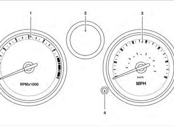
1. 2.
3.
Tachometer Fuel gauge/odometer/transmission po- sition indicator/engine coolant tempera- ture gauge/Instrument brightness level/ trip computer (if so equipped) Speedometer
LIC1014
4.
Instrument brightness control/change button for twin trip odometer/change button for trip computer (if so equipped)
Instruments and controls 2-3
Changing the display: Push the instrument brightness control/change button to change the display as follows: With twin trip odometer: Odometer → Trip A → Trip B → Odometer With trip computer: Odometer → Trip A → Trip B → DTE → Instant Fuel Economy → Average Fuel Consumption → Average Speed → Journey time → Odometer Resetting the trip odometer: Push the instrument brightness control/change button for more than 1 second to reset the cur- rently displayed trip odometer to zero.
LIC1015
WIC1508
SPEEDOMETER AND ODOMETER Speedometer The speedometer indicates the vehicle speed.
Odometer/Twin trip odometer The odometer/twin trip odometer is displayed when the ignition switch is placed in the ON position.
The odometer records the total distance the ve- hicle has been driven.
The twin trip odometer records the distance of individual trips.
To switch between the odometer and the twin trip odometers press the instrument brightness control/change button.
2-4 Instruments and controls
LRS2003
Loose fuel cap warning message Push the reset button 䊊A for more than 1 second to reset the LOOSE FUEL CAP warning mes- sage 䊊B after the fuel cap has been tightened. For additional information see “Fuel-filler cap” in the “Pre-driving checks and adjustments” section of this manual.
LIC2169
Check tire pressure warning message (if so equipped) The CHECK TIRE PRESSURE warning message is displayed when the low tire pressure warning light is illuminated and low tire pressure is de- tected. Check and adjust the tire pressure to the recommended COLD tire pressure shown on the Tire and Loading Information label. The CHECK TIRE PRESSURE warning message turns off when the low tire pressure warning light turns off.The low tire pressure warning light remains illu- minated until the tires are inflated to the recom- mended COLD tire pressure. The CHECK TIRE PRESSURE warning message is displayed each time the ignition switch is placed in the ON position as long as the low tire pressure warning light remains illuminated. For more information see “Low tire pressure warning light” in the “In- struments and controls” section, “Tire Pressure Monitoring System (TPMS)” in the “Starting and driving” and “Wheels and tires” section in the “Maintenance and do-it-yourself” section of this Owner’s Manual.
Instruments and controls 2-5
LIC1021
LIC1113
TACHOMETER The tachometer indicates engine speed in revo- lutions per minute (rpm). Do not rev the engine into the red zone 䊊1 .
g (gravity)-FORCE GAUGE (if so equipped) This gauge shows the straight-line acceleration and deceleration g-forces while you are driving.
CAUTION
When engine speed approaches the red zone, shift to a higher gear or reduce en- gine speed. Operating the engine in the red zone may cause serious engine damage.
NOTE: The g-force gauge does not indicate cor- nering g-forces.
LIC1530
ENGINE COOLANT TEMPERATURE GAUGENOTE:
The ignition switch must be placed in the ON position for the gauge to give a reading.
The gauge indicates the engine coolant tempera- ture. The engine coolant temperature is within the normal range when the reading is within the zone 䊊A shown in the illustration. The engine coolant temperature varies with the outside air temperature and driving conditions.
2-6 Instruments and controls
CAUTION
If the gauge indicates a coolant tempera- ture near the hot (H) end of the normal range, reduce vehicle speed to decrease the temperature. If the gauge is over the normal range, stop the vehicle as soon as safely possible. If the engine is over- heated, continued operation of the ve- hicle may seriously damage the engine. See “If your vehicle overheats” in the “In case of emergency” section for immediate action required
LIC1529
FUEL GAUGE
NOTE: The ignition switch must be placed in the ON position for the gauge to give a reading. The gauge indicates the approximate fuel level in the tank. The gauge may move slightly during braking, turning, acceleration, or going up or down hills. The low fuel warning light comes on when the amount of fuel in the tank is getting low.
Refill the fuel tank before the gauge regis- ters E (Empty).
The located on the passenger’s side of the vehicle.
indicates that the fuel-filler door is
CAUTION
● If
the vehicle runs out of
fuel, Malfunction Indicator Light the (MIL) may come on. Refuel as soon as possible. After a few driving trips, light should turn off. If the the light remains on after a few driving trips, have the vehicle inspected by a NISSAN dealer.
● For additional information, see “Mal- function Indicator Light (MIL)” later in this section.
Instruments and controls 2-7
CAUTION
● This gauge is not designed to indicate low engine oil level. Use the dipstick to check the oil level. (See “Engine oil” in the “Maintenance and do-it-yourself” section.)
● If the gauge needle does not move with the proper amount of engine oil, have the vehicle checked by a NISSAN dealer. Continued vehicle operation in such a condition could cause serious damage to the engine.
TRIP COMPUTER (if so equipped) When the ignition switch is placed in the ON position, modes of the trip computer can be selected by pushing the trip computer change button on the instrument panel located near the speedometer. The following modes can be se- lected in the display: ● Distance to empty ● Instant fuel economy ● Average fuel consumption ● Average speed ● Journey time
Distance to empty (dte—mile or km) The distance to empty (dte) mode provides you with an estimation of the distance that can be driven before refueling. The dte is constantly be- ing calculated, based on the amount of fuel in the fuel tank and the actual fuel consumption.
The display is updated every 30 seconds.
NOTE:
When driving uphill or rounding curves, the fuel in the tank shifts, which may momen- tarily change the display. Instant fuel economy The instant fuel economy mode shows the instant fuel consumption. The display updates instantly when driving. Average fuel consumption (Mpg or l/100km) The average fuel consumption mode shows the average fuel consumption since the last reset. Resetting is done by pressing the change button for more than approximately 1 second. The dis- play is updated every 30 seconds. At about the first 1/3 miles (500 m) after a reset, the display shows (----).
LIC1114
ENGINE OIL PRESSURE GAUGE (if so equipped) The gauge indicates the engine lubrication sys- tem oil pressure while the engine is running. When the engine speed is high, the engine oil pressure is also high. When the engine speed is low, the gauge indicates lower oil pressure.Engine oil pressure also changes based on en- gine temperature. The oil pressure will be higher when the engine is cold and lower when the engine is warm.
2-8 Instruments and controls
Average speed (mph or km/h) The average speed mode shows the average vehicle speed since last reset. Resetting is done by pressing the trip or change button for more than approximately 1 second. The display is up- dated every 30 seconds. The first 30 seconds after a reset, the display shows (----). Journey time The journey time mode shows the time since the last reset. The displayed time can be reset by pressing the change button for more than ap- proximately 1 second. Trip computer reset Pushing the change button for more than 3 sec- onds will reset all modes except Trip A and dis- tance to empty (dte). OUTSIDE TEMPERATURE DISPLAY (if so equipped) The outside temperature function provides a dis- play of the outside temperature when the ignition switch is placed in the ON position. The display of positive temperatures is unsigned (blank), negative temperatures are prefixed with a minus sign.
Instruments and controls 2-9
WARNING/INDICATOR LIGHTS AND AUDIBLE REMINDERS
or
or
Anti-lock Braking System (ABS) warning light
NISSAN Intelligent Key™ warning light (if so equipped)
Malfunction Indicator Light (MIL)
Brake warning light
P position selecting warning light (CVT models) (if so equipped)
Overdrive off indicator light (CVT models)
Charge warning light
Seat belt warning light and chime
Security indicator light
Door open warning light
Supplemental air bag warning light
Side light and headlight indicator light (green)
Electric power steering warning light
Continuously Variable Transmission (CVT) position indicator light (CVT models)
Slip indicator light (if so equipped)
Engine oil pressure warning light
Low fuel warning light
Cruise main switch indicator light (if so equipped)
Cruise set switch indicator light (if so equipped)
Turn signal/hazard indicator lights
Vehicle Dynamic Control (VDC) OFF indicator light (if so equipped)
Low tire pressure warning light (if so equipped)
or
Front passenger air bag status light
Low windshield-washer fluid warning light (if so equipped)
High beam indicator light (blue)
2-10 Instruments and controls
CHECKING BULBS With all doors closed, apply the parking brake and place the ignition switch in the ON position without starting the engine. The following lights will come on:
or
If equipped, the following lights come on briefly and then go off:
or
If any light fails to come on, it may indicate an open circuit in the electrical system. Have the system repaired promptly. WARNING LIGHTS
or
Anti-lock Braking System (ABS) warning light
When the ignition switch is placed in the ON position, the Anti-lock Braking System (ABS) warning light illuminates and then turns off. This indicates the ABS is operational. If the ABS warning light illuminates while the engine is running, or while driving, it may indicate
the ABS is not functioning properly. Have the system checked by a NISSAN dealer.
If an ABS malfunction occurs, the anti-lock func- tion is turned off. The brake system then operates normally, but without anti-lock assistance. See “Brake system” in the “Starting and driving” sec- tion.
or
Brake warning light
This light functions for both the parking brake and the foot brake systems. Parking brake indicator
When the ignition switch is placed in the ON position, the light comes on when the parking brake is applied. Low brake fluid warning light
When the ignition switch is placed in the ON position, the light warns of a low brake fluid level. If the light comes on while the engine is running with the parking brake not applied, stop the ve- hicle and perform the following:
1. Check the brake fluid level. Add brake fluid as necessary. See “Brake fluid” in the “Main- tenance and do-it-yourself” section of this manual.
2.
If the brake fluid level is correct, have the warning system checked by a NISSAN dealer.
WARNING
● Your brake system may not be working properly if the warning light is on. Driv- ing could be dangerous. If you judge it to be safe, drive carefully to the nearest service station for repairs. Otherwise, have your vehicle towed because driv- ing it could be dangerous.
● Pressing the brake pedal with the en- gine stopped and/or a low brake fluid level may increase your stopping dis- tance and braking will require greater pedal effort as well as pedal travel.
● If the brake fluid level
is below the MINIMUM or MIN mark on the brake fluid reservoir, do not drive until the brake system has been checked at a NISSAN dealer.
Instruments and controls 2-11
Anti-lock Braking System (ABS) warning indicator
When the parking brake is released and the brake fluid level is sufficient, if both the brake warning light and the Anti-lock Braking System (ABS) warning light illuminate, it may indicate the ABS is not functioning properly. Have the brake system checked, and if necessary, repaired by a NISSAN dealer promptly. Avoid high-speed driv- ing and abrupt braking. (See “Anti-lock Braking System (ABS) warning light” in this section.)
Charge warning light
If this light comes on while the engine is running, it may indicate the charging system is not func- tioning properly. Turn the engine off and check the generator belt. If the belt is loose, broken, missing, or if the light remains on, see a NISSAN dealer immediately.
CAUTION
Do not continue driving if the generator belt is loose, broken or missing.
Door open warning light
This light comes on when any of the doors are not closed securely while the ignition switch is placed in the ON position. 2-12 Instruments and controls
Electric power steering warning light
WARNING
● If the engine is not running or is turned off while driving, the power assist for the steering will not work. Steering will be harder to operate.
● When the power steering warning light illuminates with the engine running, there will be no power assist for the steering. You will still have control of the vehicle but the steering will be harder to operate. Have the power steering system checked by a NISSAN dealer.
When the ignition switch is placed in the ON position, the power steering warning light illumi- nates. After starting the engine, the power steer- ing warning light turns off. This indicates the power steering system is operational. If the power steering warning light illuminates while the engine is running, it may indicate the power steering system is not functioning properly and may need servicing. Have the power steering system checked by a NISSAN dealer.
When the power steering warning light illumi- nates with the engine running, there will be no power assist for the steering but you will still have control of the vehicle. At this time, greater steer- ing effort is required to operate the steering wheel, especially in sharp turns and at low speeds.
See “Power steering” in the “Starting and driving” section.
Engine oil pressure warning light
This light warns of low engine oil pressure. If the light flickers or comes on during normal driving, pull off the road in a safe area, stop the engine immediately and call a NISSAN dealer or other authorized repair shop. The engine oil pressure warning light is not designed to indicate a low oil level. Use the dipstick to check the oil level. See “Engine oil” in the “Maintenance and do-it-yourself” section of this manual.
CAUTION
Running the engine with the engine oil pressure warning light on could cause se- rious damage to the engine almost imme- diately. Such damage is not covered by warranty. Turn off the engine as soon as it is safe to do so.
Low fuel warning light
This light comes on when the fuel level in the fuel tank is getting low. Refuel as soon as it is conve- nient, preferably before the fuel gauge reaches E (Empty). There will be a small reserve of fuel in the tank when the fuel gauge reaches E (Empty), showing no more fuel bars.
Low tire pressure warning light (if so equipped)
Your vehicle is equipped with a Tire Pressure Monitoring System (TPMS) that monitors the tire pressure of all tires except the spare. The low tire pressure warning light warns of low tire pressure or indicates that the TPMS is not functioning properly. After the ignition switch is placed in the ON position, this light illuminates for about 1 second and turns off.
Low tire pressure warning: If the vehicle is being driven with low tire pressure, the warning light will illuminate. A CHECK TIRE PRESSURE warning mes- sage is also displayed in the odometer. When the low tire pressure warning light illuminates, you should stop and adjust the tire pressure of all 4 tires to the recom- mended COLD tire pressure shown on the Tire and Loading Information label located in the driver’s door opening. The low tire pressure warning light does not automati- cally turn off when the tire pressure is ad- justed. After the tire is inflated to the rec- ommended pressure, the vehicle must be driven at speeds above 16 MPH (25 km/h) to activate the TPMS and turn off the low tire pressure warning light. Use a tire pres- sure gauge to check the tire pressure. The low tire pressure warning light remains illu- minated until the tires are inflated to the recom- mended COLD tire pressure. The CHECK TIRE PRESSURE warning message is displayed each time the ignition switch is placed in the ON position as long as the low tire pressure warning light remains illuminated.
For additional information, see “Check tire pres- sure warning message” in the “Instruments and controls” section and “Tire Pressure Monitoring System (TPMS)” in the “Starting and driving” section and in the “In case of emergency” sec- tion. TPMS malfunction: If the TPMS is not functioning properly, the low tire pressure warning light will flash for approxi- mately 1 minute when the ignition switch is placed in the ON position. The light will remain on after the 1 minute. Have the system checked by a NISSAN dealer. The CHECK TIRE PRESSURE warning message is not displayed if the low tire pressure warning light illuminates to indicate a TPMS malfunction. information, see “Tire Pressure For additional Monitoring System (TPMS)” in the “Starting and driving” section and “Tire pressure” in the “Main- tenance and do-it-yourself” section.
Instruments and controls 2-13
WARNING
● If the light does not illuminate with the ignition switch placed in the ON posi- tion, have the vehicle checked by a NISSAN dealer as soon as possible.
● If the light illuminates while driving, avoid sudden steering maneuvers or abrupt braking, reduce vehicle speed, pull off the road to a safe location and stop the vehicle as soon as possible. Driving with under-inflated tires may permanently damage the tires and in- crease the likelihood of tire failure. Se- rious vehicle damage could occur and may lead to an accident and could re- sult in serious personal injury. Check the tire pressure for all four tires. Adjust the tire pressure to the recommended COLD tire pressure shown on the Tire and Loading Information label located in the driver’s door opening to turn the low tire pressure warning light OFF. If the light still comes on while driving after adjusting the tire pressure, a tire may be flat. If you have a flat tire, re- place it with a spare tire as soon as possible.
2-14 Instruments and controls
● When a spare tire is mounted or a wheel is replaced the TPMS will not function and the low tire pressure warning light will flash for approximately 1 minute. The light will remain on after 1 minute- .Contact your NISSAN dealer as soon as possible for tire replacement and/or system resetting.
● Replacing tires with those not originally specified by NISSAN could affect the proper operation of the TPMS.
CAUTION
● The TPMS is not a substitute for the regular tire pressure check. Be sure to check the tire pressure regularly.
● If the vehicle is being driven at speeds of less than 16 MPH (25 km/h), the TPMS may not operate correctly.
● Be sure to install the specified size of
tires to the 4 wheels correctly.
Low windshield-washer fluid warning light (if so equipped)
This light comes on when the windshield-washer fluid is at a low level. Add windshield-washer fluid
as necessary. See “Windshield-washer fluid” in the “Maintenance and do-it-yourself” section of this manual.
NISSAN Intelligent Key™ warning light (if so equipped)
The Intelligent Key warning light illuminates green when the ignition switch can be turned. The Intelligent Key warning light illuminates red when the ignition switch cannot be turned.
The Intelligent Key warning light blinks red if the Intelligent Key is taken outside of the vehicle while the ignition switch is placed in the ACC or ON position. ● If the Intelligent Key warning light blinks, make sure of the location of the Intelligent Key as soon as possible. The Intelligent Key should be carried by the driver while operat- ing the vehicle.
● The Intelligent Key warning light turns off about 10 seconds after the Intelligent Key is brought inside the vehicle.
The Intelligent Key warning light blinks green indicating that the Intelligent Key battery is almost discharged. See “NISSAN Intelligent Key™” in the “Pre- driving checks and adjustments” section.
P position selecting warning light (CVT models) (if so equipped)
The light blinks red and the warning buzzer sounds if you are outside of the vehicle with the Intelligent Key and the engine is off, but the shift selector is not in the P (Park) position.
When the warning light blinks, place the ignition switch in the ON position, move the shift selector to the P position, then place the ignition switch in the LOCK position.
Seat belt warning light and chime
The light and chime remind you to fasten your seat belts. The light illuminates whenever the ignition switch is placed in the ON or START position and remains illuminated until the driver’s seat belt is fastened. At the same time, the chime sounds for about 6 seconds unless the driver’s seat belt is securely fastened. The seat belt warning light may also illuminate if the front passenger’s seat belt is not fastened when the front passenger’s seat is occupied . For 7 seconds after the ignition switch is placed in the ON position, the system does not activate the warning light for the front passenger.
Refer to “Seat belts” in the “Safety—Seats, seat belts and supplemental restraint system” section for precautions on seat belt usage.
Supplemental air bag warning light
When the ignition switch is placed in the ON or START position, the supplemental air bag warn- ing light illuminates for about 7 seconds and then turns off. This means the system is operational.
If any of the following conditions occur, the front air bag, side air bag, curtain air bag, and preten- sioner seat belt systems need servicing and your vehicle must be taken to a NISSAN dealer: ● The supplemental air bag warning light re-
mains on after approximately 7 seconds.
● The supplemental air bag warning light
flashes intermittently.
● The supplemental air bag warning light does
not come on at all.
Unless checked and repaired, the supplemental restraint system (air bag system) and/or the pre- tensioners may not function properly. For addi- tional details see “Supplemental restraint sys- tem” in the “Safety—Seats, seat belts and supplemental restraint system” section of this manual.
WARNING
If the supplemental air bag warning light is on, it could mean that the front air bag, side air bag, curtain air bag systems and/or pretensioner systems will not op- erate in an accident. To help avoid injury to yourself or others, have your vehicle checked by a NISSAN dealer as soon as possible.
INDICATOR LIGHTS
Continuously Variable Transmission (CVT) position indicator light (CVT models)
When the ignition switch is placed in the ON position, this indicator light shows the shift selec- tor position. See “Driving the vehicle” in the “Starting and driving” section of this manual. Cruise main switch indicator light (if so equipped)
The light comes on when the cruise control main switch is pushed. The light goes out when the main switch is pushed again. When the cruise main switch indicator light comes on, the cruise control system is operational.
Instruments and controls 2-15
Cruise set switch indicator light (if so equipped)
The light comes on while the vehicle speed is controlled by the cruise control system. If the light blinks while the engine is running, it may indicate the cruise control system is not functioning prop- erly. Have the system checked by a NISSAN dealer.
or
Front passenger air bag status light
The front passenger air bag status light ( or ) will be lit and the passenger front air bag will be OFF depending on how the front passenger seat is being used.
For front passenger air bag status light operation, see “Front passenger air bag and status light” in the “Safety — Seats, seat belts and supplemental restraint system” section of this manual. High beam indicator light (blue)
This blue light comes on when the headlight high beams are on and goes out when the low beams are selected.
2-16 Instruments and controls
The high beam indicator light also comes on when the passing signal is activated.
Malfunction Indicator Light (MIL)
If this indicator light comes on steady or blinks while the engine is running, it may indicate a potential emission control malfunction.
The Malfunction Indicator Light may also come on steady if the fuel-filler cap is loose or missing, or if the vehicle runs out of fuel. Check to make sure the fuel-filler cap is installed and closed tightly, and that the vehicle has at least 3 gallons (11.4 liters) of fuel in the fuel tank.
light should After a few driving trips, the turn off if no other potential emission control system malfunction exists.
If this indicator light comes on steady for 20
seconds and then blinks for 10 seconds when the engine is not running, it indicates that the vehicle is not ready for an emission control sys- tem inspection/maintenance test. See “Readi- ness for inspection/maintenance (I/M) test” in the “Technical and consumer information” section of this manual.Operation
The Malfunction Indicator Light will come on in one of two ways: ● Malfunction Indicator Light on steady — An emission control system malfunction has been detected. Check the fuel-filler cap if the LOOSE FUEL CAP warning message is displayed in the odometer. If the fuel-filler cap is loose or missing, tighten or install the cap and continue to drive the vehicle. light should turn off after a few The driving trips. If the light does not turn off after a few driving trips, have the vehicle inspected by a NISSAN dealer. You do not need to have your vehicle towed to the dealer.
● Malfunction Indicator Light blinking — An engine misfire has been detected which may damage the emission control system. To re- duce or avoid emission control system dam- age: – do not drive at speeds above 45 MPH
(72 km/h).
– avoid hard acceleration or deceleration. – avoid steep uphill grades. – if possible, reduce the amount of cargo
being hauled or towed.
The Malfunction Indicator Lamp Light may stop blinking and come on steady. Have the vehicle inspected by a NISSAN dealer. You do not need to have your vehicle towed to the dealer.
CAUTION
Continued vehicle operation without hav- ing the emission control system checked and repaired as necessary could lead to poor driveability, reduced fuel economy, and possible damage to the emission con- trol system.
Overdrive off indicator light (CVT models)
The overdrive off indicator light illuminates when the overdrive off mode is selected.
For additional information, see “Continuously Variable Transmission (CVT)” in the “Starting and driving” section of this manual.
Security indicator light
For vehicles without Intelligent Key: This light blinks whenever the ignition switch is placed in the LOCK, OFF or ACC position.
For vehicles with Intelligent Key: This light blinks when the ignition switch is placed in the LOCK position with the key removed from the ignition switch. The blinking security indicator light indicates that the security systems equipped on the vehicle are operational. For additional tems” later in this section.
information, see “Security sys-
Side light and headlight indicator light (green)
The side light and headlight indicator light illumi- nates when the side light or headlight position is selected. See “Headlight and turn signal switch” later in this section for further details.
Slip indicator light (if so equipped)
This indicator will blink when the VDC system or the traction control system is operating, thus alerting that the vehicle is nearing its traction limits. The road surface may be slippery.
Turn signal/hazard indicator lights
The appropriate light flashes when the turn signal switch is activated.
Both lights flash when the hazard switch is turned on.
Vehicle Dynamic Control (VDC) OFF indicator light (if so equipped)
This indicator light comes on when the Vehicle Dynamic Control off switch is pushed to OFF. This indicates the Vehicle Dynamic Control sys- tem is not operating. Push the Vehicle Dynamic Control off switch again or restart the engine and the system will operate normally. See “Vehicle Dynamic Control (VDC) system” in the “Starting and driving” sec- tion of this manual. The Vehicle Dynamic Control light also comes on when you place the ignition switch in the ON position. The light will turn off after about 2 sec- onds if the system is operational. If the light stays indicator on or comes on along with the light while you are driving, have the Vehicle Dy- namic Control system checked by a NISSAN dealer. While the Vehicle Dynamic Control system is operating, you might feel slight vibration or hear the system working when starting the vehicle or accelerating, but this is normal.
Instruments and controls 2-17
AUDIBLE REMINDERS Brake pad wear warning The disc brake pads have audible wear warnings. When a disc brake pad requires replacement, it makes a high pitched scraping sound when the vehicle is in motion, whether or not the brake pedal is depressed. Have the brakes checked as soon as possible if the warning sound is heard. Key reminder chime A chime sounds if the driver’s door is opened while the key is left in the ignition switch. Remove the key and take it with you when leaving the vehicle. Light reminder chime With the ignition switch placed in the OFF posi- tion, a chime sounds when the driver’s door is opened if the headlights or parking lights are on. Turn the headlight control switch off before leav- ing the vehicle.
NISSAN Intelligent Key™ door buzzer (if so equipped) The Intelligent Key door buzzer sounds if any one of the following improper operations is found. ● The ignition switch is not returned to the
LOCK position when locking the doors.
● The Intelligent Key is left inside the vehicle
when locking the doors.
● The Intelligent Key is taken outside the ve-
hicle when operating the vehicle.
● Any doors are not closed securely when
locking the doors.
When the buzzer sounds, be sure to check both the vehicle and the Intelligent Key. See “NISSAN Intelligent Key™” in the “Pre-driving checks and adjustments” section. Parking brake reminder chime A chime sounds if the parking brake is set and the vehicle is driven. The chime will stop if the parking brake is released or the vehicle speed returns to zero.
2-18 Instruments and controls
SECURITY SYSTEMS
LIC0301
Your vehicle may have two types of security sys- tems: ● Vehicle security system (if so equipped) ● NISSAN Vehicle Immobilizer System VEHICLE SECURITY SYSTEM (if so equipped) The vehicle security system provides visual and audible alarm signals if someone opens the doors when the system is armed. It is not, however, a motion detection type system that activates when a vehicle is moved or when a vibration occurs.The system helps deter vehicle theft but cannot prevent it, nor can it prevent the theft of interior or exterior vehicle components in all situations. Al- ways secure your vehicle even if parking for a brief period. Never leave your keys in the ignition, and always lock the vehicle when unattended. Be aware of your surroundings, and park in secure, well-lit areas whenever possible. Many devices offering additional protection, such as component locks, identification markers, and tracking systems, are available at auto supply stores and specialty shops. Your NISSAN dealer may also offer such equipment. Check with your insurance company to see if you may be eligible for discounts for various theft protection features. How to arm the vehicle security system 1. Close all windows. (The system can be armed even if the windows are open.) 2. Place the ignition switch in the LOCK posi-
tion and remove the key.
3. Close all doors. Lock all doors. The doors
can be locked with: ● the power door lock switch (if the door is
opened, locked and then closed).
● the key — master or mechanical (Intelli-
gent Key models).
● any request switch (Intelligent Key models). ● the keyfob or Intelligent Key. Keyfob and Intelligent Key operation:
● Push the
button. All doors lock. The hazard lights flash twice and the horn beeps once to indicate all doors are locked.
● When the
button is pushed with all doors locked, the hazard lights flash twice and the horn beeps once as a re- minder that the doors are already locked. The horn may or may not beep. Refer to “Silencing the horn beep feature” in the “Pre-driving checks and adjustments” sec- tion later in this manual.
4. Confirm that the
indicator light comes on. The light stays on for about 30
seconds. The vehicle security system is now pre-armed. After about 30 seconds the ve- hicle security system automatically shifts light begins into the armed phase. The to flash once every 3 seconds. If, during the 30-second pre-arm time period, the driver’s door is unlocked by the key, a request switch, the keyfob or Intelligent Key, or if the ignition switch is placed in the ACC or ON position, the system will not arm.● If the key is turned slowly when locking the driver’s door, the system may not arm. Furthermore, if the key is turned beyond the vertical position toward the unlock position to remove the key, the system may be disarmed when the key is removed. If the indicator light fails to glow for 30 seconds, unlock the door once and lock it again.
● Even when the driver and/or passen- gers are in the vehicle, the system will arm with all doors closed and locked with the ignition switch placed in the OFF position.
Vehicle security system activation The vehicle security system will give the following alarm: ● The headlights blink and the horn sounds
intermittently.
● The alarm automatically turns off after ap- proximately 50 seconds. However, the alarm reactivates if the vehicle is tampered with again. The alarm can be shut off by unlocking the driver’s door with the key, a request button on switch or by pressing the the keyfob or Intelligent Key.
Instruments and controls 2-19
CHANGES OR MODIFICATIONS NOT EX- PRESSLY APPROVED BY THE PARTY RE- SPONSIBLE FOR COMPLIANCE COULD VOID THE USER’S AUTHORITY TO OPER- ATE THE EQUIPMENT.
The alarm is activated by: ● opening a door without using the key, a request switch, keyfob or Intelligent Key (even if the door is unlocked by using the inside lock knob or the power door lock switch).
How to stop an activated alarm The alarm stops only by unlocking the driver’s button on door with the key, pressing the the keyfob or Intelligent Key, or by unlocking all doors with any request switch (Intelligent Key models). NISSAN VEHICLE IMMOBILIZER SYSTEM The NISSAN Vehicle Immobilizer System will not allow the engine to start without the use of a registered key.
If the engine fails to start using a registered key (for example, when interference is caused by another registered key, an automated toll road device or automatic payment device on the key ring), restart the engine using the following pro- cedures:
1. Leave the ignition switch placed in the ON
position for approximately 5 seconds.
2-20 Instruments and controls
2. Place the ignition switch in the OFF or LOCK position and wait approximately 10
seconds.3. Repeat steps 1 and 2. 4. Restart the engine while holding the device (which may have caused the interference) separate from the registered key.
If the no start condition re-occurs, NISSAN rec- ommends placing the registered key on a sepa- rate key ring to avoid interference from other devices. Statement related to Section 15 of FCC Rules for NISSAN Vehicle Immobilizer Sys- tem (CONT ASSY — IMMOBILIZER, ANT ASSY — IMMOBILIZER) This device complies with part 15 of the FCC Rules and RSS-210 of Industry Canada. Operation is subject to the follow- ing two conditions; (1) This device may not cause harmful in- terference, and (2) this device must accept any interference received, including inter- ference that may cause undesired opera- tion of the device.
WINDSHIELD WIPER AND WASHER SWITCH
If the light still remains on and/or the en- gine will not start, see a NISSAN dealer for NISSAN Vehicle Immobilizer System ser- vice as soon as possible. Please bring all registered keys that you have when visiting your NISSAN dealer for service.
LIC0474
Security indicator light For vehicles without Intelligent Key: This light blinks whenever the ignition switch is placed in the LOCK, OFF or ACC position.
For vehicles with Intelligent Key: This light blinks when the ignition switch is placed in the LOCK position with the key removed from the ignition switch.
This function indicates the NISSAN Vehicle Im- mobilizer System is operational.
If the NISSAN Vehicle Immobilizer System is mal- functioning, the light will remain on while the ignition switch is placed in the ON position.
WIC0854
SWITCH OPERATION The windshield wiper and washer operates when the ignition switch is placed in the ON position.
Push the lever down to operate the wiper at the following speed: 䊊1
Intermittent (INT) — intermittent operation can be adjusted by turning the knob toward 䊊A (Slower) or 䊊B (Faster). 䊊2
Low (LO) — continuous low speed operation 䊊3 High (HI) — continuous high speed opera-tion
Instruments and controls 2-21
Push the lever up 䊊4 to have one sweep opera- tion (MIST) of the wiper. Pull the lever toward you 䊊5
to operate the washer. The wiper will also operate several times.WARNING
In freezing temperatures the washer solu- tion may freeze on the windshield and obscure your vision which may lead to an accident. Warm the windshield with the defroster before you wash the windshield.
CAUTION
● Pre-mix windshield-washer fluid con- centrates with water to the manufactur- er’s recommended levels before pour- ing the fluid into the windshield-washer the fluid reservoir. Do not use windshield-washer to mix the windshield-washer fluid con- centrate and water.
fluid reservoir
● Do not operate the washer continu-
ously for more than 30 seconds. ● Do not operate the washer
if
fluid reservoir
the is
windshield-washer empty.
● Do not fill the windshield-washer fluid reservoir with windshield-washer fluid concentrates at full strength. Some methyl alcohol based windshield- washer fluid concentrates may perma- nently stain the grille if spilled while filling the windshield-washer fluid reservoir.
2-22 Instruments and controls
REAR WINDOW AND OUTSIDE MIRROR (if so equipped) DEFROSTER SWITCH
LIC0720
To defrost the rear window glass and outside mirrors (if so equipped), start the engine and push the rear window defroster switch on. The rear window defroster light on the switch comes on. Push the switch again to turn the defroster off. The rear window defroster automatically turns off after approximately 15 minutes.indicator
CAUTION
When cleaning the inner side of the rear window, be careful not to scratch or dam- age the rear window defroster.
HEADLIGHT AND TURN SIGNAL SWITCH
LIC0706
LIC0688
Type A
HEADLIGHT CONTROL SWITCH Lighting 䊊1 When turning the switch to the
posi- tion, the front parking, tail, license plate and instrument panel lights come on. 䊊2 When turning the switch to the
posi- tion, the headlights come on and all the other lights remain on.
Type B
CAUTION
Use the headlights with the engine run- ning to avoid discharging the vehicle battery.
WIC0859
Headlight beam select 䊊1 To select the high beam function, push the lever forward. The high beam lights come on and the
light illuminates.
䊊2 Pull the lever back to select the low beam. 䊊3 Pulling and releasing the lever flashes the
headlight high beams on and off.
Battery saver system If the ignition switch is placed in the OFF position while the headlight switch is in the or 5 minutes.
position, the headlights will turn off after
Instruments and controls 2-23
CAUTION
WARNING
When the daytime running light system is active, tail lights on your vehicle are not on. It is necessary at dusk to turn on your headlights. Failure to do so could cause an accident injuring yourself and others.
Even though the battery saver feature au- tomatically turns off the headlights after a period of time, you should turn the head- light switch to the OFF position when the engine is not running to avoid discharging the vehicle battery.
DAYTIME RUNNING LIGHT SYSTEM (Canada only) The headlights automatically illuminate at a re- duced intensity when the engine is started with the parking brake released. The daytime running lights operate with the headlight switch in the position. Turn the OFF position or in the position for full headlight switch to the illumination when driving at night.
If the parking brake is applied before the engine is started, the daytime running lights do not illumi- nate. The daytime running lights illuminate when the parking brake is released. The daytime run- ning lights will remain on until the ignition switch is placed in the OFF position.
2-24 Instruments and controls
WIC1294
position and the ignition switch is
INSTRUMENT BRIGHTNESS CONTROL The instrument brightness control operates when the headlight control switch is in the or placed in the ON position. The brightness level will be shown briefly in the meter’s display area whenever the control is op- erated. Turn the control to adjust the brightness of instru- ment panel lights when driving at night. When the maximum or minimum intensity is met, a short chime will sound.
HAZARD WARNING FLASHER SWITCH
WIC0860
TURN SIGNAL SWITCH Turn signal 䊊1 Move the lever up or down to signal the turning direction. When the turn is com- pleted, the turn signals cancel automatically.
Lane change signal 䊊2 To signal a lane change, move the lever up or down to the point where the indicator light begins to flash, but the lever does not latch.
WIC0861
FOG LIGHT SWITCH (if so equipped) To turn the fog lights on, turn the headlight switch to the position, then turn the fog light switch to the To turn the fog lights off, turn the fog light switch to the OFF position. The headlights must be on and the low beams selected for the fog lights to operate. The fog lights automatically turn off when the high beam headlights are selected.position.
LIC0394
Push the switch on to warn other drivers when you must stop or park under emergency condi- tions. All turn signal lights flash.WARNING
● If stopping for an emergency, be sure to
move the vehicle well off the road.
● Do not use the hazard warning flashers while moving on the highway unless unusual circumstances force you to drive so slowly that your vehicle might become a hazard to other traffic.
● Turn signals do not work when the haz-
ard warning flasher lights are on.
Instruments and controls 2-25
HORN
VEHICLE DYNAMIC CONTROL (VDC) OFF SWITCH (if so equipped)
The flashers will operate with the ignition switch placed in any position. Some state laws may prohibit the use of the hazard warning flasher switch while driving.
WIC1324
To sound the horn, push the top portion of the steering wheel’s center pad.WARNING
Do not disassemble the horn. Doing so could affect proper operation of the supplemental front air bag system. Tam- pering with the supplemental front air bag system may result in serious personal injury.
LIC1548
The vehicle should be driven with the Vehicle Dynamic Control (VDC) system on for most driv- ing conditions. If the vehicle is stuck in mud or snow, the VDC system reduces the engine output to reduce wheel spin. The engine speed will be reduced even if the accelerator is depressed to the floor. If maximum engine power is needed to free a stuck vehicle, turn the VDC system off. To turn off the VDC system, push the VDC OFF switch. The Push the VDC OFF switch again or restart the engine to turn on the system. See “Vehicle Dy- namic Control (VDC) system” in the “Starting and driving” section.indicator will come on.
2-26 Instruments and controls
HEATED SEAT (if so equipped)
POWER OUTLET
CAUTION
● Do not use the seat heater for extended periods or when no one is using the seat.
● Do not put anything on the seat which insulates heat, such as a blanket, cush- ion, seat cover, etc. Otherwise, the seat may become overheated.
● Do not place anything hard or heavy on the seat or pierce it with a pin or similar object. This may result in damage to the heater.
● Any liquid spilled on the heated seat should be removed immediately with a dry cloth.
● When cleaning the seat, never use gasoline, benzine, thinner, or any simi- lar materials.
● If any abnormalities are found or the heated seat does not operate, turn the switch off and have the system checked by your NISSAN dealer.
● The battery could run down if the seat heater is operated while the engine is not running.
WIC1441
The front seats are warmed by built-in heaters.
1. Start the engine. 2. Push the low or high position of the switch, as desired, depending on the temperature. The indicator light in the switch will illumi- nate. The heater is controlled by a thermostat, automatically turning the heater on and off. The indicator light will remain on as long as the switch is on.
3. When the seat is warmed or before you leave the vehicle, be sure to turn the switch off.
LIC1022
Instrument panel
The power outlets are for powering electrical accessories such as cellular telephones. They are rated at 12 Volt, 120W (10A) maximum. The power outlet located on the bottom center portion of the instrument panel is powered di- rectly by the vehicle’s battery. The power outlet located in the console (if so equipped) is pow- ered only when the ignition switch is placed in the ACC or ON position.
Instruments and controls 2-27
STORAGE
● Avoid using power outlets when the air conditioner (if so equipped), headlights or rear window defroster is on.
● Before inserting or disconnecting a plug, be sure the electrical accessory being used is turned OFF.
● Push the plug in as far as it will go. If good contact is not made, the plug may overheat or the internal temperature fuse may open.
● When not in use, be sure to close the cap. Do not allow water or any other liquid to contact the outlet.
MAP POCKETS
LIC1023
LIC1478
Console (if so equipped)
CAUTION
● The outlet and plug may be hot during
or immediately after use.
● The power outlets are not designed for
use with a cigarette lighter.
● Do not use with accessories that ex- ceed a 12 volt, 120W (10A) power draw. Do not use double adapters or more than one electrical accessory.
● Use power outlets with the engine run- ning to avoid discharging the vehicle battery.
2-28 Instruments and controls
LIC1025
WIC1036
STORAGE BIN Pull the lid down to open the storage bin. Some models are equipped with a soft lining in the storage bin for storing sunglasses.
WARNING
Keep the storage bin closed while driving to prevent an accident.
STORAGE TRAYS
WARNING
Do not place sharp objects in the trays to help prevent injury in an accident or sud- den stop.
LIC1024
INSTRUMENT PANEL STORAGE (if so equipped) To open the storage bin, push and release. The storage tray will automatically move to the open position.
Instruments and controls 2-29
● The inside of the storage bin can get hot. Do not place objects inside which can melt or be easily deformed.
WARNING
Keep the lid closed while driving to help prevent contents from becoming projec- tiles causing injury in an accident of dur- ing a sudden stop.
2-30 Instruments and controls
Type A
Type B
LIC1116