- 2012 Nissan Frontier Owners Manuals
- Nissan Frontier Owners Manuals
- 2003 Nissan Frontier Owners Manuals
- Nissan Frontier Owners Manuals
- 2004 Nissan Frontier Owners Manuals
- Nissan Frontier Owners Manuals
- 2009 Nissan Frontier Owners Manuals
- Nissan Frontier Owners Manuals
- 2001 Nissan Frontier Owners Manuals
- Nissan Frontier Owners Manuals
- 2010 Nissan Frontier Owners Manuals
- Nissan Frontier Owners Manuals
- 1996 Nissan Frontier Owners Manuals
- Nissan Frontier Owners Manuals
- 2005 Nissan Frontier Owners Manuals
- Nissan Frontier Owners Manuals
- 2007 Nissan Frontier Owners Manuals
- Nissan Frontier Owners Manuals
- 2008 Nissan Frontier Owners Manuals
- Nissan Frontier Owners Manuals
- 1999 Nissan Frontier Owners Manuals
- Nissan Frontier Owners Manuals
- 2002 Nissan Frontier Owners Manuals
- Nissan Frontier Owners Manuals
- 2000 Nissan Frontier Owners Manuals
- Nissan Frontier Owners Manuals
- 2011 Nissan Frontier Owners Manuals
- Nissan Frontier Owners Manuals
- 1998 Nissan Frontier Owners Manuals
- Nissan Frontier Owners Manuals
- 1997 Nissan Frontier Owners Manuals
- Nissan Frontier Owners Manuals
- 2006 Nissan Frontier Owners Manuals
- Nissan Frontier Owners Manuals
- Download PDF Manual
-
● Avoid abrupt starting and braking when the cup holder is being used to prevent spilling the drink. If the liquid is hot, it can scald you or your passenger.
● Use only soft cups in the cup holder. Hard objects can injure you in an accident.
LIC0575
SEAT POCKET (if so equipped) A pocket is located on the back of the driver’s seat.
Front
WIC0827
CUP HOLDERS The front cup holders have adapters that can be removed to accommodate larger cups.
WARNING
The cup holder should not be used while driving so full attention may be given to vehicle operation.
2-44 Instruments and controls
2nd row (rear of front console)
Bottle holder (front row)
Bottle holder (2nd row, Crew cab)
WIC0771
LIC0784
WIC0828
To open the 2nd row cup holders (rear of the front console), lower the lid. To close, raise the lid. If stepped on, the cup holder is designed to snap loose from the console. To re-install, close the cup holder assembly and push it back into the console opening. To fold the 2nd row bench seat back, first close the cup holder.
CAUTION
● Do not use bottle holder for any other objects that could be thrown about in the vehicle and possibly injure people during sudden braking or an accident. ● Do not use bottle holder for open liquid
containers.
Instruments and controls 2-45
WARNING
● Drive extra carefully when the vehicle is loaded at or near the cargo carrying capacity, especially if the significant portion of that load is carried on the roof rack.
● Heavy loading of the roof rack has the potential to affect the vehicle stability and handling during sudden or abnor- mal handling maneuvers.
● Roof
rack load should be evenly
distributed.
● Do not exceed maximum roof rack load
weight capacity.
● Properly secure all cargo with ropes or straps to help prevent it from sliding or shifting. In a sudden stop or collision, unsecured cargo could cause personal injury.
WIC0857
CAUTION
Use care when placing or removing items from the roof rack. If you cannot comfort- ably lift the items onto the roof rack from the ground, use a ladder or stool.
ROOF RACK (if so equipped)
2-46 Instruments and controls
To remove: 1. Loosen the adjusting screws with the Torx- driver 䊊1 by turning counterclockwise 䊊A .
2. Rotate the clamps 䊊C . 3. Remove the crossbar. 4. Reverse to install. 5. Always check the tightness of the crossbar
adjusting screws.
If you hear wind noise coming from the roof rack while driving, adjust the roof rack crossbar to the neutral position, rearward of ⌬ on the side rails.
Always evenly distribute the cargo on the tubular roof rack. The maximum total load is 125 lb (56 kg) evenly distributed. Be careful that your vehicle does not exceed the Gross Vehicle Weight Rating (GVWR) or the Gross Axle Weight Ratings (GAWR front and rear). The GVWR and GAWR are located on the F.M.V.S.S. label (located on the driver’s side door jamb pillar). For more information regarding GVWR and GAWR, refer to “Vehicle loading information” in the “Technical and consumer information” sec- tion later in this manual. The front crossbar can be adjusted or removed. Use the Torxdriver provided in the tool kit to loosen both crossbar adjusting screws. To adjust: 1. Loosen the adjusting screws with the Torx- driver 䊊1 by turning counterclockwise 䊊A . 2. When the clamp is loosened, move the crossbar so the cargo can be positioned on the crossbar 䊊B .
3. Tighten the crossbar adjusting screws with
the Torxdriver by turning clockwise.
4. Secure the cargo with rope. 5. Always check the tightness of the crossbar
adjusting screws.
WINDOWS
POWER WINDOWS (if so equipped)
WARNING
● Make sure that all passengers have their hands, etc. inside the vehicle while it is in motion and before closing the windows. Use the window lock switch to prevent unexpected use of the power windows.
● Do not leave children unattended inside the vehicle. They could unknowingly ac- tivate switches or controls and become trapped in a window. Unattended chil- dren could become involved in serious accidents.
The power windows operate when the ignition switch is placed in the ON position, or for a period of time after the ignition switch is placed in the OFF position. If the driver’s or passenger’s door is opened during this period of time, the power to the windows is canceled.
Instruments and controls 2-47
Driver’s side power window switch The driver’s side control panel is equipped with switches to open or close the front and rear passenger windows. To open a window, push the switch and hold it down. To close a window, pull the switch and hold it up. To stop the opening or closing function at any time, simply release the switch.
LIC1329
1. Window lock button 2. 3. 4.
Power door lock switch Front passenger side window switch Right rear passenger window switch (Crew Cab models only) Left rear passenger window switch (Crew Cab models only) Driver’s side automatic switch
5.
6.
2-48 Instruments and controls
LIC0786
Front passenger’s power window switch The passenger’s window switch operates only the corresponding passenger’s window. To open the window, push the switch and hold it down 䊊1 . To close the window, pull the switch up 䊊2 .
LIC0787
LIC0410
Rear power window switch (Crew Cab models only) The rear power window switches open or close only the corresponding passenger window. To open the window, push the switch and hold it down 䊊1 . To close the window, push the switch up 䊊2 . Locking passengers’ windows When the window lock button is depressed, only the driver’s side window can be opened or closed. Push it again to cancel the window lock function.
Automatic operation To fully open a window equipped with automatic operation, press the window switch down to the second detent and release it; it need not be held. The window automatically opens all the way. To stop the window, lift the switch up while the window is opening.
WIC0263
MANUAL WINDOWS (if so equipped) The side windows can be opened or closed by turning the hand crank on each door.Instruments and controls 2-49
MOONROOF (if so equipped)
WIC0856
WIC0882
REAR SLIDING WINDOW (if so equipped) Squeeze the handles of the lever 䊊1 , then slide the window open 䊊2 .
Sliding the moonroof To fully open the moonroof, push the switch to- ward DOWN/OPEN 䊊1 . To fully close the moonroof, push the switch toward UP/CLOSE 䊊2 . To open or close the moonroof part way, push the switch in any direction while the moonroof is sliding to stop it in the desired position.
2-50 Instruments and controls
Tilting the moonroof Close the moonroof by pushing the switch to- ward UP/CLOSE 䊊2 . Release the switch, then push the UP/CLOSE switch again to tilt the moonroof up.
To tilt the moonroof down, push the switch to- ward DOWN/OPEN 䊊1 . Restarting the moonroof sliding switch The sliding switch will become inoperable after the battery terminal is disconnected, the electri- cal supply interrupted and/or some abnormality detected. Use the following reset procedure to return moonroof operation to normal.
1.
If the moonroof lid is open, push the tilting switch the DOWN/OPEN 䊊1 position to fully close the lid.
repeatedly
toward
2. Push and hold the tilting switch for more than 2 seconds toward the DOWN/OPEN 䊊1 position to reestablish the lid’s home position.
The moonroof should now operate normally.
Auto-reverse function (when closing or tilting down the moonroof) The auto-reverse function can be activated when the moonroof is closed or tilted down by auto- matic operation when the ignition switch is placed in the ON position or for a period of time after the ignition switch is placed in the OFF position. Depending on the environment or driving conditions, the auto-reverse function may be activated if an impact or load similar to something being caught in the moonroof occurs.
WARNING
There are some small distances immedi- ately before the closed position which cannot be detected. Make sure that all passengers have their hands, etc., inside the vehicle before closing the moonroof.
When closing:
If the control unit detects something caught in the moonroof as it moves to the front, the moonroof will immediately open backward.
When tilting down:
If the control unit detects something caught in the moonroof as it tilts down, the moonroof will im- mediately tilt up.
If the auto-reverse function malfunctions and re- peats opening or tilting up the moonroof, keep pushing the tilt down switch within 5 seconds after it happens; the moonroof will fully close gradually. Make sure nothing is caught in the moonroof.
WARNING
● In an accident you could be thrown from the vehicle through an open moonroof. Always use seat belts and child restraints.
● Do not allow anyone to stand up or extend any portion of their body out of the moonroof opening while the vehicle is in motion or while the moonroof is closing.
CAUTION
● Remove water drops, snow, ice or sand
from the moonroof before opening.
● Do not place heavy objects on the
moonroof or surrounding area.
Sunshade Open and close the sunshade by sliding it for- ward or backward. If the moonroof does not close Have your NISSAN dealer check and repair the moonroof.
Instruments and controls 2-51
Type A
Type B
Type C
LIC0789
LIC0792
LIC0630
2-52 Instruments and controls
The lights will turn off automatically after a period of time while doors are open to prevent the bat- tery from becoming discharged. When the switch is in the OFF position 䊊3 , the interior lights do not illuminate, regardless of door position.
CAUTION
Do not use for extended periods of time with the engine stopped. This could result in a discharged battery.
INTERIOR LIGHTS
The interior lights have a three-position switch and operate regardless of ignition switch posi- tion. When the switch is in the ON position 䊊1 , the interior lights illuminate, regardless of door posi- tion. The lights will go off after a period of time unless the ignition switch is in the ON position. When the switch is in the O (DOOR) position 䊊2 , the interior lights will stay on for a period of time when: ● The doors are unlocked by the keyfob, a key or the power door lock switch while all doors are closed and the ignition switch is in the OFF position.
● The driver’s door is opened and then closed while the key is removed from the ignition switch.
● The key is removed from the ignition switch
while all doors are closed.
The lights will turn off while the timer is activated when: ● The driver’s door is locked by the keyfob, a
key, or the power door lock switch.
● The ignition switch is turned ON.
LIC0791
Instruments and controls 2-53
MAP LIGHTS (if so equipped)
HOMELINK姞 UNIVERSAL TRANSCEIVER (if so equipped)
To turn the map lights on, press the lenses. To turn them off, press the lenses of the lights again.
CAUTION
Do not use for extended periods of time with the engine stopped. This could result in a discharged battery.
The HomeLink姞 Universal Transceiver provides a convenient way to consolidate the functions of up to three individual hand-held transmitters into one built-in device. HomeLink姞 Universal Transceiver: ● Will operate most Radio Frequency (RF) devices such as garage doors, gates, home and office lighting, entry door locks and se- curity systems.
● Is powered by your vehicle’s battery. No separate batteries are required. If the vehi- cle’s battery is discharged or is discon- nected, HomeLink姞 will retain all program- ming.
Once the HomeLink姞 Universal Transceiver is programmed, retain the original trans- mitter for future programming procedures (Example: new vehicle purchases). Upon sale of the programmed HomeLink姞 Universal Transceiver buttons should be erased for security purposes. For additional information, refer to “Program- ming HomeLink姞” later in this section.
the vehicle,
WARNING
● Do not use the HomeLink姞 Universal Transceiver with any garage door opener that lacks safety stop and re- verse features as required by federal safety standards. (These standards be- came effective for opener models manufactured after April 1, 1982). A ga- rage door opener which cannot detect an object in the path of a closing garage door and then automatically stop and reverse, does not meet current federal safety standards. Using a garage door opener without these features in- creases the risk of serious injury or death.
● During the programming procedure your garage door or security gate will open and close (if the transmitter is within range). Make sure that people or objects are clear of the garage door, gate, etc. that you are programming.
● Your vehicle’s engine should be turned off while programming the HomeLink姞 Universal Transceiver.
2-54 Instruments and controls
WIC0986
PROGRAMMING HOMELINK姞 1. To begin, press and hold the two outer HomeLink姞 buttons (to clear the memory) until the indicator light 䊊1 blinks (after 20
seconds). Release both buttons.2. Position the end of the hand-held transmitter 1 - 3 inches (26 - 76 mm) away from the HomeLink姞 surface.
WIC0987
3. Using both hands, simultaneously press and hold both the HomeLink姞 button you want to program and the hand-held transmitter but- ton.DO NOT release the buttons until step 4 has been completed.
4. Hold down both buttons until the indicator light on the HomeLink姞 flashes, changing from a “slow blink” to a “rapidly flashing blink”. This could take up to 90 seconds. When the indicator light flashes rapidly, both buttons may be released. The rapidly flash- ing light indicates successful programming. To activate the garage door or other pro-
5.
grammed device, press and hold the pro- grammed HomeLink姞 button — releasing when the device begins to activate. If the indicator light on the HomeLink姞 blinks rapidly for 2 seconds and then turns solid, HomeLink姞 has picked up a “rolling code” garage door opener signal. You will need to proceed with the next steps to train the HomeLink姞 to complete the programming which may require a ladder and another per- son for convenience.
6. Press and release the “smart” or “learn” pro- gram button located on the garage door opener’s motor to activate the “training mode”. This button is usually located near the antenna wire that hangs down from the motor. If the wire originates from under a light lens, you will need to remove the lens to access the program button.
NOTE: Once you have pressed and released the program button on the garage door open- er’s motor and the “training light” is lit, you have 30 seconds in which to perform step 7. Use the help of a second person for conve- nience to assist when performing this step.
Instruments and controls 2-55
7. Within 30 seconds of pressing and releas- ing the garage door opener’s program but- ton, quickly and firmly press and release the HomeLink姞 button you’ve just programmed. Press and release the HomeLink姞 button up to 3 times to complete the training.
8. Your HomeLink姞 button should now be pro- grammed. (To program the remaining HomeLink姞 buttons for additional door or gate openers, follow steps 2-4 only.)
all
previously
NOTE: Do not repeat step 1 unless you want to “clear” programmed HomeLink姞 buttons. If you have any questions or are having difficulty programming your HomeLink姞 buttons, refer to the HomeLink姞 web site at: www.homelink.com or call 1-800-355-3515. PROGRAMMING HOMELINK姞 FOR CANADIAN CUSTOMERS Prior to 1992, D.O.C. regulations required hand- held transmitters to stop transmitting after 2 sec- onds. To program your hand-held transmitter to HomeLink姞, continue to press and hold the HomeLink姞 button (see steps 2 - 4under “Pro- gramming HomeLink姞”) while you press and re- press (“cycle”) your hand-held transmitters every 2-56 Instruments and controls
2 seconds until the indicator light flashes rapidly (indicating successful programming).
NOTE:
When programming a garage door opener, etc., it is advised to unplug the device dur- ing the “cycling” process to prevent pos- sible damage to the garage door opener components. OPERATING THE HOMELINK姞 UNIVERSAL TRANSCEIVER The HomeLink姞 Universal Transceiver (once pro- grammed) may now be used to activate the ga- rage door, etc. To operate, simply press the ap- propriate programmed HomeLink姞 Universal Transceiver button. The red indicator light will illuminate while the signal is being transmitted. PROGRAMMING TROUBLE- DIAGNOSIS If the HomeLink姞 does not quickly learn the hand- held transmitter information: ● replace the hand-held transmitter batteries
with new batteries.
● press and hold both the HomeLink姞 and hand-held transmitter buttons without inter- ruption.
● position the hand-held transmitter 1 - 3
inches (26 - 76 mm) away from the HomeLink姞 surface. Hold the transmitter in that position for up to 15 seconds. If HomeLink姞 is not programmed within that time, try holding the transmitter in another position – keeping the indicator light in view at all times.If you continue to have programming difficulties, please contact the NISSAN Consumer Affairs Department. The phone numbers are located in the Foreword of this manual. CLEARING THE PROGRAMMED INFORMATION Individual buttons cannot be cleared. However, to clear all programming, press and hold the two outside buttons and release when the indicator light begins to flash (approximately 20 seconds).
● position the hand-held transmitter with its from the
facing
away
battery HomeLink姞 surface.
area
For Canada: This device complies with RSS-210 of In- dustry Canada. Operation is subject to the following two conditions: (1) this device may not cause interference, and (2) this device must accept any interference, in- cluding interference that may cause unde- sired operation of the device.
REPROGRAMMING A SINGLE HOMELINK姞 BUTTON To reprogram a HomeLink姞 Universal Transceiver button, complete the following. 1. Press and hold the desired HomeLink姞 but- ton. Do not release the button until step 4
has been completed.2. When the indicator light begins to flash slowly (after 20 seconds), position the hand-held transmitter 1 - 3inches (26 - 76
mm) away from the HomeLink姞 surface.3. Press and hold the hand-held transmitter
button.
4. The HomeLink姞 indicator light will flash, first slowly and then rapidly. When the indicator light begins to flash rapidly, release both buttons.
The HomeLink姞 Universal Transceiver button has now been reprogrammed. The new device can be activated by pushing the HomeLink姞 button that was just programmed. This procedure will not affect any other programmed HomeLink姞 buttons.
IF YOUR VEHICLE IS STOLEN If your vehicle is stolen, you should change the codes of any non-rolling code device that has been programmed into HomeLink姞. Consult the Owner’s Manual of each device or call the manu- facturer or dealer of those devices for additional information. When your vehicle is recovered, you will need to reprogram the HomeLink姞 Univer- sal Transceiver with your new transmitter information. FCC Notice: For USA: This device complies with Part 15 of the FCC Rules. Operation is subject to the fol- lowing two conditions: (1) This device may not cause harmful interference, and (2) this device must accept any interference re- ceived, including interference that may cause undesired operation. Note: Changes or modifications not expressly approved by the party responsible for compliance could void the user’s authority to operate the equipment.
Instruments and controls 2-57
MEMO
2-58 Instruments and controls
3 Pre-driving checks and adjustments
Keys . . . . . . . . . . . . . . . . . . . . . . . . . . . . . . . . . . . . . . . . . . . . . 3-2
NISSAN vehicle immobilizer system keys (if so equipped) . . . . . . . . . . . . . . . . . . . . . . . . . . . . . . . . 3-2
Doors . . . . . . . . . . . . . . . . . . . . . . . . . . . . . . . . . . . . . . . . . . . . 3-3
Locking with key. . . . . . . . . . . . . . . . . . . . . . . . . . . . . . . . 3-3
Locking with inside lock knob . . . . . . . . . . . . . . . . . . . . 3-4
Locking with power door lock switch (if so equipped) . . . . . . . . . . . . . . . . . . . . . . . . . . . . . . . . 3-4
Rear doors (King Cab models) . . . . . . . . . . . . . . . . . . . 3-5
Automatic door locks (if so equipped). . . . . . . . . . . . . 3-5
Child safety rear door lock (Crew Cab models only) . . . . . . . . . . . . . . . . . . . . . . . . 3-6
Remote keyless entry system (if so equipped). . . . . . . . . 3-6
How to use remote keyless entry system . . . . . . . . . . 3-7
Hood . . . . . . . . . . . . . . . . . . . . . . . . . . . . . . . . . . . . . . . . . . . 3-10Fuel-filler door . . . . . . . . . . . . . . . . . . . . . . . . . . . . . . . . . . . 3-11
Fuel-filler cap . . . . . . . . . . . . . . . . . . . . . . . . . . . . . . . . . 3-11
Steering wheel . . . . . . . . . . . . . . . . . . . . . . . . . . . . . . . . . . . 3-13
Tilt operation (if so equipped) . . . . . . . . . . . . . . . . . . . 3-13
Sun visors . . . . . . . . . . . . . . . . . . . . . . . . . . . . . . . . . . . . . . . 3-14
Vanity mirrors (if so equipped). . . . . . . . . . . . . . . . . . . 3-14
Mirrors . . . . . . . . . . . . . . . . . . . . . . . . . . . . . . . . . . . . . . . . . . 3-15
Rearview mirror (if so equipped). . . . . . . . . . . . . . . . . 3-15
Automatic anti-glare rearview mirror (if so equipped) . . . . . . . . . . . . . . . . . . . . . . . . . . . . . . . 3-15
Outside mirrors . . . . . . . . . . . . . . . . . . . . . . . . . . . . . . . 3-15
Truck box . . . . . . . . . . . . . . . . . . . . . . . . . . . . . . . . . . . . . . . . 3-17
Tailgate. . . . . . . . . . . . . . . . . . . . . . . . . . . . . . . . . . . . . . . 3-17
Bed Extender (if so equipped) . . . . . . . . . . . . . . . . . . 3-18
Tie down hooks (if so equipped) . . . . . . . . . . . . . . . . 3-20Any key that is not given to your dealer at the time of registration will no longer be able to start your vehicle. Do not allow the immobilizer system key, which contains an electrical transponder, to come into contact with water or salt water. This could affect system function.
KEYS
A key number is only necessary when you have lost all keys and do not have one to duplicate from. If you still have a key, your NISSAN dealer can duplicate it. NISSAN VEHICLE IMMOBILIZER SYSTEM KEYS (if so equipped) You can only drive your vehicle using the master key which is registered to the NISSAN Vehicle Immobilizer System components in your vehicle. This key has a transponder chip in the key head.
The master key can be used for all the locks. Never leave these keys in the vehicle.
Additional or replacement keys:
If you still have a key, the key number is not necessary when you need extra NISSAN Vehicle Immobilizer System keys. Your dealer can dupli- cate your existing key. As many as five NISSAN Vehicle Immobilizer System keys can be used with one vehicle. You should bring all NISSAN Vehicle Immobilizer System keys that you have to your NISSAN dealer for registration. This is be- cause the registration process will erase the memory of all key codes previously registered into the NISSAN Vehicle Immobilizer System. After the registration process, these components will only recognize keys coded into the NISSAN Vehicle Immobilizer System during registration.
LPD0348
1. Two master keys (black) with transponder chip and chrome NISSAN brand symbol on one side.2. Transponder chip
3. Key number plate
A key number plate is supplied with your keys. Record the key number and keep the plate in a safe place (such as your wallet), not in the ve- hicle. If you lose your keys, see a NISSAN dealer for duplicates by using the key number. NISSAN does not record key numbers so it is very impor- tant to keep track of your key number plate.
3-2 Pre-driving checks and adjustments
DOORS
When the doors are locked using one of the following methods, the doors can not be opened using the inside or outside door handles. The doors must be unlocked to open the doors.
WARNING
● Always have the doors locked while driving. Along with the use of seat belts, this provides greater safety in the event of an accident by helping to prevent persons from being thrown from the vehicle. This also helps keep children and others from unintentionally open- ing the doors, and will help keep out intruders.
● Before opening any door, always look
for and avoid oncoming traffic.
● Do not leave children unattended inside the vehicle. They could unknowingly ac- tivate switches or controls. Unattended children could become involved in seri- ous accidents.
WPD0311
Driver’s side and Passenger side (if soequipped)
LOCKING WITH KEY Manual (if so equipped) To lock a door, turn the key toward the front of the vehicle 䊊1 . To unlock, turn the key toward the rear 䊊2 .
LPD0240
Power (if so equipped) The power door lock system allows you to lock or unlock all doors at the same time. Turning the key toward the front 䊊1 of the vehicle locks all doors. Turning the key one time toward the rear 䊊2 of the vehicle unlocks that door. From that position, returning the key to neutral 䊊3 (where the key can only be removed and inserted) and turning it toward the rear again within 5 seconds unlocks all doors 䊊4 .
Pre-driving checks and adjustments 3-3
Lockout protection When the power door lock switch (driver’s or front passenger’s side) is moved to the lock position with the key in the ignition switch and any door open, all doors will lock and then unlock automatically. This helps to prevent the keys from being accidently locked inside the vehicle.
LPD0298
WPD0381
Inside lock
LOCKING WITH INSIDE LOCK KNOB To lock the door without the key, move the inside lock knob to the lock position 䊊1 , then close the door. To unlock the door without the key, move the inside lock knob to the unlock position 䊊2 .
Door lock switch
LOCKING WITH POWER DOOR LOCK SWITCH (if so equipped) To lock all the doors without a key, push the door lock switch (driver’s or front passenger’s side) to the lock position 䊊1 . When locking the door this way, be certain not to leave the key inside the vehicle.
To unlock all the doors without a key, push the door lock switch (driver’s or front passenger’s side) to the unlock position 䊊2 .
3-4 Pre-driving checks and adjustments
REAR DOORS (King Cab models) 1. Open the driver’s or passenger’s door.
LPD0278
LPD0312
2. From the outside, pull the door handle 䊊Atoward you.
WPD0313
3. Open the door to the desired position. AUTOMATIC DOOR LOCKS (if so equipped) ● All doors lock automatically when the vehicle
speed reaches 15 MPH (24 km/h).
● For automatic transmission models: All doors unlock automatically when the trans- mission is placed in the P (Park) position.
● For manual transmission models: All doors unlock automatically when the key is re- moved from the ignition switch.
Pre-driving checks and adjustments 3-5
The automatic unlock function can be de- activated or activated. To deactivate or acti- vate the automatic door unlock system, perform the following procedure: 1. Close all doors. 2. Place the ignition switch in the ON position. 3. Within 20 seconds of performing Step 2, push and hold the power door lock switch to position (UNLOCK) for more than the 5 seconds.
4. When activated, the hazard indicator will flash twice. When deactivated, the hazard indicator will flash once.
5. The ignition switch must be placed in the OFF and ON position again between each setting change.
When the automatic door unlock system is deac- tivated, the doors do not unlock when the ignition switch is placed in the OFF position for manual transmission models or the transmission is placed in the P (Park) position for automatic transmission models. To unlock the door manu- ally, use the inside lock knob or the power door lock switch (driver’s or front passenger’s side).
3-6 Pre-driving checks and adjustments
WPD0314
CHILD SAFETY REAR DOOR LOCK (Crew Cab models only) Child safety locks help prevent the rear doors from being opened accidentally, especially when small children are in the vehicle. The child safety lock levers are located on the edge of the rear doors. When the lever is in the LOCK position, the door can be opened only from the outside.REMOTE KEYLESS ENTRY SYSTEM (if so equipped)
WARNING
● Radio waves could adversely affect electric medical equipment. Those who use a pacemaker should contact the electric medical equipment manufac- turer for the possible influences before use.
● The remote keyless entry keyfob trans- mits radio waves when the buttons are pushed. The FAA advises radio waves may affect aircraft navigation and com- munication systems. Do not operate the remote keyless entry keyfob while on an airplane. Make sure the buttons are not operated unintentionally when the unit is stored for a flight
It is possible to lock/unlock all doors, turn the interior lights on, and activate the panic alarm by using the keyfob from outside the vehicle. Be sure to remove the key from the vehicle before locking the doors.
The keyfob can operate at a distance of approxi- mately 33 ft (10 m) from the vehicle. The effective distance depends on the conditions around the vehicle.
● Do not place the keyfob for an extended period in an area where temperatures exceed 140°F (60°C).
● Do not attach the keyfob with a key
holder that contains a magnet.
● Do not place the keyfob near equip- ment that produces a magnetic field, such as a TV, audio equipment and per- sonal computers.
If a keyfob is lost or stolen, NISSAN rec- ommends erasing the ID code of that key- fob. This will prevent the keyfob from un- authorized use to unlock the vehicle. For information regarding the erasing proce- dure, please contact a NISSAN dealer.
As many as 5 keyfobs can be used with one vehicle. For information concerning the purchase and use of additional keyfobs, contact a NISSAN dealer.
The keyfob will not function when: ● the battery is discharged ● the distance between the vehicle and the
keyfob is over 33 ft (10 m)
The panic alarm will not activate when the key is in the ignition switch.
CAUTION
Listed below are conditions or occur- rences which will damage the keyfob: ● Do not allow the keyfob, which contains electrical components, to come into contact with water or salt water. This could affect the system function.
● Do not drop the keyfob. ● Do not strike the keyfob sharply against
another object.
● Do not change or modify the keyfob. ● Wetting may damage the keyfob. If the keyfob gets wet, immediately wipe until it is completely dry.
LPD0209
HOW TO USE REMOTE KEYLESS ENTRY SYSTEM Locking doors 1. Close all windows.
2. Remove the key from the ignition switch.
3. Close the hood and all doors.
4. Press the
button on the keyfob. All the doors lock. The hazard warning lights flash twice and the horn beeps once to indicate all doors are locked.
Pre-driving checks and adjustments 3-7
● When the
button is pressed with all doors locked, the hazard warning lights flash twice and the horn beeps once as a reminder the doors are already locked.
that
● If a door
is open and you press button, the doors will lock the but the horn will not beep and the hazard lights will not flash.
The horn may or may not beep. Refer to “Silenc- ing the horn beep feature” in this section for details.
3-8 Pre-driving checks and adjustments
button on the keyfob again
Press the within 5 seconds. ● All doors unlock. ● The hazard warning lights flash once if all
doors are completely closed.
The interior lights can be turned off without wait- ing by inserting the key into the ignition switch and placing the ignition switch in the ON or START position, locking the doors with the key- fob or pushing the interior light switch to the OFF position. Auto relock When the button on the keyfob is pressed, all doors will lock automatically within 1 minute unless one of the following operations is per- formed: ● Any door is opened. ● A key is inserted into the ignition switch and
the switch is cycled from OFF to ON.
LPD0210
button on the keyfob once.
Unlocking doors Press the ● Only the driver’s door unlocks. ● The hazard warning lights flash once if all doors are completely closed with the ignition switch in any position except the ON posi- tion.
● The interior lights illuminate for a period of time when the interior light switch is in the normal operation position.
Opening windows (if so equipped) The keyfob allows you to open windows equipped with automatic operation.
● To open the windows, press the
but- ton on the keyfob for longer than 3 sec- onds after all doors are unlocked.
button on the keyfob.
The door windows will open while pressing the The door windows cannot be closed by using the keyfob.
The panic alarm stops when: ● it has run for a period of time, or ● any button is pressed on the keyfob. Using the interior lights Press the turn on the interior lights. For additional information, refer to “Interior lights” in the “Instruments and controls” section in this manual.
button on the keyfob once to
LPD0211
Using the panic alarm If you are near your vehicle and feel threatened, you may activate the panic alarm to call attention button on the by pressing and holding the keyfob for longer than 0.5 seconds. The panic alarm and headlights will stay on for a period of time.
Pre-driving checks and adjustments 3-9
HOOD
The hazard warning lights will flash once and the horn will sound once to confirm that the horn beep feature has been reactivated. Deactivating the horn beep feature does not si- lence the horn if the alarm is triggered.
LPD0262
Silencing the horn beep feature If desired, the horn beep feature can be deacti- vated using the keyfob.
To deactivate: Press and hold the and
buttons for at least 2 seconds.
The hazard warning lights will flash three times to confirm that the horn beep feature has been deactivated.
To activate: Press and hold the and once more.
buttons for at least 2 seconds
3-10 Pre-driving checks and adjustments
LPD0302
䊊1 Pull the hood lock release handle located below the driver’s side instrument panel. The hood will spring up slightly.䊊2 Push the lever at the front of the hood to the side as illustrated with your fingertips and raise the hood. Insert the support rod into the slot on the underside of the hood.
䊊3
When closing the hood, return the hood rod to its original position. Lower the hood approximately 12 in (30 cm) above the latch and release it. This allows proper engagement of the hood latch.
FUEL-FILLER DOOR
WARNING
● Make sure the hood is completely closed and latched before driving. Fail- ure to do so could cause the hood to fly open and result in an accident.
● If you see steam or smoke coming from the engine compartment, to avoid injury do not open the hood.
FUEL-FILLER CAP
LPD0263
WARNING
● Gasoline is extremely flammable and highly explosive under certain condi- tions. You could be burned or seriously injured if it is misused or mishandled. Always stop the engine and do not smoke or allow open flames or sparks near the vehicle when refueling.
● Do not attempt to top off the fuel tank after the fuel pump nozzle shuts off automatically. Continued refueling may cause fuel overflow, resulting in fuel spray and possibly a fire.
● Use only an original equipment type fuel-filler cap as a replacement. It has a built-in safety valve needed for proper operation of the fuel system and emis- sion control system. An incorrect cap can result in a serious malfunction and It could also cause possible injury. Malfunction Indicator Light the (MIL) to come on.
● Never pour fuel into the throttle body to
attempt to start your vehicle.
● Do not fill a portable fuel container in the vehicle or trailer. Static electricity can cause an explosion of flammable liquid, vapor or gas in any vehicle or trailer. To reduce the risk of serious injury or death when filling portable fuel containers: – Always place the container on the
ground when filling.
– Do not use electronic devices when
filling.
Pre-driving checks and adjustments 3-11
● For additional
information, see the “Malfunction Indicator Light (MIL)” in the “Instruments and Controls” section in this manual.
● If fuel is spilled on the vehicle body, flush it away with water to avoid paint damage.
– Keep the pump nozzle in contact with the container while you are fill- ing it.
– Use only approved portable fuel con-
tainers for flammable liquid.
CAUTION
● The LOOSE FUEL CAP warning mes- sage will be displayed if the fuel-filler cap is not properly tightened. It may take a few driving trips for the message to be displayed. Failure to tighten the fuel-filler cap properly after the LOOSE FUEL CAP warning message is dis- Malfunc- played may cause the tion Indicator Light (MIL) to illuminate. ● Failure to tighten the fuel-filler cap Malfunc- properly may cause the tion Indicator Light (MIL) to illuminate. light illuminates because If the the fuel-filler cap is loose or missing, tighten or install the cap and continue light to drive the vehicle. The should turn off after a few driving trips. light does not turn off after a If the few driving trips, have the vehicle in- spected by a NISSAN dealer.
3-12 Pre-driving checks and adjustments
LPD0325
To remove the fuel-filler cap: 1. Turn the fuel-filler cap counterclockwise to
remove.
2. Loop the tether strap around the hook 䊊1
while refueling.
To install the fuel-filler cap: 1.
Insert the fuel-filler cap straight into the fuel- filler tube.
2. Turn the fuel-filler cap clockwise until a
single click is heard .
STEERING WHEEL
3. Press the loose fuel cap warning reset but- ton 䊊A in the meter for about 1 second to turn off the LOOSE FUEL CAP warning message after tightening the fuel-filler cap. For additional information, see “Meters and gauges” in the “Instruments and Controls” sec- tion in this manual.
LRS2004
Loose Fuel Cap warning message The LOOSE FUEL CAP warning message dis- plays in the odometer when the fuel-filler cap is not tightened correctly after the vehicle has been refueled. It may take a few driving trips for the message to be displayed. To turn off the warning message, perform the following: 1. Remove and install the fuel-filler cap as de-
scribed above as soon as possible.
2. Tighten the fuel-filler cap until it clicks.
LPD0304
TILT OPERATION (if so equipped) Pull the lock lever forward and hold it to adjust the steering wheel up or down to the desired posi- tion. Release the lock lever to lock the steering wheel in place.
WARNING
Do not adjust the steering wheel while driving. You could lose control of your vehicle and cause an accident.
Pre-driving checks and adjustments 3-13
SUN VISORS
䊊3 Slide the sun visor extension (if so equipped)
in or out as needed.
CAUTION
● Do not store the sun visor before return- ing the extension to its original position.
● Do not pull the extension sun visor
forcedly downward.
WPD0315
䊊1 To block glare from the front, swing down themain sun visor.
䊊2 To block glare from the side, remove the main sun visor from the center mount and swing the visor to the side.
3-14 Pre-driving checks and adjustments
WPD0307
VANITY MIRRORS (if so equipped) To access the vanity mirror, pull the sun visor down and flip open the mirror cover. Some vanity mirrors are illuminated and turn on when the mirror cover is open.
MIRRORS
WPD0126
REARVIEW MIRROR (if so equipped) The night position 䊊1 reduces glare from the headlights of vehicles behind you at night. Use the day position 䊊2 when driving in daylight hours.WARNING
Use the night position only when neces- sary, because it reduces rear view clarity.
WPD0333
AUTOMATIC ANTI-GLARE REARVIEW MIRROR (if so equipped) The inside mirror is designed so that it automati- cally dims according to the intensity of the head- lights of the vehicle following you. The automatic anti-glare feature operates only when the ignition switch is in the ON position. The indicator light 䊊1 will automatic anti-glare feature is operating.
illuminate when the
To turn off the automatic anti-glare feature, press button. The indicator light will turn off. the
To turn on the automatic anti-glare feature, press the button again. The indicator light will turn on. For information on HomeLink姞 Universal Trans- ceiver operation, see “HomeLink姞 Universal Transceiver” in the “Instruments and controls” section of this manual. For information on the compass and outside tem- perature display, see “Compass and outside temperature display” in the “Instruments and con- trols” section of this manual.
NOTE: Do not hang any objects over the sensors 䊊2 or apply glass cleaner to the sensors. Doing so will reduce the sensitivity of the sensors, resulting in improper operation. OUTSIDE MIRRORS
WARNING
● Objects viewed in the outside mirror on the passenger side are closer than they appear. Be careful when moving to the right. Using only this mirror could cause an accident. Use the inside mirror or glance over your shoulder to properly judge distances to other objects.
Pre-driving checks and adjustments 3-15
WPD0170
LPD0237
LPD0259
Foldable outside mirrors Pull the outside mirror toward the door to fold it.
Manual control type (if so equipped) The outside mirror can be moved in any direction for a better rear view.
Electric control type (if so equipped) The outside mirror remote control will operate only when the ignition switch is placed in the ACC or ON position. Move the small switch 䊊1 to select the right or left mirror. Adjust each mirror to the desired position using the large switch 䊊2 . Heated mirrors (if so equipped) Some outside mirrors can be heated to defrost, defog, or de-ice for improved visibility. For addi- tional information, see “Rear window and outside mirror defroster switch” in the “Instruments and controls” section of this manual.
3-16 Pre-driving checks and adjustments
For proper truck box loading see “Vehicle loading information” in the “Technical and consumer in- formation” section of this manual.
WARNING
● It is extremely dangerous to ride in a cargo area inside a vehicle. In a colli- sion, people riding in these areas are more likely to be seriously injured or killed.
● Do not allow people to ride in any area of your vehicle that is not equipped with seats and seat belts.
● Be sure everyone in your vehicle is in a
seat and using a seat belt properly.
TRUCK BOX
LPD0270
TAILGATE Opening the tailgate Pull the tailgate handle upward and lower the tailgate. The support cables hold the tailgate open.
When closing the tailgate, make sure the latches are securely locked. Do not drive the vehicle with the tailgate down, unless equipped with NISSAN’s Bed Extender (accessory) or equivalent in the extended position.
Removing the tailgate 1. Release the tailgate support cables.
LPD0271
CAUTION
● The tailgate is heavy. Two people should remove or install it. Be careful not to drop it during removal.
● After releasing the support cables, do not let the tailgate rest on the bumper.
2. Hold the tailgate at a 45 degree angle.
3. Pull the tailgate out from the right side hinge.
4. Slide the tailgate out of the left side hinge. Pre-driving checks and adjustments 3-17
BED EXTENDER (if so equipped)
CAUTION
● Do not overload the bed extender. Maximum load on the open tailgate is 890N (200 lbs).
● Evenly distribute and properly secure
all cargo.
● Do not use the bed extender or tailgate
to secure cargo.
Installing the tailgate 1. 2. Hold the tailgate at a 45 degree angle and
Insert the tailgate into the left side hinge.
insert into the right side hinge.
3. Continue to hold the tailgate at a 45 degree angle and attach the tailgate support cables.
4. Close the tailgate securely.
LPD0272
Locking the tailgate To lock the tailgate, turn the key toward the pas- senger side of the vehicle 䊊1 . To unlock, turn the key toward the driver side 䊊2 .
3-18 Pre-driving checks and adjustments
NOTE: Use care when rotating extender, buckles may come in contact with the truck bed railing. Removing and installing the bed extender To remove or install the bed extender perform the following: 1. Open the tailgate. 2. Rotate the bed extender into a vertical posi- tion and lift straight up (to remove) or lower straight down (to install).
To store the bed extender in the front of the truck when not in use perform the following: 1. Position the sliding brackets past the center
of the wheel well.
2. Re-install the extender into the brackets (see
above).
3. Rotate the extender to the inward position. 4. Push the brackets forward until the extender comes in contact with the front wall of the truck box.
Pre-driving checks and adjustments 3-19
LPD0479
To use the bed extender in the outward position perform the following:1. Open the tailgate. 2. Rotate the bed extender 䊊2 away from the cab of the truck until the extender sits on the tailgate.
3. Lock the buckles 䊊3 into the tailgate latch on
both sides.
The bed extender can be adjusted in the outward position by moving the extender along the rail.
LPD0480
Positioning the bed extender To use the bed extender in the inward position perform the following: 1. Rotate the bed extender 䊊1 toward the cab
2.
of the truck. If necessary, remove tethers from the tailgate latch.
3. Tighten the knobs to secure the extender
into the desired position.
4. Close the tailgate. 5. Place cargo inside the bed extender in the
truck bed.
6. Properly secure the cargo.
WARNING
● Properly secure all cargo with ropes or straps to help prevent it from sliding or shifting. In a sudden stop or collision, unsecured cargo could cause personal injury.
LTI0102
TIE DOWN HOOKS (if so equipped) For your convenience, tie down hooks are placed at each corner of the truck box. These may be used to help secure cargo loaded into the truck box. ● The weight of the cargo load must be evenly distributed over both the front and the rear axles.● All cargo should be securely fastened with ropes or straps to prevent it from shifting or sliding within the vehicle.
3-20 Pre-driving checks and adjustments
4 Heater, air conditioner, audio and phone systems
Vents . . . . . . . . . . . . . . . . . . . . . . . . . . . . . . . . . . . . . . . . . . . . 4-2
Heater and air conditioner (manual) (Type A). . . . . . . . . . 4-2
Controls. . . . . . . . . . . . . . . . . . . . . . . . . . . . . . . . . . . . . . . 4-3
Heater operation . . . . . . . . . . . . . . . . . . . . . . . . . . . . . . . 4-4
Air conditioner operation (if so equipped) . . . . . . . . . 4-6
Air flow charts. . . . . . . . . . . . . . . . . . . . . . . . . . . . . . . . . . 4-7
Heater and air conditioner (manual) (Type B). . . . . . . . . 4-10
Controls. . . . . . . . . . . . . . . . . . . . . . . . . . . . . . . . . . . . . . 4-10
Heater operation . . . . . . . . . . . . . . . . . . . . . . . . . . . . . . 4-11
Air conditioner operation . . . . . . . . . . . . . . . . . . . . . . . 4-12
Air flow charts. . . . . . . . . . . . . . . . . . . . . . . . . . . . . . . . . 4-14
Servicing air conditioner (if so equipped) . . . . . . . . . . . . 4-17
Audio system (if so equipped). . . . . . . . . . . . . . . . . . . . . . 4-17
Radio . . . . . . . . . . . . . . . . . . . . . . . . . . . . . . . . . . . . . . . . 4-17
FM radio reception . . . . . . . . . . . . . . . . . . . . . . . . . . . . 4-17
AM radio reception . . . . . . . . . . . . . . . . . . . . . . . . . . . . 4-18
Satellite radio reception (if so equipped) . . . . . . . . . 4-18
Audio operation precautions . . . . . . . . . . . . . . . . . . . . 4-18FM/AM radio with compact disc (CD) player (Type A and B) (if so equipped) . . . . . . . . . . . . . . . . . 4-25
FM/AM/SAT radio with compact disc (CD) changer (if so equipped) . . . . . . . . . . . . . . . . . . . . . . . 4-29
CD care and cleaning . . . . . . . . . . . . . . . . . . . . . . . . . . 4-35
Steering wheel switch for audio control (if so equipped) . . . . . . . . . . . . . . . . . . . . . . . . . . . . . . . 4-35
Antenna . . . . . . . . . . . . . . . . . . . . . . . . . . . . . . . . . . . . . . 4-36
Car phone or CB radio . . . . . . . . . . . . . . . . . . . . . . . . . . . . 4-36
Bluetooth姞 Hands-Free Phone System (if so equipped) . . . . . . . . . . . . . . . . . . . . . . . . . . . . . . . . . . 4-37
Regulatory Information . . . . . . . . . . . . . . . . . . . . . . . . . 4-39
Using the system . . . . . . . . . . . . . . . . . . . . . . . . . . . . . . 4-39
Control buttons . . . . . . . . . . . . . . . . . . . . . . . . . . . . . . . 4-41
Getting started . . . . . . . . . . . . . . . . . . . . . . . . . . . . . . . . 4-42
List of voice commands . . . . . . . . . . . . . . . . . . . . . . . . 4-44
Voice Adaptation (VA) mode . . . . . . . . . . . . . . . . . . . . 4-48
Manual control . . . . . . . . . . . . . . . . . . . . . . . . . . . . . . . . 4-49
Troubleshooting guide . . . . . . . . . . . . . . . . . . . . . . . . . 4-50HEATER AND AIR CONDITIONER (manual) (Type A)
WARNING
● The air conditioner cooling function op- erates only when the engine is running. ● Do not leave children or adults who would normally require the assistance of others alone in your vehicle. Pets should also not be left alone. They could accidentally injure themselves or others through inadvertent operation of the vehicle. Also, on hot, sunny days, temperatures in a closed vehicle could quickly become high enough to cause severe or possibly fatal injuries to people or animals.
● Do not use the recirculation mode for long periods as it may cause the interior air to become stale and the windows to fog up.
LHA0534
VENTS
Adjust air flow direction for the driver’s and pas- senger’s side windows 䊊1 , driver and passenger 䊊2 , or center 䊊3 vent by moving the vent slide and/or vent assemblies.
4-2 Heater, air conditioner, audio and phone systems
— Air flows mainly from the front and
rear floor outlets.
— Air flows from defroster outlets and
the front and rear floor outlets. — Air flows mainly from defroster
outlets.
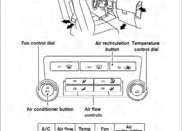
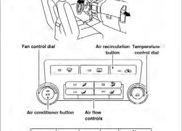
Temperature control dial The temperature control dial allows you to adjust the temperature of the outlet air. To lower the temperature, turn the dial to the left. To increase the temperature, turn the dial to the right.
WHA1384
Air recirculation button
Type A
Fan control dial Temperature control dial Air flow control dial Air conditioner button (if so equipped) Air recirculation button
1. 2. 3. 4. 5. CONTROLS Fan control dial The fan control dial turns the fan on and off, and controls fan speed.
Air flow control dial The air flow control dial allows you to select the air flow outlets. MAX A/C
— Air flows from center and side
vents with maximum cooling (air conditioning).
— Air flows from center and side
vents.
— Air flows from center and side
vents and the front and rear floor outlets.
ON position: to recir- Push the air recirculation button culate air inside the vehicle. The indicator light on the
button will come on.
button to the on position:
Push the ● when driving on a dusty road. ● to prevent traffic fumes from entering pas-
senger compartment.
● for maximum cooling when using the air con-
ditioner.
Heater, air conditioner, audio and phone systems 4-3
OFF position: Push the air recirculation button again to turn air recirculation off. The indicator light on button will turn off. Outside air is drawn the into the passenger compartment and distributed through the selected outlet. Use the off position for normal heater or air con- ditioner operation.
Air conditioner button (if so equipped)
The button is provided only on vehicles equipped with an air conditioner. Start the engine, turn the fan control dial to the desired (1 - 4) position and push the button to turn on the air conditioner. The indicator light comes on when the air conditioner is oper- ating. To turn off the air conditioner, push the The air conditioner cooling function oper- ates only when the engine is running.
button again.
HEATER OPERATION Heating This mode is used to direct heated air to the foot outlets. Some air also flows from the defrost outlets.
1. Push the
button to the OFF position for normal heating. The indicator light on the
button will go off.
2. Turn the air flow control dial to the
position.
3. Turn the fan control dial to the desired posi-
tion.
4. Turn the temperature control dial to the de- sired position between the middle and the hot position.
Ventilation This mode directs outside air to the side and center vent.
1. Push the
button to the OFF position. button will
The indicator light on the go off.
2. Turn the air flow control dial to the
position.
3. Turn the fan control dial to the desired posi-
tion.
4. Turn the temperature control dial to the de-
sired position.
Defrosting or defogging This mode directs the air to the defrost outlets to defrost/defog the windows.
1. Turn the air flow control dial to the
position.
2. Turn the fan control dial to the desired posi-
tion.
3. Turn the temperature control dial to the de- sired position between the middle and the hot position.
● To quickly remove ice or fog from the win- dows, turn the fan control dial to 4 and the temperature control lever to the full HOT position.
4-4 Heater, air conditioner, audio and phone systems
● When the
If
flow control dial
position is selected, the air conditioner automatically turns on (however, the indicator light will not illuminate) if the outside temperature is more than 36°F the air (2°C). is in position for more than one minute, the the air conditioning system will continue to operate until the fan control dial is turned to OFF or the vehicle is shut off, even if the air flow control dial is turned to a position other position. This dehumidifies than the the air which helps defog the windshield. mode automatically turns off, al- The lowing outside air to be drawn into the pas- senger compartment to further improve the defogging performance.
Bi-level heating This mode directs cooler air from the side and center vents and warmer air from the floor outlets. When the temperature control dial is moved to the full hot or full cool position, the air between the vents and the floor outlets is the same tem- perature.
1. Push the
button to the off position.
2. Turn the air flow control dial to the
position.
3. Turn the fan control dial to the desired posi-
tion.
4. Turn the temperature control dial to the de-
sired position.
Heating and defogging This mode heats the interior and defogs the wind- shield.
1. Turn the air flow control dial to the
position.
2. Turn the fan control dial to the desired posi-
tion.
3. Turn the temperature control dial to the de- sired position between the middle and the hot position.
● When the
position is selected, the air conditioner automatically turns on (however, button will the indicator light on the not come on) if the outside temperature is more than 36°F (2°C). If the air flow control position for more than dial is in the one minute, the air conditioning system will continue to operate until the fan control dial is turned to OFF or the vehicle is shut off, even if the air flow control dial is turned to a position. This position other than the dehumidifies the air which helps defog the mode automatically windshield. The turns off, allowing outside air to be drawn into the passenger compartment to further improve the defogging performance.
Operating tips Clear snow and ice from the wiper blades and air inlet in front of the windshield. This improves heater operation.
Heater, air conditioner, audio and phone systems 4-5
AIR CONDITIONER OPERATION (if so equipped) Start the engine, turn the fan control dial to the button to desired position, and push in the activate the air conditioner. When the air condi- tioner is on, cooling and dehumidifying functions are added to the heater operation. The air conditioner cooling function oper- ates only when the engine is running. Cooling This mode is used to cool and dehumidify the air.
● For quick cooling when the outside tem- button to perature is high, push the the on position (indicator light on). Be sure button to the off position to return the for normal cooling.
Dehumidified heating This mode is used to heat and dehumidify the air.
1. Push the
button to the off position.
2. Turn the air flow control dial to the
position.
3. Turn the fan control dial to the desired posi-
1. Push the
button to the off position.
tion.
2. Turn the air flow control dial to the
position.
4. Push the comes on.
button. The indicator light
3. Turn the fan control dial to the desired posi-
tion.
4. Push the comes on.
button. The indicator light
5. Turn the temperature control dial to the de-
sired position.
5. Turn the temperature control dial to the de-
sired position.
Dehumidified defogging This mode is used to defog the windows and dehumidify the air.
1. Turn the air flow control dial to the
position.
2. Turn the fan control dial to the desired posi-
tion.
4-6 Heater, air conditioner, audio and phone systems
3. Push the comes on.
button. The indicator light
is in the
When the air flow control dial or position, the air conditioner automati- cally turns on (however, the indicator light will not illuminate) if the outside temperature is more than 36°F (2°C). If one of these positions is selected for more than one minute, the air conditioning system will continue to operate until the fan con- trol dial is turned to OFF or the vehicle is shut off, even if the air flow control dial is turned to a position other than these positions. This dehu- midifies the air which helps defog the windshield. mode automatically turns off, allowing The outside air to be drawn into the passenger com- partment to further improve the defogging perfor- mance. 4. Turn the temperature control dial to the de-
sired position. Operating tips ● Keep the windows and moonroof (if so equipped) closed while the air conditioner is in operation.
● After parking in the sun, drive for two or three minutes with the windows open to vent hot air from the passenger compartment. Then, close the windows. This allows the air con- ditioner to cool the interior more quickly.
● The air conditioning system should be operated for approximately 10 minutes at least once a month. This helps pre- vent damage to the system due to lack of lubrication.
● A visible mist may be seen coming from the vents in hot, humid conditions as the air is cooled rapidly. This does not indicate a mal- function.
● If
the engine coolant
temperature gauge indicates engine coolant tem- perature over the normal range, turn the air conditioner off. See “If your vehicle overheats” in the “In case of emergency” section of this manual.
AIR FLOW CHARTS The following charts show the button and dial positions for MAXIMUM AND QUICK heating, cooling or defrosting. For additional information on heating and cooling, see “Heater and air con- ditioner (manual)” in this section. The air recir- ) button should always be in culation ( the OFF position for heating and defrost- ing.
Heater, air conditioner, audio and phone systems 4-7
WHA1385
4-8 Heater, air conditioner, audio and phone systems
WHA1386
WHA1387
WHA1388
WHA1389
Heater, air conditioner, audio and phone systems 4-9
HEATER AND AIR CONDITIONER (manual) (Type B)
WARNING
● The air conditioner cooling function op- erates only when the engine is running. ● Do not leave children or adults who would normally require the assistance of others alone in your vehicle. Pets should also not be left alone. They could accidentally injure themselves or others through inadvertent operation of the vehicle. Also, on hot, sunny days, temperatures in a closed vehicle could quickly become high enough to cause severe or possibly fatal injuries to people or animals.
● Do not use the recirculation mode for long periods as it may cause the interior air to become stale and the windows to fog up.
1. 2. 3.
Fan speed control dial Front window defroster button Rear window defroster switch (if so equipped) Air recirculation button Temperature control dial
4. 5. 6. Max A/C button 7. 8.
Air flow control buttons Air conditioner ON/OFF button
4-10 Heater, air conditioner, audio and phone systems
Type B
WHA1406
CONTROLS Fan control dial The fan control dial turns the fan on and off, and controls fan speed. Air flow control buttons The air flow control buttons allow you to select the air flow outlets. MAX A/C
— Air flows from center and side
vents with maximum cooling (air conditioning).
— Air flows from center and side
vents.
— Air flows from center and side
vents and foot outlets.
— Air flows mainly from foot outlets. — Air flows from defroster outlets and
foot outlets.
— Air flows mainly from defroster
outlets.
Temperature control dial The temperature control dial allows you to adjust the temperature of the outlet air. To lower the temperature, turn the dial to the left. To increase the temperature, turn the dial to the right.
Air recirculation button
ON position (Indicator light on): Interior air is recirculated inside the vehicle.
button to the on position when:
Press the ● driving on a dusty road. ● to prevent traffic fumes from entering pas-
senger compartment.
● for maximum cooling when using the air con-
ditioner.
OFF position (Indicator light off): Outside air is drawn into the passenger compart- ment and distributed through the selected outlet. Use the off position for normal heater or air con- ditioner operation.
Air conditioner button
Start the engine, turn the fan control dial to the desired position and push the button to turn on the air conditioner. The indicator light comes on when the air conditioner is operating. To turn off the air conditioner, push the button again. The air conditioner cooling function oper- ates only when the engine is running. Rear window and outside mirror defroster switch (if so equipped) For more information about the rear window de- froster switch, see “Rear window and outside mirror defroster switch” in the “Instruments and controls” section of this manual.
HEATER OPERATION Heating This mode is used to direct heated air to the foot outlets. Some air also flows from the defrost outlets.
1. Press the
button to the OFF position for normal heating. The indicator light on the
button will go off.
2. Press the
air flow control button.
3. Turn the fan control dial to the desired position.
4. Turn the temperature control dial to the de- sired position between the middle and the hot position.
Ventilation This mode directs outside air to the side and center vents.
1. Press the
The indicator light on the go off.
button to the OFF position. button will
2. Press the
air flow control button.
3. Turn the fan control dial to the desired position. 4. Turn the temperature control dial to the de-
sired position.
Heater, air conditioner, audio and phone systems 4-11
Defrosting or defogging This mode directs the air to the defrost outlets to defrost/defog the windows.
1. Press the defrost/defog button 2. Turn the fan control dial to the desired posi-
tion.
3. Turn the temperature control dial to the de- sired position between the middle and the hot position.
● To quickly remove ice or fog from the win-