- 2012 Nissan Frontier Owners Manuals
- Nissan Frontier Owners Manuals
- 2003 Nissan Frontier Owners Manuals
- Nissan Frontier Owners Manuals
- 2004 Nissan Frontier Owners Manuals
- Nissan Frontier Owners Manuals
- 2009 Nissan Frontier Owners Manuals
- Nissan Frontier Owners Manuals
- 2001 Nissan Frontier Owners Manuals
- Nissan Frontier Owners Manuals
- 2010 Nissan Frontier Owners Manuals
- Nissan Frontier Owners Manuals
- 1996 Nissan Frontier Owners Manuals
- Nissan Frontier Owners Manuals
- 2005 Nissan Frontier Owners Manuals
- Nissan Frontier Owners Manuals
- 2007 Nissan Frontier Owners Manuals
- Nissan Frontier Owners Manuals
- 2008 Nissan Frontier Owners Manuals
- Nissan Frontier Owners Manuals
- 1999 Nissan Frontier Owners Manuals
- Nissan Frontier Owners Manuals
- 2002 Nissan Frontier Owners Manuals
- Nissan Frontier Owners Manuals
- 2000 Nissan Frontier Owners Manuals
- Nissan Frontier Owners Manuals
- 2011 Nissan Frontier Owners Manuals
- Nissan Frontier Owners Manuals
- 1998 Nissan Frontier Owners Manuals
- Nissan Frontier Owners Manuals
- 1997 Nissan Frontier Owners Manuals
- Nissan Frontier Owners Manuals
- 2006 Nissan Frontier Owners Manuals
- Nissan Frontier Owners Manuals
- Download PDF Manual
-
again to toggle between (cid:176)F and (cid:176)C. Once you have selected (cid:176)F or (cid:176)C, the display will continue to flash for about 5 seconds, then the temperature will display.
COMPASS DISPLAY button for about 1 second when Push the the ignition key is in the ON position to toggle the outside temperature and compass direction dis- play s1 on or off. The display will indicate the direction of the vehicle(cid:146)s heading. N: North E: East S: South W: West If the display reads (cid:147)CAL(cid:148), calibrate the compass by driving the vehicle in three complete circles at less than 5 MPH (8 km/h). You can also calibrate the compass by driving your vehicle on your everyday route. The com- pass will be calibrated once it has tracked three complete circles.
2-10 Instruments and controls
Zone variation change procedure The difference between magnetic north and geo- graphical north is known as variance. In some areas, this difference can sometimes be great enough to cause false compass readings. Follow these instructions to set the variance for your particular location if this happens:
1. Press and hold the
button for about 8
seconds. The current zone number will ap- pear in the display. Release the button.2. Find your current location on the zone map.
Refer to the illustration.
3. Press the
button repeatedly to toggle through the zone numbers until the desired number appears in the display. Once you have selected a zone number, the display will show a compass direction within a few seconds.
NOTE:
Use zone number 5 for Hawaii.
Inaccurate compass direction
The compass display is equipped with automatic correction function. If the correct direction is not shown, follow this procedure.
Instruments and controls 2-11
WIC0355
CAUTION
c Do not install a ski rack, antenna, etc., which are attached to the vehicle by means of a magnet. They affect the op- eration of the compass.
c When cleaning the mirror, use a paper towel or similar material dampened with glass cleaner. Do not spray glass cleaner directly on the mirror as it may cause the liquid cleaner to enter the mirror housing.
1. With the display turned on, press and hold the button for about 10 seconds. The (cid:147)CAL(cid:148) icon in the compass display will illu- minate.
2. Calibrate the compass by driving the vehicle in three complete circles at a maximum speed of 5 MPH (8 km/h).
3. After completing the circles,
the display
should return to normal.
c If the compass deviates from the correct indication soon after repeated adjustment, have the compass checked at an authorized dealer.
c The compass may not indicate the correct compass point in tunnels or while driving up or down a steep hill. (The compass returns to the correct compass point when the ve- hicle moves to an area where the geomag- netism is stabilized.)
c If a magnet is located in or near the overhead console in the front of the vehicle or the vehicle is driven where the terrestrial mag- netism is disturbed, the compass display may not indicate the correct direction.
2-12 Instruments and controls
WARNING/INDICATOR LIGHTS AND AUDIBLE REMINDERS
or
Anti-lock Braking System (ABS) warning light
Automatic transmission oil temperature warning light (if so equipped)
Automatic transmission park warning light
model)
or
Brake warning light
Low windshield washer fluid warning light
Hill descent control system on indicator light (if so equipped)
Seat belt warning light and chime
Malfunction Indicator Light (MIL)
Supplemental air bag warning light
Overdrive off indicator light (A/T models only)
Automatic transmission position indicator light (if so equipped)
Security indicator light (if so equipped)
Charge warning light
Cruise main switch indicator light (if so equipped)
Slip indicator light for models with ABLS (if so equipped)
Door open warning light
Cruise set switch indicator light (if so equipped)
Slip indicator light for models with VDC (if so equipped)
Engine oil pressure warning light
Electronic locking rear differential (E-Lock) sys- tem on indicator light (if so equipped)
Transfer 4LO position indicator light
model)
4WD warning light (
model)
4WD shift indicator light (
model)
Turn signal/hazard indicator lights
Low fuel warning light
Front passenger air bag status light
Vehicle Dynamic Control (VDC) OFF indicator light (if so equipped)
Low tire pressure warning light
High beam indicator light (Blue)
Instruments and controls 2-13
If the ABS warning light illuminates while the engine is running, or while driving, it may indicate the ABS is not functioning properly. Have the system checked by a NISSAN dealer.
If an ABS malfunction occurs, the anti-lock func- tion is turned off. The brake system then operates normally, but without anti-lock assistance. See (cid:147)Brake system(cid:148) in the (cid:147)Starting and driving(cid:148) sec- tion.
Automatic transmission oil temperature warning light (if so equipped)
This light comes on when the automatic transmis- sion oil temperature is too high. If the light comes on while driving, reduce the vehicle speed as soon as safely possible until the light turns off.
CAUTION
Continued vehicle operation when the A/T oil temperature warning light is on may damage the automatic transmission.
Automatic transmission park model) warning light (
WARNING
c If the ATP light is ON, this indicates that the automatic transmission P (Park) po- sition will not function and the transfer case is in neutral.
c When parking, always make sure that the 4WD shift indicator light illuminates and the parking brake is set. Failure to engage the transfer position in 2WD, 4H or 4LO could result in the vehicle mov- ing unexpectedly, resulting in serious personal injury or property damage.
c Shift the 4WD switch into the 2WD, 4H or 4LO position again to turn off the ATP warning light when the shift selector is in the P position and the ATP warning light is ON. (Before shifting the 4WD switch into the 4LO position, move the shift selector into the N position once, shift the shift selector into P again and make sure the ATP warning light is OFF.)
CHECKING BULBS With all doors closed, apply the parking brake and turn the ignition key to the ON position without starting the engine. The following lights will come on:
or
The following lights come on briefly and then go off:
or
If any light fails to come on, it may indicate an open circuit in the electrical system. Have the system repaired promptly. WARNING LIGHTS
or
Anti-lock Braking System (ABS) warning light
When the ignition switch is placed in the ON position, the Anti-lock Braking System (ABS) warning light illuminates and then turns off. This indicates the ABS is operational.
2-14 Instruments and controls
This light indicates that the automatic transmis- sion parking function is not engaged. If the trans- fer control is not secured in any drive position while the shift selector is in the P (Park) position, the transmission will disengage and the drive wheels will not lock.
or
Brake warning light
This light functions for both the parking brake and the foot brake systems. Parking brake indicator When the ignition switch is placed in the ON position, the light comes on when the parking brake is applied. Low brake fluid warning light When the ignition switch is placed in the ON position, the light warns of a low brake fluid level. If the light comes on while the engine is running with the parking brake not applied, stop the ve- hicle and perform the following: 1. Check the brake fluid level. Add brake fluid as necessary. See (cid:147)Brake fluid(cid:148) in the (cid:147)Main- tenance and do-it-yourself(cid:148) section of this manual. If the brake fluid level is correct, have the warning system checked by a NISSAN dealer.
2.
WARNING
CAUTION
c Your brake system may not be working properly if the warning light is on. Driv- ing could be dangerous. If you judge it to be safe, drive carefully to the nearest service station for repairs. Otherwise, have your vehicle towed because driv- ing it could be dangerous.
c Pressing the brake pedal with the en- gine stopped and/or a low brake fluid level may increase your stopping dis- tance and braking will require greater pedal effort as well as pedal travel.
c If the brake fluid level
is below the MINIMUM or MIN mark on the brake fluid reservoir, do not drive until the brake system has been checked at a NISSAN dealer.
Charge warning light
If this light comes on while the engine is running, it may indicate the charging system is not func- tioning properly. Turn the engine off and check the generator belt. If the belt is loose, broken, missing, or if the light remains on, see a NISSAN dealer immediately.
c Do not ground electrical accessories directly to the battery terminal. Doing so will bypass the variable control sys- tem and the vehicle battery may not charge completely. Refer to (cid:147)Variable voltage control system(cid:148) in the (cid:147)Mainte- nance and do-it-yourself(cid:148) section later in this manual.
c Do not continue driving if the generator
belt is loose, broken or missing. Door open warning light
This light comes on when any of the doors are not closed securely while the ignition switch is placed in the ON position.
Engine oil pressure warning light
This light warns of low engine oil pressure. If the light flickers or comes on during normal driving, pull off the road in a safe area, stop the engine immediately and call a NISSAN dealer or other authorized repair shop.
Instruments and controls 2-15
The engine oil pressure warning light is not designed to indicate a low oil level. Use the dipstick to check the oil level. See (cid:147)Engine oil(cid:148) in the (cid:147)Maintenance and do-it-yourself(cid:148) section of this manual.
CAUTION
Running the engine with the engine oil pressure warning light on could cause se- rious damage to the engine almost imme- diately. Such damage is not covered by warranty. Turn off the engine as soon as it is safe to do so.
4WD warning light ( model)
The 4WD warning light comes on when the igni- tion switch is turned to ON. It turns off soon after the engine is started.
If the engine or vehicle is not functioning properly, the warning light will either remain illuminated or blink. See (cid:147)4WD warning light(cid:148) in the (cid:147)Starting and driving(cid:148) section.
2-16 Instruments and controls
CAUTION
Low fuel warning light
c If the warning light comes on or blinks during operation, have your vehicle checked by a NISSAN dealer as soon as possible.
c Do not drive on dry hard surface roads in the 4H or 4LO position. If the 4WD warning light turns on when you are driving on dry hard surface roads: (cid:150) in the 4H position, shift the 4WD shift
switch to 2WD.
(cid:150) in the 4LO position for automatic transmission models, stop the ve- hicle and shift the shift selector to the N position with the brake pedal depressed and shift the 4WD shift switch to 2WD.
(cid:150) in the 4LO position for manual trans- mission models, stop the vehicle and shift the shift selector to the N posi- tion with the clutch pedal depressed and shift the 4WD shift switch to 2WD,
c If the warning light is still on after the above operation, have your vehicle checked by a NISSAN dealer as soon as possible.
This light comes on when the fuel level in the fuel tank is getting low. Refuel as soon as it is conve- nient, preferably before the fuel gauge reaches E (Empty). There will be a small reserve of fuel in the tank when the fuel gauge needle reaches E (Empty).
Low tire pressure warning light
Your vehicle is equipped with a Tire Pressure Monitoring System (TPMS) that monitors the tire pressure of all tires except the spare.
The low tire pressure warning light warns of low tire pressure or indicates that the TPMS is not functioning properly.
After the ignition switch is placed in the ON position, this light illuminates for about 1 second and turns off. Low tire pressure warning: If the vehicle is being driven with low tire pressure, the warning light will illuminate. When the low tire pressure warning light illuminates, you should stop and adjust the tire pressure of all 4 tires to the recom- mended COLD tire pressure shown on the
Tire and Loading Information label located in the driver(cid:146)s door opening. The low tire pressure warning light does not automati- cally turn off when the tire pressure is ad- justed. After the tire is inflated to the rec- ommended pressure, the vehicle must be driven at speeds above 16 MPH (25 km/h) to activate the TPMS and turn off the low tire pressure warning light. Use a tire pres- sure gauge to check the tire pressure.
For additional information, see (cid:147)Tire Pressure Monitoring System (TPMS)(cid:148) in the (cid:147)Starting and driving(cid:148) section and in the (cid:147)In case of emergency(cid:148) section. TPMS malfunction:
If the TPMS is not functioning properly, the low tire pressure warning light will flash for approxi- mately 1 minute when the ignition switch is placed in the ON position. The light will remain on after the 1 minute. Have the system checked by a NISSAN dealer.
For additional information, see (cid:147)Tire Pressure Monitoring System (TPMS)(cid:148) in the (cid:147)Starting and driving(cid:148) section and (cid:147)Tire pressure(cid:148) in the (cid:147)Main- tenance and do-it-yourself(cid:148) section.
WARNING
c If the light does not illuminate with the ignition switch placed in the ON posi- tion, have the vehicle checked by a NISSAN dealer as soon as possible.
c If the light illuminates while driving, avoid sudden steering maneuvers or abrupt braking, reduce vehicle speed, pull off the road to a safe location and stop the vehicle as soon as possible. Driving with under-inflated tires may permanently damage the tires and in- crease the likelihood of tire failure. Se- rious vehicle damage could occur and may lead to an accident and could re- sult in serious personal injury. Check the tire pressure for all four tires. Adjust the tire pressure to the recommended COLD tire pressure shown on the Tire and Loading Information label located in the driver(cid:146)s door opening to turn the low tire pressure warning light OFF. If the light still comes on while driving after adjusting the tire pressure, a tire may be flat. If you have a flat tire, re- place it with a spare tire as soon as possible.
c When a spare tire is mounted or a wheel is replaced, the TPMS will not function and the low tire pressure warning light will flash for approximately 1 minute. The light will remain on after 1 minute. Contact your NISSAN dealer as soon as possible for tire replacement and/or system resetting.
c Replacing tires with those not originally specified by NISSAN could affect the proper operation of the TPMS.
CAUTION
c The TPMS is not a substitute for the regular tire pressure check. Be sure to check the tire pressure regularly.
c If the vehicle is being driven at speeds of less than 16 MPH (25 km/h), the TPMS may not operate correctly.
c Be sure to install the specified size of
tires to the 4 wheels correctly.
Instruments and controls 2-17
Low windshield washer fluid warning light
Supplemental air bag warning light
This light comes on when the windshield washer fluid is at a low level. Add windshield washer fluid as necessary. See (cid:147)Window washer fluid(cid:148) in the (cid:147)Maintenance and do-it-yourself(cid:148) section of this manual.
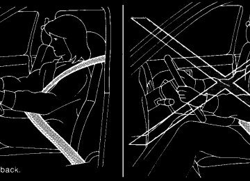
Seat belt warning light and chime
The light and chime remind you to fasten your seat belts. The light illuminates whenever the ignition switch is placed in the ON or START position and remains illuminated until the driver(cid:146)s seat belt is fastened. At the same time, the chime sounds for about 6 seconds unless the driver(cid:146)s seat belt is securely fastened.
The seat belt warning light may also illuminate if the front passenger(cid:146)s seat belt is not fastened when the front passenger(cid:146)s seat is occupied . For 7 seconds after the ignition switch is placed in the ON position, the system does not activate the warning light for the front passenger.
Refer to (cid:147)Seat belts(cid:148) in the (cid:147)Safety(cid:151)Seats, seat belts and supplemental restraint system(cid:148) section for precautions on seat belt usage.
2-18 Instruments and controls
When the ignition switch is in the ON or START position, the supplemental air bag warning light illuminates for about 7 seconds and then turns off. This means the system is operational.
If any of the following conditions occur, the front air bag, side air bag, curtain and roll-over air bag, and pretensioner systems need servicing and your vehicle must be taken to a NISSAN dealer: c The supplemental air bag warning light re-
mains on after approximately 7 seconds.
c The supplemental air bag warning light
flashes intermittently.
c The supplemental air bag warning light does
not come on at all.
Unless checked and repaired, the supplemental restraint system (air bag system) and/or the pre- tensioners may not function properly. For addi- tional details see (cid:147)Supplemental restraint sys- tem(cid:148) in the (cid:147)Safety(cid:151)Seats, seat belts and supplemental restraint system(cid:148) section of this manual.
WARNING
If the supplemental air bag warning light is on, it could mean that the front air bag, side air bag, curtain and roll-over air bag systems, and/or pretensioner systems will not operate in an accident. To help avoid injury to yourself or others, have your ve- hicle checked by a NISSAN dealer as soon as possible.
INDICATOR LIGHTS
Automatic transmission position indicator light (if so equipped)
See (cid:147)Driving the vehicle(cid:148) in the (cid:147)Starting and driving(cid:148) section of this manual.
Cruise main switch indicator light (if so equipped)
The light comes on when the cruise control main switch is pushed. The light goes out when the main switch is pushed again. When the cruise main switch indicator light comes on, the cruise control system is operational.
Cruise set switch indicator light (if so equipped)
4WD shift indicator light
model)
High beam indicator light (blue)
The light comes on while the vehicle speed is controlled by the cruise control system. If the light blinks while the engine is running, it may indicate the cruise control system is not functioning prop- erly. Have the system checked by a NISSAN dealer.
Electronic locking rear differential (E-Lock) system on indicator light (if so equipped)
This light comes on when the electronic locking rear differential (E-Lock) system clutch is fully engaged.
The indicator light flashes when the system is first turned on. When the system fully engages, the light remains on. If the switch is on and the indicator light continues to flash, the system is not engaged.
For additional information, see (cid:147)Electronic lock- ing rear differential (E-Lock) system switch(cid:148) later in this section and (cid:147)Electronic locking rear differ- ential (E-Lock) system(cid:148) in the (cid:147)Starting and driv- ing(cid:148) section of this manual.
The light should turn off within 1 second after placing the ignition switch in the ON position.
While the engine is running, the 4WD shift indi- cator light will illuminate the position selected by the 4WD shift switch. The 4WD shift indicator light may blink while shifting from one drive mode to the other.
Front passenger air bag status light
The front passenger air bag status light ( will be lit and the passenger front air bag will be OFF depending on how the front passenger seat is being used.
For front passenger air bag status light operation, see (cid:147)Front passenger air bag and status light(cid:148) in the (cid:147)Safety (cid:151) Seats, seat belts and supplemental restraint system(cid:148) section of this manual.
This blue light comes on when the headlight high beams are on and goes out when the low beams are selected.
The high beam indicator light also comes on when the passing signal is activated.
Hill descent control system on indicator light (if so equipped)
When the ignition switch is placed in the ON position, this light comes on briefly and then turns off.
The light comes on when the hill descent control system is activated.
If the hill descent control switch is on and the indicator light blinks, the system is not engaged.
If the indicator light does not come on or blink when the hill descent switch is on, the system may not be functioning properly. Have the system checked by a NISSAN dealer.
For additional information, see (cid:147)Hill descent con- trol switch(cid:148) later in this section and (cid:147)Hill descent control system(cid:148) in the (cid:147)Starting and driving(cid:148) sec- tion of this manual.
Instruments and controls 2-19
Malfunction Indicator Light (MIL)
If this indicator light comes on steady or blinks while the engine is running, it may indicate a potential emission control malfunction.
The Malfunction Indicator Light may also come on steady if the fuel-filler cap is loose or missing, or if the vehicle runs out of fuel. Check to make sure the fuel-filler cap is installed and closed tightly, and that the vehicle has at least 3 gallons (11.4 liters) of fuel in the fuel tank.
After a few driving trips, the light should turn off if no other potential emission control system malfunction exists.
If this indicator light comes on steady for 20
seconds and then blinks for 10 seconds when the engine is not running, it indicates that the vehicle is not ready for an emission control sys- tem inspection/maintenance test. See (cid:147)Readi- ness for inspection/maintenance (I/M) test(cid:148) in the (cid:147)Technical and consumer information(cid:148) section of this manual. OperationThe Malfunction Indicator Light will come on in one of two ways:
2-20 Instruments and controls
c Malfunction Indicator Light on steady (cid:151) An emission control system malfunction has been detected. Check the fuel-filler cap. If the fuel-filler cap is loose or missing, tighten or install the cap and continue to drive the light should turn off after vehicle. The a few driving trips. If the light does not turn off after a few driving trips, have the vehicle inspected by a NISSAN dealer. You do not need to have your vehicle towed to the dealer.
c Malfunction Indicator Light blinking (cid:151) An engine misfire has been detected which may damage the emission control system. To re- duce or avoid emission control system dam- age:
(cid:150) do not drive at speeds above 45 MPH
(72 km/h).
(cid:150) avoid hard acceleration or deceleration.
(cid:150) avoid steep uphill grades.
(cid:150) if possible, reduce the amount of cargo
being hauled or towed.
The Malfunction Indicator Light may stop blinking and come on steady. Have the vehicle inspected by a NISSAN dealer. You do not need to have your vehicle towed to the dealer.
CAUTION
Continued vehicle operation without hav- ing the emission control system checked and repaired as necessary could lead to poor driveability, reduced fuel economy, and possible damage to the emission con- trol system.
Overdrive OFF indicator light (A/T models only)
This light comes on when the overdrive function is OFF.
The automatic transmission overdrive function is controlled by the overdrive switch.
See (cid:147)Driving the vehicle(cid:148) in the (cid:147)Starting and driving(cid:148) section of this manual.
Security indicator light (if so equipped)
This light blinks when the ignition switch is in the OFF, LOCK or ACC position. The blinking secu- rity indicator light indicates that the security sys- tems equipped on the vehicle are operational.
For additional tems(cid:148) later in this section.
information, see (cid:147)Security sys-
Slip indicator light for models with ABLS (if so equipped)
If the light does not go off after performing the reset procedure, have the traction control system checked by a NISSAN dealer.
This indicator light comes on if the active brake limited slip is activated. If activated, the system will apply braking to the slipping drive wheel(s), giving the non-slipping wheel(s) more traction. Slip indicator light for models with VDC (if so equipped)
This indicator light will blink when the traction control system is limiting wheel spin. Slippery road conditions may exist if the slip indicator blinks on. If this happens, adjust your driving accordingly. The slip indicator light also comes on when you turn the ignition key to the ON position. The light will turn off after about 2 seconds if the system is operational. If the light does not come on or does not go off, have the traction control system checked by a NISSAN dealer. If the battery is removed or discharged, the trac- tion control system is disabled and the slip indi- cator light will not turn off after 2 seconds when the ignition switch is turned to the ON position. To reset the system, you must perform the reset procedure. Refer to (cid:147)Vehicle Dynamic Control (VDC) system(cid:148) in the (cid:147)Starting and driving(cid:148) sec- tion of this manual.
Transfer 4LO position indicator light (
model)
The light should turn off within 1 second after turning the ignition switch to ON. This light comes on when the 4WD shift switch is set in the 4LO position with the ignition switch in the ON position. The transfer case may be damaged if you shift the switch while driving. Make sure the transfer 4LO position indicator light turns on when you shift the 4WD shift switch to 4LO. The indicator light may blink while shifting from one drive mode to the other. The 4LO indicator light must stop blinking and remain illuminated or turn off before shifting the transmission into gear. If the shift selector is shifted from the N (Neutral) position to any other gear when the 4LO indicator light is blinking, the vehicle may move unexpectedly.
When you shift between 4H and 4LO, follow the instructions below: c For automatic transmission models, stop the vehicle and shift the shift selector to the N (Neutral) position with the brake pedal de- pressed, then depress and turn the 4WD shift switch to 4LO or 4H.
c For manual transmission models, stop the vehicle and shift the shift selector to the N (Neutral) position with the clutch pedal de- pressed, then depress and turn the 4WD shift switch to 4LO or 4H.
You cannot move the transfer 4WD shift switch between 4H and 4LO unless you stop the vehicle and shift the shift selector to the N position with the brake pedal (AT models) or clutch pedal (MT models) depressed.
Turn signal/hazard indicator lights
The appropriate light flashes when the turn signal switch is activated.
Both lights flash when the hazard switch is turned on.
Instruments and controls 2-21
Key reminder chime A chime sounds if the driver(cid:146)s door is opened while the key is left in the ignition switch. Remove the key and take it with you when leaving the vehicle. Light reminder chime With the ignition switch placed in the OFF posi- tion, a chime sounds when the driver(cid:146)s door is opened if the headlights or parking lights are on. Turn the headlight control switch off before leav- ing the vehicle.
Vehicle Dynamic Control (VDC) OFF indicator light (if so equipped)
This indicator light comes on when the Vehicle Dynamic Control off switch is pushed to OFF, the transfer case is in the 4LO position ( model), or when the Vehicle Dynamic Control system is not functioning properly. This indicates the Vehicle Dynamic Control system is not oper- ating.
Push the Vehicle Dynamic Control off switch again or restart the engine and the system will operate normally. See (cid:147)Vehicle Dynamic Control (VDC) system(cid:148) in the (cid:147)Starting and driving(cid:148) sec- tion of this manual.
The Vehicle Dynamic Control light also comes on when you turn the ignition key to the ON position. The light will turn off after about 2 seconds if the system is operational. If the light stays on or comes on along with the SLIP indicator light while you are driving, have the Vehicle Dynamic Control system checked by a NISSAN dealer. If the battery is removed or discharged, the Ve- hicle Dynamic Control system is disabled and the VDC indicator light will not turn off after 2 sec- onds when the ignition switch is turned to the ON position. To reset the system, you must perform 2-22 Instruments and controls
the reset procedure. Refer to (cid:147)Vehicle Dynamic Control (VDC) system(cid:148) in the (cid:147)Starting and driv- ing(cid:148) section of this manual.
If the light does not go off after performing the reset procedure, have the traction control system checked by a NISSAN dealer.
While the Vehicle Dynamic Control system is operating, you might feel slight vibration or hear the system working when starting the vehicle or accelerating, but this is normal.
The VDC system will be disabled and the VDC light will illuminate when the electronic locking rear differential (E-lock) system switch (if so equipped) is turned on and the E-lock system is engaged. If the E-lock system disengages or the switch is turned off, the VDC system will be enabled and the VDC light will turn off. AUDIBLE REMINDERS Brake pad wear warning The disc brake pads have audible wear warnings. When a disc brake pad requires replacement, it makes a high pitched scraping sound when the vehicle is in motion, whether or not the brake pedal is depressed. Have the brakes checked as soon as possible if the warning sound is heard.
SECURITY SYSTEMS (if so equipped)
LIC0359
Your vehicle may have two types of security sys- tems: c Vehicle security system (if so equipped) c NISSAN Vehicle Immobilizer System (if soequipped)
VEHICLE SECURITY SYSTEM (if so equipped) The vehicle security system provides visual and audible alarm signals if someone opens the doors when the system is armed. It is not, however, a motion detection-type system that activates when a vehicle is moved or when a vibration occurs.
The system helps deter vehicle theft but cannot prevent it, nor can it prevent the theft of interior or exterior vehicle components in all situations. Al- ways secure your vehicle even if parking for a brief period. Never leave your keys in the ignition, and always lock the vehicle when unattended. Be aware of your surroundings, and park in secure, well-lit areas whenever possible. Many devices offering additional protection, such as component locks, identification markers, and tracking systems, are available at auto supply stores and specialty shops. Your NISSAN dealer may also offer such equipment. Check with your insurance company to see if you may be eligible for discounts for various theft protection features. How to arm the vehicle security system 1. Close all windows. (The system can be armed even if the windows are open.)
2. Remove the key from the ignition switch. 3. Close all doors. Lock all doors. The doors can be locked with the key, power door lock switch (if the door is opened, locked and then closed), or with the keyfob.
Keyfob operation:
c Push the
button on the keyfob. All doors lock. The hazard lights flash twice and the horn beeps once to indicate all doors are locked.
c When the
button is pushed with all doors locked, the hazard lights flash twice and the horn beeps once as a re- minder that the doors are already locked.
The horn may or may not beep. Refer to (cid:147)Silencing the horn beep feature(cid:148) in the (cid:147)Pre-driving checks and adjustments(cid:148) sec- tion later in this manual.
4. Confirm that the
indicator light comes on. The light stays on for about 30
seconds. The vehicle security system is now pre-armed. After about 30 seconds the ve- hicle security system automatically shifts into the armed phase. The light begins to flash once every 3 seconds. If, during the 30-second pre-arm time period, the driver(cid:146)s door is unlocked by the key or the keyfob, or the ignition switch is placed in ACC or ON position, the system will not arm.Instruments and controls 2-23
c If the key is turned slowly when locking the driver(cid:146)s door, the system may not arm. Furthermore, if the key is turned beyond the vertical position toward the unlock position to remove the key, the system may be disarmed when the key is removed. If the indicator light fails to glow for 30 seconds, unlock the door once and lock it again.
c Even when the driver and/or passen- gers are in the vehicle, the system will arm with all doors closed and locked with the ignition switch placed in the OFF position.
Vehicle security system activation The vehicle security system will give the following alarm: c The headlights blink and the horn sounds
intermittently.
c The alarm automatically turns off after ap- proximately 50 seconds. However, the alarm reactivates if the vehicle is tampered with again. The alarm can be shut off by unlocking the driver(cid:146)s door with the key or by pressing the
button on the keyfob.
2-24 Instruments and controls
The alarm is activated by: c opening a door without using the key or keyfob (even if the door is unlocked by using the inside lock knob or the power door lock switch).
How to stop an activated alarm The alarm stops only by unlocking the driver(cid:146)s door with the key or by pressing the button on the keyfob. NISSAN VEHICLE IMMOBILIZER SYSTEM (if so equipped) The NISSAN Vehicle Immobilizer System will not allow the engine to start without the use of a registered key.
If the engine fails to start using a registered key (for example, when interference is caused by another registered key, an automated toll road device or automatic payment device on the key ring), restart the engine using the following pro- cedures:
1. Leave the ignition switch in the ON position
for approximately 5 seconds.
2. Turn the ignition switch to the OFF or LOCK position, and wait approximately 10 sec- onds.
3. Repeat steps 1 and 2. 4. Restart the engine while holding the device (which may have caused the interference) separate from the registered key.
If the no start condition re-occurs, NISSAN rec- ommends placing the registered key on a sepa- rate key ring to avoid interference from other devices. Statement related to Section 15 of FCC Rules for NISSAN Vehicle Immobilizer Sys- tem (CONT ASSY (cid:151) IMMOBILIZER, ANT ASSY (cid:151) IMMOBILIZER) This device complies with part 15 of the FCC Rules and RSS-210 of Industry Canada. Operation is subject to the follow- ing two conditions; (1) This device may not cause harmful in- terference, and (2) this device must accept any interference received, including inter- ference that may cause undesired opera- tion of the device. CHANGES OR MODIFICATIONS NOT EX- PRESSLY APPROVED BY THE PARTY RE- SPONSIBLE FOR COMPLIANCE COULD VOID THE USER(cid:146)S AUTHORITY TO OPER- ATE THE EQUIPMENT.
WINDSHIELD WIPER AND WASHER SWITCH
LIC0474
WIC0854
Security indicator light The security indicator light blinks whenever the ignition switch is placed in the LOCK, OFF or ACC position. This function indicates the NISSAN Ve- hicle Immobilizer System is operational. If the NISSAN Vehicle Immobilizer System is mal- functioning, the light will remain on while the ignition switch is placed in the ON position. If the light still remains on and/or the en- gine will not start, see a NISSAN dealer for NISSAN Vehicle Immobilizer System ser- vice as soon as possible. Please bring all registered keys that you have when visiting your NISSAN dealer for service.
SWITCH OPERATION The windshield wiper and washer operates when the ignition switch is placed in the ON position.
Push the lever down to operate the wiper at the following speed: s1
Intermittent (INT) (cid:151) intermittent operation can be adjusted by turning the knob toward sA (Slower) or sB (Faster). s2
Low (LO) (cid:151) continuous low speed operation s3 High (HI) (cid:151) continuous high speed opera-tion
Push the lever up s4 to have one sweep opera- tion (MIST) of the wiper. Pull the lever toward you s5
to operate the washer. The wiper will also operate several times.WARNING
In freezing temperatures the washer solu- tion may freeze on the windshield and obscure your vision which may lead to an accident. Warm the windshield with the defroster before you wash the windshield.
CAUTION
c Do not operate the washer continu-
ously for more than 30 seconds.
c Do not operate the washer if the reser-
voir tank is empty.
c Do not fill the window washer reservoir tank with washer fluid concentrates at full strength. Some methyl alcohol based washer fluid concentrates may permanently stain the grille if spilled while filling the window washer reser- voir tank.
Instruments and controls 2-25
REAR WINDOW AND OUTSIDE MIRROR DEFROSTER SWITCH (if so equipped)
HEADLIGHT AND TURN SIGNAL SWITCH
c Pre-mix washer fluid concentrates with water to the manufacturer(cid:146)s recom- mended levels before pouring the fluid into the window washer reservoir tank. Do not use the window washer reservoir tank to mix the washer fluid concen- trate and water.
LIC1419
To defrost the rear window glass and outside mirrors (if so equipped), start the engine and push the rear window defroster switch on. The rear window defroster light on the switch comes on. Push the switch again to turn the defroster off. The rear window defroster automatically turns off after approximately 15 minutes.
indicator
CAUTION
When cleaning the inner side of the rear window, be careful not to scratch or dam- age the rear window defroster.
2-26 Instruments and controls
Type A
WIC1424
HEADLIGHT CONTROL SWITCH Lighting s1 When turning the switch to the
posi- tion, the front parking, tail, license plate and instrument panel lights come on. s2 When turning the switch to the
posi- tion, the headlights come on and all the other lights remain on.
WIC1452
WIC1426
WIC1453
Type B
CAUTION
Use the headlights with the engine run- ning to avoid discharging the vehicle battery.
Type C
Autolight system (if so equipped) The autolight system allows the headlights to be set so they turn on and off automatically. The autolight system can: c Turn on the headlights, front parking, tail, license plate and instrument panel lights au- tomatically when it is dark.
c Turn off all the lights when it is light. c Keep all the lights on for 45 seconds after you turn the key to OFF and all doors are closed.
Instruments and controls 2-27
To turn on the autolight system: 1. Turn the headlight switch to the AUTO posi-
tion s1 .
2. Turn the ignition switch to ON. 3. The autolight system automatically turns the
headlights on and off.
Initially, if the ignition switch is turned OFF and a door is opened and left open, the headlights remain ON for 5 minutes. If another door is opened during the 5 minutes, then the 5 minute timer is reset. To turn the autolight system off, turn the switch to the OFF,
position.
, or
2-28 Instruments and controls
LIC0835
Be sure you do not put anything on top of the autolight sensor s1 located in the top side of the instrument panel. The autolight sensor controls the autolight; if it is cov- ered, the autolight sensor reacts as if it is dark out and the headlights will illuminate. If this occurs while parked with the engine off and the switch in the ON position, your vehicle(cid:146)s battery could become discharged.WIC1427
Headlight beam select s1 To select the high beam function, push the lever forward. The high beam lights come on and the
light illuminates.
s2 Pull the lever back to select the low beam. s3 Pulling and releasing the lever flashes the
headlight high beams on and off.
Battery saver system If the ignition switch is placed in the OFF position while the headlight switch is in the or 5 minutes.
position, the headlights will turn off after
After the headlights automatically turn off with the position, headlight switch in the the headlights will illuminate again for 5 minutes if the headlight switch is moved to the OFF position and then turned to the position.
or
or
CAUTION
Even though the battery saver feature au- tomatically turns off the headlights after a period of time, you should turn the head- light switch to the OFF position when the engine is not running to avoid discharging the vehicle battery. DAYTIME RUNNING LIGHT SYSTEM (Canada only) The headlights automatically illuminate at a re- duced intensity when the engine is started with the parking brake released. The daytime running lights operate with the headlight switch in the OFF position or in the position. Turn the headlight switch to the position for full illumination when driving at night.
If the parking brake is applied before the engine is started, the daytime running lights do not illumi- nate. The daytime running lights illuminate when the parking brake is released. The daytime run- ning lights will remain on until the ignition switch is placed in the OFF position.
WARNING
When the daytime running light system is active, tail lights on your vehicle are not on. It is necessary at dusk to turn on your headlights. Failure to do so could cause an accident injuring yourself and others.
WIC0917
INSTRUMENT BRIGHTNESS CONTROL The instrument brightness control operates when the headlight control switch is in the AUTO (if so equipped), Turn the control sA to adjust the brightness of the instrument panel lights when driving at night.
position.
or
Instruments and controls 2-29
HAZARD WARNING FLASHER SWITCH
LIC0394
Push the switch on to warn other drivers when you must stop or park under emergency condi- tions. All turn signal lights flash.WARNING
c If stopping for an emergency, be sure to
move the vehicle well off the road.
c Do not use the hazard warning flashers while moving on the highway unless unusual circumstances force you to drive so slowly that your vehicle might become a hazard to other traffic.
c Turn signals do not work when the haz-
ard warning flasher lights are on.
WIC1428
TURN SIGNAL SWITCH Turn signal s1 Move the lever up or down to signal the turning direction. When the turn is com- pleted, the turn signals cancel automatically.
Lane change signal s2 To signal a lane change, move the lever up or down to the point where the indicator light begins to flash, but the lever does not latch.
2-30 Instruments and controls
position.
LIC0393
FOG LIGHT SWITCH (if so equipped) To turn the fog lights on, turn the headlight switch to the position, then turn the fog light switch to the To turn the fog lights on with the headlight switch in the AUTO position (if so equipped), the head- lights must be on, then turn the fog light switch to the To turn the fog lights off, turn the fog light switch to the OFF position. The headlights must be on and the low beams selected for the fog lights to operate. The fog lights automatically turn off when the high beam headlights are selected.position.
HORN
CARGO LAMP SWITCH
The flashers will operate with the ignition switch placed in any position. Some state laws may prohibit the use of the hazard warning flasher switch while driving.
WIC1449
To sound the horn, push the area between the horn icons on the steering wheel.
WARNING
Do not disassemble the horn. Doing so could affect proper operation of the supplemental front air bag system. Tam- pering with the supplemental front air bag system may result in serious personal injury.
LIC0616
To turn on the cargo lamp, push the switch down to the ON position.CAUTION
Be sure to turn the light switch to the OFF position when you leave the vehicle for extended periods of time, otherwise the battery will go dead.
Instruments and controls 2-31
HEATED SEAT (if so equipped)
VEHICLE DYNAMIC CONTROL (VDC) OFF SWITCH (if so equipped)
CAUTION
c Do not use the seat heater for extended periods or when no one is using the seat.
c Do not put anything on the seat which insulates heat, such as a blanket, cush- ion, seat cover, etc. Otherwise, the seat may become overheated.
c Do not place anything hard or heavy on the seat or pierce it with a pin or similar object. This may result in damage to the heater.
c Any liquid spilled on the heated seat should be removed immediately with a dry cloth.
c When cleaning the seat, never use gasoline, benzine, thinner, or any simi- lar materials.
c If any abnormalities are found or the heated seat does not operate, turn the switch off and have the system checked by your NISSAN dealer.
c The battery could run down if the seat heater is operated while the engine is not running.
WIC0534
The vehicle should be driven with the Vehicle Dynamic Control (VDC) system on for most driv- ing conditions.If the vehicle is stuck in mud or snow, the VDC system reduces the engine output to reduce wheel spin. The engine speed will be reduced even if the accelerator is depressed to the floor. If maximum engine power is needed to free a stuck vehicle, turn the VDC system off. To turn off the VDC system, push the VDC OFF switch. The Push the VDC OFF switch again or restart the engine to turn on the system. See (cid:147)Vehicle Dynamic Control (VDC) system(cid:148) in the (cid:147)Starting and driving(cid:148) section.
indicator will come on.
LIC1041
The front seats are warmed by built-in heaters.
1. Start the engine.
2. Push the LO or HI position of the switch, as desired, depending on the temperature. The indicator light in the switch will illuminate.
The heater is controlled by a thermostat, automatically turning the heater on and off. The indicator light will remain on as long as the switch is on.
3. When the seat is warmed or before you leave the vehicle, be sure to turn the switch off.
2-32 Instruments and controls
HILL DESCENT CONTROL SWITCH (if so equipped)
LIC0743
WARNING
c Never rely solely on the hill descent control system to control vehicle speed when driving on steep downhill grades. Always drive carefully when using the hill descent control system and decel- erate the vehicle speed by depressing the brake pedal if necessary. Be espe- cially careful when driving on frozen, muddy or extremely steep downhill roads. Failure to control vehicle speed may result in a loss of control of the vehicle and possible serious injury or death.
c The hill descent control may not control the vehicle speed on a hill under all load or road conditions. Always be prepared to depress the brake pedal to control vehicle speed. Failure to do so may re- sult in a collision or serious personal injury.
CAUTION
When the hill descent control system op- erates continuously for a long time, the temperature of the brake pads may in- crease and the hill descent control system may be temporarily disabled (the indicator light will blink). If the indicator light does not come on continuously after blinking, stop using the system.
The hill descent control system is designed to reduce driver workload when going down steep hills. The hill descent control system helps to control vehicle speed so the driver can concen- trate on steering the vehicle.
To activate the hill descent control system: c the 4WD switch must be in the 4L position and the vehicle speed must be under 15
mph (25 km/h) orc the 4WD switch must be in the 4H position and the vehicle speed must be under 21
mph (35 km/h), andc the hill descent control system switch must
be ON.
The hill descent control system on indicator light will come on when the system is activated. Also, the stop/tail lights illuminate while the hill descent control system applies the brakes to control ve- hicle speed. If the accelerator or brake pedal is depressed while the hill descent control system is on, the system will stop operating temporarily. As soon as the accelerator or brake pedal is released, the hill descent control system begins to function again if the hill descent control operating condi- tions are fulfilled. The hill descent control system on indicator light blinks if the switch is on and all conditions for system activation are not met or if the system becomes disengaged for any reason. To turn off the hill descent control system, push the switch to the OFF position. For additional information, see (cid:147)Hill descent con- trol system on indicator light(cid:148) earlier in this sec- tion and (cid:147)Hill descent control system(cid:148) in the (cid:147)Starting and driving(cid:148) section of this manual.
Instruments and controls 2-33
ELECTRONIC LOCKING REAR DIFFERENTIAL (E-Lock) SYSTEM SWITCH (if so equipped)
LIC0729
The Electronic Locking Rear Differential (E-Lock) system can help provide added traction if the vehicle is stuck or becoming stuck. To activate the E-Lock system: c the 4WD switch must be in the 4LO position(4-wheel drive vehicles),
c the vehicle must be stopped or moving at 4
mph (7 km/h) or less, and
c the E-Lock system switch must be turned
ON.
2-34 Instruments and controls
When the E-Lock switch is turned ON, the indi- cator light will flash until the system engages. However, if all operation conditions listed above are not met or the system becomes disengaged, the indicator light will continue to flash.
The Anti-Lock Brake (ABS) system is disabled and the ABS light illuminates when the E-Lock system is ON. Also, the Vehicle Dynamic Control (VDC) system is disabled and the VDC light illuminates when the E-Lock system is ON.
See (cid:147)Electronic locking rear differential (E-Lock) system(cid:148) in the (cid:147)Starting and Driving(cid:148) section for further explanation and system limitations.
WARNING
c Never leave the E-Lock system ON when driving on paved or hard-surfaced roads. Turning the vehicle may result in the rear wheels slipping and result in an accident and personal injury. After us- ing the E-Lock system to free the ve- hicle, turn the system OFF.
c Use the E-Lock system only when free- ing a stuck vehicle. Try the 4LO position before using the E-Lock system. Never use the E-Lock system on a slippery road surface such as snow or ice sur- face. Using the E-Lock system when driving in these road conditions may cause unexpected movement of the ve- hicle during engine braking, accelerat- ing or turning, which may result in an accident and serious personal injury.
CAUTION
c After using the E-Lock system, turn the switch OFF to prevent possible damage to driveline components from extended use.
c Do not drive over 12 MPH (20 km/h) when the system is engaged. Doing so could result in possible damage to the driveline.
c Do not turn on the E-lock system while the tires are spinning. Doing so could damage drivetrain components.
CLUTCH INTERLOCK (clutch start) SWITCH (if so equipped)
POWER OUTLET
To use the clutch interlock switch: 1. Set the parking brake. 2. Depress the brake pedal with your right foot. 3. Place your left foot on the brake pedal and
release the parking brake.
4. Turn the ignition switch to the ON position. 5. Press and release the clutch interlock switch. The CANCEL light on the switch will illuminate.
6. Turn the ignition to the START position to start the engine and, at the same time, de- press the accelerator pedal with your right foot. As the vehicle begins to move, take your left foot off the brake. Once the engine has started, the clutch interlock switch CANCEL light shuts off. Do not use the interlock switch to start the engine under normal driving conditions.
WIC0817
WARNING
Pay special attention to your surround- ings when using the clutch interlock switch. The vehicle will move forward or backward according to the gear selected.
The clutch interlock (clutch start) switch allows for starting the engine without depressing the clutch pedal. This feature helps you restart the engine if it stops under difficult conditions. (For example, the engine stops on a steep hill and a slight movement forward or backward might be dangerous.)
Front row
LIC1430
The power outlets are for powering electrical accessories such as cellular telephones. The bottom power outlet located on instrument panel is powered directly by the vehicle(cid:146)s battery. The power outlet located inside the center con- sole is powered only when the ignition switch is in the ACC or ON position. Open the cap to use a power outlet.
Instruments and controls 2-35
c Use power outlets with the engine run- ning to avoid discharging the vehicle battery.
c Avoid using power outlets when the air conditioner, headlights or rear window defroster is on.
c Before inserting or disconnecting a plug, be sure the electrical accessory being used is turned OFF.
c Push the plug in as far as it will go. If good contact is not made, the plug may overheat or the internal temperature fuse may open.
c When not in use, be sure to close the cap. Do not allow water to contact the outlet.
STORAGE
LIC1539
Top center tray
STORAGE TRAYS
WARNING
Do not place sharp objects in the trays to help prevent injury in an accident or sud- den stop.
LIC0761
Center console
CAUTION
c The outlet and plug may be hot during
or immediately after use.
c Only certain power outlets are designed for use with a cigarette lighter unit. Do not use any other power outlet for an accessory lighter. See your NISSAN dealer for additional information.
c Do not use with accessories that ex- ceed a 12 volt, 120W (10A) power draw. Do not use double adapters or more than one electrical accessory.
2-36 Instruments and controls
AT model
MT model (cid:151) Type A (if so equipped)
MT model (cid:151) Type B (if so equipped)
LIC0818
WIC1431
WIC1432
Instruments and controls 2-37
UNDER-SEAT STORAGE BINS
WARNING
c Properly secure all cargo with ropes or straps to help prevent it from sliding or shifting. In a sudden stop or collision, unsecured cargo could cause personal injury.
c The cargo restrained in the under-seat storage bins must not exceed the weight limits listed below or the bins may not stay secured. In a sudden stop or collision, the unsecured bins could cause personal inury. King cab model: 16 lb (7.25 kg) Crew cab model
Driver(cid:146)s side: 16 lb (7.25 kg) Passenger(cid:146)s side: 25 lb (11.33 kg)
c If the under-seat storage bins are re- moved for any reason, they should be securely stored to prevent them from causing injury to passengers or damage to the vehicle in case of sudden braking or an accident.
2nd row under-seat storage bin
(King cab model)
2nd row under-seat storage bin
(Crew cab model)
LIC0821
LIC0820
2-38 Instruments and controls
c Do not place sharp objects in the under- seat storage bins. Such objects may become dangerous projectiles and cause injury when the vehicle is moving or if the vehicle is involved in a collision.
To access the under-seat storage bins: For King cab model, lift up the jump seat. Refer to (cid:147)Jump seat(cid:148) in the (cid:147)Safety(cid:151)Seats, seat belts and supplemental restraint system(cid:148) section earlier in this manual. For Crew cab model, lift up the rear bench seat. Refer to (cid:147)Folding the rear bench seat(cid:148) in the (cid:147)Safety(cid:151)Seats, seat belts and supplemental re- straint system(cid:148) section earlier in this manual.
LIC0822
LIC0766
CONSOLE BOX Pull up on the lever s1 to open the console box lid s2 .
To remove the under-seat storage bins: 1. Remove the storage net. 2. Remove the tray by lifting it out of the stor-
age bin (King cab model).
3. Turn the knobs to the UNLOCK position s2 . To install the under-seat storage bins: 1. Position the under-seat storage bin so the holes line up with the holes in the floorboard. Insert the knobs and turn them to the LOCK position s1 .
2.
Instruments and controls 2-39
CAUTION
c Do not use for anything other than
sunglasses.
c Do not leave sunglasses in the sun- glasses holder while parking in direct sunlight. The heat may damage the sunglasses.
LIC0768
WIC0673
GLOVE BOX To open the top portion of the glove box, push the latch sA up and raise the lid. To open the lower portion of the glove box, pull the handle sB down and lower the lid.
WARNING
Keep glove box lid closed while driving to help prevent injury in an accident or a sudden stop.
SUNGLASSES HOLDER (if so equipped) To open the sunglasses holder, push and release.
WARNING
c Keep the sunglasses holder closed
while driving to prevent an accident.
2-40 Instruments and controls
MAP POCKETS
WIC0824
LIC0826
LIC0825
King cab model
Crew cab model
Instruments and controls 2-41
CAUTION
c Avoid abrupt starting and braking when the cup holder is being used to prevent spilling the drink. If the liquid is hot, it can scald you or your passenger.
c Use only soft cups in the cup holder. Hard objects can injure you in an accident.
LIC0575
SEAT POCKET (if so equipped) A pocket is located on the back of the driver(cid:146)s seat.
WIC0827
Front
CUP HOLDERS The front cup holders have adapters that can be removed to accommodate larger cups.
WARNING
The cup holder should not be used while driving so full attention may be given to vehicle operation.
2-42 Instruments and controls
2nd row (rear of front console)
Bottle holder (front row)
Bottle holder (2nd row, Crew cab)
WIC0771
LIC0784
WIC0828
To open the 2nd row cup holders (rear of the front console), lower the lid. To close, raise the lid. If stepped on, the cup holder is designed to snap loose from the console. To re-install, close the cup holder assembly and push it back into the console opening. To fold the 2nd row bench seat back, first close the cup holder.
CAUTION
c Do not use bottle holder for any other objects that could be thrown about in the vehicle and possibly injure people during sudden braking or an accident. c Do not use bottle holder for open liquid
containers.
Instruments and controls 2-43
ROOF RACK (if so equipped)
WARNING
c Drive extra carefully when the vehicle is loaded at or near the cargo carrying capacity, especially if the significant portion of that load is carried on the roof rack.
c Heavy loading of the roof rack has the potential to affect the vehicle stability and handling during sudden or abnor- mal handling maneuvers.
c Roof
rack load should be evenly
distributed.
WIC0857
c Do not exceed maximum roof rack load
weight capacity.
c Properly secure all cargo with ropes or straps to help prevent it from sliding or shifting. In a sudden stop or collision, unsecured cargo could cause personal injury.
CAUTION
Use care when placing or removing items from the roof rack. If you cannot comfort- ably lift the items onto the roof rack from the ground, use a ladder or stool.
2-44 Instruments and controls
To remove: 1. Loosen the adjusting screws with the Torxdriver s1 by turning counterclockwise sA .
2. Rotate the clamps sC . 3. Remove the crossbar. 4. Reverse to install. 5. Always check the tightness of the crossbar
adjusting screws.
If you hear wind noise coming from the roof rack while driving, adjust the roof rack crossbar to the neutral position, rearward of D on the side rails.
Always evenly distribute the cargo on the tubular roof rack. The maximum total load is 125 lb (56 kg) evenly distributed. Be careful that your vehicle does not exceed the Gross Vehicle Weight Rating (GVWR) or the Gross Axle Weight Ratings (GAWR front and rear). The GVWR and GAWR are located on the F.M.V.S.S. label (located on the driver(cid:146)s side door jamb pillar). For more information regarding GVWR and GAWR, refer to (cid:147)Vehicle loading information(cid:148) in the (cid:147)Technical and consumer information(cid:148) sec- tion later in this manual.
The front crossbar can be adjusted or removed. Use the Torxdriver provided in the tool kit to loosen both crossbar adjusting screws. To adjust: 1. Loosen the adjusting screws with the Torxdriver s1 by turning counterclockwise sA .
2. When the clamp is loosened, move the crossbar so the cargo can be positioned on the crossbar sB .
3. Tighten the crossbar adjusting screws with
the Torxdriver by turning clockwise.
4. Secure the cargo with rope. 5. Always check the tightness of the crossbar
adjusting screws.
WINDOWS
POWER WINDOWS (if so equipped)
WARNING
c Make sure that all passengers have their hands, etc. inside the vehicle while it is in motion and before closing the windows. Use the window lock switch to prevent unexpected use of the power windows.
c Do not leave children unattended inside the vehicle. They could unknowingly ac- tivate switches or controls and become trapped in a window. Unattended chil- dren could become involved in serious accidents.
The power windows operate when the ignition switch is placed in the ON position, or for about 45 seconds after the ignition switch is placed in the OFF position. If the driver(cid:146)s or passenger(cid:146)s door is opened during this period of about 45
seconds, power to the windows is canceled.Instruments and controls 2-45
Driver(cid:146)s side power window switch The driver(cid:146)s side control panel is equipped with switches to open or close the front and rear passenger windows. To open a window, push the switch and hold it down. To close a window, pull the switch and hold it up. To stop the opening or closing function at any time, simply release the switch.
LIC1329
1. Window lock button 2. 3. 4.
Power door lock switch Front passenger side window switch Right rear passenger window switch (Crew Cab models only) Left rear passenger window switch (Crew Cab models only) Driver(cid:146)s side automatic switch
5.
6.
2-46 Instruments and controls
LIC0786
Front passenger(cid:146)s power window switch The passenger(cid:146)s window switch operates only the corresponding passenger(cid:146)s window. To open the window, push the switch and hold it down s1 . To close the window, pull the switch up s2 .
LIC0787
LIC0410
Rear power window switch (Crew Cab models only) The rear power window switches open or close only the corresponding passenger window. To open the window, push the switch and hold it down s1 . To close the window, push the switch up s2 . Locking passengers(cid:146) windows When the window lock button is depressed, only the driver(cid:146)s side window can be opened or closed. Push it again to cancel the window lock function.
Automatic operation To fully open a window equipped with automatic operation, press the window switch down to the second detent and release it; it need not be held. The window automatically opens all the way. To stop the window, lift the switch up while the window is opening.
WIC0263
MANUAL WINDOWS (if so equipped) The side windows can be opened or closed by turning the hand crank on each door.Instruments and controls 2-47
MOONROOF (if so equipped)
WIC0856
WIC0882
REAR SLIDING WINDOW (if so equipped) Squeeze the handles of the lever s1 , then slide the window open s2 .
Sliding the moonroof To fully open the moonroof, push the switch to- ward DOWN/OPEN s1 . To fully close the moonroof, push the switch toward UP/CLOSE s2 . To open or close the moonroof part way, push the switch in any direction while the moonroof is sliding to stop it in the desired position.
2-48 Instruments and controls
Tilting the moonroof Close the moonroof by pushing the switch to- ward UP/CLOSE s2 . Release the switch, then push the UP/CLOSE switch again to tilt the moonroof up.
To tilt the moonroof down, push the switch to- ward DOWN/OPEN s1 . Restarting the moonroof sliding switch The sliding switch will become inoperable after the battery terminal is disconnected, the electri- cal supply interrupted and/or some abnormality detected. Use the following reset procedure to return moonroof operation to normal.
1.
If the moonroof lid is open, push the tilting switch the DOWN/OPEN s1 position to fully close the lid.
repeatedly
toward
2. Push and hold the tilting switch for more than 2 seconds toward the DOWN/OPEN s1 position to reestablish the lid(cid:146)s home position.
The moonroof should now operate normally.
Auto-reverse function (when closing or tilting down the moonroof) The auto-reverse function can be activated when the moonroof is closed or tilted down by auto- matic operation when the ignition switch is placed in the ON position or for about 45 sec- onds after the ignition switch is placed in the OFF position. Depending on the environment or driving conditions, the auto-reverse function may be activated if an impact or load similar to something being caught in the moonroof occurs.
WARNING
There are some small distances immedi- ately before the closed position which cannot be detected. Make sure that all passengers have their hands, etc., inside the vehicle before closing the moonroof.
When closing: If the control unit detects something caught in the moonroof as it moves to the front, the moonroof will immediately open backward.
When tilting down:
If the control unit detects something caught in the moonroof as it tilts down, the moonroof will im- mediately tilt up.
If the auto-reverse function malfunctions and re- peats opening or tilting up the moonroof, keep pushing the tilt down switch within 5 seconds after it happens; the moonroof will fully close gradually. Make sure nothing is caught in the moonroof.
WARNING
c In an accident you could be thrown from the vehicle through an open moonroof. Always use seat belts and child restraints.
c Do not allow anyone to stand up or extend any portion of their body out of the moonroof opening while the vehicle is in motion or while the moonroof is closing.
CAUTION
c Remove water drops, snow, ice or sand
from the moonroof before opening.
c Do not place heavy objects on the
moonroof or surrounding area.
Sunshade Open and close the sunshade by sliding it for-