- Download PDF Manual
-
Controls in detail Driving systems
1 Segments If Distronic detects a vehicle directly ahead, the segments (representing the difference) from the speed of the vehicle ahead to the set speed come on. If Distronic calculates that there is a dan- ger of collision: 앫 The distance warning lamp l in the
instrument cluster comes on red. 앫 An intermittent warning sounds.
250
왘 Immediately brake the vehicle to avoid
a collision. Under no circumstances should the driver await the intermittent warning sound before braking. See the follow- ing warning note. The intermittent warning sound ceases and the red distance warning lamp l goes out when the neces- sary distance to the vehicle ahead is again established.
Warning!
An intermittent warning sounds and the distance warning lamp l in the instru- ment cluster is illuminated if the Distronic system calculates that the distance to the vehicle ahead and your vehicle’s current speed indicate that Distronic will not be ca- pable of slowing the vehicle sufficiently to maintain the preset following distance, which creates a danger of a collision.
Immediately brake the vehicle to increase the distance to the vehicle in front of you. The warning sound is intended as a final cau- tion that you have not interceded with your own braking inputs to avoid a potentially dangerous situation. Do not wait for the op- eration of the warning signal to intercede with your own braking, as that will result in potentially dangerous emergency braking which will not always result in an impact be- ing avoided.
Tailgating increases the risk of an accident.
Warning!
Distronic brakes your vehicle with a maxi- mum deceleration of 6.5 ft/s2 (2 m/s2). This corresponds to about 20% of the maxi- mum deceleration ability of your vehicle.
Distronic brakes the vehicle in an effort to restore the preset distance or to maintain the speed.
Distronic menu in the control system In the Distronic menu you can read the cur- rent settings for Distronic. What appears in the multifunction display depends on whether Distronic and the distance warn- ing function are turned on or off. 왘 Press button è or ÿ repeatedly until you see one of the following dis- plays.
Controls in detail Driving systems
Distronic deactivated When Distronic is deactivated you will see the standard display of Distronic in the multifunction display.
1 Vehicle ahead, if detected 2 Actual distance to vehicle ahead 3 Preset distance threshold to vehicle
ahead
4 Your vehicle 5 Symbol for activated distance warning
function
251
Controls in detail Driving systems
Distronic activated If you turn Distronic on, you will see the set speed in the multifunction display for about 5 seconds. When Distronic is activated, you will see the following display in the multifunction display.
Cruise control lever The Distronic system is operated by means of the cruise control lever. The cruise control lever is the uppermost lever on the left-hand side of the steering column.
1 Distronic activated
252
1 Set current or higher speed 2 Set current or lower speed 3 Deactivate Distronic 4 Resume at last set speed
Activating Distronic You can activate Distronic if 앫 you are driving between 20 mph
(30 km/h) and 110 mph (180 km/h)
앫 the ESP® is activated (컄 page 94) If Distronic has not been activated after pressing the cruise control lever you will see the message --- in the multifunction display. In the following cases you cannot activate Distronic 앫 up to 2 minutes after starting the en-
gine
앫 when you brake 앫 if you have set the parking brake 앫 if the gear selector lever is in
position P, R or N
앫 if the ESP® is switched off
Controls in detail Driving systems
Setting the current speed 왘 Accelerate or decelerate to the desired
speed.
왘 Briefly lift or depress the cruise control
lever. The current speed is set.
왘 Remove your foot from the accelerator
pedal.
If you do not take your foot off the accelerator completely, the following message will appear in the multifunc- tion display:
Distronic override The distance to a slower moving vehi- cles in front of you will not be set. Your vehicle speed will then be determined only by the accelerator pedal position.
Setting a higher speed 왘 Briefly tip the cruise control lever in di- rection of arrow 1 (컄 page 252) to in- crease vehicle speed in increments of 5 mph (Canada: 10 km/h). The new speed is set. The stored speed is displayed in the multifunction display for approximately 5 seconds (컄 page 252), and one or two segments around the stored speed come on in the speedometer (컄 page 249).
Setting a lower speed 왘 Briefly tip the cruise control lever in di- rection of arrow 2 (컄 page 252) to de- crease vehicle speed in increments of 5 mph (Canada: 10 km/h). The new speed is set. The stored speed is displayed in the multifunction display for approximately 5 seconds (컄 page 252), and one or two segments around the stored speed come on in the speedometer (컄 page 249).
Depressing the accelerator pedal does not deactivate Distronic. After brief ac- celeration (e.g. for passing), the cruise control will resume the last speed set.
When you use the cruise control lever to decelerate, the brakes will be ap- plied to support deceleration. In addition, the transmission will auto- matically downshift on long downhill grades.
253
Controls in detail Driving systems
Fine adjustment in 1 mph (Canada: 1 km/h) increments
Setting to last stored speed (“Resume” function)
Faster 왘 Briefly tip the cruise control lever in di-
rection of arrow 4 (컄 page 252).
Warning!
The speed stored in memory should only be set again if prevailing road conditions per- mit. Possible acceleration or deceleration differences arising from returning to the pre- set speed could cause an accident and/or serious injury to you and others.
왘 Briefly tip the cruise control lever in di-
rection of arrow 4 (컄 page 252). Distronic is activated and set to the last stored speed.
왘 Remove your foot from the accelerator
pedal.
Deactivating Distronic There are several ways to deactivate the Distronic system: 왘 Briefly tip the cruise control lever in di-
rection of arrow 3 (컄 page 252).
or 왘 Step on the brake pedal.
Distronic will be deactivated. The last speed set will be stored into memory.
The following message will appear in the multifunction display for approxi- mately 5 seconds:
Distronic off The last stored speed is deleted when you turn off the engine.
254
Distronic deactivates automatically when: 앫 you set the parking brake 앫 you drive slower than 20 mph
(30 km/h)
앫 the ESP® is active (컄 page 94) or you
deactivate the ESP®
앫 you move the gear selector lever into
position N A signal will sound. The Distronic off message appears in the multifunction display for approximately 5 seconds.
Setting the following distance in Distronic You can set the specified following dis- tance for Distronic by varying the time set- ting between 1.0 and 2.0 seconds. Using this time setting and the current speed of your vehicle, Distronic calculates and sets the required following distance to the vehi- cle ahead. The set distance will be shown in the multifunction display. The thumbwheel for making the time set- ting is located on the lower section of the center console.
Warning!
Warning!
Distronic switches off and releases the brakes when the vehicle decelerates below the minimum speed of 20 mph (30 km/h) by operation of the system. At that time the driver must apply the brakes in order to re- duce vehicle speed further or bring it to a stop.
It is up to the driver to exercise discretion to select the appropriate setting given road conditions, traffic, driver’s preferred driving style and applicable laws and driving recom- mendations for safe following distance.
Controls in detail Driving systems
1 Distance warning function on/off
switch
2 Indicator lamp 3 Thumbwheel for setting distance
Increasing distance Increasing the distance setting tells Distronic to maintain a greater following distance to the vehicle ahead. 왘 Turn thumbwheel 3 towards ¯.
255
Activating 왘 Press switch 1.
Indicator lamp 2 on the switch comes on. A loudspeaker symbol appears in the multifunction display (컄 page 252).
Deactivating 왘 Press switch 1.
Indicator lamp 2 on the switch goes out. No loudspeaker symbol appears in the multifunction display.
Controls in detail Driving systems
Decreasing distance Decreasing the distance setting tells Distronic to maintain a smaller following distance to the vehicle ahead. 왘 Turn thumbwheel 3 towards ®.
Distance warning function When Distronic is deactivated, this func- tion will continue to warn you when recog- nizing a stationary obstacle or a slower vehicle moving in the vehicle’s path and the danger of a collision exists: 앫 The distance warning lamp l in the
instrument cluster comes on.
앫 An intermittent warning will sound if
necessary.
If these warnings are issued, you must brake manually to maintain a safe distance and avoid a collision with the vehicle ahead. When pressing the brake pedal, the warn- ing sound ceases. The warning sound will also cease when the distance to the vehi-
256
cle ahead is sufficient again without apply- ing the brakes. In this case, the distance warning lamp will also go out.
Warning!
If the distance warning lamp l in the in- strument cluster comes on while driving and/or an intermittent warning sounds, im- mediate attention on the part of the driver is required. As required by the traffic situation, apply the brakes and navigate around a pos- sible obstacle. However, do not drive by re- lying on the distance warning function, as this will result in an emergency braking ap- plication. Especially depending on road sur- face conditions and driver reaction, this will not always enable you to avoid a collision.
Complex driving situations are not al- ways fully recognized by Distronic. This could result in wrong or missing dis- tance warnings.
Driving with Distronic This section describes a number of driving situations where special precaution is re- quired on the part of the driver. Be pre- pared to brake in such situations. This will deactivate the Distronic system.
Warning!
Distronic works to maintain the speed se- lected by the driver unless a moving obsta- cle proceeding directly ahead of it in the same travel direction is detected (e.g. fol- lowing another vehicle ahead of you at a dis- tance set by Distronic). This means that: 앫 Your vehicle can pass another vehicle
after you change lanes.
앫 While in a sharp turn or if the vehicle in front is in a sharp turn, Distronic could lose sight of a vehicle traveling in front of it, then your vehicle could accelerate to the previously selected speed.
Distronic regulates only the distance be- tween your vehicle and those directly ahead of it, but does not register stationary objects in the road, e.g.: 앫 a stopped vehicle in a traffic jam 앫 a disabled vehicle 앫 an oncoming vehicle The driver must always be on the alert, ob- serve all traffic and intercede as required by steering or braking the vehicle.
Warning!
Distronic should not be used in snowy or icy road conditions.
Controls in detail Driving systems
The most likely cause for a malfunctioning system is a dirty sensor (located behind the hood grille), especially at times of snow and ice or heavy rain. In such a case, Distronic will switch off, and the message Distronic Currently unavailable See Operator’s Manual appears in the multifunction display. For cleaning and care of the Distronic sen- sor, see “Cleaning the Distronic* system sensor cover” (컄 page 368).
If the message Distronic Currently unavailable See Operator’s Manual disappears during driving and the last speed stored flashes for approximately 5 seconds, the dirt (e.g. slush) has dis- solved; Distronic works again.
257
Controls in detail Driving systems
Turns and bends
Offset driving
Lane changing
In turns or bends, Distronic may not detect a moving vehicle in front, or it may detect one too soon. This may cause your vehicle to brake late or unexpectedly.
A vehicle traveling in your lane but offset from your direct line of travel may not be detected by Distronic. There will be insuffi- cient distance to the vehicle ahead.
Distronic has not yet detected the vehicle changing lanes. There will be insufficient distance to the lane-changing vehicle.
258
Narrow vehicles
Airmatic DC (Dual Control)*
Airmatic automatically selects the opti- mum suspension tuning and ride height for your vehicle. The Airmatic consists of two components: 앫 Adaptive Damping System (ADS) 앫 Vehicle level control The ADS automatically selects the opti- mum damping for the respective driving conditions. At the same time the suspen- sion is set to either Sport 1, Sport 2 or Comfort.
Because of their narrow profile, the vehi- cles traveling near the outer edges of the lane have not yet been detected by Dis- tronic. There will be insufficient distance to the vehicles ahead.
Controls in detail Driving systems
Suspension tuning The suspension tuning is set according to: 앫 Your driving style 앫 Road surface conditions 앫 Your choice of suspension style,
Sport 1, Sport 2 or Comfort, which you select using the damping button 1 (컄 page 260). The following suspension styles are available: 앫 Comfort
Both indicator lamps 2 (컄 page 260) are off.
앫 Sport 1
One indicator lamp 2 (컄 page 260) is on.
앫 Sport 2
Both indicator lamps 2 (컄 page 260) are on.
259
Controls in detail Driving systems
1 Damping button 2 Indicator lamps 왘 Start the engine. 왘 Press the damping button 1 until the
desired suspension style is set.
260
If you have selected the Comfort sus- pension tuning, the vehicle lowers slightly when you lock it within approx- imately 60 seconds after switching off the engine. When parking, make sure that your vehicle cannot come into con- tact with other objects, such as a curb, while lowering. Your vehicle could oth- erwise be damaged.
The selected suspension style is stored in memory, even after the SmartKey is removed from the starter switch.
Vehicle level control Your vehicle automatically adjusts its ride height to 앫 increase vehicle safety 앫 reduce fuel consumption The following vehicle chassis ride heights can be selected: 앫 Normal 앫 Raised The vehicle chassis ride height is raised or lowered according to the selected level setting and to the vehicle speed: 앫 At a speed exceeding approximately
68 mph (110 km/h) with normal level set or exceeding 75 mph (120 km/h) with raised level set, the ride height is reduced automatically. The table on the next page provides an overview of the vehicle levels.
앫 With decreasing speed, the ride height
is again raised to the normal level.
i These height adjustments are so small that you may not notice any change.
Select the raised level only when required by current driving conditions. Otherwise 앫 handling may be impaired 앫 fuel consumption may increase
Warning!
To help avoid personal injury, keep hands and feet away from wheel housing area, and stay away from under the vehicle when low- ering the vehicle chassis.
Controls in detail Driving systems
261
Controls in detail Driving systems
The following vehicle level settings can be selected when the vehicle is stationary and the engine is running:
Indicator lamp Suspension
Use for
Vehicle level when stationary Normal
Lamp off
tuning Comfort
Normal
Raised
Lamp off
Sport 1 or 2
Lamp on
Comfort
Raised
Lamp on
Sport 1 or 2
262
Ride height increase over normal None
Automatic lowering
Max. approx. 0.4 in (10 mm)
None
Max. approx. 0.6 in (15 mm)
Approx. 0.8 in (20 mm) Max. approx. 1.2 in (30 mm)
Approx. 0.8 in (20 mm) Max. approx. 1.4 in (35 mm)
For driving on normal roads For driving on normal roads For driving on rough roads or with snow chains For driving on rough roads or with snow chains
i At a speed of approximately above 75 mph (120 km/h) or if the speed amounts to between 50 mph (80 km/h) and 75 mph (120 km/h) for approximately five minutes, the set- ting raised is canceled. The indicator lamp 2 in the button goes out. If you do not drive in this speed range, the raised level remains stored even if the SmartKey is removed from the starter switch.
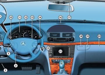
The button is located in the lower section of the center console.
1 Vehicle level control button 2 Indicator lamp 왘 Start the engine (컄 page 36). 왘 Briefly press button 1 to change from normal level to raised level. When vehi- cle is at raised level, pressing the but- ton will return the vehicle to normal level. When raised level is set, indicator lamp 2 in the button comes on. When normal level is set, indicator lamp 2 in the button goes out.
Controls in detail Driving systems
Parktronic system (Parking assist)*
Warning!
Parktronic is a supplemental system. It is not intended to, nor does it replace, the need for extreme care. The responsibility during parking and other critical maneuvers always rests with the driver.
Special attention must be paid to objects with smooth surfaces or low silhouettes (e.g. trailer couplings, painted posts, or road curbs). Such objects may not be detected by the system and can damage the vehicle.
The operational function of the Parktronic system can be affected by dirty sensors, es- pecially at times of snow and ice, see “Cleaning the Parktronic system* sensors” (컄 page 368). Interference caused by other ultrasonic sig- nals (e.g. working jackhammers, car wash or the air brakes of trucks) can cause the sys- tem to send erratic indications, and should be taken into consideration.
263
Controls in detail Driving systems
Warning!
Make sure no persons or animals are in the area in which you are maneuvering. You could otherwise injure them.
The Parktronic system is an electronic aid designed to assist the driver during park- ing maneuvers. It visually and audibly indi- cates the relative distance between the vehicle and an obstacle. The Parktronic system is automatically ac- tivated when you switch on the ignition, re- lease the parking brake, and placed the gear selector lever in position D, R, or N. The Parktronic system deactivates at speeds over approximately 11 mph (18 km/h). At lower speeds the Parktronic system turns on again. The Parktronic system also deactivates when you place the gear selector lever in position P or depress the parking brake pedal.
264
The Parktronic system monitors the sur- roundings of your vehicle with six sensors in the front bumper and four sensors in the rear bumper.
1 Sensors in the front bumper
Range of the sensors To function properly, the sensors must be free of dirt, ice, snow and slush. Clean the sensors regularly, being careful not to scratch or damage the sensors, see “Cleaning the Parktronic system* sensors” (컄 page 368).
Front sensors
Minimum distance
Center Corners
approx. 40 in (100 cm) approx. 24 in (60 cm)
Center Corners
approx. 8 in (20 cm) approx. 6 in (15 cm)
If the system detects an obstacle in this range, all the distance warning segments illuminate and you hear a warning signal. If the obstacle is closer than the minimum distance, the actual distance might no longer be indicated by the system.
Rear sensors
Center Corners
approx. 48 in (120 cm) approx. 32 in (80 cm)
During parking maneuvers, pay special attention to objects located above or below the height of the sensors (e.g. planters or trailer hitches). The Parktronic system will not detect such objects at close range and damage to your vehicle or the object may result. Ultrasonic signals from outside sourc- es (e.g. truck air brakes, car wash or jackhammers) may impair the opera- tion of the Parktronic system.
Controls in detail Driving systems
Warning indicators Visual signals indicate to the driver the rel- ative distance between the sensors and an obstacle. The warning indicator for the front area is located above the center air vents in the dashboard. The warning indi- cator for the rear area is integrated in the rear trim.
Front area warning indicator 1 Left side of the vehicle 2 Right side of the vehicle 3 Readiness indicators
265
Controls in detail Driving systems
Each warning indicator is divided into five yellow and two red segments for either side of the vehicle. The Parktronic system is operational when the yellow readiness indicators 3 are illuminated. The position of the gear selector lever de- termines which warning indicators will be activated.
Gear selector lever position R or N
Warning indicator
Front area activated Front and rear area activated Neither activated
As your vehicle approaches an object, one or more segments will come on, depending on the distance. When the seventh seg- ment illuminates, you have reached the minimum distance.
266
앫 Front area: An intermittent acoustic
warning will sound as the first red dis- tance segment illuminates and a con- stant acoustic warning lasting a maximum of 2 seconds will sound for the second red distance segment. The signal is canceled when the gear selec- tor lever is placed in position P or the parking brake is activated.
앫 Rear area: An intermittent acoustic
warning will sound as the first red dis- tance segment illuminates and a con- stant acoustic warning lasting a maximum of 2 seconds will sound for the second red distance segment. The signal is canceled when the gear selec- tor lever is placed in position D, P or the parking brake is activated.
Switching the Parktronic system on/off The Parktronic system can be switched off manually. The Parktronic switch is located in the low- er part of the center console (컄 page 28).
1 Parktronic switch 2 Indicator lamp
If only the red distance segments illumi- nates and no acoustic warning sounds, the Parktronic system sensors are dirty or there is an interference from other radio or ultrasonic signals. The Parktronic system will automatically switch off after 20 sec- onds and the indicator lamp in the Park- tronic switch comes on. 왘 Switch off the ignition (컄 page 36). 왘 Clean the Parktronic system sensors
(컄 page 368).
왘 Switch on the ignition (컄 page 36).
or
왘 Check the Parktronic system operation at another location to rule out interfer- ence from outside radio or ultrasonic signals.
Switching off the Parktronic system 왘 Press Parktronic switch 1. Indicator lamp 2 comes on.
Switching on the Parktronic system 왘 Press Parktronic switch 1 again.
Indicator lamp 2 goes out.
The Parktronic system is automatically switched on when the ignition is switched on (컄 page 36).
Parktronic system malfunction If only the red distance segments illumi- nates and an acoustic warning sounds, there is a malfunction in the Parktronic system. The Parktronic system will auto- matically switch off after 20 seconds and the indicator lamp in the Parktronic switch comes on. 왘 Have the Parktronic system checked by an authorized Mercedes-Benz Cen- ter as soon as possible.
Controls in detail Driving systems
267
Preparing roof rack installation 왘 Open trim 1 at the trim strips in the
Ski sack*
roof.
왘 Secure the roof rack according to man- ufacturer’s instructions for installation.
Load the roof rack in such a way that the vehicle cannot be damaged while driving. Make sure 앫 you can fully raise the tilt/sliding
sunroof* or tilt/sliding panel*
앫 you can fully open the trunk
Unfolding and loading 왘 Fold rear armrest down (arrow). 왘 Swing cover 1 down.
Controls in detail Loading
Roof rack*
Warning!
Only use roof racks approved by Mercedes-Benz for your vehicle model to avoid damage to the vehicle. Follow manu- facturer’s installation instructions.
1 Trim
268
Controls in detail Loading
왘 Open hook and loop strap 1. 왘 Pull ski sack into passenger compart-
ment and unfold.
왘 From trunk, slide skis into ski sack.
왘 Wrap strap around ski sack and rear
Warning!
armrest.
왘 Close clasp (arrows) and pull strap
tight to firmly secure skis.
컄컄
The ski sack is designed for up to four pairs of skis. Do not load the ski sack with other objects.
Always fasten the ski sack securely. In an accident, an unfastened ski sack can cause injury to vehicle occupants.
269
Controls in detail Loading
컄컄
Unloading and folding
왘 Connect snap hook 1 of front strap to
eye 2 located on center tunnel in front of rear seat bench.
왘 Loosen strap, open clasp by pressing
tabs together (arrows).
왘 Unload skis. 왘 Close flap in trunk. 왘 Fold and flatten ski sack lengthwise
and place folded ski sack inside recess of backrest.
왘 Close ski sack compartment cover.
270
Removal of ski sack For removal of the ski sack, we recom- mend that you contact an authorized Mercedes-Benz Center.
Warning!
Never drive vehicle with trunk open while the ski sack is removed. Deadly carbon monoxide (CO) gases may enter vehicle in- terior, resulting in unconsciousness and death.
To prevent unauthorized persons from access to the trunk, always close the cover.
Controls in detail Loading
Split rear bench seat*
Folding the backrest forward
To expand the trunk, you can fold down the left and right rear seat backrests. The two sections can be folded down sep- arately to enlarge the trunk.
Warning!
When expanding the luggage compartment, always fold the seat cushions fully forward.
Unless you are transporting cargo, the back- rests must remain properly locked in the up- right position.
In an accident, during hard braking or sud- den maneuvers, loose items will be thrown around inside the vehicle, and cause injury to vehicle occupants unless the items are securely fastened in the vehicle.
Always use the cargo tie down rings (컄 page 275).
You must always release the seat cush- ion and fold it up before folding the seat backrests forward. The upholstery on the seat backrest may otherwise be damaged.
1 Release handle
271
Controls in detail Loading
If tall persons have occupied the driv- er’s and front passenger seats, it may be necessary to move these seats for- ward slightly in order to fold the rear seat backrests forward.
왘 Push the rear seat head restraints all
the way in.
If the rear center seat is to be occupied while driving, it may be necessary to fold the seat belt buckle up again.
왘 Pull release handle 1.
The seat cushion automatically springs upward slightly.
Make sure the head restraints fit all the way into the seat cushion pockets. This will prevent the backrests from being damaged during loading.
Returning seat backrest to original po- sition
왘 Pull the handle in the trunk.
The seat backrest is released and the head restraints fold back.
왘 Fold the seat backrest forward.
1 Seat cushion 2 Seat backrest 왘 Swing seat backrest 2 to the rear until
it engages.
왘 Swing seat cushion 1 to the rear and press the center front of the cushion until it audibly engages.
1 Seat cushion 2 Seat backrest 왘 Grip the back of seat cushion 1 and
fold forward.
272
Controls in detail Loading
Warning!
Expanding the cargo area*
왘 Swing the head restraint forward by
hand until it engages.
Always lock backrest in its upright position when rear seat bench is occupied, or the ex- tended trunk compartment is not in use. Check for secure locking by pushing and pulling on the backrest.
In an accident, during hard braking or sud- den maneuvers, loose items will be thrown around inside the vehicle, and cause injury to vehicle occupants unless the items are securely fastened in the vehicle.
To help avoid personal injury during a colli- sion or sudden maneuver, exercise care when transporting cargo.
Removing the rear seat cushions will pro- vide you with a larger, flat cargo area. 왘 Fold the seat cushions and the back-
rests forward (컄 page 271). 왘 Remove the head restraints
(컄 page 133).
왘 Fold the backrest into the vertical posi-
tion.
1 Release lever 왘 Pull seat cushion release lever 1 and remove the seat cushion by pulling it upward.
컄컄
273
Controls in detail Loading
컄컄
Leave the seat cushion hinge in this po- sition. The upholstery could be dam- aged if you fold the hinge back.
Loading instructions
왘 Fold the seat backrest forward.
The total load weight including vehicle oc- cupants and luggage/cargo should not ex- ceed the load limit or vehicle capacity weight indicated on the corresponding placard located on the driver’s door B-pil- lar.
The handling characteristics of a fully load- ed vehicle depend greatly on the load dis- tribution. It is therefore recommended to load the vehicle according to the illustra- tions shown, with the heaviest items being placed towards the front of the vehicle. Always place items being carried against front or rear seat backrests, and fasten them as securely as possible. The heaviest portion of the cargo should al- ways be kept as low as possible since it in- fluences the handling characteristics of the vehicle.
274
Warning!
Cargo tie-down rings*
Always fasten items being carried as secure- ly as possible.
In an accident, during hard braking or sud- den maneuvers, loose items will be thrown around inside the vehicle and can cause in- jury to vehicle occupants unless the items are securely fastened in the vehicle.
To help avoid personal injury during a colli- sion or sudden maneuver, exercise care when transporting cargo. Put luggage or car- go in the trunk if possible. Do not pile lug- gage or cargo higher than the seat backs. Do not place anything on the rear-window shelf.
Never drive vehicle with trunk open. Deadly carbon monoxide (CO) gases may enter ve- hicle interior resulting in unconsciousness and death.
Four rings 1 are located in the trunk. 왘 Carefully secure cargo by applying
even load on all rings with rope of suffi- cient strength to hold down the cargo. Always follow loading instructions (컄 page 274).
Controls in detail Loading
Rear seat There is a cargo tie-down ring located on each side of the footwell under the rear seat.
275
Controls in detail Useful features
Storage compartments
Glove box
Storage compartment in the center console (no CD changer* installed)
Warning!
To help avoid personal injury during a colli- sion or sudden maneuver, exercise care when storing objects in the vehicle. Put lug- gage or cargo in the trunk if possible. Do not pile luggage or cargo higher than the seat backs. Do not place anything on the shelf below the rear window.
Luggage nets cannot secure hard or heavy objects.
Keep compartment lids closed. This will help to prevent stored objects from being thrown around and injuring vehicle occupants dur- ing an accident.
276
1 Glove box lid release 2 Compartment for mobile phone/glass-
es
1 Opening/closing button 왘 Press button 1 to open.
Opening the glove box 왘 Push glove box lid release 1.
The glove box lid opens downward.
Closing the glove box 왘 Push glove box lid up to close.
Close the compartment for glasses 2 first before closing the glove box.
The control panel swings out upward and the storage compartment extends out.
Never place any medications in the storage compartment. If there is a pow- er failure, the storage compartment cannot be opened.
왘 Press button 1 to close.
Storage compartment in the rear cen- ter console
Ruffled storage bags
왘 Briefly press the top of the compart-
ment. It extends automatically.
Ruffled storage bags are located on the back of the front seats.
Controls in detail Useful features
Warning!
Do not place objects with a combined weight of more than 4.4 lbs (2 kg) into the ruffled storage bag. Otherwise, the Occu- pant Classification System OCS (컄 page 81) may not be able to properly approximate the occupant weight category.
The ruffled storage bag is intended for stor- ing light-weight items only.
Heavy objects, objects with sharp edges or fragile objects may not be transported in the ruffled storage bag. In an accident, during hard braking, or sudden maneuvers, they could be thrown around inside the vehicle and cause injury to vehicle occupants.
The ruffled storage bag cannot protect transported goods in the event of an acci- dent.
277
Controls in detail Useful features
Parcel net in front passenger footwell
Warning!
Cup holders
The parcel net is intended for storing light-weight items only.
Heavy objects, objects with sharp edges or fragile objects may not be transported in the parcel net. In an accident, during hard brak- ing, or sudden maneuvers, they could be thrown around inside the vehicle and cause injury to vehicle occupants.
The parcel net cannot protect transported goods in the event of an accident.
A small convenience parcel net is located in the front passenger footwell. It is for small and light items, such as road maps, mail, etc.
Warning!
In order to help prevent spilling liquids on vehicle occupants and/or vehicle equip- ment, only use containers that fit into the cup holder. Use lids on open containers and do not fill containers to a height where the contents, especially hot liquids, could spill during braking, vehicle maneuvers, or in an accident. Liquids spilled on vehicle occu- pants may cause serious personal injury. Liquids spilled on vehicle equipment may cause damage not covered by the Mercedes-Benz Limited Warranty.
When not in use, keep the cup holder closed. An open cup holder may cause injury to you or others when contacted during braking, vehicle maneuvers, or in an acci- dent.
278
Keep in mind that objects placed in the cup holder may come loose during braking, vehi- cle maneuvers, or in an accident and be thrown around in the vehicle interior. Ob- jects thrown around in the vehicle interior may cause an accident and/or serious per- sonal injury.
Storage compartment with cup holder in the center armrest The storage compartment in the center armrest contains a removable dual cup holder.
Opening storage compartment
1 Cover 왘 Slide cover 1 in direction of arrow.
Controls in detail Useful features
2 Dual cup holder 3 Telephone* compartment
Closing storage compartment 왘 Slide cover 1 back.
The cup holder can be removed to in- crease storage space and for cleaning. Clean the cup holder only with clear, lukewarm water. Make sure to insert the cup holder in the guides when reinstalling it (컄 page 280).
279
Controls in detail Useful features
Removing cup holder
Reinstalling cup holder
Rear cup holder
1 Dual cup holder 2 Locking pins 왘 Move both locking pins 2 in direction
of arrows.
왘 Take cup holder 1 out upward.
3 Locking pins 왘 Insert cup holder. 왘 Move both locking pins 3 in direction
of arrows.
왘 Briefly press the front of the rear arm-
rest. The cup holder extends automatically.
280
Ashtrays
Removing ashtray insert
Center console ashtray
Warning!
Reinstalling ashtray insert 왘 Install insert by pushing it back into
frame until it engages again.
Controls in detail Useful features
Remove front ashtray only with vehicle standing still. Set the parking brake to se- cure vehicle from movement. Move gear se- lector lever to position N. With gear selector lever in position N, turn off the engine.
왘 Secure vehicle from movement by set- ting the parking brake. Move the gear selector lever to position N. Now you have more room to take out the insert.
왘 Push sliding button 2 to the right and
hold.
Rear seat ashtray
Opening rear seat ashtray 왘 Briefly press the top of the ashtray.
왘 Grip and remove insert from ashtray
The cover opens automatically.
frame.
Opening ashtray 왘 Briefly press the marking on the bot-
tom of cover 1. The cover opens automatically.
281
Controls in detail Useful features
Cigarette lighter
Warning!
Never touch the heating element or sides of the lighter; they are extremely hot. Hold the knob only.
When leaving the vehicle, always remove the SmartKey or the SmartKey with KEYLESS-GO* from the starter switch, take it with you, and lock the vehicle. Do not leave children unattended in the vehicle, or with access to an unlocked vehicle. Unsu- pervised use of vehicle equipment may cause an accident and/or serious personal injury.
282
The cigarette lighter is located in the cen- ter console compartment in front of the center armrest (컄 page 28).
1 Cigarette lighter 왘 Switch on the ignition (컄 page 36). 왘 Push in cigarette lighter 1.
The lighter will pop out automatically when hot.
The lighter socket can be used to ac- commodate 12V DC electrical acces- sories (up to a maximum of 85 W) designed for use with the standard “cigarette lighter” plug type. Keep in mind, however, that connecting acces- sories to the lighter socket (for exam- ple extensive connecting and disconnecting, or using plugs that do not fit properly) can damage the lighter socket. With the socket damaged, the lighter may no longer be able to be placed in the heating (pushed-in) posi- tion, or the lighter may pop out too ear- ly with the lighter not hot enough. To help avoid damaging the cigarette lighter socket, we recommend con- necting 12V DC electrical accessories designed for use with a standard “ciga- rette lighter” plug type to the 12V pow- er outlets in your vehicle whenever possible.
Power outlet
Heated steering wheel*
The power outlet is located in the rear pas- senger compartment.
The steering wheel heating warms up the leather area of the steering wheel. The stalk is on the lower left-hand side of the steering wheel.
왘 Switch on the ignition (컄 page 36). 왘 Flip up cover and insert electrical plug
(cigarette lighter type).
The power outlet can be used to accommodate 12V DC electrical ac- cessories (e.g. air pump, auxiliary lamps) up to a maximum of 180 W. An additional power outlet is located on the left side in the trunk.
1 Indicator lamp 2 Switching off 3 Switching on
Controls in detail Useful features
Switching on 왘 Switch on the ignition (컄 page 36). 왘 Turn switch at the tip of stalk in direc-
tion of arrow 3. The steering wheel is heated. Indicator lamp 1 comes on.
The steering wheel heating is tempo- rarily suspended while indicator lamp 1 remains on when 앫 the temperature of the vehicle inte-
rior is above 86°F (30°C)
앫 the temperature of the steering
wheel is above 95°F (35°C)
When these conditions do not apply anymore, steering wheel heating con- tinues.
283
Floormats
Controls in detail Useful features
Switching off 왘 Turn switch at the tip of stalk in direc-
tion of arrow 2. The heated steering wheel is switched off. Indicator lamp 1 goes out.
Indicator lamp 1 flashes or goes out 앫 in case of power surge or undervolt-
age
앫 in case of a steering wheel heating
malfunction
1 Retainer pin 2 Eyelet
To install or remove the floormat more easily, move the driver’s seat or front passenger seat as far to the rear as possible (컄 page 41).
The steering wheel heating switches off automatically when you remove the SmartKey from the starter switch or, on vehicles with KEYLESS-GO*, when you switch off the ignition (컄 page 62) and open the driver’s door.
For information on steering wheel, see “Multifunction steering wheel” (컄 page 154).
284
Warning!
Whenever you are using floormats, make sure there is enough clearance and that the floormats are securely fastened.
Floormats should always be securely fas- tened using eyelets 2 and retainer pins 1. Before driving off, check that the floormats are securely in place and adjust them if nec- essary. A loose floormat could slip and hinder proper functioning of the pedals.
Removing 왘 Pull floormat off of retainer pins 1. 왘 Remove the floormat.
Installing 왘 Lay down the floormat. 왘 Press the floormat eyelets 2 onto re-
tainer pins 1.
Telephone*
Warning!
Never operate radio transmitters equipped with a built-in or attached antenna (i.e. with- out being connected to an external antenna) from inside the vehicle while the engine is running. Doing so could lead to a malfunc- tion of the vehicle’s electronic system, pos- sibly resulting in an accident and/or serious personal injury.
Radio transmitters, such as a portable tele- phone or a citizens band unit, should only be used inside the vehicle if they are con- nected to an antenna that is installed on the outside of the vehicle. The external antenna must be approved by Mercedes-Benz. Please contact an autho- rized Mercedes-Benz Center for informa- tion on the installation of an approved external antenna. Refer to the radio trans- mitter operation instructions regarding use of an external antenna.
Warning!
Please do not forget that your primary re- sponsibility is to drive the vehicle. A driver’s attention to the road must always be his/her primary focus when driving. For your safety and the safety of others, we rec- ommend that you pull over to a safe location and stop before placing or taking a tele- phone call. If you choose to use the telephone1 while driving, please use the hands-free device and only use the telephone when road, weather and traffic conditions permit. Some jurisdictions prohibit the driver from using a cellular telephone while driving a vehicle.
Only operate the COMAND (Cockpit Man- agement and Data System) if road, weather and traffic conditions permit.
1 Observe all legal requirements.
Controls in detail Useful features
Bear in mind that at a speed of just 30 mph (approximately 50 km/h), your vehicle is covering a distance of 44 feet (approximate- ly 14 m) every second.
You can take and place telephone calls us- ing buttons s and t on the steering wheel. To carry out other telephone func- tions, use the control system (컄 page 180). See separate operating manual for instruc- tions on how to use the telephone.
285
Controls in detail Useful features
Tele Aid
The initial activation of the Tele Aid sys- tem may only be performed by com- pleting the subscriber agreement and placing an acquaintance call using button ¡. Failure to complete either of these steps will result in a system that is not activated. If you have any questions regarding ac- tivation, please call the Response Cen- ter at 1-800-756-9018 (in the USA) or 1-888-923-8367 (in Canada).
Shortly after the completion of your Tele Aid acquaintance call, you will receive a user ID and password. By visiting www.mbusa.com and selecting “Tele Aid” (USA only), you will have access to account information, remote door unlock and more.
286
The Tele Aid system (Telematic Alarm Identification on De- mand) The Tele Aid system consists of three types of response: 앫 automatic and manual emergency 앫 Roadside Assistance and 앫 information The Tele Aid system is operational provid- ing that the vehicle’s battery is charged, properly connected, not damaged and cel- lular and GPS coverage is available. The speaker volume of a Tele Aid call can be adjusted when using the volume control on the multifunction steering wheel. To raise, press button æ and to lower, press button ç or use the volume knob on your COMAND headunit. 왘 To activate, press the SOS button, the
Roadside Assistance button • or the Information button ¡, depend- ing on the type of response required.
The SOS button is located above the in- terior rear view mirror. The Roadside Assistance button • and the Information button ¡ are located below the center armrest cov- er.
The Tele Aid system utilizes the cellular network for communication and the GPS (Global Positioning System) satel- lites for vehicle location. If either of these signals are unavailable, the Tele Aid system may not function and if this occurs, assistance must be sum- moned by other means.
System self-check Initially, after switching on the ignition, malfunctions are detected and indicated (the indicator lamps in the SOS button, the Roadside Assistance button • and the Information button ¡ stay on longer
than 10 seconds or do not come on). The message Tele Aid malfunction Drive to workshop appears in the multi- function display.
Warning!
If the indicator lamps in the SOS button, in the Roadside Assistance button and/or in the Information button remain illuminated constantly in red and/or the message Tele Aid malfunction Drive to workshop is displayed in the multifunction display after the system self-check, a mal- function in the system has been detected.
If a malfunction is indicated as outlined above, the system may not operate as ex- pected. Have the system checked at the nearest Mercedes-Benz Center as soon as possible.
Emergency calls An emergency call is initiated automatical- ly following an accident in which the emer- gency tensioning devices (ETDs) or air bags deploy. An emergency call can also be initiated manually by opening the cover next to the interior rear view mirror labeled SOS, then briefly pressing the button located under the cover. See (컄 page 288) for instruc- tions on initiating an emergency call man- ually. Once the emergency call is in progress, the indicator lamp in the SOS button will begin to flash. The message Connecting call appears in the multifunction display and the audio system is muted. When the con- nection is established, the message Call connected appears in the multifunc- tion display. All information relevant to the emergency, such as the location of the ve- hicle (determined by the GPS satellite loca- tion system), vehicle model, identification number and color are generated.
Controls in detail Useful features
A voice connection between the Response Center and the occupants of the vehicle will be established automatically soon af- ter the emergency call has been initiated. The Response Center will attempt to deter- mine more precisely the nature of the emergency provided they can speak to an occupant of the vehicle.
287
Controls in detail Useful features
The Tele Aid system is available if 앫 it has been activated and is operation- al. Activation requires a subscription for monitoring services, connection and cellular air time
앫 the relevant cellular phone network
and GPS signals are available and pass the information on to the Response Center
Location of the vehicle on a map is only possible if the vehicle is able to receive signals from the GPS satellite network and pass the information on to the Response Center.
Warning!
If the indicator lamp in the SOS button is flashing continuously and there was no voice connection to the Response Center established, then the Tele Aid system could not initiate an emergency call (e.g. the rele- vant cellular phone network is not available). The message Call failed appears in the multifunction display for approximately 10 seconds.
Should this occur, assistance must be sum- moned by other means.
288
Initiating an emergency call manually
1 Cover 2 SOS button 왘 Briefly press on cover 1.
The cover will open.
왘 Press SOS button 2 briefly.
The indicator lamp in SOS button 2 will flash until the emergency call is concluded.
왘 Wait for a voice connection to the Re-
sponse Center.
왘 Close cover after the emergency call is
concluded.
Warning!
If you feel at any way in jeopardy when in the vehicle (e.g. smoke or fire in the vehicle, ve- hicle in a dangerous road location), please do not wait for voice contact after you have pressed the emergency button. Carefully leave the vehicle and move to a safe loca- tion. The Response Center will automatically contact local emergency officials with the vehicle’s approximate location if they re- ceive an automatic SOS signal and cannot make voice contact with the vehicle occu- pants.
Roadside Assistance button • Located below the center armrest cover is the Roadside Assistance button •. 왘 Press and hold the button (for longer
than 2 seconds). A call to a Mercedes-Benz Roadside As- sistance dispatcher will be initiated. The button will flash while the call is in progress. The message Connecting call will appear in the multifunction display and the audio system is muted.
When the connection is established, the message Call connected appears in the multifunction display. The Tele Aid system will transmit data generating the vehicle identification number, model, color and lo- cation (subject to availability of cellular and GPS signals). A voice connection between the Roadside Assistance dispatcher and the occupants of the vehicle will be established. 왘 Describe the nature of the need for as-
sistance.
Controls in detail Useful features
The Mercedes-Benz Roadside Assistance dispatcher will either dispatch a qualified Mercedes-Benz technician or arrange to tow your vehicle to the nearest authorized Mercedes-Benz Center. For services such as labor and/or towing, charges may ap- ply. Refer to the Roadside Assistance man- ual for more information. The following is only available in the USA: 앫 Sign and Drive services: Services such as a jump start, a few gallons of fuel or the replacement of a flat tire with the vehicle spare tire are obtainable.
289
Controls in detail Useful features
The indicator lamp on the Roadside As- sistance button • remains illumi- nated in red for approximately 10 seconds during the system self-check after switching on the igni- tion (together with the SOS button and the Information button ¡). See system self-check (컄 page 286) when the indicator lamp does not come on in red or stays on longer than ap- proximately 10 seconds. If the indicator lamp on the Roadside Assistance button • is flashing con- tinuously and there was no voice con- nection to the Response Center established, then the Tele Aid system could not initiate a Roadside Assis- tance call (e.g. the relevant cellular phone network is not available). The message Call failed appears in the multifunction display.
Roadside Assistance calls can be ter- minated using button t on the mul- tifunction steering wheel or the respective button for ending a tele- phone call on the COMAND headunit.
Information button ¡ The Information button ¡ is located be- low the center armrest cover. 왘 Press and hold button (for longer than
2 seconds). A call to the Customer Assistance Cen- ter will be initiated. The button will flash while the call is in progress. The message Connecting call will appear in the multifunction display and the au- dio system is muted.
When the connection is established, the message Call connected appears in the multifunction display. The Tele Aid system will transmit data generating the vehicle identification number, model, color and lo- cation (subject to availability of cellular and GPS signals).
A voice connection between the Customer Assistance Center representative and the occupants of the vehicle will be estab- lished. Information regarding the operation of your vehicle, the nearest authorized Mercedes-Benz Center or Mercedes-Benz USA products and services is available to you. For more details concerning the Tele Aid system, please visit www.mbusa.com and use your ID and password (sent to you sep- arately) to learn more (USA only).
The indicator lamp on the Information button ¡ remains illuminated in red for approximately 10 seconds during the system self-check after switching on the ignition (together with the SOS button and the Roadside Assistance button •).
290
! If the indicator lamps do not start flash- ing after pressing one of the buttons or remain illuminated (in red) at any time, the Tele Aid system has detected a malfunction or the service is not cur- rently active, and may not initiate a call. Visit an authorized Mercedes-Benz Center and have the system checked or contact the Response Center at 1-800-756-9018 (in the USA) or 1-888-923-8367 (in Canada) as soon as possible.
See system self-check (컄 page 286) when the indicator lamp does not come on in red or stays on longer than ap- proximately 10 seconds. If the indicator lamp on the Information button ¡ is flashing continuously and there was no voice connection to the Response Center established, then the Tele Aid system could not initiate an Information call (e.g. the relevant cellular phone network is not avail- able). The message Call failed ap- pears in the multifunction display. Information calls can be terminated us- ing button t on the multifunction steering wheel or the respective button for ending a telephone call on the COMAND headunit.
Controls in detail Useful features
Call priority If other service calls such as a Roadside Assistance call or Information call are active, an Emergency call is still possible. In this case, the Emergency call will take priority and override all other ac- tive calls.
The indicator lamp in the respective button flashes until the call is conclud- ed. Calls can only be terminated by a Response Center or Customer Assis- tance Center representative except Roadside Assistance and Information calls, which can also be terminated by pressing button t on the multifunc- tion steering wheel or the respective button for ending a telephone call on the COMAND headunit.
291
Controls in detail Useful features
If the indicator lamp continues to flash or the system does not reset, contact the Response Center at 1-800-756-9018 (in the USA) or 1-888-923-8367 (in Canada), or Mercedes-Benz Customer Assistance at 1-800-FOR-MERCedes (1-800-367-6372) in the USA or Cus- tomer Service at 1-800-387-0100 in Canada.
292
When a Tele Aid call has been initiated, the COMAND system audio is muted and the selected mode (radio or CD) pauses. The optional cellular phone (if installed) switches off. If you must use this phone, the vehicle must be parked. Disconnect the coiled cord and place the call. The COMAND navigation* system (if engaged) will continue to run. The multifunction display in the in- strument cluster is available for use, and spoken commands are only avail- able by pressing the RPT button on the COMAND unit. A pop-up window will appear in the COMAND display to indi- cate that a Tele Aid call is in progress.
Remote door unlock In case you have locked your vehicle unin- tentionally (e.g. SmartKey inside vehicle), and the reserve SmartKey is not handy: 왘 Contact the Mercedes-Benz Response Center at 1-800-756-9018 (in the USA) or 1-888-923-8367 (in Canada). You will be asked to provide your pass- word which you provided when you completed the subscriber agreement. 왘 Then return to your vehicle and pull the trunk recessed handle for a minimum of 20 seconds until the SOS button is flashing. The message Call connected appears in the multifunction display.
As an alternative, you may unlock the vehi- cle via Internet using the ID and password sent to you shortly after the completion of your acquaintance call. The Response Center will then unlock your vehicle with the remote door unlocking feature.
i The remote door unlock feature is avail- able if the relevant cellular phone net- work is available. The SOS button will flash and the mes- sage Call connected will appear in the multifunction display to indicate re- ceipt of the door unlock command. Once the vehicle is unlocked, a Re- sponse Center specialist will attempt to establish voice contact with the ve- hicle occupants. If the trunk recessed handle was pulled for more than 20 seconds before door unlock authorization was received by the Response Center, you must wait 15 minutes before pulling the trunk re- cessed handle again.
Stolen Vehicle Recovery services In the event your vehicle was stolen: 왘 Report the incident to the police.
The police will issue a numbered inci- dent report.
왘 Pass this number on to the
Mercedes-Benz Response Center along with your password issued to you when you subscribed to the service. The Response Center will then attempt to covertly contact the vehicle’s Tele Aid system. Once the vehicle is locat- ed, the Response Center will contact the local law enforcement and you. The vehicle’s location will only be provided to law enforcement.
When the anti-theft alarm or the tow-away alarm stays on for more than 30 seconds, a call is initiated automat- ically to the Response Center. See an- ti-theft alarm system (컄 page 101) and tow-away alarm (컄 page 103).
Controls in detail Useful features
Garage door opener
The integrated remote control is capable of operating up to three separately controlled devices. It provides a convenient way to re- place up to three hand-held remote con- trols used to operate devices such as garage door openers, gate openers, or oth- er devices compatible with HomeLink® or some other systems. Before the integrated remote control can be used, it must be programmed to the ga- rage door opener, gate operator or other device you wish to operate. See the follow- ing instructions for programming informa- tion.
293
Controls in detail Useful features
Indicator lamp
Interior rear view mirror with integrated re- mote control 2 3 4 Signal transmitter button Needed for programming (not part of vehi- cle equipment):
Hand-held remote control of ga- rage door opener, gate operator or other device Hand-held remote control but- ton
294
Warning!
When programming a garage door opener, park vehicle outside the garage.
Do not run the engine while programming the integrated remote control. Inhalation of exhaust gas is hazardous to your health. All exhaust gas contains carbon monoxide, and inhaling it can cause unconsciousness and possible death.
Programming the integrated remote control Step 1: 왘 Switch on the ignition (컄 page 36).
Before programming the integrated remote control to a garage door opener or gate operator, make sure people and objects are out of the way of the device to prevent po- tential harm or damage. When programming a garage door opener, the door moves up or down. When programming a gate operator, the gate opens or closes.
Do not use the integrated remote control