- 2011 Mercedes-Benz C Class Coupe Owners Manuals
- Mercedes-Benz C Class Coupe Owners Manuals
- 2005 Mercedes-Benz C Class Coupe Owners Manuals
- Mercedes-Benz C Class Coupe Owners Manuals
- 2003 Mercedes-Benz C Class Coupe Owners Manuals
- Mercedes-Benz C Class Coupe Owners Manuals
- 2004 Mercedes-Benz C Class Coupe Owners Manuals
- Mercedes-Benz C Class Coupe Owners Manuals
- 2002 Mercedes-Benz C Class Coupe Owners Manuals
- Mercedes-Benz C Class Coupe Owners Manuals
- 2013 Mercedes-Benz C Class Coupe Owners Manuals
- Mercedes-Benz C Class Coupe Owners Manuals
- Download PDF Manual
-
case, the brake system functions in the usual manner, but without antilock assistance. A malfunctioning ABS control unit can possibly affect the operation of other systems (e.g. Navigation, Automatic transmission). Be guided accordingly with respect to the use of those systems and have the system checked at your authorized Mercedes-Benz Center as soon as possible.
With the ABS malfunctioning, the BAS and ESP are also switched off. The malfunction indicator lamps and malfunction messages in the multifunction display come on with the engine running. If the charging voltage falls below 10 volts, the malfunction indicator lamp comes on and the ABS is switched off. When the voltage is above this value again, the malfunction indicator lamp should go out and the ABS is operational. Have the system checked at your authorized Mercedes-Benz Center as soon as possible. See page 272 for notes on antilock brake system (ABS).
Malfunction and indicator lamps
287
Instruments and controls
Operation
Driving
Instrument cluster display
Practical hints
Car care
Technical
data
Index
Instruments and controls
Operation
Driving
Instrument cluster display
Practical hints
Car care
Technical
data
Index
Malfunction and indicator lamps
288
Electronic stability program (ESP) — warning lamp
Seat belt nonusage warning lamp
The yellow ESP warning lamp in the speedometer dial comes on with the electronic key in starter switch position 2.
It should go out with engine running. If the ESP malfunction indicator lamp remains illuminated with the engine running, a malfunction has been detected in the system. Pressing the accelerator pedal will require greater effort. Only partial engine output will be available. See electronic stability program (ESP) on page 274 if the warning lamp lights up or flashes when the vehicle is moving.
With the electronic key in starter switch position 2, the seat belt nonusage warning lamp comes on, and a warning sounds for a
short time if the drivers seat belt is not fastened. After starting the engine, the seat belt nonusage warning lamp blinks for a brief period to remind the driver and passengers to fasten seat belts.
Malfunction and indicator lamp in the center console
AIRBAG OFF indicator lamp The ü indicator lamp will light up for approximately 6 seconds when you turn the electronic key in starter switch to position 1 or 2. It does not light up if there is a fault in the system. The ü indicator lamp stays lit as long as a Baby SmartTM child seat is properly installed on the front passenger seat. It indicates that the front passenger airbag is switched off. See page 69 for BabySmartTM airbag and its deactivation system.
Warning! The BabySmartTM airbag deactivation system will ONLY work with a special child seat designed to operate with it. It will not work with child seats which are not BabySmartTM compatible. Never place anything between seat cushion and child seat (e.g. pillow), since it reduces the effectiveness of the deactivation system. Follow the manufacturer’s instructions for installation of special child seats. The passenger front airbag will not deploy only if the ü indicator lamp remains illuminated. Please be sure to check the indicator every time you use the special system child seat. Should the light go out while the restraint is installed, please check installation. If the light remains out, do not use the BabySmartTM restraint to transport children on the front passenger seat until the system has been repaired.
Baby SmartTM is a trademark of Siemens Automotive Corp.
Malfunction and indicator lamps
289
Instruments and controls
Operation
Driving
Instrument cluster display
Practical hints
Car care
Technical
data
Index
Instruments and controls
Operation
Driving
Instrument cluster display
Practical hints
Car care
Technical
data
Index
Malfunction and warning messages
290
Malfunction and warning messages in the multifunction display Malfunction and warning messages for the following systems will be displayed immediately in the multifunction display. They are divided into three categories. Category C1: Messages of most immediate priority. These cannot be cleared from the instrument cluster using the reset knob on the instrument cluster (see page 99). Categories C2 and C3: Messages of less immediate priority. These can be cleared from the instrument cluster using the reset knob on the instrument cluster (see page 99) and are then stored in the malfunction message memory. See page 119.
Note: Certain malfunction and warning messages are accompanied by an audible signal. Malfunction and warning messages in red are always accompanied by an audible signal. Temporary messages such as “TRUNK OPEN!” will not be stored in the malfunction message memory.
Warning! All categories of messages contain important information which should be taken note of and, where malfunction indicated, addressed as soon as possible at an authorized Mercedes-Benz Center. Failure to repair condition noted may cause damage not covered by the Mercedes-Benz Limited Warranty, or result in property damage or personal injury.
DISPLAY DEFECTIVE (engine control unit)
DISPLAY DEFECTIVE (several systems)
Line 1
Line 2
VISIT WORKSHOP!
DISPLAY FAULTY
C*
Line 1
Line 2
VISIT WORKSHOP!
DISPLAY FAULTY
C*
* C = Category, see page 290
* C = Category, see page 290
This message is displayed to indicate that the information being relayed by the engine control unit is no longer complete. The display for coolant temperature gauge, tachometer, or the cruise control may have failed.
The displays for several systems have failed. Some systems themselves may also have failed.
Malfunction and warning messages
291
Instruments and controls
Operation
Driving
Instrument cluster display
Practical hints
Car care
Technical
data
Index
Instruments and controls
Operation
Driving
Instrument cluster display
Practical hints
Car care
Technical
data
Index
Malfunction and warning messages
292
BATTERY /ALTERNATOR
Line 1
Line 2
BATTERY/ALTERNATOR
VISIT WORKSHOP!
C*
* C = Category, see page 290
This message indicates a malfunction which must be repaired immediately. It may indicate that the poly-V-belt has broken. Should this condition occur, the poly-V-belt must be replaced before continuing to operate the vehicle. Otherwise, the engine will overheat due to an inoperative water pump which may result in damage to the engine. Do not continue to drive the vehicle with this message displayed. Doing so could result in serious engine damage that is not covered by the Mercedes-Benz Limited Warranty.
ANTILOCK BRAKE SYSTEM
BRAKE ASSIST
Line 1
Line 2
ABS SYSTEM
VISIT WORKSHOP!
DISPLAY DEFECTIVE
VISIT WORKSHOP!1
C*
Line 1
BRAKE ASSIST
BRAKE ASSIST
Line 2
NOT AVAILABLE!
VISIT WORKSHOP!
* C = Category, see page 290
See page 272 for notes on the antilock brake system (ABS).
1 The display or the system is malfunctioning
DISPLAY DEFECTIVE
VISIT WORKSHOP!
* C = Category, see page 290
A malfunction has been detected in the system. The brake system functions in the usual manner, but without brake assist system (BAS). See page 271 for notes on the brake assist system (BAS).
C*
Malfunction and warning messages
293
Instruments and controls
Operation
Driving
Instrument cluster display
Practical hints
Car care
Technical
data
Index
Instruments and controls
Operation
Driving
Instrument cluster display
Practical hints
Car care
Technical
data
Index
Malfunction and warning messages
294
BRAKE PAD WEAR
BRAKE FLUID
Line 1
Line 2
BRAKE PAD WEAR
VISIT WORKSHOP!
C*
Line 1
Line 2
BRAKE FLUID
VISIT WORKSHOP!
C*
* C = Category, see page 290
* C = Category, see page 290
When this message appears during braking, it indicates that the brake pads are worn down. Have the brake system checked at your authorized Mercedes-Benz Center as soon as possible.
Warning! Driving with this message displayed can result in an accident. Have your brake system checked immediately. Don’t add brake fluid before checking the brake system. Overfilling the brake fluid reservoir can result in spilling brake fluid on hot engine parts and the brake fluid catching fire. You can be seriously burned.
PARKING BRAKE
SEAT BELT SYSTEM
Line 1
Line 2
PARKING BRAKE
ENGAGE BRAKE!
PARKING BRAKE
RELEASE BRAKE!
C*
* C = Category, see page 290
Line 1
Line 2
SEAT BELT SYSTEM
VISIT WORKSHOP!
PASSENGER SEAT BELT
FASTEN SEAT BELT!
DRIVER SEAT BELT
FASTEN SEAT BELT!
C*
* C = Category, see page 290
Malfunction and warning messages
295
Instruments and controls
Operation
Driving
Instrument cluster display
Practical hints
Car care
Technical
data
Index
Instruments and controls
Operation
Driving
Instrument cluster display
Practical hints
Car care
Technical
data
Index
Malfunction and warning messages
296
ELEC. STABIL. PROG. (Electronic stability program)
1 The enhanced vehicle stability offered by ESP and the torque
reduction feature are unavailable.
2 This message may be displayed if the power supply was
interrupted (battery disconnected or empty). Synchronize ESP, see page 275
3 The system is temporarily unavailable. The reason could be that the self-diagnosis has not been completed. The display will clear itself after driving a short distance at more than 12 mph (2o km/h).
4 The system is unavailable due to low voltage, e.g. battery not being
charged.
5 A malfunction has been detected in the system. In case of ESP
malfunction the ESP warning lamp in the instrument cluster illuminates and the ESP switch in the center console does not function. If in addition the ABS is malfunctioning, only partial engine output will be available.
6 The display or the system is malfunctioning.
Line 1
Line 2
ELEC. STABIL. PROG.
NOT AVAILABLE!1, 2, 3, 4
ELEC. STABIL. PROG.
VISIT WORKSHOP!1, 5
DISPLAY DEFECTIVE
VISIT WORKSHOP!6
C*
* C = Category, see page 290
COOLANT (coolant level)
Line 1
COOLANT
Line 2
CHECK LEVEL!
C*
* C = Category, see page 290
The low engine coolant level warning should not be ignored. Extended driving with the symbol displayed may cause serious engine damage not covered by the Mercedes-Benz Limited Warranty. In cases of major or frequent minor coolant loss, have the cooling system checked at your authorized Mercedes-Benz Center as soon as possible.
Note: Do not drive without coolant in the cooling system. The engine will overheat causing major engine damage. Monitor the coolant temperature gauge while driving, see page 137. See page 319 for instructions on topping up the coolant.
When this message appears while driving, the coolant level has dropped below the required level. If no leaks are noticeable and the engine temperature does not increase, continue to drive to the nearest service station and have coolant added to the coolant system.
Warning! Do not spill antifreeze on hot engine parts. Antifreeze contains ethylene glycol which may burn if it comes into contact with hot engine parts. You can be seriously burned.
Malfunction and warning messages
297
Instruments and controls
Operation
Driving
Instrument cluster display
Practical hints
Car care
Technical
data
Index
Instruments and controls
Operation
Driving
Instrument cluster display
Practical hints
Car care
Technical
data
Index
Malfunction and warning messages
298
COOLANT (coolant temperature)
Line 1
COOLANT
COOLANT
Line 2
STOP, ENGINE OFF!1
VISIT WORKSHOP!2
C*
* C = Category, see page 290
1 This may indicate that the poly-V-belt has broken. Should this
condition occur, the poly-V-belt must be replaced before continuing to operate the vehicle. Otherwise, the engine will overheat due to an inoperative water pump which may result in damage to the engine. Do not continue to drive the vehicle with this message displayed. Doing so could result in serious engine damage that is not covered by the Mercedes-Benz Limited Warranty.
2 The cooling fan for the coolant is faulty. Observe the coolant
temperature gauge. See page 137
During severe operating conditions and stop-and-go city traffic, the coolant temperature may rise close to 120°C. The engine should not be operated with the coolant temperature above 120°C. Doing so may cause serious engine damage which is not covered by the Mercedes-Benz Limited Warranty.
Warning! Driving when your engine is badly overheated can cause some fluids which may have leaked into the engine compartment to catch fire. You could be seriously burned. Steam from an overheated engine can cause serious burns and can occur just by opening the engine hood. Stay away from the engine if you see or hear steam coming from it. Turn off the engine, get out of the vehicle and do not stand near the vehicle until it cools down.
ENGINE OIL LEVEL
Line 1
Line 2
ENGINE OIL LEVEL
CHECK LEVEL!1
ENGINE OIL LEVEL
STOP, ENGINE OFF!2
ENGINE OIL LEVEL
REDUCE OIL LEVEL13
ENGINE OIL
VISIT WORKSHOP!4
ENGINE OIL LEVEL
VISIT WORKSHOP!5
C*
* C = Category, see page 290.
1 The engine oil level must be checked immediately. See Engine oil
level indicator on page 141.
2 There is no oil in the engine. There is a danger of engine damage.
3 There is a risk of damaging the engine or catalytic converter. The engine oil level must be checked immediately. See Engine oil level indicator on page 141.
4 The engine oil level has dropped to a critical level.
Check the engine oil level immediately. See Engine oil level indicator on page 141 and check the engine for visible leakage (loss of oil). It may be that there is water in the engine oil. Have the engine oil checked.
5 The measuring system is malfunctioning.
When the “ENGINE OIL LEVEL – CHECK LEVEL!” message appears while the engine is running and at operating temperature, the engine oil level has dropped to approximately the minimum mark on the dipstick. When this occurs, the warning will first come on intermittently and then stay on if the oil level drops further. If no oil leaks are noted, continue to drive to the nearest service station where the engine oil should be topped to the “full” mark on the dipstick with an approved oil. The engine oil level warnings should not be ignored. Extended driving with the symbol displayed could result in serious engine damage that is not covered by the Mercedes-Benz Limited Warranty.
Malfunction and warning messages
299
Instruments and controls
Operation
Driving
Instrument cluster display
Practical hints
Car care
Technical
data
Index
Instruments and controls
Operation
Driving
Instrument cluster display
Practical hints
Car care
Technical
data
Index
Malfunction and warning messages
300
LIGHTING SYSTEM
Line 1
Line 2
C*
TURN SIGNAL F, R
CHECK LAMP!
BRAKE LIGHT2
VISIT WORKSHOP!
BRAKE LIGHT, L3
CHECK LAMP!
BRAKE LIGHT, R3
CHECK LAMP!
3RD STOP LAMP3
CHECK LAMP!
C*
HIGH BEAM, L
HIGH BEAM, R
CHECK LAMP!
CHECK LAMP!
LICENSE PLATE L, L
CHECK LAMP!
LICENSE PLATE L, R
CHECK LAMP!
LIGHTS
SWITCH OFF LIGHTS!
AUTOM. LIGHT ON
REMOVE KEY!
FRONT FOGLAMP, L
CHECK LAMP!
FRONT FOGLAMP, R
CHECK LAMP!
REAR FOGLAMP
CHECK LAMP!
Line 1
LOW BEAM,L
LOW BEAM,R
Line 2
CHECK LAMP!
CHECK LAMP!
DISPLAY DEFECTIVE
VISIT WORKSHOP!1
TURN SIGNAL, L
CHECK LAMP!
TURN SIGNAL, R
CHECK LAMP!
L. TURN SIG. RFLECTR
CHECK LAMP!
R. TURN SIG. RFLECTR
CHECK LAMP!
TURN SIGNAL F, L
CHECK LAMP!
Line 1
Line 2
C*
REAR FOGLAMP
SWITCH OFF SUBSTITUTE LAMP ON!4
REVERSE LIGHT, L
CHECK LAMP!
REVERSE LIGHT, R
CHECK LAMP!
TAIL LIGHT, L
TAIL LIGHT, R
SIDELIGHT, L
SIDELIGHT, R
CHECK LAMP! SUBSTITUTE LAMP ON!4
CHECK LAMP! SUBSTITUTE LAMP ON!4
CHECK LAMP! SUBSTITUTE LAMP ON!4
CHECK LAMP! SUBSTITUTE LAMP ON!4
In the case of bulb failures in certain lamps, other lamps will substitute. See page 345 for instructions on replacing bulbs.
* C = Category, see page 290
1 The display or the system is malfunctioning.
2 The brake lamps are switching on after a delay or are permanently
on – visit workshop immediately.
3 The brake lamp comprises several light emitting diodes. The
warning message will only appear if all light emitting diodes have stopped working.
4 Other bulbs will be brought into use as replacements when certain
lamps blow.
Malfunction and warning messages
301
Instruments and controls
Operation
Driving
Instrument cluster display
Practical hints
Car care
Technical
data
Index
Instruments and controls
Operation
Driving
Instrument cluster display
Practical hints
Car care
Technical
data
Index
Malfunction and warning messages
LAMP SENSOR
302
DOOR
Line 1
Line 2
LAMP SENSOR
VISIT WORKSHOP!
C*
Line 1
DOOR OPEN!
Line 2
* C = Category, see page 290
* C = Category, see page 290.
P54.30-5440-21
C*
The headlamps will be switched on automatically if the light sensor malfunctions. The individual setting menu “LIGHTING”, “LIGHT CIRCUIT HEADLAMP MODE” can be set to “MANUAL”. See page 128. It will then be possible to switch the headlamps on and off using the exterior lamp switch. See page 143 for notes on the exterior lamp switch.
TRUNK OPEN
HOOD
Line 1
TRUNK OPEN!
Line 2
C*
Line 1
HOOD OPEN!
Line 2
C*
* C = Category, see page 290
* C = Category, see page 290.
See page 315 for hood.
Malfunction and warning messages
303
Instruments and controls
Operation
Driving
Instrument cluster display
Practical hints
Car care
Technical
data
Index
Instruments and controls
Operation
Driving
Instrument cluster display
Practical hints
Car care
Technical
data
Index
Malfunction and warning messages
TELEPHONE – FUNCTION
304
TELE AID
Line 1
FUNCTION
Line 2
NOT AVAILABLE!
C*
Line 1
TELE AID
Line 2
VISIT WORKSHOP!1
C*
* C = Category, see page 290.
* C = Category, see page 290.
The display appears if button í or ì on the multifunction steering wheel is pressed and the vehicle is not equipped with a telephone.
1 The Tele Aid system consists of three types of response; automatic and manual emergency, roadside assistance and information. With this message displayed, one or more functions may not be available.
See page 228 for notes on the Tele Aid.
If a malfunction is indicated as outlined above, have the system checked at the nearest Mercedes-Benz Center as soon as possible.
WASHER FLUID
Line 1
Line 2
WASHER FLUID
CHECK LEVEL!
C*
* C = Category, see page 290.
When this message appears while the engine is running, the level of the reservoir has dropped to approximately 1/3 of the total volume. The reservoir should be refilled with the prescribed mixture of MB Windshield washer concentrate and water or the concentrate and commercially available premixed windshield washer solvent/antifreeze, depending on ambient temperature, at the next opportunity. The reservoir for the windshield and headlamp washer systems is located in the engine compartment. See windshield and headlamp washer system on page 320 for instructions on topping up the washer fluid.
Malfunction and warning messages
305
Instruments and controls
Operation
Driving
Instrument cluster display
Practical hints
Car care
Technical
data
Index
Instruments and controls
Operation
Driving
Instrument cluster display
Practical hints
Car care
Technical
data
Index
Malfunction and warning messages
RESTRAINT SYSTEM
306
KEY
Line 1
Line 2
RESTRAINT SYSTEM
VISIT WORKSHOP!
* C = Category, see page 290.
C*
Line 1
Line 2
REPLACE KEY1
VISIT WORKSHOP!
AUTOM. LIGHT ON
REMOVE KEY!
C*
See page 62 for notes on the seat belts, and page 72 for notes on the airbags.
* C = Category, see page 290.
1 Key needs possibly to be replaced.
FUEL RESERVE
UNDERVOLTAGE
Line 1
Line 2
RESERVE FUEL
VISIT FILLING STATION!
C*
Line 1
Line 2
UNDERVOLTAGE
ENGINE ON!
* C = Category, see page 290.
UNDERVOLTAGE
CONSUMER DEFECTIVE!
* C = Category, see page 290.
C*
Malfunction and warning messages
307
Instruments and controls
Operation
Driving
Instrument cluster display
Practical hints
Car care
Technical
data
Index
Instruments and controls
Operation
Driving
Instrument cluster display
Practical hints
Car care
Technical
data
Index
Malfunction and warning messages
308
STEERING WHEEL ADJUST
Line 1
Line 2
STEERING WHEEL ADJUST
LOCK!
C*
* C = Category, see page 290.
For locking the manual steering wheel adjustment, see page 87.
Practical hints
First aid kit...................................... 310
Stowing things in the vehicle ...... 311
Fuses................................................ 311
Hood................................................. 315
Automatic transmissionfluid level ................................... 317
Adding engine oil........................... 318
Coolant level ................................... 319
Adding coolant............................ 319Windshield and headlamp
washer system ........................... 320
Spare wheel, storage
compartment.............................. 321
Vehicle tools and air pump .......... 322
Vehicle jack .................................... 323
Wheels ............................................ 324
Tire replacement........................ 324
Rotating wheels ......................... 325
Spare wheel.................................... 326
Changing wheels........................... 327Inflating the collapsible spare tire..................................... 333
Storing spare wheel in wheel well................................... 334
Tire inflation pressure ................. 335
Battery............................................. 336
Jump starting.................................. 338Towing the vehicle......................... 341
Transmission selector lever, manually unlocking................... 344
Exterior lamps................................ 345
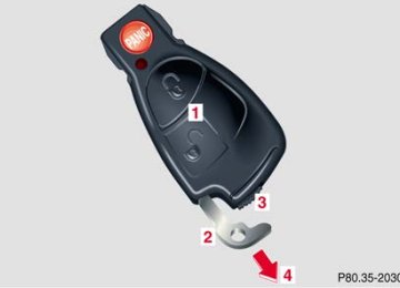
Replacing bulbs.......................... 345Changing batteries in the
electronic main key .................. 351
Synchronizing remote control.......................................... 353
Emergency engine shut-down ..... 353
Fuel filler flap, manual release ... 354
Replacing wiper blade insert....... 356
Roof rack ......................................... 357Contents - Practical hints
309
Instruments and controls
Operation
Driving
Instrument cluster display
Practical hints
Car care
Technical
data
Index
Instruments and controls
First aid kit
Operation
Driving
Instrument cluster display
Practical hints
Car care
Technical
data
Index
310
First aid kit
The first aid kit is located behind trim panel (1) in left hand side of trunk. To open: Turn handles (2) and remove trim panel (1).
Loosen securing strap (3) and remove first aid kit (4).
Note: Check contents of first aid kit for completeness on a regular basis.
Stowing things in the vehicle
Warning! To help avoid personal injury during a collision or sudden maneuver, exercise care when stowing things. Put luggage or cargo in the trunk if possible. Do not pile luggage or cargo higher than the seat backs. Do not place anything on the shelf below the rear window.
Fuses Most of your vehicle’s electrical components are fused with safety fuses. With the exception of the brake lights, all individual lighting system components are electronically fused. Before replacing a blown safety fuse, determine the cause of the short circuit. Always observe amperage and color of fuse. The circuit for components is protected by a cycled circuit breaker interrupted if too much current is being drawn. The circuit closes automatically after a short time; the circuit is broken again if the malfunction reoccurs. Always use a new fuse for replacement. Never attempt to repair or bridge a blown fuse. A fuse chart is located in fuse box (1). A special fuse puller is located in the auxiliary fuse box in the trunk, see page 314.
Fuses
Instruments and controls
Operation
Driving
Instrument cluster display
Practical hints
Car care
Technical
data
Index
311
Instruments and controls
Fuses
Operation
Driving
Instrument cluster display
Practical hints
Car care
Technical
data
Index
312
Fuse box in the passenger compartment
Fuse box in engine compartment
P54.15-2281-26
1 Fuse box in passenger compartment
To gain access to fuse box, pull cover away from fuse box (arrow) and remove rearward.
2 Cover 3 Screw 4 Retainer
To remove cover: Twist screws (3) 900 counterclockwise. Pull up cover (2), slide out retainer (4) and remove it by pulling cover towards front. Install in reverse order.
To gain access to fuse box: Release clamps (6) and remove the cover.
To close the fuse box: Ensure that the sealing rubber is properly positioned when you replace the cover. Press the cover down by hand and secure with clamps (6).
5 Fuse box in engine compartment, left-hand side 6 Clamps
Fuses
Instruments and controls
Operation
Driving
Instrument cluster display
Practical hints
Car care
Technical
data
Index
313
Instruments and controls
Fuses
Operation
Driving
Instrument cluster display
Practical hints
Car care
Technical
data
Index
314
Auxiliary fuse box in the trunk
7 Handles 8 Trim panel
Auxiliary fuse box (9) is located behind trim panel (8) in the left hand side of trunk. To open: Turn both handles (7) and remove trim panel (8).
9 Auxiliary fuse box
To close: Insert trim panel and turn both handles.
Note: The special fuse puller is located in the cover of the auxiliary fuse box.
The engine is equipped with a transistorized ignition system. Because of the high voltage it is dangerous to touch any components (ignition coils, spark plug sockets, diagnostic socket) of the ignition system
• with the engine running, • while starting the engine, • if ignition is “on” and the engine is turned
manually.
Hood
Warning! To help prevent personal injury, stay clear of moving parts when the hood is open and the engine is running. Be sure the hood is properly closed before driving. When closing hood, use extreme caution not to catch hands or fingers. The radiator fan may continue to run for approximately 30 seconds or even restart after the engine has been turned off. Stay clear from fan blades. If you see flames or smoke coming from the engine compartment, or if the coolant temperature gauge indicates that the engine is overheated, do not open the hood. Move away from vehicle and do not open the hood until the engine has cooled. If necessary, call a fire department.
Engine compartment
315
Instruments and controls
Operation
Driving
Instrument cluster display
Practical hints
Car care
Technical
data
Index
Instruments and controls
Operation
Driving
Instrument cluster display
Practical hints
Car care
Technical
data
Index
Engine compartment
316
To open: To unlock the hood, pull release lever (1) under the driver´s side of the instrument panel. At the same time a handle will extend out of the radiator grill.
Pull handle (2) to its stop out of radiator grill and open hood (do not pull up on the handle).
Note: To avoid damage to the windshield wipers or hood, open the hood only with the wipers in the parked position.
Automatic transmission fluid level The transmission has a permanent fill of automatic transmission fluid. Regular automatic transmission fluid level checks and changes are not required. For this reason the dipstick is omitted. If you notice fluid leaks or gear shifting malfunctions, have your authorized Mercedes-Benz Center check the transmission fluid level.
P88.40-2188-26
To close: Lower the hood and let it drop into lock from a height of approximately 1 ft. (30 cm), assisting with hands placed flat on edges of hood (3). To avoid hood damage, please make sure that hood is fully closed. If not, repeat closing procedure. Do not push down on hood to attempt to fully close it.
Engine compartment
317
Instruments and controls
Operation
Driving
Instrument cluster display
Practical hints
Car care
Technical
data
Index
Instruments and controls
Operation
Driving
Instrument cluster display
Practical hints
Car care
Technical
data
Index
Engine compartment
Adding engine oil
318
1 Oil dipstick 2 Oil filler cap
To check the engine oil level, park vehicle on level ground, with engine at normal operational temperature. Check engine oil level approximately 5 minutes after stopping the engine, allowing for the oil to return to the oil pan.
The engine oil level can be checked by either the oil dipstick or via the multifunction display in the instrument cluster. Wipe oil dipstick clean prior to checking the engine oil level. Fully insert dipstick in tube, and remove after three seconds to obtain accurate reading.
The oil level must be between the lower mark (min) and the upper mark (max) on the oil dipstick.
Fill quantity between upper and lower dipstick marking level is approximately 2.1 US qt (2.0 l). Do not overfill the engine. Excessive oil must be drained or siphoned. It could cause damage to engine and catalytic converter not covered by the Mercedes-Benz Limited Warranty. See malfunction and warning messages on page 290 if an engine oil level display appears on the multifunction display when the engine is running.
Note: See page 141 for engine oil level indicator display.
Coolant level
1 Coolant expansion tank
To check the coolant level, the vehicle must be parked on level ground and the engine stopped. Check coolant level only when coolant is cold. The coolant level should reach the black top part of the reservoir. See page 381 for antifreeze/anticorrosion mixture.
Adding coolant If coolant has to be added, a 50/50 mixture of water and MB anticorrosion/antifreeze should be added.
Warning!
• In order to avoid possibly serious burns:
Use extreme caution when opening the hood if there are any signs of steam or coolant leaking from the cooling system, or if the coolant temperature gauge indicates that the coolant is overheated.
• Do not remove pressure cap on coolant
reservoir if engine temperature is above 194°F (90°C). Allow engine to cool down before removing cap. The coolant reservoir contains hot fluid and is under pressure.
• Using a rag, slowly open cap approximately
1/2 turn to relieve excess pressure. If opened immediately, scalding hot fluid and steam will be blown out under pressure.
• Do not spill antifreeze on hot engine parts.
Antifreeze contains ethylene glycol which may burn if it comes into contact with hot engine parts.
Engine compartment
319
Instruments and controls
Operation
Driving
Instrument cluster display
Practical hints
Car care
Technical
data
Index
Instruments and controls
Operation
Driving
Instrument cluster display
Practical hints
Car care
Technical
data
Index
Engine compartment
320
Windshield and headlamp washer system
1 Windshield and headlamp washer fluid reservoir
The reservoir should be refilled with MB Windshield Washer Concentrate and water (or concentrate commercially available premixed windshield washer solvent/antifreeze, depending on ambient temperatures).
Vehicles without headlamp cleaning system: Capacity approximately 3.2 US qt (3.0 l) Vehicles with headlamp cleaning system: Capacity approximately 6.4 US qt (6.0 l)
Warning! Washer solvent/antifreeze is highly flammable. Do not spill washer solvent/antifreeze on hot engine parts, because it may burn. You can be seriously burned.
Windshield and headlamp washer fluid mixing ratio For temperatures above freezing: MB Windshield Washer Concentrate “S” and water. 1 part “S” to 100 parts water (40 ml “S” to 1 gallon water). For temperatures below freezing: MB Windshield Washer Concentrate “S” and commercially available premixed windshield washer solvent/antifreeze. 1 part “S” to 100 parts solvent (40 ml “S” to 1 gallon solvent).
Spare wheel, storage compartment
Lift trunk floor and engage handle in upper edge of trunk. Always lower trunk floor before closing trunk lid. To remove the spare wheel (1): Turn the mounting screw (3) counterclockwise and remove the spare wheel. To store spare wheel: Place spare wheel in wheel well and turn mounting screw (3) clockwise to its stop.
P68.00-2648-26
1 Spare wheel 2 Storage tray with vehicle tool kit, towing eye bolt,
wheel bolts and jack
3 Mounting screw for spare wheel/cover for vehicle
tools
Spare wheel
Instruments and controls
Operation
Driving
Instrument cluster display
Practical hints
Car care
Technical
data
Index
321
Instruments and controls
Spare wheel
Operation
Driving
Instrument cluster display
Practical hints
Car care
Technical
data
Index
Vehicle tools and air pump
Vehicle tools and air pump are located in the wheel well below the trunk floor.
P68.00-2708-26
322
1 Jack 2 Spare wheel bolts 3 Air pump 4 Towing eyes 5 Alignment pin 6 Wrench
To remove vehicle tools and air pump: Turn the mounting screw (3) counterclockwise, remove spare wheel and cover for vehicle tools, see page 321.
Vehicle jack
To prepare the jack for use: Remove the jack from the spare wheel well under the trunk floor. Push the crank handle up and turn clockwise until it engages (operational position).
Storing the jack in the trunk: Before storing the jack, it should be fully collapsed, with handle folded in (storage position).
Jack
Instruments and controls
Operation
Driving
Instrument cluster display
Practical hints
Car care
Technical
data
Index
323
Instruments and controls
Tires, Wheels
Operation
Driving
Instrument cluster display
Practical hints
Car care
Technical
data
Index
Warning! The jack is designed exclusively for jacking up the vehicle at the jack take-up brackets built into either side of the vehicle. To help avoid personal injury, use the jack only to lift the vehicle during a wheel change. Never get beneath the vehicle while it is supported by the jack. Keep hands and feet away from the area under the lifted vehicle. Always firmly set parking brake and block wheels before raising vehicle with jack. Do not disengage parking brake while the vehicle is raised. Be certain that the jack is always vertical when in use, especially on hills. Always try to use the jack on level surface. Be sure that the jack arm is fully seated in the jack take-up bracket. Always lower the vehicle onto sufficient capacity jackstands before working under the vehicle.
324
Wheels Replace rims or tires with the same designation, manufacturer and type as shown on the original part. See your authorized Mercedes-Benz Center for further information. See your authorized Mercedes-Benz Center for information on tested and recommended rims and tires for summer and winter operation. They can also offer advice concerning tire service and purchase.
Tire replacement Front and rear tires should be replaced in sets. Rims and tires must be of the correct size and type. For dimensions, see “Technical Data”. We recommend that you break in new tires for approximately 60 miles (100 km) at moderate speed.
It is imperative that the wheel mounting bolts be fastened to a tightening torque of 80 ft.lb. (110 Nm) whenever wheels are mounted. For rim and tire specifications, refer to “Technical Data”.
Warning! Worn, old tires can cause accidents. If the tire tread is badly worn, or if the tires have sustained damage, replace them. When replacing rims, use only genuine Mercedes-Benz wheel bolts specified for the particular rim type. Failure to do so can result in the bolts loosening and possibly an accident.
Rotating wheels The wheels can be rotated according to the degree of tire wear while retaining the same direction of travel. Rotating, however, should be carried out as recommended by the tire manufacturer, before the characteristic tire wear pattern (shoulder wear on front wheels and tread center wear on rear wheels) becomes visible, as otherwise the driving properties deteriorate.
Notes: Thoroughly clean the inner side of the wheels any time you rotate the wheels or wash the vehicle underside. The use of retread tires is not recommended. Retread tires may adversely affect the handling characteristics and safety of the vehicle. Dented or bent rims can cause tire pressure loss and damage to the tire beads. For this reason, check rims for damage at regular intervals. The rim flanges must be checked for wear before a tire is mounted. Remove burrs, if any. Check and ensure proper tire inflation pressure after rotating the wheels. For tire inflation pressure see inside of fuel filler flap and also page 278.
Tires, Wheels
Instruments and controls
Operation
Driving
Instrument cluster display
Practical hints
Car care
Technical
data
Index
325
Instruments and controls
Tires, Wheels
Operation
Driving
Instrument cluster display
Practical hints
Car care
Technical
data
Index
326
Spare wheel
Important! The spare wheel rim size is 4 1/2 B x 15 H 2 with inflatable, collapsible tire, size 165-15 89 P. You should inflate the spare tire using the supplied air pump.
Warning! The dimensions of the spare wheel are different from those of the road wheels. As a result, the vehicle handling characteristics change when driving with a mounted spare wheel. The spare wheel should only be used temporarily, and replaced with a regular road wheel as quick as possible.
In the case of a flat tire, you may temporarily use the spare wheel, while observing the following restrictions: • Do not exceed vehicle speed of 50 mph (80 km/h). • Drive to the nearest tire repair facility to have the
flat tire repaired or replaced as appropriate. • Do not operate vehicle with more than one
collapsible spare wheel/tire mounted.
For additional information, refer to page 374.
Changing wheels
Warning! The jack is designed exclusively for jacking up the vehicle at the jack take-up brackets built into either side of the vehicle. To help avoid personal injury, use the jack only to lift the vehicle during a wheel change. Never get beneath the vehicle while it is supported by the jack. Keep hands and feet away from the area under the lifted vehicle. Always firmly set parking brake and block wheels before raising vehicle with jack. Do not disengage parking brake while the vehicle is raised. Be certain that the jack is always vertical when in use, especially on hills. Always try to use the jack on level surface. Be sure that the jack arm is fully seated in the jack take-up bracket. Always lower the vehicle onto sufficient capacity jackstands before working under the vehicle.
Move vehicle to a level area which is a safe distance from the roadway.
1. Set parking brake and turn on hazard warning