- 2011 Mercedes-Benz C Class Coupe Owners Manuals
- Mercedes-Benz C Class Coupe Owners Manuals
- 2005 Mercedes-Benz C Class Coupe Owners Manuals
- Mercedes-Benz C Class Coupe Owners Manuals
- 2003 Mercedes-Benz C Class Coupe Owners Manuals
- Mercedes-Benz C Class Coupe Owners Manuals
- 2004 Mercedes-Benz C Class Coupe Owners Manuals
- Mercedes-Benz C Class Coupe Owners Manuals
- 2002 Mercedes-Benz C Class Coupe Owners Manuals
- Mercedes-Benz C Class Coupe Owners Manuals
- 2013 Mercedes-Benz C Class Coupe Owners Manuals
- Mercedes-Benz C Class Coupe Owners Manuals
- Download PDF Manual
-
We continuously strive to improve our product, and ask for your understanding that we reserve the right to make changes in design and equipment. Therefore, information, illustrations and descriptions in this Operator’s Manual might differ from your vehicle. Optional equipment is also described in this manual, including operating instructions wherever necessary. Since they are special-order items, the descriptions and illustrations herein may vary slightly from the actual equipment of your vehicle. If there are any equipment details that are not shown or described in this Operator’s Manual, your authorized Mercedes-Benz Center will be glad to inform you of correct care and operating procedures. The Operator’s Manual and Service Booklet are important documents and should be kept with the vehicle.
Where to find it
The Operator’s Manual is divided into eight sections: • Instruments and controls: An overview of all the controls that can be operated from the driver’s seat. • Operation: Information on the vehicle’s equipment and its operation. • Driving: Important information on driving. • Instrument cluster display: Displays and indicator lamps on the instrument cluster with brief instructions. • Practical hints: Assistance and instructions in the event of an emergency. • Car care: Instructions on caring for your vehicle. • Technical data: All the important technical data for your vehicle as well as consumer information such as fuels,
coolants, lubricants etc. is contained here.
• Index: Key terms to help you find a topic quickly.
Other documents may also be supplied, depending on your vehicle’s equipment.
Explanation of color used:
Warning notices for the protection of yourself and others appear on red background.
Introduction
13
Introduction
14
Problems with your vehicle If you should experience a problem with your vehicle, particularly one that you believe may affect its safe operation, we urge you to immediately contact your authorized Mercedes-Benz Center to have the problem diagnosed and corrected if required. If the matter is not handled to your satisfaction, please discuss the problem with the Mercedes-Benz Center management, or if necessary contact us at the following addresses:
In the USA:
In Canada:
Customer Assistance Center Mercedes-Benz USA, LLC One Mercedes Drive Montvale, NJ 07645-0350 Customer Relations Department Mercedes-Benz Canada, Inc. 849 Eglinton Avenue East Toronto, Ontario, M4G 2L5
For the USA only: The following text is published as required of manufacturers under Title 49, Code of U.S. Federal Regulations, Part 575 pursuant to the “National Traffic and Motor Vehicle Safety Act of 1966”.
Reporting Safety Defects If you believe that your vehicle has a defect which could cause a crash or could cause injury or death, you should immediately inform the National Highway Traffic Safety Administration (NHTSA) in addition to notifying Mercedes-Benz USA, LLC. If NHTSA receives similar complaints, it may open an investigation, and if it finds that a safety defect exists in a group of vehicles, it may order a recall and remedy campaign. However, NHTSA cannot become involved in individual problems between you, your dealer, or Mercedes-Benz USA, LLC. To contact NHTSA, you may either call the Auto Safety Hotline toll-free at 1-888-327-4236 or write to: NHTSA, U.S. Department of Transportation, Washington, D.C. 20590. You can also obtain other information about motor vehicle safety from the Hotline.
Introduction
15
Instruments and controls
Instruments and controls ............... 18
Door control panel ....................... 20
Overhead control panel............... 21
Dashboard ..................................... 22
Center console .............................. 24Contents - Instruments and controls
17
Instruments and controls
Operation
Driving
Instrument cluster display
Practical hints
Car care
Technical
data
Index
Instruments and controls
Operation
Driving
Instrument cluster display
Practical hints
Car care
Technical
data
Index
Instruments and controls
18
Instruments and controls
P68.10-2553-26
1 Door control panel, see page 20
2 Overhead control panel, see page 213 Dashboard, see page 22
4 Center console, see page 24Instruments and controls
19
Instruments and controls
Operation
Driving
Instrument cluster display
Practical hints
Car care
Technical
data
Index
Instruments and controls
Operation
Driving
Instrument cluster display
Practical hints
Car care
Technical
data
Index
Instruments and controls
Door control panel
20
1 Door handle, pull to open, see page 36
2 Memory function (optional), for storing seat, steering wheel and exterior rear view mirror settings, see page 933 Front seat adjustment switch (optional), see page 48
4 Steering wheel adjustment switch (optional),see page 88
5 Power window switch, see page 197
Overhead control panel
1 Interior lighting, see page 203
2 Tele Aid (emergency call system), see page 228
3 Panorama sliding/pop-up roof, see page 200
4 Hands-free microphone for Tele Aid and optionaltelephone with voice recognition system
5 Rear view mirror, see page 89
6 Garage door opener, see page 221Instruments and controls
21
Instruments and controls
Operation
Driving
Instrument cluster display
Practical hints
Car care
Technical
data
Index
Instruments and controls
Operation
Driving
Instrument cluster display
Practical hints
Car care
Technical
data
Index
Instruments and controls
Dashboard
22
11
10
12
13
14
15
P68.10-2554-29
1 Hood lock release, see page 315
2 Parking brake pedal, see page 256
3 Steering wheel adjustment (manual), see page 87
4 Parking brake release, see page 256
5 Exterior lamp switch, see page 143
6 Combination switch, see page 148
7 Exterior mirror adjustment switch, see page 90
8 Headlamp washer button, see page 147
9 Cruise control switch, see page 26810 Multifunction steering wheel, see page 102
Horn (with electronic key in starter switch position 1 or 2)11 Instrument cluster, see page 96
12 Voice recognition system switch (optional), seeseparate operating instructions
13 Starter switch, see page 240
14 Glove box lid release, see page 207
15 Glove box lock, see page 207Instruments and controls
23
Instruments and controls
Operation
Driving
Instrument cluster display
Practical hints
Car care
Technical
data
Index
Instruments and controls
Operation
Driving
Instrument cluster display
Practical hints
Car care
Technical
data
Index
Instruments and controls
Center console
24
1 Left front seat heater switch, see page 58
2 ESP (electronic stability program) control switch, ,see page 274
2 3 4
5 6
3 Hazard warning flasher switch, see page 151
4 Central locking switch, see page 38
5 Antitheft alarm system, see page 44Switch for tow-away protection, see page 46
6 Right front seat heater switch, see page 58
7 AIRBAG OFF indicator lamp, see page 289
8 COMAND system (optional), see separateoperating instructions, or audio system, see page 173
9 Climate control, see page 152
Automatic climate control, see page 160
Rear window defroster, see page 17013
P68.20-2457-27
10 Ashtray, see page 211
11 Automatic transmission, see page 246, orManual transmission, see page 244
12 Storage compartment, see page 208
13 Armrest, see page 208Storage compartment, see page 213
Instruments and controls
25
Instruments and controls
Operation
Driving
Instrument cluster display
Practical hints
Car care
Technical
data
Index
Instruments and controls
Operation
Driving
Instrument cluster display
Practical hints
Car care
Technical
data
Index
Contents - Operation
Operation
Vehicle keys ...................................... 28
Start lock-out..................................... 30
General notes on thecentral locking system ............... 30
Central locking system ................... 31Radio frequency and infrared remote control............... 31
Locking and unlocking................ 33
Choosing global or selective mode on remote control .............. 33
Opening and closing windows and sliding / pop-up roof from outside.................................. 34
Panic button .................................. 35
Mechanical keys ........................... 35
Doors.................................................. 36
Central locking switch .................... 38
Automatic central locking .............. 40
Emergency unlockingin case of accident ...................... 40
Trunk ................................................. 41
Trunk lid emergency release ........ 43
Antitheft alarm system ................... 4426
Tow-away alarm ............................... 46
Easy-entry/exit feature .................. 47
Front seat adjustment..................... 48
Removal and installation offront seat head restraints.......... 54
Front seat backrest
- locking and unlocking............. 56
Heated seats ..................................... 58
Rear seat head restraints ............... 60
Seat belts and integratedrestraint system .......................... 62
Seat belts .......................................... 62
Seat belt nonusagewarning system........................... 63
BabySmartTM airbag
deactivation system.................... 69
Self-test BabySmartTM without
special child seat installed........ 69
Supplemental Restraint
System (SRS) ............................... 70
Emergency tensioning
retractor (ETR) ............................. 71
Airbags.............................................. 72Safety guidelines for the seat belt, emergency tensioning retractor and airbag.................... 80
Infant and child
restraint systems......................... 82
Steering wheel adjustment
(manual) ....................................... 87
Steering wheel adjustment
(electrical) .................................... 88
Rear view mirrors ............................ 89
Instrument cluster........................... 96
Multifunction steering wheel,multifunction display ............... 102
Trip and main odometer and
sub menu ................................... 106
Audio systems ................................ 108
Radio ............................................ 108
CD player..................................... 109
Cassette player ........................... 110
Telephone......................................... 111
Navigation system........................... 116
Trip computer................................. 117
Malfunction/warningmessage memory ....................... 119
Individual settings......................... 121
Setting the audio volume.............. 136
Coolant temperature gauge.......... 137
Flexible service system (FSS) ...... 138
Engine oil level indicator.............. 141
Engine oil consumption................ 142
Exterior lamp switch ..................... 143
Headlamp mode ............................. 144
Night security illumination.......... 146
Locator lighting .......................... 147
Headlamp cleaning system .......... 147
Combination switch....................... 148
Hazard warning flasher switch ... 151
Climate control............................... 152
Automatic climate control ............ 160Front center console storage
compartment ventilation.......... 171
Rear passenger compartment
adjustable air outlets ............... 172
Operation Audio and
telephone ................................... 173
Operating safety ............................ 173
Operating and display elements .. 174
Button and soft key operation...... 176
Component malfunctions............. 195
Power windows .............................. 197
Sunshade for panoramasliding/pop-up roof .................. 199
Panorama sliding/pop-up roof .... 200
Interior lighting............................. 203
Sun visors....................................... 205
Vanity mirrors................................ 205
Interior ............................................ 206Storage compartments
and armrests ..............................206
Glove box ..................................... 207
Cup holder ...................................... 210
Ashtrays .......................................... 211
Lighter ............................................. 213
Parcel net in front passengerfootwell ....................................... 214
Split folding rear seat bench........ 215
Luggage cover – removaland installation ......................... 217
Loading instructions (vehicle
with enlarged cargo area)........ 218
Cellular telephone ......................... 219
Telephone, general ........................ 220
Garage door opener ....................... 221Contents - Operation
27
Instruments and controls
Operation
Driving
Instrument cluster display
Practical hints
Car care
Technical
data
Index
Instruments and controls
Operation
Driving
Instrument cluster display
Practical hints
Car care
Technical
data
Index
Central locking system
28
Vehicle keys Included with your vehicle are 2 electronic keys with integrated radio frequency and infrared remote controls plus removable mechanical key. The locking tabs for the mechanical key portion of the two electronic keys are a different color to help distinguish it.
Warning! When leaving the vehicle always remove the electronic key from the starter switch, and lock your vehicle. Do not leave children unattended in the vehicle, or with access to an unlocked vehicle. Unsupervised use of vehicle equipment may cause serious personal injury.
Electronic key
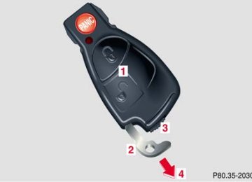
The electronic key has an integrated radio frequency and infrared remote control, plus removable mechanical key. The remote control (1) operates all locks on the vehicle. The mechanical key (2) works only in the driver’s door, trunk, and glove box lock.
When using the mechanical key (2) for lock operations, it can be removed by sliding it out of the remote control. To do so, move locking tab (3) to the right and slide the mechanical key (2) in direction of arrow (4). The remote control transmitter is located in the electronic key. The infrared receivers are located in the door handles.
Note: Remove the mechanical key from the electronic key when using valet parking service. To prevent access to trunk or storage compartments lock them separately and retain the mechanical key. See page 41 for separate locking of trunk and page 207 for locking of glove box.
Obtaining replacement keys Your vehicle is equipped with a theft deterrent locking system requiring a special key manufacturing process. For security reasons, replacement keys can only be obtained from your authorized Mercedes-Benz Center.
Central locking system
29
Instruments and controls
Operation
Driving
Instrument cluster display
Practical hints
Car care
Technical
data
Index
Instruments and controls
Operation
Driving
Instrument cluster display
Practical hints
Car care
Technical
data
Index
Central locking system
Start lock-out
30
Important! Removing the electronic key from the starter switch activates the start lock-out. The engine cannot be started. Inserting the electronic key in the starter switch deactivates the start lock-out.
Note: In case the engine cannot be started (vehicle’s battery is in order), the system is not operational. Contact an authorized Mercedes-Benz Center or call 1-800-FOR- MERCedes (in the USA), or 1-800-387-0100 (in Canada).
General notes on the central locking system If the electronic key is inserted in the starter switch, the vehicle cannot be locked or unlocked with the remote control. If the vehicle cannot be locked or unlocked: • Aim transmitter eye at a receiver of either door
handle. Check the batteries of the electronic key, see page 351, or synchronize the electronic key, see page 353.
• Use the mechanical key to unlock the vehicle. To
start engine, insert the electronic key in the starter switch. There could be a slight delay until the electronic key can be turned in the starter switch.
Important! When unlocking the driver’s door with the mechanical key, the exterior lamps will flash and the alarm will sound. To cancel the alarm, insert the electronic key in the starter switch or press button Œ or ‹ on the electronic key.
Central locking system
Radio frequency and infrared remote control The electronic key has an integrated radio frequency and infrared remote control. Due to the extended operational range of the remote control, it could be possible to unintentionally lock or unlock the vehicle by pressing the transmit button. If one of the transmit buttons is pressed, the battery check lamp lights up briefly – indicating that the batteries are in order. See page 351 for checking batteries. The vehicle doors, trunk and fuel filler flap can be centrally locked and unlocked via remote control. Opening and closing the windows and panorama sliding/pop-up roof can only be done with the infrared portion of the remote control. Aim transmitter eye at a receiver (6 or 7), press and hold transmit button Œ or ‹, see page 34. If the electronic key is inserted in starter switch, the vehicle cannot be locked or unlocked, and the trunk lid cannot be opened with the remote control.
P80.35-2033-26
1 Transmit button
‹ Locking Œ Unlocking
2 Lamp for battery check (see page 351 for changing
batteries if it does not light up briefly)
3 PANIC button 4 Transmitter eye 5 Locking tab for mechanical key
Central locking system
31
Instruments and controls
Operation
Driving
Instrument cluster display
Practical hints
Car care
Technical
data
Index
Instruments and controls
Operation
Driving
Instrument cluster display
Practical hints
Car care
Technical
data
Index
Central locking system
32
6 Infrared receiver in driver’s door handle
7 Infrared receiver in passenger door handle
P72.10-2313-26
P72.10-2315-26
Locking and unlocking with remote control
Unlocking: Press transmit button Œ. All turn signal lamps blink once to indicate that the vehicle is unlocked. The remote control can be programmed for two kinds of unlocking modes (see below): Selective unlocking mode – Press transmit button Œ once to unlock driver’s door and fuel filler flap. Press transmit button Œ twice to unlock all doors, fuel filler flap, and trunk. Global unlocking mode – Press transmit button Œ once to unlock all doors, fuel filler flap, and trunk.
Notes: The presently active unlocking mode (selective or global) can only be determined by unlocking the vehicle with the remote control (see below for changing mode).
If within 40 seconds of unlocking with the remote control, neither door or trunk is opened, the electronic key is not inserted in the starter switch, or the central locking switch is not activated, the vehicle will automatically lock.
Locking: Press transmit button ‹ once. All turn signal lamps blink three times to indicate that the vehicle is locked. If they do not blink three times, a door or trunk is not properly closed.
Note: If the vehicle cannot be locked or unlocked by pressing the transmit button, then it may be necessary to change the batteries in the electronic key (if ok, battery check lamp in electronic key will light briefly when pressing transmit button) or to synchronize the remote control, see pages 351 and 353.
Choosing global or selective mode on remote control Press and hold transmit buttons ‹ and Œ simultaneously for five seconds to reprogram the remote control. Battery check lamp will blink two times indicating the completed mode change.
Central locking system
33
Instruments and controls
Operation
Driving
Instrument cluster display
Practical hints
Car care
Technical
data
Index
Instruments and controls
Operation
Driving
Instrument cluster display
Practical hints
Car care
Technical
data
Index
Central locking system
34
Opening and closing windows and panorama sliding/pop-up roof from outside (summer opening/convenience feature) Aim transmitter eye of remote control at the door receiver.
Summer opening: The panorama sliding/pop-up roof and all side windows can be opened automatically. Continue to press transmit button Πafter unlocking the vehicle. The windows and panorama sliding/pop-up roof begin to open after a short time. To interrupt opening procedure, release transmit button.
Convenience feature: The panorama sliding/pop-up roof and the side windows can be closed. Continue to press transmit button ‹ after locking the vehicle. The windows and panorama sliding/pop-up roof begin to close after approximately 1 second.
To interrupt closing procedure, release transmit button. Ensure that all side windows and the panorama sliding/pop-up roof are properly closed before leaving the vehicle.
Warning! Never operate the windows or panorama sliding/ pop-up roof if there is the possibility of anyone being harmed by the opening or closing procedure. In case the procedure causes potential danger, the procedure can be immediately halted by releasing the remote control button. To reverse direction of movement press Œ for opening or ‹ for closing.
Note: If the windows and panorama sliding/pop-up roof cannot be operated automatically by pressing the transmit button of the remote control then it may be necessary to change the batteries in the electronic key (if ok, battery check lamp in electronic key will light briefly when transmitting), or to synchronize the remote control, see page 351 and 353.
Panic button
P80.35-2034-26
To activate press and hold button (1) for at least one second. An audible alarm and blinking exterior lamps will operate for approximately 3 minutes. To deactivate press button (1) again, or insert electronic key in starter switch.
Note: For operation in the USA only: This device complies with Part 15 of the FCC Rules. Operation is subject to the following two conditions: (1) This device may not cause harmful interference, and (2) this device must accept any interference received, including interference that may cause undesired operation. Any unauthorized modification to this device could void to the user’s authority to operate the equipment.
Mechanical keys The mechanical keys work only in driver’s door, trunk, and glove box locks.
Notes: The mechanical key does not operate the central locking system or antitheft alarm system. The fuel filler flap cannot be locked or unlocked with the mechanical key. If the fuel filler flap cannot be opened, see page 354.
Central locking system
35
Instruments and controls
Operation
Driving
Instrument cluster display
Practical hints
Car care
Technical
data
Index
Instruments and controls
Operation
Driving
Instrument cluster display
Practical hints
Car care
Technical
data
Index
Central locking system
Doors
36
P72.10-2314-26
P72.10-2316-26
1 Opening – pull handle 2 Unlocking driver’s door 3 Locking driver’s door
Important! The mechanical key does not operate the central locking system or antitheft alarm system.
4 Individual door from inside:
Push lock button down to lock.
5 Individual door from inside:
Pull handle to unlock.
When you lock the driver’s door with the mechanical key, the door lock button should move down. Each individual door must be locked with the respective door lock button – the driver’s door can only be locked when it is closed.
To unlock, pull inside door handles or turn mechanical key in driver’s door lock to position 2. When unlocking the driver’s door with the mechanical key, the exterior lamps will flash and the alarm will sound. To cancel the alarm, insert the electronic key in the starter switch or press button Œ or ‹ on the electronic key.
If the vehicle has previously been locked from the outside, opening a door from the inside will trigger the alarm. When opening a door while the central locking system is in the: • selective unlocking mode, only that individual door
is unlocked. The remaining doors, the trunk and fuel filler flap remain locked.
• global unlocking mode, all doors, the trunk and fuel
filler flap are unlocked.
Notes: In case of a malfunction in the central locking system the doors can be locked and unlocked individually. To lock, push down lock buttons or turn mechanical key in driver’s door lock to position 3. In addition lock the trunk.
Central locking system
37
Instruments and controls
Operation
Driving
Instrument cluster display
Practical hints
Car care
Technical
data
Index
Instruments and controls
Operation
Driving
Instrument cluster display
Practical hints
Car care
Technical
data
Index
Central locking system
38
Central locking switch
The central locking switch is located in the center console. The doors and trunk can only be locked with the central locking switch, if both doors are closed. If the vehicle was previously locked with the central locking switch, while in the selective remote control mode, only the door opened from the inside is unlocked. If the vehicle was previously locked with the central locking switch, while in the global remote control mode, the complete vehicle is unlocked when a door is opened from the inside.
1 Locking 2 Unlocking
P54.25-2499-26
Notes: If the vehicle was previously locked with the remote control, the doors and trunk cannot be unlocked with the central locking switch. The fuel filler flap cannot be locked or unlocked with the central locking switch. If the vehicle has previously been locked from the outside, opening a door from the inside will trigger the alarm. To cancel the alarm, insert the electronic key in the starter switch or press button Œ or ‹ on the electronic key.
Warning! When leaving the vehicle always remove the electronic key from the starter switch, and lock your vehicle. Do not leave children unattended in the vehicle, or with access to an unlocked vehicle. Unsupervised use of vehicle equipment may cause serious personal injury.
Central locking system
39
Instruments and controls
Operation
Driving
Instrument cluster display
Practical hints
Car care
Technical
data
Index
Instruments and controls
Operation
Driving
Instrument cluster display
Practical hints
Car care
Technical
data
Index
Central locking system
40
Automatic central locking With the automatic central locking system activated, the doors and trunk are locked at vehicle speeds of approximately 9 mph (15 km/h) or more. The fuel filler flap remains unlocked. The automatic central locking function can be switched on or off in the individual setting menu “VEHICLE” – “AUTOMATIC DOOR LOCK”, see page 121.
Notes: If doors are unlocked with the central locking switch after activating the automatic central locking, and neither door is opened, then the doors remain unlocked even at vehicle speeds of approximately 9 mph (15 km/h) or more. If a door is opened from the inside at speeds of approximately 9 mph (15 km/h) or less with the automatic central locking activated, the door will again be automatically locked at speeds of approximately 9 mph (15 km/h) or more.
If a door is opened from the inside, the complete vehicle is unlocked, if the vehicle was previously centrally unlocked using the remote control.
Important! When towing the vehicle, or with the vehicle on a dynamometer test stand, please, note the following: With the automatic central locking activated and the electronic key in starter switch position 2, the vehicle doors will lock if the left front wheel as well as the right rear wheel spin at vehicle speeds of approximately 9 mph (15 km/h) or more.
Emergency unlocking in case of accident The doors unlock automatically a short time after an accident in which an airbag or emergency tensioning retractor deploys (this is intended to aid rescue and exit).
Trunk The lock is located next to the recessed handle.
Notes: In case of a malfunction in the central locking system the trunk can be unlocked individually. The mechanical key does not operate the central locking system or antitheft alarm system. When unlocking the trunk with the mechanical key, the exterior lamps will flash and the alarm will sound. To cancel the alarm, insert the electronic key in the starter switch or press button Œ or ‹ on the electronic key. If the fuel filler flap cannot be opened, see page 354.
P88.50-2273-26
0 Neutral position 1 Unlocking – turn mechanical key to position 1, hold
and pull handle to open
Important! Do not place mechanical key inside trunk, since trunk is locked again when closing the lid if the vehicle has been previously centrally locked.
Central locking system
41
Instruments and controls
Operation
Driving
Instrument cluster display
Practical hints
Car care
Technical
data
Index
Instruments and controls
Operation
Driving
Instrument cluster display
Practical hints
Car care
Technical
data
Index
Central locking system
42
Pull handle (arrow) to open the trunk lid. The trunk lid can only be opened manually if the vehicle was previously centrally unlocked.
Lower trunk lid using handle (1) and close it with hands placed flat on trunk lid. Please remember to keep your fingers out of the space between the lid and the vehicle.
Trunk lamp The trunk lamp will switch off after approximately 10 minutes if the trunk lid is left open.
Trunk lid emergency release
P80.20-2301-26
The emergency release button (1) is located in the trunk lid. Briefly press emergency release button (1). The trunk unlocks and the trunk lid opens.
Important! The emergency release button (1) does not open the trunk lid, if the vehicle battery is discharged or disconnected. Illumination of the emergency release button (1): The button will blink for 30 minutes after opening the trunk. The button will blink for 60 minutes after closing the trunk.
Note: When pressing the emergency release button (1) and the vehicle was centrally locked, the exterior lamps will flash and the alarm will sound. To cancel the alarm, insert the electronic key in the starter switch or press button Œ or ‹ on the electronic key.
Central locking system
43
Instruments and controls
Operation
Driving
Instrument cluster display
Practical hints
Car care
Technical
data
Index
Instruments and controls
Operation
Driving
Instrument cluster display
Practical hints
Car care
Technical
data
Index
Antitheft alarm system
44
Antitheft alarm system (optional for Canada )
The antitheft alarm is automatically armed or disarmed with the remote control by locking or unlocking the vehicle. The antitheft alarm is armed within approximately 10 seconds after locking the vehicle. A blinking lamp (1) indicates that the alarm is armed.
1 Indicator lamp in switch located in center console
P54.25-2500-26
Notes: When you unlock the driver’s door with the mechanical key, the exterior lamps will flash and the alarm will sound. To cancel the alarm, insert the electronic key in the starter switch or press button Œ or ‹ on the electronic key.
Operation: Once the alarm system has been armed, the exterior vehicle lamps will flash and an alarm will sound when someone: • opens a door, • opens the trunk, • opens the hood, • attempts to raise the vehicle.
The alarm will last approximately 3 minutes in form of flashing exterior lamps. At the same time an alarm will sound for 30 seconds. The alarm will stay on even if the activating element (a door, for example) is immediately closed. If the alarm stays on for more than 20 seconds, an emergency call is initiated automatically. See Tele Aid on page 228.
Antitheft alarm system
45
Instruments and controls
Operation
Driving
Instrument cluster display
Practical hints
Car care
Technical
data
Index
Instruments and controls
Tow-away alarm
Operation
Driving
Instrument cluster display
Practical hints
Car care
Technical
data
Index
Tow-away alarm (optional for Canada)
The switch is located in the center console.
1 Press to switch off tow-away alarm 2 Indicator lamp Once the alarm system has been armed, the exterior vehicle lamps will flash and an alarm will sound when someone attempts to raise the vehicle.
46
The alarm will last approximately 3 minutes in form of flashing exterior lamps. At the same time an alarm will sound for 30 seconds. The alarm will stay on even if the vehicle is immediately lowered. To cancel the alarm, insert the electronic key in the starter switch or press button Œ or ‹ on the electronic key. If the alarm stays on for more than 20 seconds, an emergency call is initiated automatically. See Tele Aid on page 228. To prevent triggering the tow-away alarm feature, switch off the tow-away alarm before towing the vehicle, or when parking on a surface subject to movement, such as a ferry or auto train. To do so, turn electronic key in starter switch to position 0 or 1, or remove electronic key from starter switch. Press tow-away alarm switch (1). The indicator lamp (2) illuminates briefly. Exit vehicle, and lock vehicle with the electronic key. The tow-away alarm remains switched off until the vehicle is locked again with the electronic key, at which time it is automatically reactivated.
Easy-entry/exit feature (only vehicles with memory function) With the easy-entry/exit feature activated the steering wheel tilts upwards and the driver’s seat moves rearwards, when removing the electronic key from the starter switch or when opening the driver’s door and the electronic key in starter switch position 0 or 1. This allows easier entry into and exit from the vehicle when the driver’s door is opened. The easy-entry/exit feature can be switched on or off in the individual setting menu “CONVENIENCE” – “EASY-ENTRY FEATURE ACTIVATE”, see page 134. When the electronic key is inserted in the starter switch and the driver’s door is closed, the steering wheel and the driver’s seat return to the last position set for it.
Warning! You must ensure that no one can become trapped or injured by the moving steering wheel when the easy-entry/exit feature is activated and the driver’s door is being opened or the electronic key removed from the starter switch. Do not leave children unattended in the vehicle, or with access to an unlocked vehicle. Unsupervised use of vehicle equipment may cause serious personal injury.
Easy-entry/exit feature
47
Instruments and controls
Operation
Driving
Instrument cluster display
Practical hints
Car care
Technical
data
Index
Instruments and controls
Seats
Operation
Driving
Instrument cluster display
Practical hints
Car care
Technical
data
Index
Front seat adjustment
Warning! Do not adjust the driver’s seat while driving. Adjusting the seat while driving could cause the driver to lose control of the vehicle. Never ride in a moving vehicle with the seat back reclined. Sitting in an excessively reclined position can be dangerous. You could slide under the seat belt in a collision. If you slide under it, the belt would apply force at the abdomen or neck. That could cause serious or fatal injuries. The seat back and seat belts provide the best restraint when the wearer is in an upright position and belts are properly positioned on the body. Never place hands under seat or near any moving parts while a seat is being adjusted.
48
When leaving the vehicle always remove the electronic key from the starter switch, and lock your vehicle. The power seats can also be operated with the driver’s or front passenger door open. Do not leave children unattended in the vehicle, or with access to an unlocked vehicle. Unsupervised use of vehicle equipment may cause serious personal injury.
To operate the front power seat adjustment switches, turn the electronic key in starter switch to position 1 or 2 (with respective door open, the power seats can also be operated with the electronic key removed or in starter switch position 0).
Power seat (optional)
2 Seat adjustment, fore/aft
Press the switch (fore/aft direction) until a comfortable seating position is reached that still allows you to reach the accelerator/brake pedal safely. The position should be as far rearward as possible, consistent with ability to properly operate controls.
3 Seat cushion tilt
Press the switch in the direction of the arrow until your legs are lightly supported.
The switches are located in each door. We recommend to adjust the power seat in the following order:
1 Seat, up/down
Press the switch (up/down direction) until comfortable seating position with still sufficient headroom is reached.
4 Backrest tilt
Press the switch in the direction of the arrow until your arms are slightly angled when holding the steering wheel. 5 Head restraint
The height of the head restraint is adjusted automatically with the seat so that the back of the head is supported approximately at ear level. Adjust the head restraint using the switch to support the back of your head approximately at ear level.
For exterior rear view mirrors, see page 90; inside rear view mirror, see page 89; steering wheel adjustment, see page 88.
49
Seats
Instruments and controls
Operation
Driving
Instrument cluster display
Practical hints
Car care
Technical
data
Index
Instruments and controls
Seats
Operation
Driving
Instrument cluster display
Practical hints
Car care
Technical
data
Index
50
Storing seat positions: (only vehicles with memory function) The steering wheel and exterior rear view mirror position are stored together with the seat position. See page 93 for notes on the memory function. For recalling a stored seat/head restraint/steering wheel/ and exterior rear view mirror position see page 94.
Adjust the head restraint angle by hand. Push or pull the head restraint in direction of arrow.
Manual seat (standard)
We recommend to adjust the seat in the following order:
1 Fore/aft adjustment
Lift handle (1), slide seat to desired position and allow handle to reengage. Check for proper engagement before driving.
2 Seat cushion tilt
Turn handwheel (2) forward or backward.
3 Seat height adjustment
Pull handle (3) up to raise seat cushion. Push handle (3) down to lower seat cushion.
4 Backrest tilt
Turn handwheel (4) forward or backwards until your arms are slightly angled when holding the steering wheel.
Seats
Instruments and controls
Operation
Driving
Instrument cluster display
Practical hints
Car care
Technical
data
Index
51
Instruments and controls
Seats
Operation
Driving
Instrument cluster display
Practical hints
Car care
Technical
data
Index
52
Head restraint inclination
Push or pull the head restraint in direction of arrow.
5 Head restraint height
Raising: Pull up on head restraint.
Lowering: Push button (5) and push down on head restraint. Adjust head restraint to support the back of the head approximately at ear level. The head restraint inclination can also be adjusted manually.
Important! Prior to operating the vehicle, the driver should adjust the seat height for proper vision as well as fore/aft placement and backrest angle to insure adequate control, reach, operation, and comfort. The head restraint should also be adjusted for proper height. See also airbag section on page 72 for proper seat positioning. In addition, also adjust the steering wheel to ensure adequate control, reach, operation, and comfort. Both the inside and outside rear view mirrors should be adjusted for adequate rearward vision. Fasten seat belts. Infants and small children should be seated in a properly secured restraint system that complies with U.S. Federal Motor Vehicle Safety Standard 213 and Canadian Motor Vehicle Safety Standard 213. All seat, head restraint, steering wheel, and rear view mirror adjustments as well as fastening of seat belts should be done before the vehicle is put into motion.
Warning! Children 12 years old and under must never ride in the front seat, except in a Mercedes-Benz authorized BabySmartTM compatible child seat, which operates with the BabySmartTM system installed in the vehicle to deactivate the passenger side front airbag when it is properly installed. Otherwise they will be struck by the airbag when it inflates in a crash. If this happens, serious or fatal injury can result. According to accident statistics, children are safer when properly restrained in the rear seating positions than in the front seating positions. Infants and small children must ride in back seats and be seated in an appropriate infant or child restraint system, which is properly secured with the vehicle’s seat belt, fully in accordance with the child seat manufacturer’s instructions. A child’s risk of serious or fatal injuries is significantly increased if the child restraints are not properly secured in the vehicle and the child is not properly secured in the child restraint.
Seats
Instruments and controls
Operation
Driving
Instrument cluster display
Practical hints
Car care
Technical
data
Index
53
Instruments and controls
Seats
Operation
Driving
Instrument cluster display
Practical hints
Car care
Technical
data
Index
Removal and installation of front seat head restraints Power seat
Caution! Do not remove head restraints except when mounting seat covers. Whenever restraints have been removed be sure to reinstall them before driving.
54
Note: Tilt the backrest rearward for easier removal and installation of the head restraints. To remove: Press switch (1) upwards and hold until the head restraint is fully extended. Pull head restraint out. To install: Press switch (1) upwards and hold for about 5 seconds. Press the head restraint down until it engages. Adjust head restraint to the desired position.
Warning! For your protection, drive only with properly positioned head restraints. Adjust head restraint to support the back of the head approximately at ear level. Do not drive the vehicle without the seat head restraints. Head restraints are intended to help reduce injuries during an accident.
Manual seat
Warning! For your protection, drive only with properly positioned head restraints. Adjust head restraint to support the back of the head approximately at ear level. Do not drive the vehicle without the seat head restraints. Head restraints are intended to help reduce injuries during an accident.
To remove: Pull head restraint to its highest position. Push button (1) and pull out head restraint completely. To install: Insert head restraint and push it down to the stop. Push button (1) and adjust head restraint to the desired position.
Seats
Instruments and controls
Operation
Driving
Instrument cluster display
Practical hints
Car care
Technical
data
Index
55
Instruments and controls
Seats
Operation
Driving
Instrument cluster display
Practical hints
Car care
Technical
data
Index
56
Folding back: Fold backrest back until it locks securely in place. Adjust head restraint to support the back of the head approximately at ear level, see page 52.
Note: Vehicles with power seat: The seat and head restraint return to their previous positions.
Front seat backrest - locking and unlocking
1 Release lever Folding forward: Lift release lever (1) and fold backrest forward, when necessary, lower head restraint by pushing it.
Note: Vehicles with power seat: The seat will automatically slide forward and the head restraints will move down.
Warning! When leaving the vehicle always remove the electronic key from the steering lock, and lock your vehicle. The power seats can also be operated with the driver’s or passenger door open. Do not leave children unattended in the vehicle or with access to an unlocked vehicle. Unsupervised use of vehicle equipment may cause serious personal injury. Never place hands under seat or near any moving parts during a seat adjustment procedure.
Warning! When raising backrest, observe that backrest is not pushed against an occupant or object. Vehicles with manual seat: After folding backrest up, adjust head restraint to support the back of the head approximately at ear level.
Seats
Instruments and controls
Operation
Driving
Instrument cluster display
Practical hints
Car care
Technical
data
Index
57
Instruments and controls
Seats
Operation
Driving
Instrument cluster display
Practical hints
Car care
Technical
data
Index
58
Heated seats (optional)
Press switch to turn on seat heater:
1 Normal seat heating mode. One indicator lamp in
the switch lights up.
2 Rapid seat heating mode. Both indicator lamps in the switch light up. After approximately 5 minutes in the rapid seat heating mode, the seat heater automatically switches to normal operation and only one indicator lamp will stay on.
Turning off seat heater: If one indicator lamp is on, press upper half of switch. If both indicator lamps are on, press lower half of switch. If left on, the seat heater automatically turns off after approximately 30 minutes of operation.
P54.25-2501-26
The front seat heaters can be switched on with the electronic key in starter switch position 1 or 2. The switch is located in the center console.
Note: When in operation, the seat heater consumes a large amount of electrical power. It is not advisable to use the seat heater longer than necessary. The seat heaters may automatically switch off if too many power consumers are switched on at the same time, or if the battery charge is low. When this occurs, the indicator lamp in the switch will blink (both indicator lamps blink during rapid seat heating mode). The seat heaters will switch on again automatically as soon as sufficient voltage is available. If the blinking of the indicator lamps is distracting to you, the seat heaters can be switched off.
Seats
Instruments and controls
Operation
Driving
Instrument cluster display
Practical hints
Car care
Technical
data
Index
59
Instruments and controls
Seats
Operation
Driving
Instrument cluster display
Practical hints
Car care
Technical
data
Index
60
Rear seat head restraints
Place head restraints upright
P91.16-2104-26
P91.16-2105-26
Folding head restraints back in the rear passenger compartment: Push lock button (1). The head restraints will fold backward.
Placing head restraints upright: Pull the head restraint forward until it locks into position.
Angle of head restraints: Two different head restraint angle positions are available.
Head restraint height
Adjust head restraint to support the back of the head approximately at ear level. The head restraint inclination can also be adjusted manually.
Important! For safety reasons, always drive with the rear head restraints in upright position when the rear seats are occupied. Keep the area around head restraints clear of articles (e.g. clothing) to not obstruct the folding operation of the head restraints.
Raising: Pull up on head restraint. If the head restraint is fully lowered, press button (2) to pull up.
Lowering: Push button (2) and push down on head restraint.
Seats
Instruments and controls
Operation
Driving
Instrument cluster display
Practical hints
Car care
Technical
data
Index
61
Instruments and controls
Operation
Driving
Instrument cluster display
Practical hints
Car care
Technical
data
Index
Restraint systems
62
Seat belts and integrated restraint system Your vehicle is equipped with seat belts for all seats, emergency tensioning retractors for all seat belts, dual front airbags, door mounted side impact airbags, and head protective window curtain airbags. Their protective functions are designed to complement one another.
Seat belts
Important! Laws in most states and all Canadian provinces require seat belt use. All states and provinces require use of child restraints that comply with U.S. Federal Motor Vehicle Safety Standard 213 and Canadian Motor Vehicle Safety Standard 213. All child restraints systems are designed to be secured in vehicle seats by lap belts or the lap belt portion of a lap-shoulder belt. For your safety and that of your passengers we strongly recommend their use.
Warning! Children 12 years old and under must never ride in the front seat, except in a Mercedes-Benz authorized BabySmartTM compatible child seat, which operates with the BabySmartTM system installed in the vehicle to deactivate the passenger side front airbag when it is properly installed. Otherwise they will be struck by the airbag when it inflates in a crash. If this happens, serious or fatal injury will result. According to accident statistics, children are safer when properly restrained in the rear seating positions than in the front seating positions. Infants and small children must ride in back seats and be seated in an appropriate infant or child restraint system, which is properly secured with the vehicle’s seat belt, fully in accordance with the child seat manufacturer’s instructions. A child’s risk of serious or fatal injuries is significantly increased if the child restraints are not properly secured in the vehicle and the child is not properly secured in the child restraint.
Warning! Never ride in a moving vehicle with the backrest reclined. Sitting in an excessively reclined position can be dangerous. You could slide under the seat belt in a collision. If you slide under it, the belt would apply force at the abdomen or neck. That could cause serious or even fatal injuries. The backrest and seat belt provide the best restraint when the wearer is in an upright position and the belt is properly positioned on the body.
Seat belt nonusage warning system With the electronic key in starter switch position 2, a warning sounds for a short time if the driver’s seat belt is not fastened. Automatic comfort-fit seat belt: An automatic comfort-fit feature for driver and front passenger seat belt is activated when the electronic key in the starter switch is turned to position 1 or 2. The retraction force of the inertia reel is reduced, increasing the level of seat belt comfort.
Note: For cleaning and care of the seat belts see page 365.
Restraint systems
63
Instruments and controls
Operation
Driving
Instrument cluster display