- Download PDF Manual
-
force to both rear wheels and reduces wheel spin caused by the loss of traction at one driving wheel. If traction differs between the two rear wheels, the differential automatically proportions the usable torque by providing more torque to the wheel that has traction. Trac-Lok™ is especially helpful during slippery driving conditions. With both rear wheels on a slippery surface, a
slight application of the accelerator will supply maxi- mum traction. When starting with only one rear wheel on an excessively slippery surface, slight application of the parking brake may be necessary to gain maximum trac- tion.
WARNING!
On vehicles equipped with a limited-slip differen- tial, never run the engine with one rear wheel off the ground. The vehicle may drive through the rear wheel remaining on the ground and cause you to lose control of your vehicle.
STARTING AND OPERATING 199
AXLE LOCK (TRU–LOK™) — IF EQUIPPED The Axle Lock switch is located on the lower center of the instrument panel.
Axle Lock Switch
This feature will only activate when the following con- ditions are met: • Key in ignition, vehicle in 4L (Low) range.
200 STARTING AND OPERATING
• Vehicle speed should be 10 mph (16 km/h) or less. To activate the system, press the switch once to lock the rear axle only (the REAR LOCK indicator light will illuminate), press the switch again to lock the front axle (the FRONT LOCK indicator light will illuminate). Once the rear axle is locked, pressing the switch again will lock or unlock the front axle. NOTE: The indicator lights will flash until the axles are fully locked or unlocked. A chime will sound three times and the indicator lights will continue to flash at a different rate if the key is removed while the axles are still in the locked position. To unlock the axles, pull up on the switch. Axle lock will disengage if vehicle is taken out of 4L (Low) range.
PARKING BRAKE To set the parking brake, pull the lever up as firmly as possible. When the parking brake is applied with the ignition ON, the BRAKE warning light in the instrument cluster will light. NOTE: The BRAKE warning light indicates only that the parking brake is applied. It does not indicate the degree of brake application. If the parking brake is applied and the vehicle is NOTE: in motion, the BRAKE warning light will flash and a chime will sound. To release the parking brake, pull up slightly, press center button, then lower lever completely.
STARTING AND OPERATING 201
If the parking brake is not completely released, the BRAKE warning light will remain on. NOTE: Your vehicle has automatically adjusting rear brakes and we do not recommend any adjustment other than the maintenance performed by your authorized dealer. Before leaving the vehicle parked on a hill, you must make sure the parking brake is fully applied and place the gear selector in the P (Park) position (automatic transmission) or first gear (manual transmission). Make certain the transfer case is in gear. Failure to do so may cause the vehicle to roll and cause damage or injury.
Parking Brake Release
202 STARTING AND OPERATING
WARNING!
• Always fully apply the parking brake when leav- ing your vehicle, or vehicle may roll and cause damage or injury. Also be certain to leave a automatic transmission in P (Park), or a manual transmission in 1st gear. Make certain the transfer case is in gear. Failure to do so may cause the vehicle to roll and cause damage or injury. • If the parking brake is released, and the BRAKE warning light glows while the ignition switch is ON or the engine is running, there may be a brake system problem. Brake pedal travel, effort and stopping distances may increase, and you should obtain corrective service immediately.
When parking on a hill, it is important to set the parking brake before placing the gear selector in P (Park), other- wise the load on the transmission locking mechanism may make it difficult to move the selector out of P (Park). The parking brake should always be applied when the driver is not in the vehicle.
WARNING!
• Leaving children unattended in a vehicle is dan- gerous for a number of reasons. A child or others could be injured. Children should be warned not to touch the parking brake or the gear selector lever. Don’t leave the keys in the ignition. A child could operate controls or move the vehicle.
STARTING AND OPERATING 203
If either of two hydraulic systems lose normal capability, the remaining system will still function with some loss of overall braking effectiveness. This will be evident by increased pedal travel during application and greater pedal force required to slow or stop.
ABOUT YOUR BRAKES Your vehicle is equipped with power assisted brakes as standard equipment. In the event power assist is lost for any reason (for example, repeated brake applications with the engine off), the brakes will still function. The effort required to brake the vehicle will be much greater than that required with the power system operating.
WARNING!
Riding the brakes can lead to brake failure and possibly an accident. Driving with your foot resting or riding on the brake pedal can result in abnormally high brake temperatures, excessive lining wear, and possible brake damage. You wouldn’t have your full braking capacity in an emergency.
204 STARTING AND OPERATING
WARNING!
WARNING!
To use your brakes and decelerate more safely, follow these tips:
overheat the brakes and result in unpredictable braking action, longer stopping distances, or brake damage.
• Do not “ride” the brakes by resting your foot on the pedal. This could • When descending mountains or hills, repeated braking can cause • Do not downshift on icy or slippery roads, because engine braking • Engines may idle at higher speeds during warm-up, which could
brake fade with loss of braking control. Avoid repeated heavy braking by downshifting the transmission whenever possible.
may cause skidding and loss of control.
cause rear wheels to spin and result in loss of vehicle control. Be especially careful while driving on slippery roads, in close-quarter maneuvering, parking or stopping. Remember, always engage 4-wheel drive when driving on slippery roads.
• Do not drive too fast for road conditions, especially when roads are wet
or slushy. A wedge of water can build up between the tire tread and the road. This hydroplaning action can cause loss of traction, braking ability, and control. Under such conditions, engage 4-wheel drive.
• After going through deep water or a car wash, brakes may become
wet, resulting in poor performance and unpredictable braking action. Dry the brakes by gentle, intermittent pedal action while driving at very slow speeds.
heavier objects as low and as far forward as possible.
The weight and position of cargo and passengers can change the vehicle center of gravity and vehicle handling. To avoid loss of control resulting in personal injury, follow these guidelines: • Always place cargo evenly on the cargo floor, and locate • Place as much cargo as possible in front of the rear axle. Too much weight or improperly placed weight over or behind the rear axle can cause the rear of the vehicle to sway. • Do not pile luggage or cargo higher than the top of the seatback. This could impair visibility or become a danger- ous projectile in a sudden stop or collision. • The rear cargo space is intended for load carrying purposes only, not for passengers, who should sit in seats and use seat belts. • On hardtop models, do not drive with the lift glass up. On fabric top models, do not drive with the rear window curtain up unless the side curtains are also open. This will prevent dangerous exhaust fumes from entering the vehicle.
WARNING!
To help avoid personal injury, follow these tips: • Never reach through the steering wheel to operate steering column controls. Injury to your hands or loss of vehicle control may result. • If the engine stalls or power assist fails due to a malfunction, vehicle steering and braking will require greater effort.
ANTI-LOCK BRAKE SYSTEM — IF EQUIPPED The Anti-Lock Brake System is designed to aid the driver in maintaining vehicle control under adverse braking conditions. The system operates with a separate com- puter to modulate hydraulic pressure to prevent wheel lock-up and help avoid skidding on slippery surfaces.
STARTING AND OPERATING 205
All vehicle wheels and tires must be the same size and type and tires must be properly inflated to produce accurate signals for the computer.
WARNING!
Significant over or under-inflation of tires, or mixing sizes of tires or wheels on the vehicle can lead to loss of braking effectiveness.
The Anti-Lock Brake System conducts a low speed self- test at about 12 mph (20 km/h). If for any reason, your foot is on the brake when the vehicle reaches 12 mph (20
km/h), this check will be delayed until 25 mph (40
km/h).206 STARTING AND OPERATING
The Anti-Lock Brake System pump motor runs during the self-test and during an ABS stop to provide the regulated hydraulic pressure. The motor pump makes a low humming noise during operation, this is normal. During off-road use, loss of traction can temporarily defeat the system and cause the warning light to illumi- nate. Turn the ignition OFF and ON again to restore Anti-Lock Brake System function.
WARNING!
Pumping of the Anti-Lock Brakes will diminish their effectiveness and may lead to an accident. Pumping makes the stopping distance longer. Just press firmly on your brake pedal when you need to slow down or stop.
WARNING!
• Anti-lock system (ABS) cannot prevent the natu- ral laws of physics from acting on the vehicle, nor can it increase braking or steering efficiency be- yond that afforded by the condition of the vehicle brakes and tires or the traction afforded.
• The ABS cannot prevent accidents,
including those resulting from excessive speed in turns, following another vehicle too closely, or hydro- planing. Only a safe, attentive, and skillful driver can prevent accidents. • The capabilities of an ABS equipped vehicle must never be exploited in a reckless or dangerous manner which could jeopardize the user’s safety or the safety of others.
CAUTION!
The Anti-Lock Brake System is subject to possible detrimental effects of electronic interference caused by improperly installed aftermarket radios or tele- phones.
NOTE: During severe braking conditions, a pulsing sensation may occur and a clicking noise will be heard. This is normal, the Anti-Lock Brake System is functioning.
indicating that
POWER STEERING The standard power steering system will give you good vehicle response and increased ease of maneuverability in tight spaces. The system will provide mechanical steering capability if power assist is lost.
STARTING AND OPERATING 207
If for some reason, the power assist is interrupted, it will still be possible to steer your vehicle. Under these condi- tions you will observe a substantial increase in steering effort, especially at very low vehicle speeds and during parking maneuvers. Increased noise levels at the end of the steering NOTE: wheel travel are considered normal and does not indicate that there is a problem with the power steering system. Upon initial start-up in cold weather, the power steering pump may make noise for a short period of time. This is due to the cold, thick fluid in the steering system. This noise should be considered normal, and does not in any way damage the steering system.
208 STARTING AND OPERATING
WARNING!
Continued operation with reduced power steering assist could pose a safety risk to yourself and others. Service should be obtained as soon as possible.
CAUTION!
Prolong operation of the steering system at the end of the steering wheel travel will increase the steering fluid temperature and should be avoided when possible. Damage to the power steering pump may occur.
ON-ROAD DRIVING TIPS Utility vehicles have higher ground clearance and a narrower track to make them capable of performing in a wide variety of off-road applications. Specific design characteristics give them a higher center of gravity than ordinary cars. An advantage of the higher ground clearance is a better view of the road, allowing you to anticipate problems. They are not designed for cornering at the same speeds as conventional 2-wheel drive vehicles any more than low- slung sports cars are designed to perform satisfactorily in off-road conditions. If at all possible, avoid sharp turns or abrupt maneuvers. As with other vehicles of this type, failure to operate this vehicle correctly may result in loss of control or vehicle rollover.
OFF-ROAD DRIVING TIPS
When To Use 4L (Low) Range When off-road driving, shift to 4L (Low) for additional traction and control on slippery or difficult terrain, ascending or descending steep hills, and to increase low speed pulling power. This range should be limited to extreme situations such as deep snow, mud, steep in- clines, or sand where additional low speed pulling power is needed. Vehicle speeds in excess of 25 mph (40 km/h) should be avoided when in 4L (Low) range. Driving Through Water Although your vehicle is capable of driving through water, there are a number of precautions that must be considered before entering the water:
STARTING AND OPERATING 209
CAUTION!
When driving through water, do not exceed 5 mph (8
km/h). Always check water depth before entering as a precaution, and check all fluids afterward. Driving through water may cause damage that may not be covered by the new vehicle limited warranty.Driving through water more than a few inches deep will require extra caution to ensure safety and prevent dam- age to your vehicle. If you must drive through water, try to determine the depth and the bottom condition (and location of any obstacles) prior to entering. Proceed with caution and maintain a steady controlled speed less than 5 mph (8 km/h) in deep water to minimize wave effects. Flowing Water If the water is swift flowing and rising (as in storm run-off) avoid crossing until the water level recedes
210 STARTING AND OPERATING
and/or the flow rate is reduced. If you must cross flowing water avoid depths in excess of 9 inches. The flowing water can erode the streambed causing your vehicle to sink into deeper water. Determine exit point(s) that are downstream of your entry point to allow for drifting. Standing Water Avoid driving in standing water deeper than 20 inches, and reduce speed appropriately to minimize wave ef- fects. Maximum speed in 20 inches of water is less than 5
mph (8 km/h). Maintenance After driving through deep water, inspect your vehicle fluids and lubricants (engine oil, transmission oil, axle, transfer case) to assure the fluids have not been contami- nated. Contaminated fluid (milky, foamy in appearance) should be flushed/changed as soon as possible to pre- vent component damage.Driving In Snow, Mud and Sand In heavy snow, when pulling a load, or for additional control at slower speeds, shift the transmission to a low gear and shift the transfer case to 4L (Low) if necessary. Refer to “Four-Wheel Drive Operation” in this section. Do not shift to a lower gear than necessary to maintain headway. Over-revving the engine can spin the wheels and traction will be lost. Avoid abrupt downshifts on icy or slippery roads, be- cause engine braking may cause skidding and loss of control. Hill Climbing
NOTE: Before attempting to climb a hill, determine the conditions at the crest and/or on the other side. Before climbing a steep hill, shift the transmission to a lower gear and shift the transfer case to 4L (Low). Use first gear and 4L (Low) for very steep hills.
If you stall or begin to lose headway while climbing a steep hill, allow your vehicle to come to a stop and immediately apply the brakes. Restart the engine and shift to R (Reverse). Back slowly down the hill allowing the compression braking of the engine to help regulate your speed. If the brakes are required to control vehicle speed, apply them lightly and avoid locking or skidding the tires.
WARNING!
If the engine stalls or you lose headway or cannot make it to the top of a steep hill or grade, never attempt to turn around. To do so may result in tipping and rolling the vehicle. Always back care- fully straight down a hill in R (Reverse) gear. Never back down a hill in N (Neutral) using only the brake.
STARTING AND OPERATING 211
Remember, never drive diagonally across a hill-always drive straight up or down.
If the wheels start to slip as you approach the crest of a hill, ease off the accelerator and maintain headway by turning the front wheels slowly left and right. This may provide a fresh “bite” into the surface and will usually provide traction to complete the climb. Traction Downhill Shift the transmission into a low gear and the transfer case to 4L (Low) range. Let the vehicle go slowly down the hill with all four wheels turning against engine compression drag. This will permit you to control the vehicle speed and direction. When descending mountains or hills, repeated braking can cause brake fade with loss of braking control. Avoid repeated heavy braking by downshifting the transmis- sion whenever possible.
212 STARTING AND OPERATING
After Driving Off-Road Off-road operation puts more stress on your vehicle than does most on-road driving. After going off-road it is always a good idea to check for damage. That way you can get any problems taken care of right away and have your vehicle ready when you need it. • Completely inspect the underbody of your vehicle. Check tires, body structure, steering, suspension, and exhaust system for damage. • Check threaded fasteners for looseness, particularly on the chassis, drivetrain components, steering, and sus- pension. Retighten them, if required, and torque to the values specified in the Service Manual. • Check for accumulations of plants or brush. These things could be a fire hazard. They might hide damage to fuel lines, brake hoses, axle pinion seals, and propeller shafts.
• After extended operation in mud, sand, water, or similar dirty conditions, have brake rotors, wheels, brake linings, and axle yokes inspected and cleaned as soon as possible.
WARNING!
Abrasive material in any part of the brakes may cause excessive wear or unpredictable braking. You might not have full braking power when you need it to prevent an accident. If you have been operating your vehicle in dirty conditions, get your brakes checked and cleaned as necessary. • If you experience unusual vibration after driving in mud, slush or similar conditions, check the wheels for impacted material. Impacted material can cause a wheel imbalance and freeing the wheels of it will correct the situation.
TIRE SAFETY INFORMATION
Tire Markings
NOTE: • P(Passenger)-Metric tire sizing is based on U.S. design standards. P-Metric tires have the letter “P” molded into the sidewall preceding the size designation. Ex- ample: P215/65R15 95H.
STARTING AND OPERATING 213
• European Metric tire sizing is based on European design standards. Tires designed to this standard have the tire size molded into the sidewall beginning with the section width. The letter ⬙P⬙ is absent from this tire size designation. Example: 215/65R15 96H • LT(Light Truck)-Metric tire sizing is based on U.S. design standards. The size designation for LT-Metric tires is the same as for P-Metric tires except for the letters “LT” that are molded into the sidewall preced- ing the size designation. Example: LT235/85R16. • Temporary Spare tires are high pressure compact spares designed for temporary emergency use only. Tires designed to this standard have the letter “T” molded into the sidewall preceding the size designa- tion. Example: T145/80D18 103M. • High Flotation tire sizing is based on U.S. design standards and begins with the tire diameter molded into the sidewall. Example: 31x10.5 R15 LT.
214 STARTING AND OPERATING
Tire Sizing Chart
Size Designation:
EXAMPLE:
P = Passenger car tire size based on U.S. design standards ⴖ....blank....ⴖ = Passenger car tire based on European design standards LT = Light Truck tire based on U.S. design standards T = Temporary Spare tire 31 = Overall Diameter in Inches (in) 215 = Section Width in Milimeters (mm) 65 = Aspect Ratio in Percent (%)
—Ratio of section height to section width of tire.
10.5 = Section Width in Inches (in) R = Construction Code
—⬙R⬙ means Radial Construction. —⬙D⬙ means Diagonal or Bias Construction.
15 = Rim Diameter in Inches (in)
STARTING AND OPERATING 215
Service Description:
EXAMPLE:
95 = Load Index
—A numerical code associated with the maximum load a tire can carry.
H = Speed Symbol
—A symbol indicating the range of speeds at which a tire can carry a load corresponding to its load index under certain operating conditions. —The maximum speed corresponding to the Speed Symbol should only be achieved un- der specified operating conditions. (ie. tire pressure, vehicle loading, road conditions and posted speed limits).
Load Identification:
ⴖ....blank....ⴖ = Absence of any text on sidewall of the tire indicates a Standard Load (SL) Tire Extra Load (XL) = Extra Load (or Reinforced) Tire Light Load = Light Load Tire C,D,E = Load range associated with the maximum load a tire can carry at a specified pressure
Maximum Load — Maximum Load indicates the maximum load this tire is designed to carry. Maximum Pressure — Maximum Pressure indicates the maximum permissible cold tire inflation pressure for this tire.
216 STARTING AND OPERATING
Tire Identification Number (TIN) The TIN may be found on one or both sides of the tire however the date code may only be on one side. Tires with white sidewalls will have the full TIN including date code
located on the white sidewall side of the tire. Look for the TIN on the outboard side of black sidewall tires as mounted on the vehicle. If the TIN is not found on the outboard side then you will find it on the inboard side of the tire.
EXAMPLE:
DOT MA L9 ABCD 0301
DOT = Department of Transportation
—This symbol certifies that the tire is in compliance with the U.S. Department of Transportation tire safety standards, and is approved for highway use.
MA = Code representing the tire manufacturing location.(2 digits) L9 = Code representing the tire size.(2 digits) ABCD = Code used by tire manufacturer.(1 to 4 digits) 03 = Number representing the week in which the tire was manufactured.(2 digits)
—03 means the 3rd week.
01 = Number representing the year in which the tire was manufactured.(2 digits)
—01 means the year 2001. —Prior to July 2000, tire manufacturers were only required to have 1 number to represent the year in which the tire was manufactured. Example: 031 could represent the 3rd week of 1981 or 1991.
Tire Loading and Tire Pressure
Tire and Loading Information Placard
STARTING AND OPERATING 217
Tire Placard Location
NOTE: The proper cold tire inflation pressures are listed on the lower front inside corner of the driver door opening.
Tire and Loading Information
This placard tells you important information about the, 1) number of people that can be carried in the vehicle 2) the total weight your vehicle can carry
Tire Placard Location
218 STARTING AND OPERATING
3) the tire size designed for your vehicle 4) the cold tire inflation pressures for the front, rear and spare tires. Loading The vehicle maximum load on the tire must not exceed the load carrying capacity of the tire on your vehicle. You will not exceed the tire’s load carrying capacity if you adhere to the loading conditions, tire size and cold tire inflation pressures specified on the Tire and Loading Information placard and the Vehicle Loading section of this manual. NOTE: Under a maximum loaded vehicle condition, gross axle weight ratings (GAWR’s) for the front and rear axles must not be exceeded. For further information on GAWR’s, vehicle loading and trailer towing, see the Vehicle Loading section of this manual.
To determine the maximum loading conditions of your vehicle, locate the statement “The combined weight of occupants and cargo should never exceed XXX kg or XXX lbs.” on the Tire and Loading Information placard. The combined weight of occupants, cargo/luggage and trailer tongue weight (if applicable) should never exceed the weight referenced here. Steps for Determining Correct Load Limit 1. Locate the statement “The combined weight of occu- pants and cargo should never exceed XXX pounds” on your vehicle’s placard. 2. Determine the combined weight of the driver and passengers that will be riding in your vehicle. 3. Subtract the combined weight of the driver and pas- sengers from XXX kilograms or XXX pounds.
4. The resulting figure equals the available amount of cargo and luggage load capacity. For example, if “XXX” amount equals 1400 lbs. and there will be five 150 lb. passengers in your vehicle, the amount of available cargo and luggage load capacity is 650 lb. (since 5 x 150 = 750, and 1400 – 750 = 650 lb.) 5. Determine the combined weight of luggage and cargo being loaded on the vehicle. That weight may not safely exceed the available cargo and luggage load capacity calculated in step 4. 6. If your vehicle will be towing a trailer, load from your trailer will be transferred to your vehicle. Consult this
STARTING AND OPERATING 219
manual to determine how this reduces the available cargo and luggage load capacity of your vehicle. NOTE: The following table shows examples on how to calculate total load, cargo/luggage and towing capacities of your vehicle with varying seating configurations and number and size of occupants. This table is for illustra- tion purposes only and may not be accurate for the seating and load carry capacity of your vehicle. NOTE: For the following example the combined weight of occupants and cargo should never exceed 865 lbs. (392
Kg).220 STARTING AND OPERATING
WARNING!
1. Safety—
STARTING AND OPERATING 221
Overloading of your tires is dangerous. Overloading can cause tire failure, affect vehicle handling, and increase your stopping distance. Use tires of the recommended load capacity for your vehicle. Never overload them.
TIRES — GENERAL INFORMATION
Tire Pressure Proper tire inflation pressure is essential to the safe and satisfactory operation of your vehicle. Three primary areas are affected by improper tire pressure:
WARNING!
Improperly inflated tires are dangerous and can cause accidents. • Under inflation increases tire flexing and can result in tire failure. • Over inflation reduces a tire’s ability to cushion shock. Objects on the road and chuck holes can cause damage that results in tire failure. • Unequal tire pressures can cause steering problems. You could lose control of your vehicle. • Overinflated or under inflated tires can affect vehicle handling and can fail suddenly, resulting in loss of vehicle control. • Unequal tire pressures from one side of the vehicle to the other can cause the vehicle to drift to the right or left. Always drive with each tire properly inflated.
222 STARTING AND OPERATING
2. Economy— Improper inflation pressures can cause uneven wear patterns to develop across the tire tread. These abnormal wear patterns will reduce tread life resulting in a need for earlier tire replacement. Under inflation also increases tire rolling resistance and results in higher fuel consump- tion. 3. Ride Comfort and Vehicle Stability— Proper tire inflation contributes to a comfortable ride. Over inflation produces a jarring and uncomfortable ride. Tire Inflation Pressures The proper cold tire inflation pressures are listed on the lower front inside corner of the driver door opening.
Tire Placard Location
The pressure should be checked and adjusted as well as inspecting for signs of tire wear or visible damage at least once a month. Use a good quality pocket-type gauge to check tire pressure. Do not make a visual judgement when determining proper inflation. Radial tires may look properly inflated even when they are under inflated.
CAUTION!
After inspecting or adjusting the tire pressure al- ways reinstall the valve stem cap–if equipped. This will prevent moisture and dirt from entering the valve stem, which could damage the valve stem.
Inflation pressures specified on the placard are always “cold tire inflation pressure”. Cold tire inflation pressure is defined as the tire pressure after the vehicle has not been driven for at least 3 hours, or driven less than 1 mile (1 km) after a 3 hour period. The cold tire inflation pressure must not exceed the maximum inflation pres- sure molded into the tire side wall. Check tire pressures more often if subject to a wide range of outdoor temperatures, as tire pressures vary with temperature changes.
STARTING AND OPERATING 223
Tire pressures change by approximately 1 psi (7 kPa) per 12° F (7° C) of air temperature change. Keep this in mind when checking tire pressure inside a garage especially in the winter. Example: If garage temperature = 68° F (20° C) and the outside temperature = 32° F (0° C) then the cold tire inflation pressure should be increased by 3 psi (21 kPa), which equals 1 psi (7 kPa) for every 12° F (7° C) for this outside temperature condition. Tire pressure may increase from 2 to 6 psi (13 to 40 kPa) during operation. DO NOT reduce this normal pressure build up or your tire pressure will be too low.
224 STARTING AND OPERATING
Tire Pressures for High Speed Operation The manufacturer advocates driving at safe speeds within posted speed limits. Where speed limits or condi- tions are such that the vehicle can be driven at high speeds, maintaining correct tire inflation pressure is very important. Increased tire pressure and reduced vehicle loading may be required for high speed vehicle opera- tion. Refer to original equipment or an authorized tire dealer for recommended safe operating speeds, loading and cold tire inflation pressures.
WARNING!
High speed driving with your vehicle under load is dangerous. The added strain on your tires could cause them to fail. You could have a serious accident. Don’t drive a vehicle loaded to maximum capacity at continuous speeds above 75 mph (120 km/h).
Radial-Ply Tires
WARNING!
Combining radial ply tires with other types of tires on your vehicle will cause your vehicle to handle poorly. The instability could cause an accident. Al- ways use radial tires in sets of four. Never combine them with other types of tires.
Cuts and punctures in radial tires are repairable only in the tread area because of sidewall flexing. Consult your authorized dealer for radial tire repairs. Tire Spinning When stuck in mud, sand, snow, or ice conditions, do not spin your vehicle’s wheels above 35 mph (55 km/h).
WARNING!
Fast spinning tires can be dangerous. Forces gener- ated by excessive wheel speeds may cause tire dam- age or failure. A tire could explode and injure someone. Do not spin your vehicle’s wheels faster than 35 mph (55 km/h) when you are stuck, and do not let anyone near a spinning wheel no matter what the speed.
Tread Wear Indicators Tread wear indicators are in the original equipment tires to help you in determining when your tires should be replaced.
STARTING AND OPERATING 225
These indicators are molded into the bottom of the tread grooves and will appear as bands when the tread depth becomes 1/16 inch (2 mm). When the indicators appear in 2 or more adjacent grooves, the tire should be replaced. Many states have laws requiring tire replacement at this point.
226 STARTING AND OPERATING
Life of Tire The service life of a tire is dependent upon varying factors including but not limited to: • Driving style • Tire pressure • Distance driven
WARNING!
Tires and spare tire should be replaced after six years, regardless of the remaining tread. Failure to follow this warning can result in sudden tire failure. You could lose control and have an accident result- ing in serious injury or death.
Keep unmounted tires in a cool, dry place with as little exposure to light as possible. Protect tires from contact with oil, grease and gasoline. Replacement Tires The tires on your new vehicle provide a balance of many characteristics. They should be inspected regularly for wear and correct cold tire inflation pressure. The manu- facturer strongly recommends that you use tires equiva- lent to the originals in size, quality and performance when replacement is needed (see the paragraph on tread wear indicators). Refer to the Tire and Loading Informa- tion placard for the size designation of your tire. The service description and load identification will be found on the original equipment tire. Failure to use equivalent replacement tires may adversely affect the safety, han- dling, and ride of your vehicle. We recommend that you contact your original equipment or an authorized tire dealer with any questions you may have on tire specifi- cations or capability.
WARNING!
• Do not use a tire, wheel size or rating other than that specified for your vehicle. Some combinations of un- approved tires and wheels may change suspension dimensions and performance characteristics, resulting in changes to steering, handling, and braking of your vehicle. This can cause unpredictable handling and stress to steering and suspension components. You could lose control and have an accident resulting in serious injury or death. Use only the tire and wheel sizes with load ratings approved for your vehicle. • Never use a tire with a smaller load index or capacity, other than what was originally equipped on your vehicle. Using a tire with a smaller load index could result in tire overloading and failure. You could lose control and have an accident. • Failure to equip your vehicle with tires having ad- equate speed capability can result in sudden tire failure and loss of vehicle control.
STARTING AND OPERATING 227
CAUTION!
Replacing original tires with tires of a different size may result in false speedometer and odometer read- ings.
Alignment and Balance Poor suspension alignment may result in: • Fast tire wear. • Uneven tire wear, such as feathering and one-sided • Vehicle pull to right or left.
wear.
228 STARTING AND OPERATING
Tires may also cause the vehicle to pull left or right. Alignment will not correct this problem. See your autho- rized dealer for proper diagnosis. Improper alignment will not cause vehicle vibration. Vibration may be a result of tire and wheel out-of- balance. Proper balancing will reduce vibration and avoid tire cupping and spotty wear.
TIRE CHAINS Install chains on rear tires only. Tire chains may be installed on all models except the Sahara and Rubicon. Follow these recommendations to guard against damage and excessive tire and chain wear: • Use chains on P215/75R15 tires only. P225/75R15, LT30 x 9.50R15, and LT245/75R16 tires do not provide adequate clearance. • Use SAE class “S” tire chains or traction devices only.
mounting chains.
recommended by the chain manufacturer.
• Chains must be the proper size for the vehicle, as • Follow tire chain manufacturer’s instructions for • Install chains snugly and tighten after.6 mile (1 km) of • Do not exceed 30 mph (48 km/h). • Drive cautiously, avoiding large bumps, potholes and
driving.
extreme driving maneuvers.
TIRE ROTATION RECOMMENDATIONS Tires on the front and rear axles of vehicles operate at different loads and perform different steering, handling, and braking functions. For these reasons, they wear at unequal rates, and develop irregular wear patterns.
These effects can be reduced by timely rotation of tires. The benefits of rotation are especially worthwhile with aggressive tread designs such as those on On/Off Road type tires. Rotation will increase tread life, help to main- tain mud, snow, and wet traction levels, and contribute to a smooth, quiet ride. Follow the recommended tire rotation frequency for your type of driving found in the “Maintenance Schedules” Section of this manual. More frequent rotation is permis- sible if desired. The reasons for any rapid or unusual wear should be corrected prior to rotation being per- formed. The suggested rotation method is the “forward-cross” shown in the following diagram.
STARTING AND OPERATING 229
FUEL REQUIREMENTS
Your engine is designed to meet all emis- sions regulations and provide excellent fuel economy and performance when us- ing high quality unleaded gasoline having an octane rating of 87. The use of premium gasoline is not recommended. The use of
230 STARTING AND OPERATING
premium gasoline will provide no benefit over high quality regular gasoline, and in some circumstances may result in poorer performance. Light spark knock at low engine speeds is not harmful to your engine. However, continued heavy spark knock at high speeds can cause damage and immediate service is required. Poor quality gasoline can cause problems such as hard starting, stalling and hesitations. If you experience these symptoms, try another brand of gasoline before consid- ering service for the vehicle. Over 40 auto manufacturer’s world wide have issued and endorsed consistent gasoline specifications (the World- wide Fuel Charter, WWFC) to define fuel properties necessary to deliver enhanced emissions, performance, and durability for your vehicle. The manufacturer recom- mends the use of gasoline that meets the WWFC speci- fications if they are available.
Reformulated Gasoline Many areas of the country require the use of cleaner burning gasoline referred to as Reformulated Gasoline. Reformulated gasoline contains oxygenates, and is spe- cifically blended to reduce vehicle emissions and im- prove air quality. The manufacturer strongly supports the use of reformu- lated gasoline. Properly blended reformulated gasoline will provide excellent performance and durability for the engine and fuel system components. Gasoline/Oxygenate Blends Some fuel suppliers blend unleaded gasoline with oxy- genates such as 10% ethanol, MTBE, and ETBE. Oxygen- ates are required in some areas of the country during the winter months to reduce carbon monoxide emissions. Fuels blended with these oxygenates may be used in your vehicle.
STARTING AND OPERATING 231
It is even more important to look for gasoline without MMT in Canada because MMT can be used at levels higher than allowed in the United States. MMT is pro- hibited in Federal and California reformulated gasoline. Materials Added To Fuel All gasoline sold in the United States is required to contain effective detergent additives. Use of additional detergents or other additives is not needed under normal conditions.
CAUTION!
DO NOT use gasoline containing METHANOL. Gasoline containing methanol may damage critical fuel system components.
MMT In Gasoline MMT is a manganese containing metallic additive that is blended into some gasoline to increase octane. Gasoline blended with MMT provides no performance advantage beyond gasoline of the same octane number without MMT. Gasoline blended with MMT reduces spark plug life and reduces emission system performance in some vehicles. The manufacturer recommends that gasoline without MMT be used in your vehicle. The MMT content of gasoline may not be indicated on the gasoline pump, therefore, you should ask your gasoline retailer whether or not his/her gasoline contains MMT.
232 STARTING AND OPERATING
Fuel System Cautions
CAUTION!
Follow these guidelines to maintain your vehicle’s performance: • The use of leaded gas is prohibited by Federal law. Using leaded gasoline can impair engine performance, damage the emission control system. • An out-of-tune engine, or certain fuel or ignition malfunctions, can cause the catalytic converter to overheat. If you notice a pungent burning odor or some light smoke, your engine may be out of tune or malfunctioning and may require immediate service. Contact your dealer for service assistance. • The use of fuel additives which are now being sold as octane enhancers is not recommended. Most of these products contain high concentrations of methanol.
Fuel system damage or vehicle performance problems resulting from the use of such fuels or additives is not the responsibility of the manufacturer.
Intentional tampering with emissions control in civil penalties being assessed
NOTE: systems can result against you. Carbon Monoxide Warnings
WARNING!
Carbon monoxide (CO) in exhaust gases is deadly. Follow the precautions below to prevent carbon monoxide poisoning: • Do not inhale exhaust gases. They contain carbon monoxide, a colorless and odorless gas which can kill. Never run the engine in a closed area, such as a garage, and never sit in a parked vehicle with the
engine running for an extended period. If the vehicle is stopped in an open area with the engine running for more than a short period, adjust the ventilation system to force fresh, outside air into the vehicle. • Guard against carbon monoxide with proper mainte- nance. Have the exhaust system inspected every time the vehicle is raised. Have any abnormal conditions repaired promptly. Until repaired, drive with all side windows fully open. • Keep the swing gate closed when driving your vehicle to prevent carbon monoxide and other poisonous exhaust gases from entering the vehicle.
STARTING AND OPERATING 233
FUEL FILLER CAP (GAS CAP) The fuel cap is located on the left side of the vehicle. If the fuel cap is lost or damaged, be sure the replacement cap is for use with this vehicle.
Fuel Filler Cap Location
234 STARTING AND OPERATING
CAUTION!
Damage to the fuel system or emission control system could result from using an improper fuel cap (gas cap). A poorly fitting cap could let impurities into the fuel system. Also, a poorly fitting after- market cap can cause the MIL (Malfunction Indica- tor Light) to illuminate, due to fuel vapors escaping from the system. • Turn the engine off. • Rotate the fuel cap to the left to remove. • To replace the cap, insert it into the filler neck and tighten the cap about 1/4 turn until you hear two clicks. This is an indication that the cap is properly tightened.
• Make sure that the fuel cap tether strap is not caught
under the fuel cap.
CAUTION!
To avoid fuel spillage and overfilling, do not “top off” the fuel tank after filling.
NOTE: When the fuel nozzle “clicks” or shuts off, the fuel tank is full.
WARNING!
• Remove the fuel cap (gas cap) slowly to prevent fuel spray from the filler neck which may cause injury. • The volatility of some gasoline may cause a buildup of pressure in the fuel tank that may increase while you drive. This pressure can result in a spray of gasoline and/or vapors when the cap is removed from a hot vehicle. Removing the cap slowly allows the pressure to vent and prevents fuel spray. • Never have any smoking materials lit in or near the vehicle when the fuel cap is removed or the tank filled. • Never add fuel to the vehicle when the engine is
running.
STARTING AND OPERATING 235
WARNING!
A fire may result if gasoline is pumped into a portable container that is inside of a vehicle. You could be burned. Always place gas containers on the ground while filling.
Locking Fuel Filler Cap (Gas Cap) — If Equipped • Turn the engine off. • Insert the ignition key into the fuel cap, and turn the key to the right to unlock the fuel cap. Rotate the fuel cap to the left to remove. • To replace the cap, insert it into the filler neck and tighten the cap about 1/4 turn until you hear two clicks. This is an indication that the cap is properly tightened.
236 STARTING AND OPERATING
• Make sure that the fuel cap tether strap is not caught • Be sure to remove the key.
under the fuel cap.
CAUTION!
To avoid fuel spillage and overfilling, do not “top off” the fuel tank after filling.
NOTE: When the fuel nozzle “clicks” or shuts off, the fuel tank is full.
TRAILER TOWING In this section you will find safety tips and information on limits to the type of towing you can reasonably do with your vehicle. Before towing a trailer carefully re- view this information to tow your load as efficiently and safely as possible. To maintain warranty coverage, follow the requirements and recommendations in this manual concerning ve- hicles used for trailer towing. Common Towing Definitions The following trailer towing related definitions will assist you in understanding the following information: Gross Vehicle Weight Rating (GVWR) The GVWR is the total allowable weight of your vehicle. This includes driver, passengers, cargo and tongue weight. The total load must be limited so that you do not exceed the GVWR.
Gross Trailer Weight (GTW) The gross trailer weight (GTW) is the weight of the trailer plus the weight of all cargo, consumables and equipment (permanent or temporary) loaded in or on the trailer in its ⬙loaded and ready for operation⬙ condition. The recom- mended way to measure GTW is to put your fully loaded trailer on a vehicle scale. The entire weight of the trailer must be supported by the scale. Gross Combination Weight Rating (GCWR) The gross combination weight rating (GCWR) is the total permissible weight of your vehicle and trailer when weighed in combination. (Note that GCWR ratings in- clude a 150 lbs (68 kg) allowance for the presence of a driver).
STARTING AND OPERATING 237
Gross Axle Weight Rating (GAWR) The GAWR is the maximum capacity of the front and rear axles. Distribute the load over the front and rear axles evenly. Make sure that you do not exceed either front or rear GAWR.
WARNING!
It is important that you do not exceed the maximum front or rear GAWR. A dangerous driving condition can result if either rating is exceeded. You could lose control of the vehicle and have an accident.
Tongue Weight (TW) The downward force exerted on the hitch ball by the trailer. In most cases it should not be less than 10% or more than 15% of the trailer load. You must consider this as part of the load on your vehicle.
238 STARTING AND OPERATING
Frontal Area The maximum height and maximum width of the front of a trailer. Trailer Sway Control The trailer sway control is a telescoping link that can be installed between the hitch receiver and the trailer tongue that typically provides adjustable friction associated with the telescoping motion to dampen any unwanted trailer swaying motions while traveling. Weight-Carrying Hitch A weight-carrying hitch supports the trailer tongue weight, just as if it were luggage located at a hitch ball or some other connecting point of the vehicle. These kind of hitches are the most popular on the market today and they’re commonly used to tow small- and medium-sized trailers.
Weight-Distributing Hitch A weight-distributing hitch includes a receiver attached to the tow vehicle, plus a removable hitch head and spring bar assembly that fits into the receiver opening and hook up brackets that connect the spring bars to the trailer frame. Trailer Hitch Classification The rear bumper is intended to tow trailers up to 2,000
lbs (907 kg) without added equipment or alterations to the standard equipment. Your vehicle may be factory equipped for safe towing of trailers weighing over 2,000
lbs (907 kg) with the optional Trailer Tow Prep Package. See your dealer for package content. The following chart provides the industry standard for the maximum trailer weight a given trailer hitch class can tow and should be used to assist you in selecting the correct trailer hitch for your intended towing condition.Refer to the Trailer Towing Weights (Maximum Trailer Weight Ratings) chart for the Max. GTW towable for your given drivetrain.
Trailer Hitch Classification
Class
Max. GTW (Gross Trailer
Wt.)
STARTING AND OPERATING 239
Trailer Towing Weights (Maximum Trailer Weight Ratings) The following chart provides the maximum trailer weight ratings towable for your given drivetrain.
2,000 lbs (907 kg) 3,500 lbs (1 587 kg)
Class I - Light Duty Class II - Medium Duty Class III - Heavy Duty Class IV - Extra Heavy Duty All trailer hitches should be professionally installed on your vehicle.
5,000 lbs (2 268 kg) 10,000 lbs (4 540 kg)
240 STARTING AND OPERATING
Model
Engine/ Transmis-
sion 2.4L/ Manual
4.0L/All
GVWR (Gross Vehicle Wt. Rat-
ing)
4,350 lbs (1 973
kg)
GCWR (Gross Combined Wt.
Rating)
5,350 lbs (2 427
kg)
4,250 lbs (1 928
kg)
6,250 lbs (2 835
kg)
4.0L/
Automatic
Unlim-
ited
4,600 lbs (2 086
kg)
8,100 lbs (3 674
kg)
Frontal Area
25 Sq. Ft. (2.32 square
meters) 25 Sq. Ft. (2.32 square
meters) 32 Sq. Ft. (2.97 square
meters)
Max. GTW (Gross Trailer
Wt.)
1,000 lbs (453
kg)
2,000 lbs (907
kg)
Max. Tongue Wt. (See Note
1)
100 lbs (45 kg)
200 lbs (91 kg)
3,500 lbs (1 587
kg)
350 lbs (159
kg)
Refer to local laws for maximum trailer towing speeds.
Note 1 – The trailer tongue weight must be considered as part of the combined weight of occupants and cargo, and should never exceed the weight referenced on the Tire and Loading Information placard. Refer to the Tire– Safety Information Section in this manual.
Trailer and Tongue Weight Always load a trailer with 60% to 65% of the weight in the front of the trailer. This places 10% to 15% of the Gross Trailer Weight (GTW) on the tow hitch of your vehicle. Loads balanced over the wheels or heavier in the rear can cause the trailer to sway severely side to side
which will cause loss of control of vehicle and trailer. Failure to load trailers heavier in front is the cause of many trailer accidents. Never exceed the maximum tongue weight stamped on your bumper or trailer hitch.
STARTING AND OPERATING 241
put in or on your vehicle.
Consider the following items when computing the weight on the rear axle of the vehicle: • The tongue weight of the trailer. • The weight of any other type of cargo or equipment • The weight of the driver and all passengers. NOTE: Remember that everything put into or on the trailer adds to the load on your vehicle. Also, additional factory-installed options, or dealer-installed options, must be considered as part of the total load on your vehicle. Refer to the Tire and Loading Information plac- ard in the Tire Safety Information Section of this manual for the maximum combined weight of occupants and cargo for your vehicle.
242 STARTING AND OPERATING
Towing Requirements To promote proper break-in of your new vehicle drivetrain components the following guidelines are recommended: NOTE: Trailer towing requires special rear axle lubri- cant. Refer to “Fluids, Lubricants, and Genuine Parts” in Section 7 for more information.
CAUTION!
• Avoid towing a trailer for the first 500 miles (805
km) of vehicle operation. Doing so may damage your vehicle. • During the first 500 miles (805 km) of trailertowing, limit your speed to 50 mph (80 km/h).
Perform the maintenance listed in Section 8 of this manual. When towing a trailer, never exceed the GAWR, or GCWR, ratings.
WARNING!
Improper towing can lead to an injury accident. Follow these guidelines to make your trailer towing as safe as possible: Make certain that the load is secured in the trailer and will not shift during travel. When trailering cargo that is not fully secured, dynamic load shifts can occur that may be difficult for the driver to control. You could lose control of your vehicle and have an accident. • When hauling cargo or towing a trailer, do not over- load your vehicle or trailer. Overloading can cause a loss of control, poor performance or damage to brakes, axle, engine, transmission, steering, suspension, chas- sis structure or tires.
• Safety chains must always be used between your vehicle and trailer. Always connect the chains to the frame or hook retainers of the vehicle hitch. Cross the chains under the trailer tongue and allow enough slack for turning corners. • Vehicles with trailers should not be parked on a grade. When parking, apply the parking brake on the tow vehicle. Put the tow vehicle automatic transmission in P for Park. With a manual transmission, shift the transmission into reverse. And with four-wheel-drive vehicles, make sure the transfer case is not in neutral. Always, block or ⬙chock⬙ the trailer wheels.
STARTING AND OPERATING 243
• GCWR must not be exceeded. • Total weight must be distributed between the tow vehicle and the trailer such that the following four ratings are not exceeded:
1. GVWR 2. GTW 3. GAWR 4. Tongue weight rating for the trailer hitch utilized (This requirement may limit the ability to always achieve the 10% to 15% range of tongue weight as a percentage of total trailer weight).
244 STARTING AND OPERATING
Towing Requirements — Tires
− Do not attempt to tow a trailer while using a compact
spare tire.
− Proper tire inflation pressures are essential to the safe and satisfactory operation of your vehicle. Refer to the Tires–General Information section of this manual on Tire Pressures for proper tire inflation procedures.
− Also, check the trailer tires for proper tire inflation
pressures before trailer usage.
− Check for signs of tire wear or visible tire damage before towing a trailer. Refer to the Tires–General Information section of this manual on Tread Wear Indicators for the proper inspection procedure.
− When replacing tires refer to the Tires–General Infor- mation section of this manual on Replacement Tires for
proper tire replacement procedures. Replacing tires with a higher load carrying capacity will not increase the vehicle’s GVWR and GAWR limits. Towing Requirements — Trailer Brakes
− Do not interconnect the hydraulic brake system or vacuum system of your vehicle with that of the trailer. This could cause inadequate braking and possible personal injury.
− An electronically actuated trailer brake controller is required when towing a trailer with electronically actuated brakes. When towing a trailer equipped with a hydraulic surge actuated brake system, an electronic brake controller is not required.
− Trailer brakes are recommended for trailers over 1,000
lbs (454 kg) and required for trailers in excess of 2,000
lbs (907 kg).CAUTION!
If the trailer weighs more than 1,000 lbs (454 kg) loaded, it should have its own brakes and they should be of adequate capacity. Failure to do this could lead to accelerated brake lining wear, higher brake pedal effort, and longer stopping distances.
STARTING AND OPERATING 245
WARNING!
Do not connect trailer brakes to your vehicle’s hy- draulic brake lines. It can overload your brake sys- tem and cause it to fail. You might not have brakes when you need them and could have an accident. Towing any trailer will increase your stopping dis- tance. When towing you should allow for additional space between your vehicle and the vehicle in front of you. Failure to do so could result in an accident.
Towing Requirements — Trailer Lights & Wiring Whenever you pull a trailer, regardless of the trailer size, stop lights and turn signals on the trailer are required for motoring safety. The Trailer Tow Package may include a 4 and 7 pin wiring harness. Use a factory approved trailer harness and connector.
246 STARTING AND OPERATING
NOTE: Do not cut or splice wiring into the vehicles wiring harness. The electrical connections are all complete to the vehicle but you must mate the harness to a trailer connector. Refer to the following illustrations.
7- Pin Connector
Towing Tips Before setting out on a trip, practice turning, stopping and backing the trailer in an area away from heavy traffic.
4 - Pin Connector
If using a manual transmission vehicle for trailer towing, all starts must be in FIRST gear to avoid excessive clutch slippage. Towing Tips — Automatic Transmission The “D” range can be selected when towing. However, if frequent shifting occurs while in this range, the “3” range should be selected. NOTE: Using the “3” range while operating the vehicle under heavy operating conditions will improve perfor- mance and extend transmission life by reducing exces- sive shifting and heat build up. This action will also provide better engine braking. The automatic transmission fluid and filter should be changed if you REGULARLY tow a trailer for more than 45 minutes of continuous operation. See “Schedule B” in section 8 of this manual for transmission fluid change intervals.
STARTING AND OPERATING 247
NOTE: Check the automatic transmission fluid level before towing. Towing Tips — O/D Off (If Equipped) To reduce potential for automatic transmission overheat- ing, turn the “O/D OFF” feature ON when driving in hilly areas or shift the transmission to Drive position 2 on more severe grades. Refer to “Transmission Shifting” in this section. Towing Tips — Electronic Speed Control (If Equipped)
− Don’t use in hilly terrain or with heavy loads. − When using the speed control, if you experience speed drops greater than 10 mph (16 km/h), disengage until you can get back to cruising speed.
− Use speed control in flat terrain and with light loads to
maximize fuel efficiency.
248 STARTING AND OPERATING
Towing Tips — Cooling System To reduce potential for engine and transmission over- heating, take the following actions: − City Driving When stopped for short periods of time, put transmission in neutral and increase engine idle speed. − Highway Driving Reduce speed. − Air Conditioning Turn off temporarily. − refer to Cooling System Operating information in the Maintenance section of this manual for more informa- tion.
RECREATIONAL TOWING (BEHIND MOTORHOME, ETC.)
CAUTION!
Front or rear wheel lifts should not be used. Internal damage to the transmission or transfer case will occur if a front or rear wheel lift is used when recreational towing.
NOTE: The transfer case must be shifted into N (Neu- tral) for recreational towing. Shifting Into Neutral (N)
Use the following procedure to prepare your vehicle for recreational towing.
CAUTION!
It is necessary to follow these steps to be certain that the transfer case is fully in N (Neutral) before recreational towing to prevent damage to internal parts.
1. Depress brake pedal. 2. Shift automatic transmission into N (Neutral) or de- press clutch pedal on manual transmission. 3. Shift transfer case lever into N (Neutral). 4. Start engine. 5. Shift automatic transmission into D (Drive) or manual transmission into gear. 6. Release brake pedal and ensure that there is no vehicle movement.
STARTING AND OPERATING 249
7. Shut the engine off and place the ignition key into the unlocked OFF position. 8. Shift automatic transmission into P (Park). 9. Apply parking brake. 10. Attach vehicle to the tow vehicle with tow bar. 11. Release parking brake.
CAUTION!
Damage to the transmission may occur if the trans- mission is shifted into P (Park) with the transfer case in N (Neutral) and the engine running. With the transfer case in N (Neutral) ensure that the engine is off prior to shifting the transmission into P (Park) (refer to steps 7 – 8 above).
250 STARTING AND OPERATING
Shifting Out Of Neutral (N)
Use the following procedure to prepare your vehicle for normal usage. 1. Shift automatic transmission into N (Neutral) or de- press clutch pedal on manual transmission. 2. Shift transfer case lever into desired position. 3. Shift automatic transmission into D (Drive) or release clutch on manual transmissions. NOTE: When shifting out of transfer case N (Neutral) on automatic transmission equipped vehicles, turning the engine off may be required to avoid gear clash.
WARNING!
You or others could be injured if you leave the vehicle unattended with the transfer case in the N (Neutral) position without first fully engaging the parking brake. The transfer case N (Neutral) position disengages both the front and rear driveshafts from the powertrain and will allow the vehicle to move despite the transmission position. The parking brake should always be applied when the driver is not in the vehicle.
CAUTION!
• Do not use a bumper mounted clamp-on tow bar on your vehicle. The bumper face bar will be damaged.
WHAT TO DO IN EMERGENCIES
CONTENTS
䡵 Hazard Warning Flasher . . . . . . . . . . . . . . . . . . 252
䡵 If Your Engine Overheats . . . . . . . . . . . . . . . . . 253
䡵 Jacking And Tire Changing . . . . . . . . . . . . . . . . 254
▫ Jack Location . . . . . . . . . . . . . . . . . . . . . . . . 255
▫ Spare Tire Stowage . . . . . . . . . . . . . . . . . . . . 255▫ Preparations For Jacking . . . . . . . . . . . . . . . . 256
▫ Jacking Instructions . . . . . . . . . . . . . . . . . . . . 256
䡵 Jump Starting . . . . . . . . . . . . . . . . . . . . . . . . . 258
䡵 Towing A Disabled Vehicle . . . . . . . . . . . . . . . . 261 6252 WHAT TO DO IN EMERGENCIES
HAZARD WARNING FLASHER The flasher switch is on top of the steering column, just behind the steering wheel. Depress the switch and both cluster indicators and all front and rear directional sig- nals will flash. Depress the switch again to turn Hazard Warning Flashers off.
Hazard Flasher Switch
Do not use this emergency warning system when the vehicle is in motion. Use it when your vehicle is disabled and is creating a safety hazard for other motorists. If it is necessary to leave the vehicle to go for service, the flasher system will continue to operate with the ignition key removed and the vehicle locked. NOTE: With extended use, the flasher may wear down your battery.
IF YOUR ENGINE OVERHEATS In any of the following situations, you can reduce the potential for overheating by taking the appropriate ac- tion. • On the highways — Slow down.
WHAT TO DO IN EMERGENCIES 253
• In city traffic — While stopped, put transmission in N
(Neutral), but do not increase engine idle speed.
NOTE: There are steps that you can take to slow down an impending overheat condition. If your air conditioner is on, turn it off. The air conditioning system adds heat to the engine cooling system and turning off the A/C removes this heat. You can also turn the Temperature Control to maximum heat, the Mode Control to floor, and the Fan Control to High. This allows the heater core to act as a supplement to the radiator and aids in removing heat from the engine cooling system.
254 WHAT TO DO IN EMERGENCIES
CAUTION!
Driving with a hot cooling system could damage your vehicle. If the temperature gauge reads “H”, pull over and stop the vehicle. Idle the vehicle with the air conditioner turned off until the pointer drops back into the normal range. If the pointer remains on the “H”, and you hear continuous chimes, turn the engine off immediately, and call for service.
JACKING AND TIRE CHANGING
WARNING!
• Getting under a jacked-up vehicle is dangerous. The vehicle could slip off the jack and fall on you. You could be crushed. Never get any part of your body under a vehicle that is on a jack. If you need to get under a raised vehicle, take it to a service center where it can be raised on a lift. • The jack is designed to use as a tool for changing tires only. The jack should not be used to lift the vehicle for service purposes. The vehicle should be jacked on a firm level surface only. Avoid ice or slippery areas.
Jack Location
The jack and lug wrench are stored under the front passenger seat. The jack handle driver and jack extension are located in a kit that is stored on the floor board to the right of the front passenger seat. On some models, this tool kit is under the carpeting in the same location. To remove the jack from its stowage position, turn the thumb screw counterclockwise to loosen jack, and then remove it from the bracket.
WHAT TO DO IN EMERGENCIES 255
Jack Storage Location
Spare Tire Stowage To remove the spare tire from the carrier, remove the tire cover, if equipped, and remove the lug nuts with the lug wrench turning them counterclockwise.
256 WHAT TO DO IN EMERGENCIES
If you have added aftermarket accessories to the NOTE: spare tire mounted carrier, it cannot exceed a gross weight of 50 lbs (23 kg) including the weight of the spare tire. Preparations For Jacking Park on a firm level surface, avoid ice or slippery areas, set the parking brake and place automatic transmission in P (Park), or manual transmission in R (Reverse). Turn OFF the ignition.
WARNING!
Do not attempt to change a tire on the side of the vehicle close to moving traffic. Pull far enough off the road to avoid being hit when operating the jack or changing the wheel. • Turn on the Hazard Warning Flasher.
• Block both the front and rear of the wheel diagonally oppo- site of the jacking position. For example, if changing the right front tire, block the left rear wheel. • Passengers should not remain in the vehicle when the
vehicle is being jacked.
Jacking Instructions
1. Remove spare tire, jack and tools from stored location. 2. Loosen (but do not remove) the wheel lug nuts by turning them to the left one turn while the wheel is still on the ground. 3. Assemble the jack and jacking tools. Connect jack handle driver to extension, then to lug wrench.
4. Operate jack from the front or the rear of the vehicle. Place the jack under the axle tube, as shown. Do not raise the vehicle until you are sure the jack is fully engaged.
Jacking Locations
5. Raise the vehicle by turning the jack screw to the right. Raise the vehicle only until the tire just clears the surface
WHAT TO DO IN EMERGENCIES 257
and enough clearance is obtained to install the spare tire. Minimum tire lift provides maximum stability.
WARNING!
Raising the vehicle higher than necessary can make the vehicle less stable and cause an accident. It could slip off the jack and hurt someone near it. Raise the vehicle only enough to remove the tire.
6. Remove the lug nuts and wheel. 7. Position spare wheel/tire on vehicle and install lug nuts with cone-shaped end toward wheel. Lightly tighten nuts clockwise. To avoid the risk of forcing the vehicle off the jack, do not tighten the nuts fully until the vehicle has been lowered. 8. Lower the vehicle by turning the jack screw to the left, and remove the jack and wheel blocks.
258 WHAT TO DO IN EMERGENCIES
9. Finish tightening the lug nuts. Push down on the wrench while tightening for increased leverage. Alternate nuts until each nut has been tightened twice. Correct wheel nut tightness is 130 N·m (95 ft. lbs). If in doubt about the correct tightness, have them checked with a torque wrench by your authorized dealer or at a service station. 10. Remove jack assembly and wheel blocks.
WARNING!
A loose tire or jack, thrown forward in a collision or hard stop could endanger the occupants of the ve- hicle. Always stow the jack parts and the spare tire in the places provided.
11. Secure the tire, jack, and tools in their proper loca- tions.
JUMP STARTING
WARNING!
To prevent personal injury or damage to clothing, do not allow battery fluid to contact eyes, skin, or fabrics. Do not lean over a battery when connecting jumper cables or allow cable clamps to touch each other. Keep open flames or sparks away from battery vent holes. Always wear eye protection when work- ing with batteries. Do not use a booster battery or any other booster source that has a greater than 12–volt system, i.e. do not use a 24–volt power source.
Your vehicle is equipped with a 12–volt battery. If it becomes necessary to use a booster battery, with jumper cables, to start the vehicle’s engine because it’s battery is discharged, the following procedure should be followed:
Set the parking brake, place an automatic transmission in P (Park) (or N (Neutral) for a manual transmission). Turn off lights, heater, and other electrical loads. Observe charge indicator in the battery. If indicator is light or yellow, replace the battery.
CAUTION!
Use the “Jump Starting” procedure only when the charge indicator is dark in the center. Do not attempt jump starting when the battery charge indicator is bright or yellow. If the charge indicator is dark and has a green dot in the center, failure to start is not due to a discharged battery and the cranking system should be checked.
WHAT TO DO IN EMERGENCIES 259
1. Attach one end of the jumper cable to the positive terminal of the discharged battery and the other end of the same cable to the positive terminal of the booster battery.
WARNING!
Do not permit vehicles to touch each other as this could establish a ground connection and personal injury could result.
2. Connect one end of the other jumper cable to the negative terminal of the booster battery. Connect the other end of the jumper cable to a good ground on the vehicle with the discharged battery. Make sure a good connection is made, free of dirt and grease.
260 WHAT TO DO IN EMERGENCIES
WARNING!
• Do not connect the cable to the negative terminal of the discharged battery. The resulting electrical spark could cause the battery to explode. • During cold weather when temperatures are be- low freezing point, electrolyte in a discharged battery may freeze. Do not attempt jump starting because the battery could rupture or explode. The battery temperature must be brought up above freezing point before attempting to jump start.
3. Take care that the clamps from one cable do not touch clamps from the other cable. Do not lean over the battery when making the connection. The negative connection must provide good electrical conductivity and current carrying capacity. 4. After the engine is started or if the engine fails to start, the cables must be disconnected in the following order: a. Disconnect the negative cable at the engine ground. b. Disconnect the negative cable at the negative termi- nal on the booster battery. c. Disconnect the cable from the positive terminals of both batteries.
WARNING!
out the battery vent.
Any procedure other than above could result in: • Personal injury caused by electrolyte squirting • Personal injury or property damage due to battery • Damage to charging system of booster vehicle or
explosion.
WHAT TO DO IN EMERGENCIES 261
TOWING A DISABLED VEHICLE The manufacturer recommends towing with all four wheels off the ground. Acceptable methods are to tow the vehicle on a flatbed or with one end of the vehicle raised and the other end on a towing dolly.
of immobilized vehicle.
MAINTAINING YOUR VEHICLE
CONTENTS
䡵 2.4L Engine . . . . . . . . . . . . . . . . . . . . . . . . . . . 266
䡵 4.0L Engine . . . . . . . . . . . . . . . . . . . . . . . . . . . 267
䡵 Onboard Diagnostic System — OBD II . . . . . . . . 268
䡵 Emissions Inspection And MaintenancePrograms
. . . . . . . . . . . . . . . . . . . . . . . . . . . . 269
䡵 Replacement Parts . . . . . . . . . . . . . . . . . . . . . . 270
䡵 Dealer Service . . . . . . . . . . . . . . . . . . . . . . . . . 270
䡵 Maintenance Procedures . . . . . . . . . . . . . . . . . . 271
. . . . . . . . . . . . . . . . . . . . . . . . . . 271▫ Engine Oil
▫ Drive Belts — Check Condition And Tension . . 275
▫ Spark Plugs . . . . . . . . . . . . . . . . . . . . . . . . . 275
▫ Catalytic Converter . . . . . . . . . . . . . . . . . . . . 275
▫ Engine Timing Belt — 2.4L Engine . . . . . . . . . 277
▫ Ignition Wiring System — 2.4L Engine . . . . . . 277
▫ Crankcase Emission Control System . . . . . . . . 277
▫ Fuel Filter . . . . . . . . . . . . . . . . . . . . . . . . . . 278
▫ Engine Air Cleaner Filter . . . . . . . . . . . . . . . . 278
▫ Maintenance-Free Battery . . . . . . . . . . . . . . . . 278264 MAINTAINING YOUR VEHICLE
▫ Air Conditioner Maintenance . . . . . . . . . . . . . 280
▫ Power Steering Fluid Check . . . . . . . . . . . . . . 281
▫ Driveline And Steering ComponentLubrication . . . . . . . . . . . . . . . . . . . . . . . . . . 282
▫ Body Lubrication . . . . . . . . . . . . . . . . . . . . . 282
▫ Windshield Wiper Blades . . . . . . . . . . . . . . . . 282
▫ Windshield Washers . . . . . . . . . . . . . . . . . . . 283
▫ Exhaust System . . . . . . . . . . . . . . . . . . . . . . 283
▫ Cooling System . . . . . . . . . . . . . . . . . . . . . . . 284
▫ Hoses And Vacuum/Vapor Harnesses . . . . . . . 289
▫ Brake System . . . . . . . . . . . . . . . . . . . . . . . . 290
▫ Automatic Transmission . . . . . . . . . . . . . . . . 292
▫ Hydraulic Clutch Fluid —Manual Transmission . . . . . . . . . . . . . . . . . . 294
▫ Manual Transmission . . . . . . . . . . . . . . . . . . 294
▫ Transfer Case . . . . . . . . . . . . . . . . . . . . . . . . 295
▫ Front/Rear Axle Fluid . . . . . . . . . . . . . . . . . . 296
▫ Appearance Care And Protection FromCorrosion . . . . . . . . . . . . . . . . . . . . . . . . . . . 297
. . . . . . . . . . . . . . . . . . . . . . . . . . . 305
▫ Interior Fuses . . . . . . . . . . . . . . . . . . . . . . . . 305
▫ Underhood Fuses䡵 Fuse Panel
(Power Distribution Center) . . . . . . . . . . . . . . 307
䡵 Vehicle Storage . . . . . . . . . . . . . . . . . . . . . . . . 309
䡵 Replacement Bulbs — If Equipped . . . . . . . . . . . 309
䡵 Bulb Replacement . . . . . . . . . . . . . . . . . . . . . . 310
▫ Head Light . . . . . . . . . . . . . . . . . . . . . . . . . . 310
▫ Front Park/Turn Signal . . . . . . . . . . . . . . . . . 311▫ Front Side Marker . . . . . . . . . . . . . . . . . . . . . 311
▫ Front Fog Light . . . . . . . . . . . . . . . . . . . . . . 311
▫ Rear Tail, Stop, Turn Signal, And Back-UpLights . . . . . . . . . . . . . . . . . . . . . . . . . . . . . 313
▫ Center High Mounted Stop Light (CHMSL) . . . 313MAINTAINING YOUR VEHICLE 265
䡵 Fluid Capacities . . . . . . . . . . . . . . . . . . . . . . . . 314
䡵 Fluids, Lubricants And Genuine Parts . . . . . . . . 315
▫ Engine . . . . . . . . . . . . . . . . . . . . . . . . . . . . . 315
▫ Chassis . . . . . . . . . . . . . . . . . . . . . . . . . . . . 316266 MAINTAINING YOUR VEHICLE
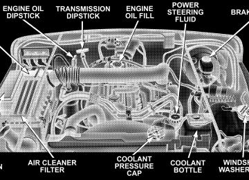
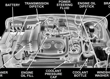
2.4L ENGINE
4.0L ENGINE
MAINTAINING YOUR VEHICLE 267
268 MAINTAINING YOUR VEHICLE
ONBOARD DIAGNOSTIC SYSTEM — OBD II Your vehicle is equipped with a sophisticated onboard diagnostic system called OBD II. This system monitors the performance of the emissions, engine, and automatic transmission control systems. When these systems are operating properly, your vehicle will provide excellent performance and fuel economy, as well as engine emis- sions well within current government regulations. If any of these systems require service, the OBD II system will turn on the “Malfunction Indicator Light.” It will also store diagnostic codes and other information to assist your service technician in making repairs. Al- though your vehicle will usually be drivable and not need towing, see your dealer for service as soon as possible.
CAUTION!
• Prolonged driving with the “Malfunction Indica- tor Light” on could cause further damage to the emission control system. It could also affect fuel economy and driveability. The vehicle must be serviced before any emissions tests can be per- formed. • If the “Malfunction Indicator Light” is flashing while the engine is running, severe catalytic con- verter damage and power loss will soon occur. Immediate service is required.
EMISSIONS INSPECTION AND MAINTENANCE PROGRAMS In some localities, it may be a legal requirement to pass an inspection of your vehicle’s emissions control system. Failure to pass could prevent vehicle registration.
For states which have an I/M (Inspection and Maintenance) requirement, this check verifies the following: the MIL (Malfunction Indicator Lamp) is functioning and is not on when the engine is running, and that the OBD (On Board Diagnostic) system is ready for testing. Normally, the OBD system will be ready. The OBD system may not be ready if your vehicle was recently serviced, if you recently had a dead battery, or a battery replacement. If the OBD system should be determined not ready for the I/M test, your vehicle may fail the test.
MAINTAINING YOUR VEHICLE 269
Your vehicle has a simple ignition key actuated test which you can use prior to going to the test station. To check if your vehicle’s OBD system is ready, you must do the following: 1. Insert your ignition key into the ignition switch. 2. Turn the ignition to the ON position, but do not crank or start the engine. 3. If you crank or start the engine, you will have to start this test over. 4. As soon as you turn your key to the ON position, you will see your MIL symbol come on as part of a normal bulb check. 5. Approximately 15 seconds later, one of two things will happen:
a. The MIL will flash for about 10 seconds and then return to being fully illuminated until you turn off the
270 MAINTAINING YOUR VEHICLE
ignition key or start the engine. This means that your vehicle’s OBD system is not ready and you should not proceed to the I/M station. b. The MIL will not flash at all and will remain fully illuminated until you turn off the ignition key or start the engine. This means that your vehicle’s OBD system is ready and you can proceed to the I/M station.
If your OBD system is not ready, you should see your authorized dealer or repair facility. If your vehicle was recently serviced or had a battery failure or replacement, you may need to do nothing more than drive your vehicle as you normally would in order for your OBD system to update. A recheck with the above test routine may then indicate that the system is now ready. Regardless of whether your vehicle’s OBD system is ready or not ready, if the MIL symbol is illuminated during normal vehicle operation, you should have your
vehicle serviced before going to the I/M station. The I/M station can fail your vehicle because the MIL symbol is on with the engine running.
REPLACEMENT PARTS Use of genuine Mopar威 parts for normal/scheduled maintenance and repairs is highly recommended to in- sure the designed performance. Damage or failures caused by the use of non-Mopar威 parts for maintenance and repairs will not be covered by the manufacturer’s warranty.
DEALER SERVICE Your dealer has the qualified service personnel, special tools and equipment to perform all service operations in an expert manner. Service Manuals are available which include detailed service information for your vehicle. Refer to these manuals before attempting any procedure yourself.
NOTE: systems can result against you.
Intentional tampering with emissions control in civil penalties being assessed
WARNING!
You can be badly injured working on or around a motor vehicle. Do only that service work for which you have the knowledge and the proper equipment. If you have any doubt about your ability to perform a service job, take your vehicle to a competent mechanic.
MAINTAINING YOUR VEHICLE 271
MAINTENANCE PROCEDURES The pages that follow contain the required maintenance services determined by the engineers who designed your vehicle. Besides the maintenance items for which there are fixed maintenance intervals, there are other items that should operate satisfactorily without periodic maintenance. However, if a malfunction of these items does occur, it could adversely affect the engine or vehicle performance. These items should be inspected if a malfunction is observed or suspected. Engine Oil
Checking Oil Level To assure proper lubrication of your vehicle’s engine, the engine oil must be maintained at the correct level. Check the oil level at regular intervals, such as every fuel stop.
272 MAINTAINING YOUR VEHICLE
The best time to check the engine oil level is about 5
minutes after a fully warmed engine is shut off, or before starting the engine after it has sat overnight. Checking the oil while the vehicle is on level ground will improve the accuracy of the oil level readings. Maintain the oil level between the ADD and SAFE markings on the dipstick. Adding 1 U.S. Quart (0.95L) of oil when the reading is at the ADD mark will result in a SAFE reading on these engines.CAUTION!
Overfilling or underfilling the crankcase will cause aeration or loss of oil pressure. This could damage your engine.
Change Engine Oil Road conditions as well as your kind of driving affect the interval at which your oil should be changed. Check the following to determine if any apply to you: • Day or night temperatures are below 32°F (0°C) • Stop and go driving • Extensive engine idling • Driving in dusty conditions • Short trip driving of less than 10 miles (16.2 km)
speeds during hot weather, above 90°F (32°C)
• More than 50% of your driving is at sustained high • Taxi, Police, or delivery service (commercial service) • Trailer towing • Off-road or desert driving • If equipped for and operating with E–85 (ethanol) fuel If ANY of these apply to you, then change your engine oil at every interval shown in schedule “B” of the “Mainte- nance Schedules” section of this manual. If none of these apply to you, then change your engine oil at every interval shown on schedule “A” of the “Main- tenance Schedules” section of this manual NOTE: Under no circumstances should oil change in- tervals exceed 6,000 miles (10 000 km) or 6 months whichever comes first.
MAINTAINING YOUR VEHICLE 273
Engine Oil Selection For best performance and maximum protection for all engines under all types of operating conditions, the manufacturer recommends engine oils that are API Cer- tified and meet the requirements of DaimlerChrysler Material Standard MS-6395. American Petroleum Institute (API) Engine Oil Identification Symbol
This symbol means that the oil has been certified by the American Petroleum Institute (API). The manufacturer only recommends API Certified engine oils.
274 MAINTAINING YOUR VEHICLE
Engine Oil Viscosity (2.4L Engines) SAE 5W-30 engine oil is recommended for all operating temperatures. This engine oil improves low tempera- ture starting and vehicle fuel economy. Your engine oil filler cap shows the recommended engine oil viscosity for your vehicle.
Engine Oil Viscosity (4.0L Engines) SAE 10W-30 engine oil is recommended for all operat- ing temperatures. This engine oil improves low tem- perature starting and vehicle fuel economy. Your engine oil filler cap shows the recommended engine oil vis- cosity for your vehicle.
Lubricants which do not have both, the engine oil certi- fication mark and the correct SAE viscosity grade num- ber should not be used.
Materials Added To Engine Oils The manufacturer strongly recommends against the ad- dition of any additives (other than leak detection dyes) to engine oil. Engine oil is an engineered product and it’s performance may be impaired by supplemental addi- tives. Disposing of Used Engine Oil Care should be taken in disposing of used engine oil from your vehicle. Used oil, indiscriminately discarded, can present a problem to the environment. Contact your authorized dealer, service station, or governmental agency for advice on how and where used oil can be safely discarded in your area. Engine Oil Filter The engine oil filter should be replaced at every engine oil change.