- 2009 Jeep Liberty Owners Manuals
- Jeep Liberty Owners Manuals
- 2011 Jeep Liberty Owners Manuals
- Jeep Liberty Owners Manuals
- 2010 Jeep Liberty Owners Manuals
- Jeep Liberty Owners Manuals
- 2007 Jeep Liberty Owners Manuals
- Jeep Liberty Owners Manuals
- 2008 Jeep Liberty Owners Manuals
- Jeep Liberty Owners Manuals
- 2005 Jeep Liberty Owners Manuals
- Jeep Liberty Owners Manuals
- 2004 Jeep Liberty Owners Manuals
- Jeep Liberty Owners Manuals
- Download PDF Manual
-
activate the trailer brake or apply more vehicle brake pressure prior to releasing the brake pedal. • HSA is not a parking brake. Always apply the parking brake fully when leaving your vehicle. Also, be certain to leave the transmission in PARK. • Failure to follow these warnings can result in a
collision or serious personal injury.
STARTING AND OPERATING 349
Disabling And Enabling HSA This feature can be turned on or turned off. To change the current setting, proceed as follows: For vehicles equipped with the Electronic Vehicle Infor- mation Center (EVIC), refer to “Hill Start Assist,” under ⬙Personal Settings (Customer Programmable Features),” under “Electronic Vehicle Information Center (EVIC)” in “Understanding Your Instrument Panel” for further in- formation. For vehicles not equipped with the EVIC, perform the following steps: NOTE: You must complete Steps 1 through 8 within 90 seconds. 1. Center the steering wheel straight forward). 2. Shift the transmission into PARK.
(front wheels pointing
350 STARTING AND OPERATING 3. Apply the parking brake. 4. Start the engine. 5. Rotate the steering wheel one-half turn to the left. 6. Press the “ESC Off” button located in the lower switch bank below the climate control four times within twenty seconds. The “ESC Off Indicator Light” should turn on and turn off two times. 7. Rotate the steering wheel back to center and then an additional one-half turn to the right. 8. Turn the ignition switch to the OFF position and then back to the ON position. If the sequence was completed properly, the “ESC Off Indicator Light” will blink several times to confirm HSA is disabled. 9. Repeat these steps if you want to return this feature to its previous setting.
Hill Descent Control (HDC) – If Equipped HDC is only intended for low speed off-road driving. HDC maintains vehicle speed while descending hills in off-road driving conditions by applying the brakes when necessary. When enabled, HDC senses the terrain and activates when the vehicle is descending a hill. HDC speed may be adjusted by the driver to suit the driving conditions. The speed corresponds to the transmission gear selected. Approximate HDC Set Speed Gear 1 mph (1.5 km/h) 1st 2nd 3 mph (4.5 km/h) 7.5 mph (12 km/h) DRIVE 1 mph (1.5 km/h) REVERSE NEUTRAL 3 mph (4.5 km/h) However, the driver can override HDC operation by applying the brake to slow the vehicle down below the HDC control speed. If more speed is desired during HDC
control, the accelerator pedal will increase vehicle speed in the usual manner. When either the brake or the accelerator is released, HDC will control the vehicle at the original set speed. NOTE: HDC is available on vehicles equipped with the MP1522 transfer case. • The transfer case must be in 4WD LOW range to • HDC is enabled only when the “Hill Descent Control Indicator Light” in the instrument cluster is on solid. • HDC will NOT activate when the automatic transmis- • HDC will NOT activate on level ground. • HDC will NOT activate at vehicle speeds above
sion is in PARK.
enable HDC.
30 mph (50 km/h).
STARTING AND OPERATING 351
The “Hill Descent” button is located in the lower switch bank below the climate control.Hill Descent Button
Enabling HDC 1. Shift the transfer case into 4WD LOW range. Refer to “Four-Wheel Drive Operation” in “Starting and Operat- ing” for further information.
352 STARTING AND OPERATING 2. Press the “Hill Descent” button. The “Hill Descent Control Indicator Light” in the instrument cluster will turn on solid. If the transfer case is not in 4WD LOW range, NOTE: the “Hill Descent Control Indicator Light” will flash for five seconds and HDC will not be enabled. Disabling HDC 1. Press the “Hill Descent” button or shift the transfer case out of 4WD LOW range. The “Hill Descent Control Indicator” light in the instrument cluster will turn off. Electronic Stability Control (ESC)
This system enhances directional control and stability of the vehicle under various driving conditions. ESC cor- rects for oversteering or understeering of the vehicle by applying the brake of the appropriate wheel to assist in
counteracting the oversteer or understeer condition. En- gine power may also be reduced to help the vehicle maintain the desired path. ESC uses sensors in the vehicle to determine the vehicle path intended by the driver and compares it to the actual path of the vehicle. When the actual path does not match the intended path, ESC applies the brake of the appro- priate wheel to assist in counteracting the oversteer or understeer condition. • Oversteer - when the vehicle is turning more than • Understeer - when the vehicle is turning less than
appropriate for the steering wheel position.
appropriate for the steering wheel position.
The “ESC Activation/Malfunction Indicator Light” lo- cated in the instrument cluster will start to flash as soon as the tires lose traction and the ESC system becomes active. The “ESC Activation/Malfunction Indicator
Light” also flashes when the TCS is active. If the “ESC Activation/Malfunction Indicator Light” begins to flash during acceleration, ease up on the accelerator and apply as little throttle as possible. Be sure to adapt your speed and driving to the prevailing road conditions.
WARNING!
The Electronic Stability Control (ESC) cannot pre- vent the natural laws of physics from acting on the vehicle, nor can it increase the traction afforded by prevailing road conditions. ESC cannot prevent col- lisions, including those resulting from excessive speed in turns, driving on very slippery surfaces, or hydroplaning. The capabilities of an ESC equipped vehicle must never be exploited in a reckless or dangerous manner which could jeopardize the user’s safety or the safety of others.
STARTING AND OPERATING 353
ESC Operating Modes Depending upon model and mode of operation, the ESC system has up to three operating modes: “ESC On” “Partial Off,” and “Full Off.” ESC On – Two-Wheel Drive Vehicles And Four-Wheel Drive Vehicles In 2WD And 4WD High Range This is the normal operating mode for ESC when oper- ating a two-wheel drive vehicle. It is also the normal mode for operating a four-wheel drive vehicle in 2WD or 4WD HIGH range. The ESC system will be in “ESC On” mode whenever the vehicle is started or the transfer case (if equipped) is shifted out of 4WD LOW range. This mode should be used for most driving situations. ESC should only be turned to “Partial Off” or “Full Off” for specific reasons as noted. Refer to “Partial Off” and to “Full Off” for additional information.
354 STARTING AND OPERATING Partial Off – Two-Wheel Drive Vehicles And Four-Wheel Drive Vehicles In 2WD And 4WD High Range The “Partial Off” mode is intended for driving in deep snow, sand, or gravel. This mode raises the threshold for TCS and ESC activation, which allows for more wheel spin than what ESC normally allows. The “ESC Off” button is located in the lower switch bank below the climate control. To enter the “Partial Off” mode, momentarily press the “ESC Off” button and the ⬙ESC Activation/Malfunction Indicator Light” will illu- minate. To turn the ESC on again, momentarily press the ⬙ESC Off⬙ button and the ⬙ESC Activation/Malfunction Indicator Light” will turn off. This will restore the normal “ESC On” mode of operation.
NOTE: To improve the vehicle’s traction when driving with snow chains, or when starting off in deep snow, sand, or gravel, it may be desirable to switch to the “Partial Off” mode by momentarily pressing the “ESC Off” button. Once the situation requiring “Partial Off” mode is overcome, turn ESC back on by momentarily pressing the “ESC Off” button. This may be done while the vehicle is in motion. Full Off – Four-Wheel Drive Vehicles In 4WD High And 4WD Low Range The “Full Off” mode is intended for off-highway and off-road use when ESC stability features could inhibit vehicle maneuverability due to trail conditions. The “ESC Off” button is located in the lower switch bank below the climate control panel. To enter “Full Off” mode, press and hold the “ESC Off” button for five seconds while the vehicle is stopped with the engine running. After the “ESC Activation/
five seconds,
Malfunction Indicator Light” will illuminate and an “ESC OFF” message will appear in the odometer. Press and release the trip odometer button located on the instru- ment cluster to turn off this message. In this mode, ESC and TCS are turned off (except for the “limited slip” feature described in the TCS section) until the vehicle reaches a speed of 40 mph (64 km/k). At speeds over 40 mph (64 km/k), the system automatically switches to “Partial Off” mode, described above. When the vehicle speed returns to less than 35 mph (56 km/h), the ESC system will return to “Full Off” mode. The “ESC Activation/Malfunction Indicator Light” is always illu- minated when ESC is off. To turn ESC on again, momen- tarily press the “ESC Off” button. This will restore the normal “ESC On” mode of operation.
STARTING AND OPERATING 355
NOTE: • “Full Off” is the only operating mode for ESC in 4WD LOW range. The ESC system will be in this mode whenever the vehicle is started in 4WD LOW range or the transfer case is shifted into 4WD LOW range. • The “ESC OFF” message will display and a chime will sound when the shift lever is moved from any position to the PARK position and then moved out of the PARK position. This will occur even if the message was cleared previously.
WARNING!
With the ESC switched off, the enhanced vehicle stability offered by ESC is unavailable. In an emer- gency evasive maneuver, the ESC system will not engage to assist in maintaining stability. “Full Off” mode is only intended for off-highway or off-road use.
356 STARTING AND OPERATING ESC Activation/Malfunction Indicator Light And ESC OFF Indicator Light
The “ESC Activation/Malfunction Indicator Light” in the instrument cluster will come on when the ignition switch is turned to the ON position. It should go out with the engine running. If the “ESC Activation/Malfunction Indicator Light” comes on continuously with the engine running, a malfunction has been detected in the ESC system. If this light remains on after several ignition cycles, and the vehicle has been driven several miles (kilometers) at speeds greater than 30 mph (48 km/h), see your autho- rized dealer as soon as possible to have the problem diagnosed and corrected. The “ESC Activation/Malfunction Indicator Light” (lo- cated in the instrument cluster) starts to flash as soon as the tires lose traction and the ESC system becomes active. The “ESC Activation/Malfunction Indicator Light” also flashes when TCS is active. If the “ESC Activation/
Malfunction Indicator Light” begins to flash during ac- celeration, ease up on the accelerator and apply as little throttle as possible. Be sure to adapt your speed and driving to the prevailing road conditions. NOTE: • The “ESC Activation/Malfunction Indicator Light” and the “ESC OFF Indicator Light” come on momen- tarily each time the ignition switch is turned ON. • Each time the ignition is turned ON, the ESC system • The ESC system will make buzzing or clicking sounds when it is active. This is normal; the sounds will stop when ESC becomes inactive following the maneuver that caused the ESC activation.
will be ON even if it was turned off previously.
The “ESC OFF Indicator Light” indicates the Electronic Stability Control (ESC) is off.
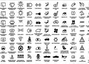
TIRE SAFETY INFORMATION
Tire Markings
1 — U.S. DOT Safety Standards Code (TIN) 2 — Size Designation 3 — Service Description
4 — Maximum Load
5 — Maximum Pressure 6 — Treadwear, Traction and Temperature Grades
STARTING AND OPERATING 357
NOTE: • P (Passenger) - Metric tire sizing is based on U.S. design standards. P-Metric tires have the letter “P” molded into the sidewall preceding the size designa- tion. Example: P215/65R15 95H. • European-Metric tire sizing is based on European design standards. Tires designed to this standard have the tire size molded into the sidewall beginning with the section width. The letter ⬙P⬙ is absent from this tire size designation. Example: 215/65R15 96H. • LT (Light Truck) - Metric tire sizing is based on U.S. design standards. The size designation for LT-Metric tires is the same as for P-Metric tires except for the letters “LT” that are molded into the sidewall preced- ing the size designation. Example: LT235/85R16. • Temporary spare tires are high-pressure compact spares designed for temporary emergency use only.
358 STARTING AND OPERATING
Tires designed to this standard have the letter “T” molded into the sidewall preceding the size designa- tion. Example: T145/80D18 103M.
• High flotation tire sizing is based on U.S. design standards and it begins with the tire diameter molded into the sidewall. Example: 31x10.5 R15 LT.
Tire Sizing Chart
Size Designation:
EXAMPLE:
P = Passenger car tire size based on U.S. design standards ⴖ....blank....ⴖ = Passenger car tire based on European design standards LT = Light truck tire based on U.S. design standards T = Temporary spare tire 31 = Overall diameter in inches (in) 215 = Section width in millimeters (mm) 65 = Aspect ratio in percent (%)
— Ratio of section height to section width of tire
10.5 = Section width in inches (in) R = Construction code
— ⬙R⬙ means radial construction —⬙D⬙ means diagonal or bias construction
15 = Rim diameter in inches (in)
EXAMPLE:
STARTING AND OPERATING 359
Service Description:
95 = Load Index
H = Speed Symbol
— A numerical code associated with the maximum load a tire can carry
— A symbol indicating the range of speeds at which a tire can carry a load corresponding to its load index under certain operating conditions — The maximum speed corresponding to the speed symbol should only be achieved under specified operating conditions (i.e., tire pressure, vehicle loading, road conditions, and posted speed limits)
Load Identification:
ⴖ....blank....ⴖ = Absence of any text on the sidewall of the tire indicates a Standard Load (SL) tire Extra Load (XL) = Extra load (or reinforced) tire Light Load = Light load tire C, D, E = Load range associated with the maximum load a tire can carry at a specified pressure
Maximum Load — Maximum load indicates the maximum load this tire is designed to carry Maximum Pressure — Maximum pressure indicates the maximum permissible cold tire inflation pressure for this tire
360 STARTING AND OPERATING Tire Identification Number (TIN) The TIN may be found on one or both sides of the tire, however, the date code may only be on one side. Tires with white sidewalls will have the full TIN, including the date code, located on the white sidewall side of the tire.
Look for the TIN on the outboard side of black sidewall tires as mounted on the vehicle. If the TIN is not found on the outboard side, then you will find it on the inboard side of the tire.
EXAMPLE:
DOT MA L9 ABCD 0301
DOT = Department of Transportation
— This symbol certifies that the tire is in compliance with the U.S. Department of Transportation tire safety standards and is approved for highway use
MA = Code representing the tire manufacturing location (two digits) L9 = Code representing the tire size (two digits) ABCD = Code used by the tire manufacturer (one to four digits) 03 = Number representing the week in which the tire was manufactured (two digits)
—03 means the 3rd week.
01 = Number representing the year in which the tire was manufactured (two digits)
—01 means the year 2001
— Prior to July 2000, tire manufacturers were only required to have one number to represent the year in which the tire was manufactured. Example: 031 could represent the 3rd week of 1981 or 1991Tire Terminology And Definitions
B-Pillar
Term
Cold Tire Pressure
Maximum Inflation Pressure
Recommended Inflation Pressure
Tire Placard
STARTING AND OPERATING 361
Definition
The vehicle B-Pillar is a structural member of the body located between the front and rear door (of a four-door vehicle) running from the sill to the roof. Cold tire inflation pressure is defined as the tire pressure after the vehicle has not been driven for at least 3 hours, or driven less than 1 mile (1.6 km) after sitting for a three hour period. Inflation pressure is measured in units of PSI (pounds per square inch) or KPa (kilopascals). The maximum inflation pressure is the maximum permissible cold tire inflation pressure for this tire. The max inflation pressure is molded into the sidewall. Vehicle manufacturer’s recommended tire inflation pressure as shown on the tire placard. A paper label permanently attached to the vehicle showing the vehicle’s loading capacity, the original equipment tire size and the recommended inflation pressure.
362 STARTING AND OPERATING Tire Loading And Tire Pressure
Tire Placard Location NOTE: The proper cold tire inflation pressure is listed on the driver’s side B-Pillar.
Tire And Loading Information Placard
Tire and Loading Information Placard
Tire Placard Location
This placard tells you important information about the: 1) number of people that can be carried in the vehicle 2) total weight your vehicle can carry 3) tire size designed for your vehicle 4) cold tire inflation pressures for the front, rear, and spare tires. Loading The vehicle maximum load on the tire must not exceed the load carrying capacity of the tire on your vehicle. You will not exceed the tire’s load carrying capacity if you adhere to the loading conditions, tire size, and cold tire inflation pressures specified on the Tire and Loading Information placard and in the “Vehicle Loading” section of this manual. NOTE: Under a maximum loaded vehicle condition, gross axle weight ratings (GAWRs) for the front and rear
STARTING AND OPERATING 363
axles must not be exceeded. For further information on GAWRs, vehicle loading, and trailer towing, refer to “Vehicle Loading” in this section. To determine the maximum loading conditions of your vehicle, locate the statement “The combined weight of occupants and cargo should never exceed XXX lbs or XXX kg” on the Tire and Loading Information placard. The combined weight of occupants, cargo/luggage and trailer tongue weight (if applicable) should never exceed the weight referenced here. Steps For Determining Correct Load Limit 1. Locate the statement “The combined weight of occu- pants and cargo should never exceed XXX lbs or XXX kg” on your vehicle’s placard. 2. Determine the combined weight of the driver and passengers that will be riding in your vehicle.364 STARTING AND OPERATING 3. Subtract the combined weight of the driver and pas- sengers from XXX lbs or XXX kg. 4. The resulting figure equals the available amount of cargo and luggage load capacity. For example, if “XXX” amount equals 1,400 lbs (635 kg) and there will be five 150 lb (68 kg) passengers in your vehicle, the amount of available cargo and luggage load capacity is 650 lbs (295 kg) (since 5 x 150 = 750, and 1400 – 750 = 650 lbs [295 kg]). 5. Determine the combined weight of luggage and cargo being loaded on the vehicle. That weight may not safely exceed the available cargo and luggage load capacity calculated in Step 4.
6. If your vehicle will be towing a trailer, load from your trailer will be transferred to your vehicle. Consult this manual to determine how this reduces the available cargo and luggage load capacity of your vehicle. NOTE: • The following table shows examples on how to calcu- late total load, cargo/luggage, and towing capacities of your vehicle with varying seating configurations and number and size of occupants. This table is for illustration purposes only and may not be accurate for the seating and load carry capacity of your vehicle. • For the following example, the combined weight of occupants and cargo should never exceed 865 lbs (392 kg).
STARTING AND OPERATING 365
366 STARTING AND OPERATING
WARNING!
Safety
Overloading of your tires is dangerous. Overloading can cause tire failure, affect vehicle handling, and increase your stopping distance. Use tires of the recommended load capacity for your vehicle. Never overload them.
TIRES — GENERAL INFORMATION
Tire Pressure Proper tire inflation pressure is essential to the safe and satisfactory operation of your vehicle. Three primary areas are affected by improper tire pressure:
WARNING!
cause collisions.
sult in over-heating and tire failure.
• Improperly inflated tires are dangerous and can • Under-inflation increases tire flexing and can re- • Over-inflation reduces a tire’s ability to cushion shock. Objects on the road and chuckholes can cause damage that result in tire failure. • Over-inflated or under-inflated tires can affect vehicle handling and can fail suddenly, resulting in loss of vehicle control. • Unequal tire pressures can cause steering prob-
lems. You could lose control of your vehicle.
(Continued)
WARNING! (Continued)
• Unequal tire pressures from one side of the ve- hicle to the other can cause the vehicle to drift to the right or left. • Always drive with each tire inflated to the recom-
mended cold tire inflation pressure.
Economy Improper inflation pressures can cause uneven wear patterns to develop across the tire tread. These abnormal wear patterns will reduce tread life resulting in a need for earlier tire replacement. Under-inflation also increases tire fuel rolling consumption. Ride Comfort And Vehicle Stability Proper tire inflation contributes to a comfortable ride. Over-inflation produces a jarring and uncomfortable ride. Both under-inflation and over-inflation affect the
resistance
resulting
higher
in
STARTING AND OPERATING 367
stability of the vehicle and can produce a feeling of sluggish response or over responsiveness in the steering. Unequal tire pressures can cause erratic and unpredict- able steering response. Unequal tire pressure from side to side may cause the vehicle to drift left or right. Tire Inflation Pressures The proper cold tire inflation pressure is listed on the driver’s side “B” Pillar or rear edge of the driver’s side door. The pressure should be checked and adjusted, as well as inspected for signs of tire wear or visible damage, at least once a month. Use a good quality pocket-type gauge to check tire pressure. Do not make a visual judgement when determining proper inflation. Radial tires may look properly inflated even when they are under-inflated.368 STARTING AND OPERATING
CAUTION!
After inspecting or adjusting the tire pressure, al- ways reinstall the valve stem cap. This will prevent moisture and dirt from entering the valve stem, which could damage it.
Inflation pressures specified on the placard are always cold tire inflation pressure. Cold tire inflation pressure is defined as the tire pressure after the vehicle has not been driven for at least three hours, or driven less than 1 mile (1.6 km) after a three-hour period. The cold tire inflation pressure must not exceed the maximum inflation pres- sure molded into the tire sidewall. Check tire pressures more often if subject to a wide range of outdoor temperatures, as tire pressures vary with temperature changes.
Tire pressures change by approximately 1 psi (7 kPa) per 12°F (7°C) of air temperature change. Keep this in mind when checking tire pressure inside a garage, especially in the winter. Example: If garage temperature = 68°F (20°C) and the outside temperature = 32°F (0°C) then the cold tire inflation pressure should be increased by 3 psi (21 kPa), which equals 1 psi (7 kPa) for every 12°F (7°C) for this outside temperature condition. Tire pressure may increase from 2 to 6 psi (13 to 40 kPa) during operation. DO NOT reduce this normal pressure build-up, or your tire pressure will be too low.
Tire Pressures For High Speed Operation The manufacturer advocates driving at safe speeds within posted speed limits. Where speed limits or condi- tions are such that the vehicle can be driven at high speeds, maintaining correct tire inflation pressure is very important. Increased tire pressure and reduced vehicle loading may be required for high-speed vehicle opera- tion. Refer to original equipment or an authorized tire dealer for recommended safe operating speeds, loading and cold tire inflation pressures.
WARNING!
High speed driving with your vehicle at or above maximum load is dangerous. The added strain on your tires could cause them to fail. You could have a serious collision. Do not drive a vehicle loaded to the maximum capacity at continuous speeds above 75 mph (120 km/h).
STARTING AND OPERATING 369
Radial-Ply Tires
WARNING!
Combining radial ply tires with other types of tires on your vehicle will cause your vehicle to handle poorly. The instability could cause a collision. Al- ways use radial tires in sets of four. Never combine them with other types of tires.
Cuts and punctures in radial tires are repairable only in the tread area because of sidewall flexing. Consult your authorized dealer for radial tire repairs. Spare Tire Matching Original Equipped Tire And Wheel – If Equipped Your vehicle may be equivalent with a spare tire and wheel in look and function as the original equipment tire and wheel found on the front or rear axle of your vehicle. This spare tire may be used in the tire rotation for your
370 STARTING AND OPERATING vehicle. If your vehicle has this option refer to an authorized tire dealer for the recommended tire rotation pattern. If your vehicle is not equipped with an original equip- ment tire and wheel as a spare, a non-matching tempo- rary emergency use spare may be equipped with your vehicle. Temporary use spares are engineered to be used only with your vehicle. Your vehicle may be equipped with one of the following types of non-matching tempo- rary use spares; compact, full size, or limited-use. Do not install more than one non-matching temporary use spare tire/wheel on the vehicle at any given time.
CAUTION!
Because of the reduced ground clearance, do not take your vehicle through an automatic car wash with a compact, full size or limited-use temporary spare installed. Damage to the vehicle may result.
Compact Spare Tire – If Equipped The compact spare is for temporary emergency use only. You can identify if your vehicle is equipped with a compact spare by looking at the spare tire description on the Tire and Loading Information Placard located on the driver’s side door opening or on the sidewall of the tire. Compact spare tire descriptions begin with the letter “T” or “S” preceding the size designation. Example: T145/ 80D18 103M. T, S = Temporary Spare Tire Since this tire has limited tread life the original equip- ment tire should be repaired (or replaced) and reinstalled on your vehicle at the first opportunity. Do not install a wheel cover or attempt to mount a conventional tire on the compact spare wheel, since the wheel is designed specifically for the compact spare tire. Do not install more than one compact spare tire and wheel on the vehicle at any given time.
WARNING!
Compact spares are for temporary emergency use only. With these spares, do not drive more than 50 mph (80 km/h). Temporary use spares have limited tread life. When the tread is worn to the tread wear indicators, the temporary use spare tire needs to be replaced. Be sure to follow the warnings, which apply to your spare. Failure to do so could result in spare tire failure and loss of vehicle control.
Full Size Spare – If Equipped The full size spare is for temporary emergency use only. This tire may look like the original equipped tire on the front or rear axle of your vehicle, but it is not. This spare tire may have limited tread life. When the tread is worn to the tread wear indicators, the temporary use full size spare tire needs to be replaced. Since it is not the same as
STARTING AND OPERATING 371
your original equipment tire, replace (or repair) the original equipment tire and reinstall on the vehicle at the first opportunity. Limited-Use Spare – If Equipped The limited-use spare tire is for temporary emergency use only. This tire is identified by a label located on the limited-use spare wheel. This label contains the driving limitations for this spare. This tire may look like the original equipped tire on the front or rear axle of your vehicle, but it is not. Installation of this limited-use spare tire affects vehicle handling. Since it is not the same as your original equipment tire, replace (or repair) the original equipment tire and reinstall on the vehicle at the first opportunity.372 STARTING AND OPERATING
WARNING!
WARNING!
Limited-use spares are for emergency use only. In- stallation of this limited-use spare tire affects vehicle handling. With this tire, do not drive more than the speed listed on the limit-use spare wheel. Keep inflated to the cold tire inflation pressure listed on your Tire and Loading Information Placard located on the driver’s side door opening. Replace (or repair) the original equipment tire at the first opportunity and reinstall it on your vehicle. Failure to do so could result in loss of vehicle control.
Tire Spinning When stuck in mud, sand, snow, or ice conditions, do not spin your vehicle’s wheels above 30 mph (48 km/h).
Fast spinning tires can be dangerous. Forces gener- ated by excessive wheel speeds may cause tire dam- age or failure. A tire could explode and injure some- one. Do not spin your vehicle’s wheels faster than 30 mph (48 km/h) when you are stuck, and do not let anyone near a spinning wheel no matter what the speed.
Tread Wear Indicators Tread wear indicators are in the original equipment tires to help you in determining when your tires should be replaced.
STARTING AND OPERATING 373
CAUTION!
Proper operation of four-wheel drive vehicles de- pends on tires of equal size, type and circumference on each wheel. Any difference in tire size can cause damage to the transfer case. Tire rotation schedule should be followed to balance tire wear.
Life Of Tire The service life of a tire is dependent upon various factors including but not limited to: • Driving style • Tire pressure • Distance driven
1 — Worn Tire 2 — New Tire These indicators are molded into the bottom of the tread grooves. They will appear as bands when the tread depth becomes 1/16 in (2 mm). When the tread is worn to the tread wear indicators, the tire should be replaced.
374 STARTING AND OPERATING
WARNING!
Tires and the spare tire should be replaced after six years, regardless of the remaining tread. Failure to follow this warning can result in sudden tire failure. You could lose control and have a collision resulting in serious injury or death.
Keep dismounted tires in a cool, dry place with as little exposure to light as possible. Protect tires from contact with oil, grease, and gasoline. Replacement Tires The tires on your new vehicle provide a balance of many characteristics. They should be inspected regularly for wear and correct cold tire inflation pressure. The manu- facturer strongly recommends that you use tires equiva- lent to the originals in size, quality and performance when replacement is needed. (Refer to the paragraph on “Tread Wear Indicators”). Refer to the “Tire and Loading
Information” placard for the size designation of your tire. The Load Index and Speed Symbol for your tire will be found on the original equipment tire sidewall. See the Tire Sizing Chart example found in the Tire Safety Information section of this manual for more information relating to the Load Index and Speed Symbol of a tire. It is recommended to replace the two front tires or two rear tires as a pair. Replacing just one tire can seriously affect your vehicle’s handling. If you ever replace a wheel, make sure that the wheel’s specifications match those of the original wheels. It is recommended you contact your original equipment or an authorized tire dealer with any questions you may have on tire specifications or capability. Failure to use equivalent replacement tires may adversely affect the safety, handling, and ride of your vehicle.
WARNING!
• Do not use a tire, wheel size or rating other than that specified for your vehicle. Some combinations of unapproved tires and wheels may change sus- pension dimensions and performance characteris- tics, resulting in changes to steering, handling, and braking of your vehicle. This can cause unpredict- able handling and stress to steering and suspen- sion components. You could lose control and have a collision resulting in serious injury or death. Use only the tire and wheel sizes with load ratings approved for your vehicle. • Never use a tire with a smaller load index or capacity than what was originally equipped on your vehicle. Using a tire with a smaller load index could result in tire overloading and failure. You could lose control and have a collision.
(Continued)
STARTING AND OPERATING 375
WARNING! (Continued)
• Failure to equip your vehicle with tires having adequate speed capability can result in sudden tire failure and loss of vehicle control.
CAUTION!
Replacing original tires with tires of a different size may result in false speedometer and odometer read- ings.
TIRE CHAINS Use only compact chains, or other traction aids that meet SAE type “Class S” specifications. Chains must be the proper size for the vehicle, as recommended by the chain manufacturer. In addition, only install tire chains on P225/75R16 or smaller tires.
376 STARTING AND OPERATING
CAUTION!
To avoid damage to your vehicle, tires, or chains, observe the following precautions: • Do not use tire chains on vehicles equipped with tires other than P225/75R16 or smaller tires. There may not be adequate clearance for the chains and you are risking structural or body damage to your vehicle. • Because of limited chain clearance between tires and other suspension components, it is important that only chains in good condition are used. Bro- ken chains can cause serious vehicle damage. Stop the vehicle immediately if noise occurs that could suggest chain breakage. Remove the damaged parts of the chain before further use.
(Continued)
CAUTION! (Continued)
• Install chains on the rear wheels as tightly as possible and then retighten after driving about 1⁄2
mile (0.8 km).bumps, especially with a loaded vehicle.
• Do not exceed 45 mph (72 km/h). • Drive cautiously and avoid severe turns and large • Use on Rear Wheels only. • Do not drive for a prolonged period on dry pave- • Observe the tire chain manufacturer’s instructions on method of installation, operating speed, and conditions for use. Always use the lower sug- gested operating speed of the chain manufacturer if different from the speed recommended by the manufacturer.
ment.
These cautions apply to all chain traction devices, includ- ing link and cable (radial) chains.
TIRE ROTATION RECOMMENDATIONS The tires on the front and rear of your vehicle operate at different loads and perform different steering, handling, and braking functions. For these reasons, they wear at unequal rates. These effects can be reduced by timely rotation of tires. The benefits of rotation are especially worthwhile with aggressive tread designs such as those on On/Off Road type tires. Rotation will increase tread life, help to main- tain mud, snow, and wet traction levels, and contribute to a smooth, quiet ride. Refer to the “Maintenance Schedule” for the proper maintenance intervals. The reasons for any rapid or unusual wear should be corrected prior to rotation being performed.
STARTING AND OPERATING 377
The suggested rotation method is the “forward-cross” shown in the following diagram. This rotation pattern does not apply to some directional tires that must not be reversed.Tire Rotation
378 STARTING AND OPERATING
CAUTION!
Proper operation of four-wheel drive vehicles de- pends on tires of equal size, type and circumference on each wheel. Any difference in tire size can cause damage to the transfer case. Tire rotation schedule should be followed to balance tire wear.
TIRE PRESSURE MONITOR SYSTEM (TPMS) The Tire Pressure Monitor System (TPMS) will warn the driver of a low tire pressure based on the vehicle recom- mended cold placard pressure. The tire pressure will vary with temperature by about 1 psi (6.9 kPa) for every 12°F (6.5°C). This means that when the outside temperature decreases, the tire pressure will decrease. Tire pressure should always be set based on cold inflation tire pressure. This is defined as the tire pressure after the vehicle has not been driven for at least three hours, or driven less than 1 mile (1.6 km) after a
three hour period. The cold tire inflation pressure must not exceed the maximum inflation pressure molded into the tire sidewall. Refer to “Tires – General Information” in “Starting and Operating” for information on how to properly inflate the vehicle’s tires. The tire pressure will also increase as the vehicle is driven. This is normal and there should be no adjustment for this increased pres- sure. The TPMS will warn the driver of a low tire pressure if the tire pressure falls below the low-pressure warning limit for any reason, including low temperature effects and natural pressure loss through the tire. The TPMS will continue to warn the driver of low tire pressure as long as the condition exists, and will not turn off until the tire pressure is at or above the recommended cold placard pressure. Once the low tire pressure warn- ing (Tire Pressure Monitoring Telltale Light) illuminates, you must increase the tire pressure to the recommended
cold placard pressure in order for the “Tire Pressure Monitoring Telltale Light” to turn off. The system will automatically update and the “Tire Pressure Monitoring Telltale Light” will turn off once the system receives the updated tire pressures. The vehicle may need to be driven for up to 20 minutes above 15 mph (24 km/h) in order for the TPMS to receive this information. For example, your vehicle may have a recommended cold (parked for more than three hours) placard pressure of 33 psi (227 kPa). If the ambient temperature is 68°F (20°C) and the measured tire pressure is 28 psi (193 kPa), a temperature drop to 20°F (-7°C) will decrease the tire pressure to approximately 24 psi (165 kPa). This tire pressure is low enough to turn ON the “Tire Pressure Monitoring Telltale Light.” Driving the vehicle may cause the tire pressure to rise to approximately 28 psi (193 kPa), but the “Tire Pressure Monitoring Telltale Light” will still be on. In this situation, the “Tire Pressure Monitoring
STARTING AND OPERATING 379
Telltale Light” will turn off only after the tires are inflated to the vehicle’s recommended cold placard pressure value.CAUTION!
• The TPMS has been optimized for the original equipment tires and wheels. TPMS pressures and warning have been established for the tire size equipped on your vehicle. Undesirable system operation or sensor damage may result when us- ing replacement equipment that is not of the same size, type, and/or style. Aftermarket wheels can cause sensor damage. Do not use aftermarket tire sealants or balance beads if your vehicle is equipped with a TPMS, as damage to the sensors may result.
(Continued)
380 STARTING AND OPERATING
CAUTION! (Continued)
• After inspecting or adjusting the tire pressure, always reinstall the valve stem cap. This will prevent moisture and dirt from entering the valve stem, which could damage the Tire Pressure Moni- toring Sensor.
NOTE: • The TPMS is not intended to replace normal tire care and maintenance, or to provide warning of a tire failure or condition. • The TPMS should not be used as a tire pressure gauge • Driving on a significantly under-inflated tire causes the tire to overheat and can lead to tire failure. Under-inflation also reduces fuel efficiency and tire tread life, and may affect the vehicle’s handling and stopping ability.
while adjusting your tire pressure.
• The TPMS is not a substitute for proper tire mainte- nance, and it is the driver’s responsibility to maintain correct tire pressure using an accurate tire pressure gauge, even if under-inflation has not reached the level to trigger illumination of the “Tire Pressure Monitoring Telltale Light.” • Seasonal temperature changes will affect tire pressure, and the TPMS will monitor the actual tire pressure in the tire.
Base System The Tire Pressure Monitor System (TPMS) uses wireless technology with wheel rim mounted electronic sensors to monitor tire pressure levels. Sensors, mounted to each wheel as part of the valve stem, transmit tire pressure readings to the receiver module. It is particularly important for you to check the NOTE: tire pressure in all of the tires on your vehicle monthly and to maintain the proper pressure.
The TPMS consists of the following components: • Receiver Module • Four Tire Pressure Monitoring Sensors • Tire Pressure Monitoring Telltale Light The matching full-size spare wheel and tire assembly (if equipped) has a tire pressure monitoring sensor. The matching full-size spare can be used in place of any of the four road tires. The TPMS will only monitor the pressure in the full-size spare when it is used in place of a road tire. Otherwise, a spare with a pressure below the low- pressure limit will not cause the “Tire Pressure Monitor- ing Telltale Light” to illuminate or the chime to sound.
STARTING AND OPERATING 381
Tire Pressure Monitoring Low Pressure Warnings
The “Tire Pressure Monitoring Telltale Light” will illuminate in the instrument cluster and a chime will sound when tire pressure is low in one or more of the four active road tires. Should this occur, you should stop as soon as possible, check the inflation pressure of each tire on your vehicle, and inflate each tire to the vehicle’s recommended cold placard pressure value. Once the system receives the updated tire pres- sures, the system will automatically update and the “Tire Pressure Monitoring Telltale Light” will turn off. The vehicle may need to be driven for up to 20 minutes above 15 mph (24 km/h) in order for the TPMS to receive this information. Check TPMS Warning When a system fault is detected, the “Tire Pressure Monitoring Telltale Light” will flash on and off for 75 seconds and then remain on solid. The system fault will also sound a chime. If the ignition key is cycled, this
382 STARTING AND OPERATING sequence will repeat, providing the system fault still exists. The “Tire Pressure Monitoring Telltale Light” will turn off when the fault condition no longer exists. A system fault can occur due to any of the following: 1. Jamming due to electronic devices or driving next to facilities emitting the same radio frequencies as the TPMS sensors. 2. Installing some form of aftermarket window tinting that affects radio wave signals. 3. Lots of snow or ice around the wheels or wheel housings. 4. Using tire chains on the vehicle. 5. Using wheels/tires not equipped with TPMS sensors.
Vehicles With Full-Size Spare 1. The matching full-size spare wheel and tire assembly has a tire pressure monitoring sensor that can be moni- tored by the TPMS. 2. If you install the full-size spare in place of a road tire that has a pressure below the low-pressure warning limit, a chime will sound and the “TPMS Telltale Light” will turn on upon the next ignition key cycle. 3. Driving the vehicle for up to 20 minutes above 15 mph (24 km/h) will turn off the “TPMS Telltale Light,” as long as no tire pressure is below the low-pressure warning limit in any of the four active road tires. Vehicles With Compact Spare 1. The compact spare tire does not have a tire pressure monitoring sensor. Therefore, the TPMS will not monitor the pressure in the compact spare tire.
2. If you install the compact spare tire in place of a road tire that has a pressure below the low-pressure warning limit, a chime will sound and the “TPMS Telltale Light” will turn on upon the next ignition key cycle. 3. After driving the vehicle for up to 20 minutes above 15 mph (24 km/h), the “TPMS Telltale Light” will flash on and off for 75 seconds and then remain on solid. 4. For each subsequent ignition key cycle, a chime will sound and the “TPMS Telltale Light” will flash on and off for 75 seconds and then remain on solid. 5. Once you repair or replace the original road tire and reinstall it on the vehicle in place of the compact spare, the TPMS will update automatically and the “TPMS Telltale Light” will turn off, as long as no tire pressure is below the low-pressure warning limit in any of the four active road tires. The vehicle may need to be driven for up to 20 minutes above 15 mph (24 km/h) in order for the TPMS to receive this information.
STARTING AND OPERATING 383
Premium System – If Equipped The Tire Pressure Monitor System (TPMS) uses wireless technology with wheel rim mounted electronic sensors to monitor tire pressure levels. Sensors, mounted to each wheel as part of the valve stem, transmit tire pressure readings to the receiver module. It is particularly important for you to check the NOTE: tire pressure in all of the tires on your vehicle monthly and to maintain the proper pressure. The TPMS consists of the following components: • Receiver Module • Four Tire Pressure Monitoring Sensors • Three Trigger Modules (mounted in three of the four
wheel-wells)
384 STARTING AND OPERATING
• Various Tire Pressure Monitoring System messages, which display in the Electronic Vehicle Information Center (EVIC)
• Tire Pressure Monitoring Telltale Light The matching full size spare wheel and tire assembly (if equipped) has a tire pressure monitoring sensor. The full size spare can be used in place of any of the four road tires. A spare with a pressure below the low-pressure limit will not cause the “Tire Pressure Monitoring Telltale Light” to illuminate or the chime to sound. However, it will cause a “SPARE LOW PRESSURE” message to display in the EVIC.
Tire Pressure Monitoring Low Pressure Warnings
The “Tire Pressure Monitoring Telltale Light” will illuminate in the instrument cluster and a chime will sound when tire pressure is low in one or more of the four active road tires. In addition, the Electronic Vehicle Information Center (EVIC) will display a graphic showing the pressure values of each tire with the low tire pressure values flashing.
STARTING AND OPERATING 385
seconds and then display dashes (- -) in place of the pressure value to indicate which sensor is not being received.Should this occur, you should stop as soon as possible and inflate the tires with low pressure (those flashing in the EVIC graphic) to the vehicle’s recommended cold placard pressure value. Once the system receives the updated tire pressures, the system will automatically update, the graphic display in the EVIC will stop flash- ing, and the “Tire Pressure Monitoring Telltale Light” will turn off. The vehicle may need to be driven for up to 20 minutes above 15 mph (24 km/h) in order for the TPMS to receive this information. Check TPMS Warning When a system fault is detected, the “Tire Pressure Monitoring Telltale Light” will flash on and off for 75 seconds and then remain on solid. The system fault will also sound a chime. In addition, the EVIC will display a ⬙CHECK TPM SYSTEM⬙ message for three
386 STARTING AND OPERATING If the ignition key is cycled, this sequence will repeat, providing the system fault still exists. If the system fault no longer exists, the “Tire Pressure Monitoring Telltale Light” will no longer flash, and the ⬙CHECK TPM SYSTEM⬙ message will no longer display, and a pressure value will display in place of the dashes. A system fault can occur due to any of the following: 1. Jamming due to electronic devices or driving next to facilities emitting the same radio frequencies as the TPMS sensors. 2. Installing some form of aftermarket window tinting that affects radio wave signals. 3. Lots of snow or ice around the wheels or wheel housings. 4. Using tire chains on the vehicle. 5. Using wheels/tires not equipped with TPMS sensors.
Vehicles With Full-Size Spare 1. The matching full size spare wheel and tire assembly has a tire pressure monitoring sensor that can be moni- tored by the TPMS. 2. If you install the full size spare in place of a road tire that has a pressure below the low-pressure warning limit, a chime will sound and the “TPMS Telltale Light” will turn on upon the next ignition key cycle. In addition, the EVIC will display a Low Pressure message and a graphic showing the low tire pressure value flashing. 3. After driving the vehicle for up to 20 minutes above 15 mph (24 km/h) the “TPMS Telltale Light” will turn OFF, as long as no tire pressure is below the low-pressure warning limit in any of the four active road tires. 4. The EVIC will display a graphic showing the tire pressure value in place of the flashing low tire pressure
value. The EVIC will also display a “SPARE LOW PRESSURE” message to remind you to service the flat tire. Vehicles With Compact Spare 1. The compact spare tire does not have a tire pressure monitoring sensor. Therefore, the TPMS will not monitor the pressure in the compact spare tire. 2. If you install the compact spare tire in place of a road tire that has a pressure below the low-pressure warning limit, upon the next ignition key cycle, the “TPMS Telltale Light” will remain on and a chime will sound. In addition, the graphic in the EVIC will still display a flashing pressure value. 3. After driving the vehicle for up to 20 minutes above 15 mph (24 km/h), the “TPMS Telltale Light” will flash on and off for 75 seconds and then remain on solid. In
STARTING AND OPERATING 387
addition, the EVIC will display a ⬙CHECK TPM SYS- TEM⬙ message for three seconds and then display dashes (- -) in place of the pressure value. 4. For each subsequent ignition key cycle, a chime will sound, the “TPMS Telltale Light” will flash on and off for 75 seconds and then remain on solid, and the EVIC will display a ⬙CHECK TPM SYSTEM⬙ message for three seconds and then display dashes (- -) in place of the pressure value. 5. Once you repair or replace the original road tire and reinstall it on the vehicle in place of the compact spare, the TPMS will update automatically. In addition, the “TPMS Telltale Light” will turn off and the graphic in the EVIC will display a new pressure value instead of dashes (- -), as long as no tire pressure is below the low-pressure warning limit in any of the four active road tires. The388 STARTING AND OPERATING vehicle may need to be driven for up to 20 minutes above 15 mph (24 km/h) in order for the TPMS to receive this information. General Information This device complies with Part 15 of the FCC rules and RSS 210 of Industry Canada. Operation is subject to the following conditions: • This device may not cause harmful interference. • This device must accept any interference received, including interference that may cause undesired operation.
The tire pressure sensors are covered under one of the following licenses:
United States . . . . . . . . . . . . . . . . . . . . . KR5S120123
Canada . . . . . . . . . . . . . . . . . . . . . . . . 2671-S120123FUEL REQUIREMENTS
All engines are designed to meet all emis- sions regulations and provide excellent fuel economy and performance when us- ing high quality unleaded “regular” gaso- line having an octane rating of 87. The use of premium gasoline is not recommended, as it will not provide any benefit over regular gasoline in these engines. Light spark knock at low engine speeds is not harmful to your engine. However, continued heavy spark knock at high speeds can cause damage and immediate service is required. Poor quality gasoline can cause problems such as hard starting, stalling, and hesitations. If you experi- ence these symptoms, try another brand of gasoline before considering service for the vehicle.
Over 40 auto manufacturers worldwide have issued and endorsed consistent gasoline specifications (the World- wide Fuel Charter, WWFC) which define fuel properties necessary to deliver enhanced emissions, performance, and durability for your vehicle. The manufacturer recom- mends the use of gasoline that meets the WWFC speci- fications if they are available. Reformulated Gasoline Many areas of the country require the use of cleaner burning gasoline referred to as “Reformulated Gasoline.” Reformulated gasolines contain oxygenates, and are spe- cifically blended to reduce vehicle emissions and im- prove air quality. The manufacturer supports the use of reformulated gaso- lines. Properly blended reformulated gasolines will pro- vide excellent performance and durability of engine and fuel system components.
STARTING AND OPERATING 389
Gasoline/Oxygenate Blends Some fuel suppliers blend unleaded gasoline with oxy- genates such as Ethanol. Fuels blended with oxygenates may be used in your vehicle.
CAUTION!
DO NOT use gasoline containing Methanol or gaso- line containing more than 10% Ethanol. Use of these blends may result in starting and driveability prob- lems, damage critical fuel system components, cause emissions to exceed the applicable standard, and/or cause the “Malfunction Indicator Light” to illumi- nate. Pump labels should clearly communicate if a fuel contains greater than 10% Ethanol.
Problems that result from using gasoline containing Methanol or gasoline containing more than 10% Ethanol are not the responsibility of the manufacturer and may not be covered under warranty.
390 STARTING AND OPERATING E-85 Usage In Non-Flex Fuel Vehicles Non-FFV vehicles are compatible with gasoline contain- ing 10% ethanol (E10). Gasoline with higher ethanol content may void the vehicle’s warranty. If a Non-FFV vehicle is inadvertently fueled with E-85
fuel, the engine will have some or all of these symptoms: • operate in a lean mode • OBD II “Malfunction Indicator Light” on • poor engine performance • poor cold start and cold drivability • increased risk for fuel system component corrosion To fix a Non-FFV vehicle inadvertently fueled once with E-85 perform the following: • drain the fuel tank (see your authorized dealer) • change the engine oil and oil filter• disconnect and reconnect the battery to reset the
engine controller memory
More extensive repairs will be required for prolonged exposure to E-85 fuel. MMT In Gasoline MMT is a manganese containing metallic additive that is blended into some gasoline to increase octane. Gasoline blended with MMT provides no performance advantage beyond gasoline of the same octane number without MMT. Gasoline blended with MMT reduces spark plug life and reduces emission system performance in some vehicles. The manufacturer recommends that gasoline without MMT be used in your vehicle. The MMT content of gasoline may not be indicated on the gasoline pump; therefore, you should ask your gasoline retailer whether the gasoline contains MMT. It is even more important to look for gasolines without MMT in Canada, because
MMT can be used at levels higher than those allowed in the United States. MMT is prohibited in Federal and California reformulated gasoline. Materials Added To Fuel All gasoline sold in the United States is required to contain effective detergent additives. Use of additional detergents or other additives is not needed under normal conditions and they would result in additional cost. Therefore, you should not have to add anything to the fuel. Fuel System Cautions
CAUTION!
Use the following guidelines to maintain your vehi- cle’s performance:
(Continued)
STARTING AND OPERATING 391
CAUTION! (Continued)
• The use of leaded gas is prohibited by Federal law. Using leaded gasoline can impair engine perfor- mance, and damage the emission control system. • An out-of-tune engine, or certain fuel or ignition malfunctions, can cause the catalytic converter to overheat. If you notice a pungent burning odor or some light smoke, your engine may be out of tune or malfunctioning and may require immediate service. Contact your authorized dealer for service assistance. • The use of fuel additives, which are now being sold as octane enhancers, is not recommended. Most of these products contain high concentra- tions of methanol. Fuel system damage or vehicle performance problems resulting from the use of such fuels or additives is not the responsibility of the manufacturer.
Intentional tampering with emissions control in civil penalties being assessed
392 STARTING AND OPERATING NOTE: systems can result against you. Carbon Monoxide Warnings
WARNING!
Carbon monoxide (CO) in exhaust gases is deadly. Follow the precautions below to prevent carbon monoxide poisoning.
(Continued)
WARNING! (Continued)
• Do not inhale exhaust gases. They contain carbon monoxide, a colorless and odorless gas, which can kill. Never run the engine in a closed area, such as a garage, and never sit in a parked vehicle with the engine running for an extended period. If the vehicle is stopped in an open area with the engine running for more than a short period, adjust the ventilation system to force fresh, outside air into the vehicle. • Guard against carbon monoxide with proper maintenance. Have the exhaust system inspected every time the vehicle is raised. Have any abnor- mal conditions repaired promptly. Until repaired, drive with all side windows fully open. • Keep the liftgate closed when driving your vehicle to prevent carbon monoxide and other poisonous exhaust gases from entering the vehicle.
ADDING FUEL
Fuel Filler Cap (Gas Cap) The gas cap is located behind the fuel filler door, on the driver’s side of the vehicle. If the gas cap is lost or damaged, be sure the replacement cap has been designed for use with this vehicle.
STARTING AND OPERATING 393
CAUTION!
• Damage to the fuel system or emission control system could result from using an improper fuel cap (gas cap). A poorly fitting cap could let impu- rities into the fuel system. Also, a poorly fitting aftermarket cap can cause the “Malfunction Indi- cator Light (MIL)” to illuminate, due to fuel vapors escaping from the system. • A poorly fitting gas cap may cause the MIL to turn • To avoid fuel spillage and overfilling, do not “top
on.
off” the fuel tank after filling.
Fuel Filler Cap
394 STARTING AND OPERATING
WARNING!
• Never have any smoking materials lit in or near the vehicle when the gas cap is removed or the tank is being filled. • Never add fuel when the engine is running. This is in violation of most state and federal fire regula- tions and may cause the MIL to turn on. • A fire may result if gasoline is pumped into a portable container that is inside of a vehicle. You could be burned. Always place gas containers on the ground while filling.
tank is full.
NOTE: • When the fuel nozzle “clicks” or shuts off, the fuel • Tighten the gas cap about one quarter turn until you hear one click. This is an indication that the cap is properly tightened.
• If the gas cap is not tightened properly, the MIL will come on. Be sure the gas cap is tightened every time the vehicle is refueled.
Loose Fuel Filler Cap Message If the vehicle diagnostic system determines that the fuel filler cap is loose, improperly installed, or damaged, a gASCAP” message will display in the odometer or a “CHECK GASCAP” message will be displayed in the Electronic Vehicle Information Center (EVIC). Refer to “Electronic Vehicle Information Center (EVIC)” in “Un- derstanding Your Instrument Panel” for further review. Tighten the fuel filler cap until a “clicking” sound is heard. This is an indication that the fuel filler cap is properly tightened. Refer to “Onboard Diagnostic Sys- tem” further information.
in “Maintaining Your Vehicle”
for
VEHICLE LOADING
Certification Label As required by National Highway Traffic Safety Admin- istration regulations, your vehicle has a certification label affixed to the driver’s side door or B-Pillar. This label contains the month and year of manufacture, Gross Vehicle Weight Rating (GVWR), Gross Axle Weight Rating (GAWR) front and rear, and Vehicle Identification Number (VIN). A Month-Day-Hour (MDH) number is included on this label and indicates the month, day, and hour of manufacture. The bar code that appears on the bottom of the label is your VIN.
STARTING AND OPERATING 395
Gross Vehicle Weight Rating (GVWR) The GVWR is the total permissible weight of your vehicle including driver, passengers, vehicle, options, trailer tongue weight, and cargo. The label also specifies maxi- mum capacities of front and rear axle systems (GAWR). Total load must be limited, so GVWR, and front and rear GAWR are not exceeded. Payload The payload of a vehicle is defined as the allowable load weight a truck or any given vehicle can carry, including the weight of the driver, all passengers, options and cargo. Gross Axle Weight Rating (GAWR) The GAWR is the maximum permissible load on the front and rear axles. The load must be distributed in the cargo area so that the GAWR of each axle is not exceeded.
396 STARTING AND OPERATING Each axle’s GAWR is determined by the components in the system with the lowest load carrying capacity (axle, springs, tires, or wheels). Heavier axles or suspension components, sometimes specified by purchasers for in- creased durability, does not necessarily increase the ve- hicle’s GVWR. Tire Size The tire size on the label represents the actual tire size on your vehicle. Replacement tires must be equal to the load capacity of this tire size. Rim Size This is the rim size that is appropriate for the tire size listed. Inflation Pressure This is the cold tire inflation pressure for your vehicle for all loading conditions up to full GAWR.
Curb Weight The curb weight of a vehicle is defined as the total weight of the vehicle with all fluids, including vehicle fuel, at full capacity conditions, and with no occupants or cargo loaded into the vehicle. The front and rear curb weight values are determined by weighing your vehicle on a commercial scale before any occupants or cargo are added. Loading The actual total weight and the weight of the front and rear of your vehicle at the ground can best be determined by weighing it when it is loaded and ready for operation. The entire vehicle should first be weighed on a commer- cial scale to ensure that the GVWR has not been ex- ceeded. The weight on the front and rear of the vehicle should then be determined separately to be sure that the load is properly distributed over front and rear axle. Weighing the vehicle may show that the GAWR of either
the front or rear axles has been exceeded, but the total load is within the specified GVWR. If so, weight must be shifted from front to rear, or rear to front, as appropriate until the specified weight limitations are met. Store the heavier items down low and be sure that the weight is distributed equally. Stow all loose items securely before driving. Improper weight distributions can have an adverse affect on the way your vehicle steers and handles, and the way the brakes operate.
CAUTION!
Do not load your vehicle any heavier than the GVWR or the maximum front and rear GAWR. If you do, parts on your vehicle can break, or it can change the way your vehicle handles. This could cause you to lose control. Also, overloading can shorten the life of your vehicle.
STARTING AND OPERATING 397
TRAILER TOWING In this section, you will find safety tips and information on limits to the type of towing you can reasonably do with your vehicle. Before towing a trailer, carefully review this information to tow your load as efficiently and safely as possible. To maintain warranty coverage, follow the requirements and recommendations in this manual concerning ve- hicles used for trailer towing. Common Towing Definitions The following trailer towing related definitions will assist you in understanding the following information: Gross Vehicle Weight Rating (GVWR) The GVWR is the total allowable weight of your vehicle. This includes driver, passengers, cargo, and tongue weight. The total load must be limited so that you do not
398 STARTING AND OPERATING exceed the GVWR. Refer to “Vehicle Loading/Vehicle Certification Label” in “Starting and Operating” for further information. Gross Trailer Weight (GTW) The GTW is the weight of the trailer plus the weight of all cargo, consumables, and equipment (permanent or tem- porary) loaded in or on the trailer in its ⬙loaded and ready for operation⬙ condition. The recommended way to measure GTW is to put your fully loaded trailer on a vehicle scale. The entire weight of the trailer must be supported by the scale.
WARNING!
If the Gross Trailer Weight (GTW) is 3,500 lbs (1 587 kg) or more, it is mandatory to use a weight-distributing hitch to ensure stable handling of your vehicle. If you use a standard weight- carrying hitch, you could lose control of your vehicle and cause a collision.
Gross Combination Weight Rating (GCWR) The GCWR is the total permissible weight of your vehicle and trailer when weighed in combination. NOTE: The GCWR rating includes a 150 lbs (68 kg) allowance for the presence of a driver. Gross Axle Weight Rating (GAWR) The GAWR is the maximum capacity of the front and rear axles. Distribute the load over the front and rear axles evenly. Make sure that you do not exceed either front or rear GAWR. Refer to “Vehicle Loading/Vehicle Certifica- tion Label” in “Starting and Operating” for further information.
WARNING!
It is important that you do not exceed the maximum front or rear GAWR. A dangerous driving condition can result if either rating is exceeded. You could lose control of the vehicle and have a collision.
Tongue Weight (TW) The tongue weight is the downward force exerted on the hitch ball by the trailer. In most cases, it should not be less than 10% or more than 15% of the trailer load. You must consider this as part of the load on your vehicle. Frontal Area The frontal area is the maximum height multiplied by the maximum width of the front of a trailer. Trailer Sway Control – Mechanical The trailer sway control is a telescoping link that can be installed between the hitch receiver and the trailer tongue that typically provides adjustable friction associated with the telescoping motion to dampen any unwanted trailer swaying motions while traveling. Weight-Carrying Hitch A weight-carrying hitch supports the trailer tongue weight, just as if it were luggage located at a hitch ball or some other connecting point of the vehicle. These kinds
STARTING AND OPERATING 399
of hitches are the most popular on the market today and they are commonly used to tow small- and medium- sized trailers. Weight-Distributing Hitch A weight-distributing system works by applying lever- age through spring (load) bars. They are typically used for heavier loads, to distribute trailer tongue weight to the tow vehicle’s front axle and the trailer axle(s). When used in accordance with the manufacturers’ directions, it provides for a more level ride, offering more consistent steering and brake control thereby enhancing towing safety. The addition of a friction/hydraulic sway control also dampens sway caused by traffic and crosswinds and contributes positively to tow vehicle and trailer stability. Trailer sway control and a weight distributing (load equalizing) hitch are recommended for heavier Tongue Weights (TW) and may be required depending on Vehicle and Trailer configuration/loading to comply with Gross Axle Weight Rating (GAWR) requirements.400 STARTING AND OPERATING
WARNING!
• An improperly adjusted Weight Distributing Hitch system may reduce handling, stability, brak- ing performance, and could result in a collision. • Weight Distributing Systems may not be compat- ible with Surge Brake Couplers. Consult with your hitch and trailer manufacturer or a reputable Rec- reational additional information.
Vehicle
dealer
for
Without Weight Distributing Hitch (Incorrect)
STARTING AND OPERATING 401
With Weight Distributing Hitch (Correct)
Improper Adjustment of Weight-Distributing Hitch
(Incorrect)
402 STARTING AND OPERATING Trailer Hitch Classification Your vehicle is capable of towing trailers up to 2,000 lbs (907 kg) without added equipment or alterations to the standard equipment. Your vehicle may be factory equipped for safe towing of trailers weighing over 2,000 lbs (907 kg) with the optional Trailer Tow Prep Package. See your authorized dealer for package content. The following chart provides the industry standard for the maximum trailer weight a given trailer hitch class can tow. This should be used to assist you in selecting the correct trailer hitch for your intended towing condition. Refer to the “Trailer Towing Weights (Maximum Trailer Weight Ratings)” chart for the Max. GTW towable for your given drivetrain.
Trailer Hitch Classification Definitions
Class
Max. Trailer Hitch Industry
Standards
2,000 lbs (907 kg) 3,500 lbs (1 587 kg)
5,000 lbs (2 268 kg) 10,000 lbs (4 540 kg)
Class I - Light Duty Class II - Medium Duty Class III - Heavy Duty Class IV - Extra Heavy Duty Refer to the “Trailer Towing Weights (Maximum Trailer Weight Ratings)” chart for the Maximum Gross Trailer Weight (GTW) towable for your given drivetrain. All trailer hitches should be professionally installed on your vehicle.
STARTING AND OPERATING 403
Trailer Towing Weights (Maximum Trailer Weight Ratings) The following chart provides the maximum trailer weight ratings towable for your given drivetrain.
Engine/
Transmission 3.7L/Automatic 3.7L/Automatic
Model
Frontal Area
Max. GTW (Gross Trailer
Wt.)
Max. Tongue Wt. (See
Note)
4x2
4x432 sq ft (2.97 sq m) 32 sq ft (2.97 sq m)
2,000 lbs (907 kg) 2,000 lbs (907 kg)
200 lbs (91 kg) 200 lbs (91 kg)
Refer to local laws for maximum trailer towing speeds. NOTE: The trailer tongue weight must be considered as part of the combined weight of occupants and cargo (ie. the GVWR), and the GVWR should never exceed the weight referenced on the Tire and Loading Infor- mation placard. Refer to “Tire Safety Information” in “Starting and Operating” for further information.
404 STARTING AND OPERATING When Towing Trailers With Gross Trailer Weight (GTW) Between 3,500 Lbs (1 588 kg) And 5,000 Lbs (2 268 kg) The following chart provides maximum trailer weight ratings towable for the following engine/transmission combinations, ONLY if using a weight distributing hitch.
Model
Frontal Area
64 sq ft (5.94 sq m)
Max. GTW
(Gross Trailer Wt.) 5,000 lbs (2 268 kg)
Max. Tongue Wt.
(See Note)
500 lbs (227 kg)
64 sq ft (5.94 sq m)
5,000 lbs (2 268 kg)
500 lbs (227 kg)
Refer to local laws for maximum trailer towing speeds. NOTE: The trailer tongue weight must be considered as part of the combined weight of occupants and cargo (ie. the GVWR), and the GVWR should never exceed the weight referenced on the Tire and Loading Infor- mation placard. Refer to “Tire Safety Information” in “Starting and Operating” for further information.
Engine/
Transmission 3.7L/Automatic w/Trailer Tow
Package
3.7L/Automatic w/Trailer Tow
package
4x2
4x4
Trailer And Tongue Weight Always load a trailer with 60% to 65% of the weight in the front of the trailer. This places 10% to 15% of the Gross Trailer Weight (GTW) on the tow hitch of your vehicle. Loads balanced over the wheels or heavier in the rear can cause the trailer to sway severely side to side which will cause loss of control of vehicle and trailer. Failure to load trailers heavier in front is the cause of many trailer collisions.
STARTING AND OPERATING 405
Consider the following items when computing the weight on the rear axle of the vehicle: • The tongue weight of the trailer. • The weight of any other type of cargo or equipment • The weight of the driver and all passengers.
put in or on your vehicle.
406 STARTING AND OPERATING NOTE: Remember that everything put into or on the trailer adds to the load on your vehicle. Also, additional factory-installed options, or authorized dealer-installed options, must be considered as part of the total load on your vehicle. Refer to the “Tire and Loading Information” placard for the maximum combined weight of occupants and cargo for your vehicle. Towing Requirements To promote proper break-in of your new vehicle drive- train components, the following guidelines are recom- mended:
CAUTION!
• Do not tow a trailer at all during the first 500 miles (805 km) the new vehicle is driven. The engine, axle or other parts could be damaged.
(Continued)
CAUTION! (Continued)
• Then, during the first 500 miles (805 km) that a trailer is towed, do not drive over 50 mph (80 km/h) and do not make starts at full throttle. This helps the engine and other parts of the vehicle wear in at the heavier loads.
WARNING!
Improper towing can lead to a collision. Follow these guidelines to make your trailer towing as safe as possible:
(Continued)
WARNING! (Continued)
• Make certain that the load is secured in the trailer and that is will not shift during travel. When trailering cargo that is not fully secured, dynamic load shifts can occur that may be difficult for the driver to control. You could lose control of your vehicle and have a collision. • When hauling cargo, or towing a trailer, do not overload your vehicle or trailer. Overloading can cause a loss of control, poor performance, or dam- age to brakes, axle, engine, transmission, steering, suspension, chassis structure, or tires. • Safety chains must always be used between your vehicle and trailer. Always connect the chains to the frame or hook retainers of the vehicle hitch. Cross the chains under the trailer tongue and allow enough slack for turning corners.
(Continued)
STARTING AND OPERATING 407
WARNING! (Continued)
• Vehicles with trailers should not be parked on a grade. When parking, apply the parking brake on the tow vehicle. Put the tow vehicle transmission in PARK. Always, block or ⴖchockⴖ the trailer wheels.
• GCWR must not be exceeded. • Total weight must be distributed between the tow vehicle and the trailer such that the following four ratings are not exceeded: 1. GVWR 2. GTW 3. GAWR 4. Tongue weight rating for the trailer hitch uti- lized (This requirement may limit the ability to always achieve the 10% to 15% range of tongue weight as a percentage of total trailer weight).
408 STARTING AND OPERATING Towing Requirements – Tires − Do not attempt to tow a trailer while using a compact
spare tire.
− Proper tire inflation pressures are essential to the safe and satisfactory operation of your vehicle. Refer to “Tires – General Information” in “Starting and Oper- ating” for information on tire pressures and for proper tire inflation procedures.
− Check the trailer tires for proper tire inflation pres-
sures before trailer usage.
− Check for signs of tire wear or visible tire damage before towing a trailer. Refer to “Tires – General Information” in “Starting and Operating” for informa- tion on tread wear indicators and for the proper inspection procedure.
− When replacing tires, refer to “Tires – General Infor- mation” in “Starting and Operating” for information
on replacement tires and for the proper tire replace- ment procedures. Replacing tires with a higher load carrying capacity will not increase the vehicle’s GVWR and GAWR limits.
Towing Requirements – Trailer Brakes − Do not interconnect the hydraulic brake system or vacuum system of your vehicle with that of the trailer. This could cause inadequate braking and possible personal injury.
− An electronically actuated trailer brake controller is required when towing a trailer with electronically actuated brakes. When towing a trailer equipped with a hydraulic surge actuated brake system, an electronic brake controller is not required.
− Trailer brakes are recommended for trailers over 1,000 lbs (454 kg) and required for trailers in excess of 2,000 lbs (907 kg).
CAUTION!
If the trailer weighs more than 1,000 lbs (454 kg) loaded, it should have its own brakes, and they should be of adequate capacity. Failure to do this could lead to accelerated brake lining wear, higher brake pedal effort, and longer stopping distances.
WARNING!
• Do not connect trailer brakes to your vehicle’s hydraulic brake lines. It can overload your brake system and cause it to fail. You might not have brakes when you need them and could have a collision.
(Continued)
STARTING AND OPERATING 409
WARNING! (Continued)
• Towing any trailer will increase your stopping distance. When towing you should allow for addi- tional space between your vehicle and the vehicle in front of you. Failure to do so could result in a collision.
Towing Requirements – Trailer Lights And Wiring Whenever you pull a trailer, regardless of the trailer size, stoplights and turn signals on the trailer are required for motoring safety. The Trailer Tow Package may include a four and seven- pin wiring harness. Use a factory approved trailer har- ness and connector. NOTE: Do not cut or splice wiring into the vehicles wiring harness.
410 STARTING AND OPERATING The electrical connections are all complete to the vehicle but you must mate the harness to a trailer connector. Refer to the following illustrations.
1 — Female Pins 2 — Male Pin 3 — Ground
Four-Pin Connector 4 — Park 5 — Left Stop/Turn 6 — Right Stop/Turn
1 — Battery 2 — Backup Lamps 3 — Right Stop/Turn 4 — Electric Brakes
Seven-Pin Connector 5 — Ground 6 — Left Stop/Turn 7 — Running Lamps
Towing Tips Before setting out on a trip, practice turning, stopping, and backing the trailer in an area located away from heavy traffic. Automatic Transmission The “D” range can be selected when towing. However, if frequent shifting occurs while in this range, you will want to activate the TOW/HAUL feature. Refer to “Au- tomatic Transmission” in “Starting and Operating” for further information. NOTE: Using the TOW/HAUL feature while operating the vehicle under heavy operating conditions will im- prove performance and extend transmission life by re- ducing excessive shifting and heat build up. This action will also provide better engine braking.
STARTING AND OPERATING 411
If you REGULARLY tow a trailer for more than 45 min- utes of continuous operation, then change the automatic transmission fluid and filter according to the interval specified for “police, taxi, fleet, or frequent trailer tow- ing.” Refer to “Maintenance Schedule” for the proper maintenance intervals. TOW/HAUL To reduce potential for automatic transmission overheat- ing, press the TOW HAUL button when driving in hilly areas or shift the transmission to Drive position “2” on more severe grades. Refer to “Automatic Transmission” in “Starting and Operating” for further information.412 STARTING AND OPERATING Electronic Speed Control – If Equipped − Do not use in hilly terrain or with heavy loads. − When using the speed control, if you experience speed drops greater than 10 mph (16 km/h), disengage until you can get back to cruising speed.
− Use speed control in flat terrain and with light loads to
maximize fuel efficiency.
Cooling System To reduce potential for engine and transmission over- heating, take the following actions: − City Driving When stopped for short periods of time, shift the trans- mission into NEUTRAL and increase engine idle speed. − Highway Driving Reduce speed. − Air Conditioning Turn off temporarily.
RECREATIONAL TOWING (BEHIND MOTORHOME, ETC.) Towing This Vehicle Behind Another Vehicle
Towing Condition
Wheel OFF the
Ground
Two-Wheel Drive
Models
Four-Wheel Drive Models
STARTING AND OPERATING 413
Flat Tow
NONE
NOT ALLOWED
See Instructions • Transmission in PARK • Transfer case in NEUTRAL (N) • Tow in forward direction
Dolly Tow
On Trailer
Front Rear ALL
NOT ALLOWED
OK OK
NOT ALLOWED NOT ALLOWED
OK
414 STARTING AND OPERATING Recreational Towing — Two-Wheel Drive Models Recreational towing is allowed if the rear wheels are OFF the ground. This may be accomplished using a tow dolly or vehicle trailer. If using a tow dolly, follow this proce- dure: 1. Properly secure the dolly to the tow vehicle, following the dolly manufacturer’s instructions. 2. Drive the rear wheels onto the tow dolly. 3. Firmly set the parking brake. Place the transmission in PARK. 4. Properly secure the rear wheels to the dolly, following the dolly manufacturer’s instructions. 5. Turn the ignition switch to the unlocked OFF position. 6. Install a suitable clamping device, designed for tow- ing, to secure the front wheels in the straight position.
7. Disconnect the negative battery cable and secure it away from the battery post. Flat towing (with all four wheels on the ground) is allowed ONLY if the driveshaft is removed. Towing with the rear wheels on the ground while the driveshaft is connected will result in severe transmission damage.
WARNING!
If the driveshaft is removed, the vehicle can roll even if the transmission is in PARK, which could cause serious injury or death.
The parking brake must be firmly engaged and the wheels chocked during driveshaft removal and installa- tion. The parking brake must remain engaged unless the vehicle is securely and properly connected to the tow vehicle, or the driveshaft is completely reinstalled. See your authorized dealer for proper driveshaft removal
and reinstallation procedures, including flange orienta- tion/alignment, use of thread-locking compound, proper bolt torque specifications, etc.
CAUTION!
Towing with the rear wheels on the ground (while the driveshaft is connected) will cause severe trans- mission damage. Damage from improper towing is not covered under the New Vehicle Limited War- ranty.
Recreational Towing — Four-Wheel Drive Models The transfer case must be shifted into NEUTRAL (N) and the transmission must be placed in PARK for recreational towing. The NEUTRAL (N) selection button is adjacent to the transfer case selector switch. Shifts into and out of transfer case NEUTRAL (N) can take place with the selector switch in any mode position.
STARTING AND OPERATING 415
CAUTION!
• Front or rear wheel lifts should not be used. Internal damage to the transmission or transfer case will occur if a front or rear wheel lift is used when recreational towing. • Tow only in a forward direction. Towing this vehicle backwards can cause severe damage to the transfer case. • The transmission must be placed in PARK for • Before recreational towing, perform the procedure outlined under “Shifting into NEUTRAL (N)” to be certain that the transfer case is fully in NEU- TRAL (N). Otherwise, internal damage will result. • Failure to follow these procedures can cause se- • Do not use a bumper-mounted clamp-on tow bar on your vehicle. The bumper face bar will be damaged.
vere transmission and/or transfer case damage.
recreational towing.
416 STARTING AND OPERATING Shifting Into NEUTRAL (N)
WARNING!
You or others could be injured if you leave the vehicle unattended with the transfer case in the NEUTRAL (N) position without first fully engaging the parking brake. The transfer case NEUTRAL (N) position disengages both the front and rear drive- shafts from the powertrain and will allow the vehicle to move, even if the transmission is in PARK. The parking brake should always be applied when the driver is not in the vehicle.
Use the following procedure to prepare your vehicle for recreational towing.
CAUTION!
It is necessary to follow these steps to be certain that the transfer case is fully in NEUTRAL (N) before recreational towing to prevent damage to internal parts.
1. Bring the vehicle to a complete stop and shift the transmission to PARK. 2. Turn OFF the ignition. 3. Turn the ignition switch to the ON/RUN position, but do not start the engine. 4. Press and hold the brake pedal. 5. Shift the transmission into NEUTRAL. 6. Using the point of a ballpoint pen or similar object, press and hold the recessed transfer case N (Neutral)
button (located above the selector switch) for four sec- onds, until the light behind the N symbol starts to blink, indicating shift in progress. The light will stop blinking (stay on solid) when the shift to N (Neutral) is complete.
Neutral Switch
7. After the shift is completed and the NEUTRAL light comes on, release the NEUTRAL button.
STARTING AND OPERATING 417
8. Start the engine. 9. Shift the transmission into REVERSE. 10. Release the brake pedal for five seconds and ensure that there is no vehicle movement. 11. Turn OFF the engine and leave the ignition switch in the unlocked OFF position. 12. Firmly apply the parking brake. 13. Shift the transmission into PARK.
CAUTION!
Damage to the transmission may occur if the trans- mission is shifted into PARK with the transfer case in NEUTRAL (N) and the engine running. With the transfer case in NEUTRAL (N) ensure that the engine is off prior to shifting the transmission into PARK.
418 STARTING AND OPERATING 14. Attach the vehicle to the tow vehicle using a suitable tow bar. 15. Release the parking brake. 16. Disconnect the negative battery cable, and secure it away from the negative battery post. NOTE: • Steps 1 through 5 are requirements that must be met prior to pressing the NEUTRAL (N) button, and must continue to be met until the four seconds elapse and the shift has been completed. If any of these require- ments are not met prior to pressing the NEUTRAL (N) button or are no longer met during the four second timer, then the NEUTRAL (N) indicator light will flash continuously until all requirements are met or until the NEUTRAL (N) button is released.