- 2009 Jeep Liberty Owners Manuals
- Jeep Liberty Owners Manuals
- 2011 Jeep Liberty Owners Manuals
- Jeep Liberty Owners Manuals
- 2010 Jeep Liberty Owners Manuals
- Jeep Liberty Owners Manuals
- 2007 Jeep Liberty Owners Manuals
- Jeep Liberty Owners Manuals
- 2008 Jeep Liberty Owners Manuals
- Jeep Liberty Owners Manuals
- 2005 Jeep Liberty Owners Manuals
- Jeep Liberty Owners Manuals
- 2004 Jeep Liberty Owners Manuals
- Jeep Liberty Owners Manuals
- Download PDF Manual
-
(www.chrysler.com/ uconnect).
the UConnect website
UNDERSTANDING THE FEATURES OF YOUR VEHICLE 85
UConnect™ allows you to transfer calls between the system and your cellular phone as you enter or exit your vehicle, and enables you to mute the system’s micro- phone for private conversation. The UConnect™ phonebook enables you to store up to 32
names and four numbers per name. Each language has a separate 32 name phonebook accessible only in that language. This system is driven through your Blue- tooth™ Hands-Free profile cellular phone. UConnect™ features Bluetooth™ technology - the global standard that enables different electronic devices to connect to each other without wires or a docking station, so UCon- nect works no matter where you stow your cellular phone (be it your purse, pocket, or briefcase), as long as your phone is turned on and has been paired to the vehicle’s UConnect™ system. The UConnect™ system allows up to seven cellular phones to be linked to system. Only one linked (or paired) cellular phone can be used86 UNDERSTANDING THE FEATURES OF YOUR VEHICLE
with the system at a time. The system is available in English, Spanish, or French languages (as equipped). The rearview mirror contains the microphone for the system and the control buttons that will enable you to access the system. The diagram below shows the mirror with the appropriate buttons. Individual button behavior is discussed in the ⬙Operation⬙ section.
UConnect™ Switches
The UConnect™ system can be used with any Hands- Free Profile certified Bluetooth™ cellular phone. If your cellular phone supports a different profile (eg., Headset Profile), you may not be able to use any UConnect™ features. Refer to your cellular service provider or the phone manufacturer for details.
The UConnect™ system is fully integrated with the vehicle’s audio system. The volume of the UConnect™ system can either be adjusted from the radio volume control knob, or from the steering wheel radio control (right switch), if so equipped. The radio display will be used for visual prompts from the UConnect™ system such as ⬙CELL⬙ or caller ID on certain radios. Operation Voice commands can be used to operate the UConnect™ system and to navigate through the UConnect™ menu structure. Voice commands are required after most UConnect™ system prompts. You will be prompted for a specific command and then guided through the available options. • Prior to giving a voice command, one must wait for the voice on beep, which follows the ⬙Ready⬙ prompt or another prompt.
UNDERSTANDING THE FEATURES OF YOUR VEHICLE 87
• For certain operations, compound commands can be used. For example, instead of saying ⬙Setup⬙ and then ⬙Phone Pairing,⬙ the following compound command can be said: ⬙Setup Phone Pairing.⬙ • For each of the feature explanation in this section, only the combined form of the voice command is given. You can also break the commands into parts and say each part of the command, when you are asked for it. For example, you can either use the combined form voice command ⬙Phonebook New Entry,⬙ or you can break the combined form command into two voice commands: ⬙Phonebook⬙ and ⬙New Entry.⬙ Please re- member, the UConnect™ system works best when you talk in a normal conversational tone, as if speaking to some one sitting eight feet away from you.
Voice Command Tree Refer to “Voice Tree” at the end of this section.
88 UNDERSTANDING THE FEATURES OF YOUR VEHICLE
Help Command If you need assistance at any prompt or if you want to know what your options are at any prompt, say ⬙Help⬙ following the voice on beep. The UConnect™ system will play all the options at any prompt if you ask for help. To activate the UConnect™ system from idle, simply press the ’Phone’ button and follow audible prompts for directions. All UConnect™ system sessions begin with a press of the ’Phone’ button on the mirror. Cancel Command At any prompt, after the voice on beep, you can say ⬙Cancel⬙ and you will be returned to the main menu. However, in a few instances the system will take you back to the previous menu. Pair (Link) UConnect™ System to a Cellular Phone To begin using your UConnect™ system, you must pair your compatible Bluetooth™ enabled cellular phone (re- fer to ⬙Introduction⬙ section to learn about the phone
type). To complete the pairing process, you will need to reference your cellular phone owner’s manual. One of the following vehicle specific websites may also provide detailed instructions for pairing with the brand of phone that you have: NOTE: • www.chrysler.com/uconnect • www.dodge.com/uconnect • www.jeep.com/uconnect The following are general phone to UConnect™ System pairing instructions: • Press the ’Phone’ button to begin. • After the ⬙Ready⬙ prompt and the following beep, say • When prompted, after the voice on beep, say ⬙Pair a
⬙Setup Phone Pairing.⬙
Phone.⬙
• You will be asked to say a four-digit pin number which you will later need to enter into your cellular. You can enter any four-digit pin number. You will not need to remember this pin number after the initial pairing process. • The UConnect™ system will then prompt you to begin the cellular phone pairing process on your cellular phone. Before attempting to pair phone, please see your cellular phone’s user manual (Bluetooth section) for instructions on how to complete this step. • For identification purposes, you will be prompted to give the UConnect™ system a name for your cellular phone. Each cellular phone that is paired should be given a unique phone name. • You will then be asked to give your cellular phone a priority level between 1 and 7, 1 being the highest priority. You can pair up to seven cellular phones to your UConnect™ system. However, at any given time,
UNDERSTANDING THE FEATURES OF YOUR VEHICLE 89
only one cellular phone can be in use, connected to your UConnect™ System. The priority allows the UConnect™ system to know which cellular phone to use if multiple cellular phones are in the vehicle at the same time. For example, if priority 3 and priority 5
phones are present in the vehicle, the UConnect™ system will use the priority 3 cellular phone when you make a call. You can select to use a lower priority cellular phone at any time (refer to ⬙Advanced Phone Connectivity⬙ section).Dial by Saying a Number • Press the ’Phone’ button to begin. • After the ⬙Ready⬙ prompt and the following beep, say • System will prompt you to say the number you want
⬙Dial.⬙
call.
90 UNDERSTANDING THE FEATURES OF YOUR VEHICLE
• For example, you can say ⬙234-567-8901.⬙ The phone number that you enter must be of valid length and combination. The UConnect™ limits the user from dialing invalid combination of numbers. For example, 234-567-890 is nine digits long, which is not a valid phone number - the closest valid phone number has ten digits. • The UConnect™ system will confirm the phone num- ber and then dial. The number will appear in the display of certain radios.
Call by Saying a Name • Press the “Phone” button to begin. • After the ⬙Ready⬙ prompt and the following beep, say • System will prompt you to say the name of the person
⬙Call.⬙
you want call.
• After the ⬙Ready⬙ prompt and the following beep, say the name of the person you want to call. For example, you can say ⬙John Doe,⬙ where John Doe is a previ- ously stored name entry in the UConnect™ phone- book. Refer to section ⬙Add Names to Your UCon- nect™ Phonebook,⬙ to learn how to store a name in the phonebook. • The UConnect™ system will confirm the name and then dial the corresponding phone number, which may appear in the display of certain radios.
Add Names to Your UConnect™ Phonebook NOTE: Adding names to phonebook is recommended when vehicle is not in motion. • Press the “Phone” button to begin. • After the ⬙Ready⬙ prompt and the following beep, say
⬙Phonebook New Entry.⬙
• When prompted, say the name of the new entry. Use of long names helps the voice recognition and is recom- mended. For example, say ⬙Robert Smith⬙ or ⬙Robert⬙ instead of ⬙Bob.⬙ • When prompted, enter the number designation (e.g.: ⬙Home,⬙ ⬙Work,⬙ ⬙Mobile,⬙ or ⬙Pager⬙). This will allow you to store multiple numbers for each phonebook entry, if desired. • When prompted, recite the phone number for the
phonebook entry that you are adding.
After you are finished adding an entry into the phone- book, you will be given the opportunity to add more phone numbers to the current entry or to return to the main menu. The UConnect™ system will allow you to enter up to 32
names in the phonebook with each name having up toUNDERSTANDING THE FEATURES OF YOUR VEHICLE 91
four associated phone numbers and designations. Each language has a separate 32 name phonebook accessible only in that language. Edit Entries in the UConnect™ Phonebook NOTE: Adding names to phonebook is recommended when vehicle is not in motion. • Press the ’Phone’ button to begin. • After the ⬙Ready⬙ prompt and the following beep, say • You will then be asked for the name of the phonebook • Next, choose the number designation (home, work, • When prompted, recite the new phone number for the
mobile, or pager) that you wish to edit.
entry that you wish to edit.
⬙Phonebook Edit.⬙
phonebook entry that you are editing.
92 UNDERSTANDING THE FEATURES OF YOUR VEHICLE
After you are finished editing an entry in the phonebook, you will be given the opportunities to edit another entry in the phonebook, call the number you just edited, or return to the main menu. ⬙Phonebook Edit⬙ can be used to add another phone number to a name entry that already exists in the phonebook. For example, the entry John Doe may have a mobile and a home number, but you can add John Doe’s work number later using the ⬙Phonebook Edit⬙ feature. Delete Entries in the UConnect™ Phonebook • Press the ’Phone’ button to begin. • After the ⬙Ready⬙ prompt and the following beep, say • After you enter the Phonebook Delete menu, you will then be asked for the name of the entry that you wish to delete. You can either say the name of a phonebook entry that you wish to delete or you can say ⬙List
⬙Phonebook Delete.⬙
Names⬙ to hear a list of the entries in the phonebook from which you choose. To select one of the entries from the list, press the ⬙Voice Recognition⬙ button while the UConnect™ system is playing the desired entry and say ⬙Delete.⬙ • After you enter the name, the UConnect™ system will ask you which designation you wish to delete: home, work, mobile or pager. Say the designation you wish to delete.
After confirmation, the phonebook entries will be de- leted. Note that only the phonebook in the current language is deleted. Delete All Entries in the UConnect™ Phonebook • Press the ’Phone’ button to begin. • After the ⬙Ready⬙ prompt and the following beep, say
⬙Phonebook Erase All.⬙
• The UConnect™ system will ask you to verify that you • After confirmation, the phonebook entries will be
wish to delete all the entries from the phonebook.
deleted.
⬙Phonebook List Names.⬙
List All Names in the UConnect™ Phonebook • Press the ’Phone’ button to begin. • After the ⬙Ready⬙ prompt and the following beep, say • The UConnect™ system will play the names of all the • To call one of the names in the list, press the ⬙Voice Recognition’ button during the playing of the desired name and say ⬙Call⬙. NOTE: the user can also exercise ⬙Edit⬙ or ⬙Delete⬙ operations at this point. • The UConnect™ system will then prompt you as to
phonebook entries.
number designation you wish to call.
UNDERSTANDING THE FEATURES OF YOUR VEHICLE 93
• The selected number will be dialed. Phone Call Features The following features can be accessed through the UConnect™ system if the feature(s) are available on your cellular service plan. For example, if your cellular service plan provides three-way calling, this feature can be accessed through the UConnect™ system. Check with your cellular service provider for the features that you have. Answer or Reject an Incoming Call - No Call Currently in Progress When you receive a call on your cellular phone, the UConnect™ system will the vehicle audio system, if on, and will ask if you would like to answer the call. To reject the call, press and hold the ’Phone’ button until you hear a single beep indicating that the incoming call was rejected.
interrupt
94 UNDERSTANDING THE FEATURES OF YOUR VEHICLE
Answer or Reject an Incoming Call - Call Currently in Progress If a call is currently in progress and you have another incoming call, you will hear the same network tones for call waiting that you normally hear when using your cell phone. Press the ’Phone’ button to place the current call on hold and answer the incoming call. NOTE: The UConnect™ system compatible phones in market today do not support rejecting an incoming call when another call is in progress. Therefore, the user can only either answer an incoming call or ignore it. Making a Second Call while Current Call in Progress To make a second call while you are currently in a call, press the ’Voice Recognition’ button and say ⬙Dial⬙ or ⬙Call⬙ followed by the phone number or phonebook entry you wish to call. The first call will be on hold while the
second call is in progress. To go back to the first call, refer to section ⬙Toggling Between Two Calls.⬙ To combine two calls, refer to section ⬙Conference Call.⬙ Place/Retrieve a Call from Hold To put a call on hold, press the ⬘Phone’ button until you hear a single beep which will indicate that the call has been placed on hold. To bring the call back from hold, press and hold the ⬘Phone’ button until you hear a single beep. Toggling Between Calls If two calls are in progress (one active and one on hold), press the ’Phone’ button until you hear a single beep indicating that the active and hold status of the two calls have switched. Only one call can be placed on hold at one time.
Conference Call When two calls are in progress (one active and one on hold), press and hold the ’Phone’ button until you hear a double beep indicating that the two calls have been joined into one conference call. Three-Way Calling To initiate three-way calling, press the ’Voice Recogni- tion’ button while a call is in progress and make a second phone call as described in section ⬙Making a Second Call while Current Call in Progress.⬙ After the second call has established, press and hold the ’Phone’ button until you hear a double beep indicating that the two calls have been joined into one conference call. Call Termination To end a call in progress, momentarily press the ⬘Phone’ button. Only the active call(s) will be terminated and if there is a call on hold, it will become the new active call.
UNDERSTANDING THE FEATURES OF YOUR VEHICLE 95
Redial • Press the ’Phone’ button to begin. • After the ⬙Ready⬙ prompt and the following beep, say • The UConnect™ system will call the last number that was dialed on your cellular phone. Note: this may not be the last number dialed from the UConnect™ system.
⬙Redial.⬙
Call Continuation Call continuation is progression of a phone call on UConnect™ system after the vehicle ignition key has been switched to off. Call continuation functionality available on the vehicle can be any one of three types: • After ignition key is switched off, a call can continue on the UConnect™ system either until the call ends or until the vehicle battery condition dictates cessation of the call on the UConnect™ system and transfer of the call to the mobile phone.
96 UNDERSTANDING THE FEATURES OF YOUR VEHICLE
• After ignition key is switched to off, a call can continue on the UConnect™ system for certain duration, after which the call is automatically transferred from the UConnect™ system to the mobile phone.
• An active call
is automatically transferred to the
mobile phone after ignition key is switched to off.
UConnect™ System Features
Language Selection To change the language that the UConnect™ system is using, • Press the ’Phone’ button to begin. • After the ⬙Ready⬙ prompt and the following beep, say the name of the language you wish to switch to (English, Espanol, or Francais, if so equipped). • Continue to follow the system prompts to complete
language selection.
After selecting one of the languages, all prompts and voice commands will be in that language. NOTE: After every UConnect™ language change op- eration, only the language specific 32 name phonebook is usable. The phone pairing is not language specific and usable across all languages. Emergency Assistance If you are in an emergency and the mobile phone is reachable: • Pick up the phone and manually dial the emergency
number for your area.
If the phone is not reachable and the UConnect™ system is operational, you may reach the emergency number as follows: • Press the ’Phone’ button to begin.
• After the ⬙Ready⬙ prompt and the following beep, say ⬙Emergency⬙ and the UConnect™ system will instruct the paired cellular phone to call the emergency num- ber. This feature is only supported in the USA.
NOTE: The emergency number dialed is based on the Country where the vehicle is purchased (911 for USA/ Canada and 060 for Mexico). The number called may not be applicable with the available cellular service and area. The UConnect™ system does slightly lower your chances of successfully making a phone call as to that for the cell phone directly. Your phone must be turned on and paired to the UCon- nect™ system to allow use of this vehicle feature in emergency situations when the cell phone has network coverage and stays paired to the UConnect™ system.
UNDERSTANDING THE FEATURES OF YOUR VEHICLE 97
Towing Assistance If you need towing assistance, • Press the ’Phone’ button to begin. • After the ⬙Ready⬙ prompt and the following beep, say
⬙Towing Assistance.⬙
NOTE: The Towing Assistance number dialed is based on the Country where the vehicle is purchased (1-800- 528-2069 for USA, 1-877-213-4525 for Canada, 55-14-3454
for Mexico city and 1-800-712-3040 for outside Mexico city in Mexico). Please refer to the 24-Hour Towing Assistance coverage details in the DaimlerChrysler Corporation 24-Hour Towing Assistance Program Guide.98 UNDERSTANDING THE FEATURES OF YOUR VEHICLE
Paging To learn how to page, refer to section ⬙Working with Automated Systems.⬙ Paging works properly except for pagers of certain companies which time-out a little too soon to work properly with the UConnect™ system. Voice Mail Calling To learn how to access your voice mail, refer to section ⬙Working with Automated Systems.⬙ Working with Automated Systems This method is designed to be used in instances where one generally has to press numbers on the cellular phone keypad while navigating through an automated tele- phone system. You can use your UConnect™ system to access a voice- mail system or an automated service, such as, paging service or automated customer service. Some services require immediate response selection, in some instances, that may be too quick for use of UConnect™ system.
When calling a number with your UConnect™ system that normally requires you to enter in a touch-tone sequence on your cellular phone keypad, you can push the ’Voice Recognition’ button and say the sequence you wish to enter followed by the word ⬙Send.⬙ For example, if required to enter your pin number followed with a pound 3 7 4 6 #, you can press the ’Voice Recognition’ button and say ⬙3 7 4 6 # Send.⬙ Saying a number, or sequence of numbers, followed by ⬙Send⬙ is also to be used to navigate through an automated customer service center menu structure and to leave a number on a pager. Barge In - Overriding Prompts The ’Voice Recognition’ button can be used when you wish to skip part of a prompt and issue your voice recognition command immediately. For example, if a prompt is playing ⬙Would you like to pair a phone, clear aѧ,⬙ you could press the ’Voice Recognition’ button and say ⬙Pair a Phone⬙ to select that option without having to listen to the rest of the voice prompt.
Turning Confirmation Prompts On/Off Turning confirmation prompts off will stop the system from confirming your choices (e.g. the UConnect™ sys- tem will not repeat a phone number before you dial it). • Press the ’Phone’ button to begin. • After the ⬙Ready⬙ prompt and the following beep, say ⬙Setup Confirmations.⬙ The UConnect™ system will play the current confirmation prompt status and you will be given the choice to change it. Phone and Network Status Indicators The UConnect™ system will provide notification to inform you if your cellular phone is in roaming status, has low signal strength, or has a low battery when you are trying to place a phone call.
UNDERSTANDING THE FEATURES OF YOUR VEHICLE 99
Dialing Using the Cellular Phone Keypad You can dial a phone number with your cellular phone keypad and still use the UConnect™ system (while dialing via the cell phone keypad, the user must exercise caution and take precautionary safety measures). By dialing a number with your paired Bluetooth™ cellular phone, the audio will be played through your vehicle’s audio system. The UConnect™ system will work the same as if you dial the number using voice recognition. NOTE: Certain brands of mobile phones do not send the dial ring to the UConnect™ system to play it on the vehicle audio system, so you will not hear it. Under this situation, after successfully dialing a number, the user may feel that the call did not go through even though the call is in progress. Once your call is answered, you will hear the audio.
100 UNDERSTANDING THE FEATURES OF YOUR VEHICLE
Mute/Un-mute (Mute off) When you mute the UConnect™ system, you will still be able to hear the conversation coming from the other party, but the other party will not be able to hear you. In order to mute the UConnect™ system: • Press the ’Voice Recognition’ button. • After the ⬙Ready⬙ prompt and the following beep, say
⬙Mute.⬙
In order to un-mute the UConnect™ system: • Press the ’Voice Recognition’ button. • After the ⬙Ready⬙ prompt and the following beep, say
⬙Mute-off.⬙
Information Service When using AT&T Wireless Service, dialing to phone number ⬙#121,⬙ you can access voice activated automated system to receive news, weather, stocks, traffic, etc. related information. Advanced Phone Connectivity
Transfer Call to and from Cellular Phone The UConnect™ system allows on going calls to be transferred to your cellular phone to the UConnect™ system without terminating the call. To transfer an ongo- ing call from your UConnect™ paired cellular phone to the UConnect™ system or vice-versa, press the ’Voice Recognition’ button and say ⬙Transfer Call.⬙
Connect or Disconnect Link Between the UConnect™ System and Cellular Phone Your cellular phone can be paired with many different electronic devices, but can only be actively ⬙connected⬙ with one electronic device at a time. If you would like to connect or disconnect the Blue- tooth™ connection between a UConnect™ paired cellular phone and the UConnect™ system, follow the instruction described in your cellular phone user’s manual. List Paired Cellular Phone Names • Press the ’Phone’ button to begin. • After the “Ready” prompt and the following beep, say • When prompted, say ⬙List Phones⬙.
“Setup Phone pairing”.
UNDERSTANDING THE FEATURES OF YOUR VEHICLE 101
• The UConnect™ system will play the phone names of all paired cellular phones in order from the highest to the lowest priority. To “select” or “delete” a paired phone being announced, press the ⬘Voice recognition’ button and say “Select” or “Delete”. Also, see next two sections for alternate way of doing this.
Select another Cellular Phone This feature allows you to select and start using another phone with the UConnect™ system. The phone must have been previously paired to the UConnect™ system that you want to use it with. • Press the ’Phone’ button to begin. • After the ⬙Ready⬙ prompt and the following beep, say • The phone names (along with priority numbers) will
⬙Setup Select Phone.⬙
be played.
102 UNDERSTANDING THE FEATURES OF YOUR VEHICLE
• When prompted say the priority number of the cellu- lar phone you wish to select. You can also press the ⬘Voice Recognition’ button anytime while the list is being played and say the priority number. • The selected phone will be used for the next phone call. If the selected phone is not available, the UCon- nect™ system will return to using the highest priority phone present in or near (approximately with in 30
feet) the vehicle.Delete UConnect™ Paired Cellular Phones • Press the ’Phone’ button to begin. • After the ⬙Ready⬙ prompt and the following beep, say • At the next prompt, say ⬙Delete.⬙ • The phone names (along with priority numbers) will
⬙Setup Phone Pairing.⬙
be played.
• When prompted say the priority number of the cellu- lar phone (or “All” to delete all phones) you wish to delete. You can also press the ⬘Voice Recognition’ button anytime while the list is being played and say the priority number.
Things You Should Know About Your UConnect™ System
Voice Recognition (VR) • Always wait for the beep before speaking. • Speak normally, without pausing, just as you would speak to a person sitting approximately eight (8) feet away from you. • Make sure that no one other than you is speaking
during a voice recognition period.
• Performance is maximized under: • low-to-medium blower setting, • low-to-medium vehicle speed, • low road noise, • smooth road surface, • fully closed windows, • dry weather condition. • Even though the system is designed for users speaking in North American English and Spanish accents, the system may not always work for some. • When navigating through an automated system, such as, voice mail, or when sending a page, at the end of speaking the digit string, make sure to say ⬙send.⬙ • Storing names in phonebook when vehicle is not in
motion is recommended.
UNDERSTANDING THE FEATURES OF YOUR VEHICLE 103
names in the UConnect™ phonebook.
• It is not recommended to store similar sounding • UConnect™ phonebook name tag recognition rate is optimized for the person who stored the name in the phonebook. • You can say ⬙O⬙ (letter ⬙O⬙) for ⬙0⬙ (zero). ⬙800⬙ must be • Even though international dialing for most number combinations is supported, some shortcut dialing number combinations may not be supported.
spoken ⬙eight-zero-zero.⬙
Far End Audio Performance • Audio quality is maximized under: • low-to-medium blower setting, • low-to-medium vehicle speed, • low road noise,
104 UNDERSTANDING THE FEATURES OF YOUR VEHICLE
• smooth road surface, • fully closed windows, and • dry weather condition. • Operation from driver seat. • Performance, such as, audio clarity, echo. and loud- ness to a large degree, rely on the phone and network, and not the UConnect™ system. • Echo at far end can sometime be reduced by lowering
the in-vehicle audio volume.
Bluetooth Communication Link Cellular phones have been found to occasionally loose connection to the UConnect™ system. When this hap- pens, the connection can generally be re-established by switching the phone off/on. Your cell phone is recom- mended to remain in Bluetooth ⬙on⬙ mode.
Reset In rare instances, it may be necessary to reset the UCon- nect™ system. The reset feature is exercised by pressing and holding the ’UConnect™ ’ and ’Voice Recognition’ buttons simultaneously for 15 seconds. Normally, you do not need to exercise this feature. Power-Up After switching ignition key from off to either On or ACC position, or after a reset, you must wait at least five (5) seconds prior to using the system.
UNDERSTANDING THE FEATURES OF YOUR VEHICLE 105
106 UNDERSTANDING THE FEATURES OF YOUR VEHICLE
UNDERSTANDING THE FEATURES OF YOUR VEHICLE 107
108 UNDERSTANDING THE FEATURES OF YOUR VEHICLE
Primary Zero Add location All Confirmation prompts Delete a name Language List names List paired phones Pager Phone pairing Phonebook Return to main menu Select phone Set up
North American English Alternate(s) Oh Add new All of them Confirmations prompts Delete Select language List all List phones Beeper Pairing Phone book Return. Main menu select Phone settings phone set up
SEATS
Front Seat (Manual) Adjustment Move the seat forward or rearward using the adjustment bar. Lift up on the bar located on the front of the seat near the floor. Position the seat and be sure the latch engages fully.
Manual Seat Adjustment
Using body pressure, move forward and rearward on the seat to be sure the seat adjusters have latched.
WARNING!
• Adjusting a seat while the vehicle is moving is dangerous. The sudden movement of the seat could cause you to lose control. The seat belt might not be properly adjusted and you could be injured. Adjust any seat only while the vehicle is parked. • Do not ride with the seatback reclined so that the seat belt is no longer resting against your chest. In a collision you could slide under the seat belt and be seriously or even fatally injured. Use the re- cliner only when the vehicle is parked.
UNDERSTANDING THE FEATURES OF YOUR VEHICLE 109
Front Seat Adjustment — Recline To adjust the seatback, lift the lever located on the outboard side of the seat, lean back, and release the lever at the desired position. To return the seatback, lift the lever, lean forward, and release the lever.
Recline Control Lever
110 UNDERSTANDING THE FEATURES OF YOUR VEHICLE
Head Restraints Head restraints can reduce the risk of whiplash injury in the event of impact from the rear. Adjustable head restraints should be adjusted so that the upper edge is as high as practical. The head restraints have a locking button that must be pushed inward to lower the head restraint. The restraints may be raised without pushing in the button.
Adjustable Head Restraints
Power Seat Adjuster — If Equipped
WARNING!
Do not ride with the seatback reclined so that the seat belt is no longer resting against your chest. In a collision you could slide under the seat belt and be seriously or even fatally injured. Use the recliner only when the vehicle is parked.
UNDERSTANDING THE FEATURES OF YOUR VEHICLE 111
6–Way Power Seat with Manual Recliner The seat switch is on the outboard side of the seat near the floor. Use this switch to move the seat up or down, forward or rearward, or to tilt the seat.
Power Seat Switches
112 UNDERSTANDING THE FEATURES OF YOUR VEHICLE
This seat also has a manual recline lever located just to the rear of the power seat switch. Pull up on the lever to recline the seat.
Heated Seats — If Equipped The heated seat switch is located on the outboard side of the front seats. Pressing this switch to its desired setting (HI or LO) will activate the respective heating element for the heated seat.
Recline Control Lever
Heated Seat Switches
Once the heated seat switch is activated, depressing it a second time will de-activate it. 65/35 Split Folding Rear Seat To provide additional storage area, each rear seat can be folded flat to allow for extended cargo space and still maintain some rear seating room. NOTE: Prior to folding the rear seat, it may be necessary to reposition the front seat to it’s mid-track position. Also, be sure that the front seats are fully upright and positioned forward. This will allow the rear seat to fold down easily.
UNDERSTANDING THE FEATURES OF YOUR VEHICLE 113
WARNING!
• It is extremely dangerous to ride in a cargo area, inside or outside of a vehicle. In a collision, people riding in these areas are more likely to be seriously injured or killed. • Do not allow people to ride in any area of your vehicle that is not equipped with seats and seat belts. • Be sure everyone in your vehicle is in a seat and
using a seat belt properly.
114 UNDERSTANDING THE FEATURES OF YOUR VEHICLE
To fold the 65/35 rear seat, perform the following steps: 1. Locate the seatback release handle on the outboard top side of each rear seatback; lift up on the handle, and rotate the lever forward until the seatback releases. Fold the seatback completely forward.
Folding Rear Seat
NOTE: When lifting up on the release handle, the seatback will release easier if you do not pull forward on the seatback; only lift up on the release handle until the seatback disengages, then fold the seat forward. When the seatback is folded completely forward, the head restraints should be flush against the seat cushion.
Rear Seat Release
To restore the 65/35 rear seat to the upright position perform the following steps: Raise the seatback and lock it into place. If interference from the cargo area prevents the seatback from fully locking, you will have difficulty returning the seat to its proper position. The seat release handle will be flush with the seatback when the seat is fully latched. If the rear seatback is not fully latched, the NOTE: center shoulder belt will not be able to be extended for use. If you cannot extend the center shoulder belt, please make sure your seatback is fully latched.
UNDERSTANDING THE FEATURES OF YOUR VEHICLE 115
WARNING!
Be certain that the seatback is securely locked into position. If the seatback in not securely locked into position the seat will not provide the proper stability for child seats and/or passengers. An improperly latched seat could cause serious injury.
116 UNDERSTANDING THE FEATURES OF YOUR VEHICLE
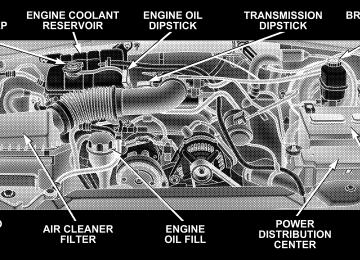
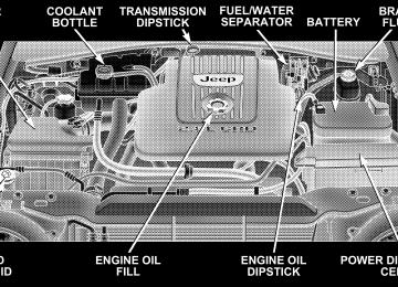
TO OPEN AND CLOSE THE HOOD To open the hood, two latches must be released. First pull the hood release lever inside your vehicle located under the left side of the instrument panel.
Then, reach under the hood and slide the safety latch to the right and lift the hood.
Hood Release Lever
Underhood Safety Latch
To prevent possible damage, do not slam the hood to close it. Lower the hood until it is open approximately 12
inches (30 cm) and then push hood closed. This shouldsecure both latches. Never drive your vehicle unless the hood is fully closed, with both latches engaged.
WARNING!
If the hood is not fully latched, it could fly up when the vehicle is moving and block your forward vision. Be sure all hood latches are latched fully before driving.
LIGHTS
Interior Lights The overhead lights will come on when a door is opened, and when the rotating ring on the multi-function control lever is in a position other than OFF. They may also be turned on by rotating the control for the dimmer switch on the multi-function control lever fully upward or by pressing the “Unlock” button on the keyfob.
UNDERSTANDING THE FEATURES OF YOUR VEHICLE 117
The overhead lights will automatically turn off in about 8
minutes if a door is left open or the dimmer control is left in the dome light position. Turn the ignition switch ON to restore the overhead light operation. Rear Cargo Light The rear cargo light includes an independent “On/Off” switch, which when “off” will not allow the illumination of any interior lighting when the rear swing gate or flipper glass is opened. All other methods of turning the interior lighting on/off will function normally regardless of the rear cargo light switch position. Dimmer Control With the park lights or headlights on, rotating the control for the dimmer switch on the multi-function control lever upward will increase the brightness of the instrument panel lights. Rotating the control completely upward turns on the dome light.118 UNDERSTANDING THE FEATURES OF YOUR VEHICLE
Daytime Brightness Feature Certain components (odometer, radio, etc.) can be illumi- nated at full brightness during the daytime. This can be helpful when driving with your headlights on during the daytime such as in a parade or a funeral procession. To activate this feature, rotate the multi-function control lever one detent lower than the dome light. Front Map/Reading Lights
These lights are mounted in the overhead console. Each light can be turned on by pressing the recessed area of the lens. To turn these lights off, press the recessed area of the lens a second time.
Multi-Function Control Lever The multi-function control lever controls the operation of the park lights, headlights, headlight beam selection, passing light, fog lights, instrument panel light dimming, and turn signals.
Multi-Function Control Lever
Parking Lights, Instrument Panel Lights, and Headlights Turn the end cap of the multi-function control lever to the first detent for parking lights and instrument panel lights. Turn to the second detent for headlight operation. To change the brightness of the instrument panel lights, rotate the center portion of the multi-function control lever up or down. High Beam/Low Beam Select Switch Pull the multi-function control lever towards you to switch the headlights to HIGH beam. Pull the multi- function control lever a second time to switch the head- lights to LOW beam. The “High Beam Indicator Light” will illuminate when the high beams are on.
UNDERSTANDING THE FEATURES OF YOUR VEHICLE 119
Passing Light You can signal another vehicle with your headlights by lightly pulling the multi-function control lever toward the steering wheel. This will cause the headlights to turn on at high beam and remain on until the lever is released. The “High Beam Indicator Light” will illuminate when the high beams are on. Turn Signals Move the multi-function control lever up or down and the arrows on each side of the instrument cluster flash to show proper operation of the front and rear turn signal lights. You can signal a lane change by moving the lever partially up or down without moving beyond the detent. If either light flashes at a very fast rate, check for a defective outside light bulb. If an indicator fails to light when the lever is moved, it would suggest that the fuse or indicator is defective.
120 UNDERSTANDING THE FEATURES OF YOUR VEHICLE
NOTE: A tone will chime if the turn signals are left on for more than 2 miles (3.2 km). Lights-On Reminder A chime will sound if the driver’s door is left open, and the headlights or parking lights are left on. Battery Saver Feature — Exterior Lights If the park lights, headlights, fog lights, or high beams are left on when the ignition switch is in the OFF position, the battery saver feature will automatically turn off the exterior lights after eight minutes. Normal operation will resume when the ignition is turned ON or when the switch is turned to another position.
Fog Lights — If Equipped
The front fog light switch is in the multi-function control lever. To activate the front fog lights, turn on the park or low beam headlights and pull out the end of the lever. The “Fog Light Indicator Light” will illuminate when the fog lights are on. NOTE: The fog lights will only operate with the park lights or the headlights on low beam. Selecting high beam headlights will turn off the fog lights. Daytime Running Lights — If Equipped The headlights come on at a low intensity level after the engine has started. They will turn off when the vehicle is turned off, when the headlights are switched on, or when the parking brake is set.
Light Bar — If Equipped
1. Remove lamp covers by pressing the thumb tab up- wards, and pulling the cover off.
UNDERSTANDING THE FEATURES OF YOUR VEHICLE 121
CAUTION!
The auxiliary lights mounted on the off road light bar should be illuminated during ⴖOFF-ROAD USE ONLY.ⴖ Having them illuminated on public streets, highways, roads, etc. may be illegal in your state. Your state may also require auxiliary lights be cov- ered when operating your vehicle on the public streets, highways, roads, etc. Further, illuminating these lights with the supplied covers installed could cause permanent damage to the light bar. Before using these auxiliary lights, contact your State Au- thorities for proper operation and use of these lights.
Light Bar
122 UNDERSTANDING THE FEATURES OF YOUR VEHICLE
2. With the ignition in the ON position, press the button to turn on the light bar (located on the instrument panel to the left of the steering column). Press the button again to turn off the light bar.
An indicator light in the instrument cluster will illumi- nate when the light bar has been activated. To reinstall lamp covers, insert the tab under the top center lip of the lamp housing. Rotate the cover until snap fit is aligned with notch in the bottom center of the housing. Push cover until it is securely snapped (flush) in the housing.
Light Bar Switch
UNDERSTANDING THE FEATURES OF YOUR VEHICLE 123
WINDSHIELD WIPERS AND WASHERS The wipers and washers are operated by a switch on the control lever. This control lever is located on the right side of the steering column. For front wiper operation, turn the control lever end cap upward to select the desired wiper speed.
Windshield Wiper/Washer Switch
124 UNDERSTANDING THE FEATURES OF YOUR VEHICLE
Windshield Washers To use the washer, pull the lever toward you and hold while spray is desired. If the lever is pulled while in the delay range, the wiper will operate for two wipe cycles after the lever is released, and then resume the intermit- tent interval previously selected. If vehicle is equipped with the optional Elec- NOTE: tronic Vehicle Information Center (EVIC) in the overhead console, all warnings including “door”, “GATE”, “GLASS”, and “LOWASH” will only be displayed in the EVIC display (not in the instrument cluster). For addi- tional information, refer to “Overhead Console — If Equipped” in Section 3. The vacuum fluorescent (VF) display located in the odometer area displays the word “LOWASH” when the washer solvent needs to be refilled. If the vehicle is not moving, when a low washer fluid condition is detected, the VF display will show the word “LOWASH” and then
show the odometer/trip odometer mileage (each for 2
seconds). The display will continue to cycle. If any other active warnings including “door”, “GATE”, or “GLASS” are present, they will be shown in the VF display and will continue to cycle. If the vehicle starts moving, two single chimes will occur (one chime for each complete display cycle). After this, the display will continue to sequence. After fifteen “LOWASH” se- quences, the VF display will no longer provide this warning. If the trip/reset button is pressed while the VF warnings are being displayed, the VF display will revert back to only displaying the odometer/trip odometer mileage. Once the warning is removed from the display, it will not return for the duration of the ignition cycle. If the lever is pulled while in the OFF position, the wipers will operate for several wipe cycles, then turn off.Mist Feature Push down on the wiper lever to activate a single wipe to clear off road mist or spray from a passing vehicle. As long as the lever is held down, the wipers will continue to operate.
CAUTION!
In cold weather, always turn off the wiper switch and allow the wipers to return to the park position before turning off the engine. If the wiper switch is left on and the wipers freeze to the windshield, damage to the wiper motor may occur when the vehicle is restarted.
UNDERSTANDING THE FEATURES OF YOUR VEHICLE 125
Windshield Wiper Operation Turn the control lever end cap upward to the middle mark (sixth detent) for Low speed wiper operation, or to the upper mark (seventh detent) for High speed opera- tion. Intermittent Wiper System
Use the intermittent wiper when weather conditions make a single wiping cycle, with a variable pause be- tween cycles, desirable. Move the control lever to any of the first five wiper switch positions by turning the end cap of the control lever. The delay can be regulated from a maximum of approximately 18 seconds between cycles, to a cycle every second.
126 UNDERSTANDING THE FEATURES OF YOUR VEHICLE
TILT STEERING COLUMN To tilt the column, push down on the lever below the turn signal control and move the wheel up or down, as desired. Pull the lever back towards you and firmly push the lever until it is above the lower surface of the shroud to lock the column in place.
Tilt Steering Column
WARNING!
Tilting the steering column while the vehicle is moving is dangerous. Without a stable steering col- umn, you could lose control of the vehicle and have an accident. Adjust the column only while the ve- hicle is stopped. Be sure it is locked before driving.
ELECTRONIC SPEED CONTROL When engaged, this device takes over accelerator opera- tions beginning at speeds of approximately 30 mph (48
km/h). The controls are mounted on the steering wheel and consist of ON·OFF, SET, RES·ACCEL, CANCEL, and DECEL controls.UNDERSTANDING THE FEATURES OF YOUR VEHICLE 127
To Activate Press and release the ON·OFF button to turn the system on. To turn the system off, press the ON·OFF button again. The system should be turned off when not in use. The CRUISE indicator light in the instrument cluster illuminates when the system is on.
128 UNDERSTANDING THE FEATURES OF YOUR VEHICLE
To Set At A Desired Speed When the vehicle has reached the desired speed, press and release the SET button. Release the accelerator and the vehicle will operate at the selected speed. To Deactivate
A soft tap on the brake pedal, normal braking, or pressing the CANCEL button will deactivate the Speed Control without erasing the memory. Pressing the ON·OFF but- ton or turning off the ignition erases the memory. To Resume Speed To resume a previously set speed, press and release the RES·ACCEL button. Resume can be used at any speed beginning at approximately 30 mph (48 km/h).
To Vary The Speed Setting When the Speed Control is on and set, speed can be increased by pressing and holding the RES·ACCEL but- ton. When the button is released, a new set speed will be established. Tapping the RES·ACCEL button once will result in a 2
mph (3 km/h) speed increase. Each time the button is tapped, speed increases, so tapping the button three times will increase speed by 6 mph (9 km/h), etc. To decrease speed while speed control is on and set, press and hold the DECEL button. Release the button when the desired speed is reached, and the new speed will be set. Tapping the DECEL button once will result in a 1 mph (2
km/h) speed decrease. Each time the button is tapped, speed decreases.To Accelerate for Passing Depress the accelerator as you would normally. When the pedal is released, the vehicle will return to the set speed. NOTE: When driving uphill, at elevations above 2,000
ft. (610 meters), or when the vehicle is heavily loaded (especially when towing) the vehicle may slow below the SET speed. (If the vehicle speed drops below 35 mph (56
km/h), the Speed Control will automatically disengage). If this happens, you can push down on the accelerator pedal to maintain the desired speed. A full throttle (high RPM) acceleration, while the system is engaged, will cause the system to disengage. Vehicles may exhibit several 4-3 downshifts under the above conditions. To reduce the frequency of the down- shifts and to improve vehicle performance, it is advisable to lock out overdrive. Press the O/D OFF button on the right side of the shift lever.UNDERSTANDING THE FEATURES OF YOUR VEHICLE 129
WARNING!
Leaving the Speed Control on when not in use is dangerous. You could accidentally set the system or cause it to go faster than you want. You could lose control and have an accident. Always turn the system off when you are not using it.
OVERHEAD CONSOLE — IF EQUIPPED The overhead console contains dome/reading lights, an optional universal garage door opener (HomeLink威), an optional sunroof switch, and an Electronic Vehicle Infor- mation Center (EVIC) that consists of the following: • Compass/temperature display • Trip information displays • Vehicle information warning message displays • Customer programmable features
130 UNDERSTANDING THE FEATURES OF YOUR VEHICLE
Pressing the MENU button will change the displayed programming features. Pressing the STEP button will select the available choices. Pressing the C/T (Compass/ Temperature) button will return the display to the normal compass/temperature display. NOTE: Temperature accuracy can be effected from heat soak. For best accuracy, the vehicle should be driven at a speed greater than 20 mph (32 km/h) for several min- utes. Dome/Reading Lights
Located in the overhead console are two dome/reading lights.
Dome Reading Lamps
The dome/reading lights illuminate when a door or the swing gate is opened or when the interior lights are turned on by rotating the dimmer control located on the multi-function lever.
The reading lights are activated by pressing on the recessed area of the corresponding lens. NOTE: The dome/reading lights will remain on until the switch is pressed a second time, so be sure they have been turned off before leaving the vehicle. Electronic Vehicle Information Center The electronic vehicle information center (EVIC), when the appropriate conditions exist, displays the following messages and symbols. Each message is accompanied by a series of beeps: • DRIVER DOOR OPEN • PASSENGER DOOR OPEN • N DOORS OPEN (N = 2, 3, 4) • RIGHT REAR DOOR OPEN • REARGATE OPEN
UNDERSTANDING THE FEATURES OF YOUR VEHICLE 131
• LEFT REAR DOOR OPEN • LIFTGLASS OPEN • TURN SIGNAL ON (with graphic) • PERFORM SERVICE • WASHER FLUID LOW • REMOTE KEY BATTERY LOW • NO J1850 BUS MSGS RECEIVED • LEFT FRONT LOW PRESSURE • RIGHT FRONT LOW PRESSURE • LEFT REAR LOW PRESSURE • RIGHT REAR LOW PRESSURE • SPARE LOW PRESSURE • CHECK TPM SYSTEM
132 UNDERSTANDING THE FEATURES OF YOUR VEHICLE
Customer Programmable Features Press the MENU button until one of the display choices following appears: Language? When in this display you may select one of five lan- guages for all display nomenclature, including the trip computer functions. Press the STEP button while in this display to select English, Francais, Deutsch, Italiana, or Espanol. As you continue the displayed information will be shown in the selected language. Display U.S. or Metric? Pressing the STEP button when in this display selects US or Metric. The overhead console and instrument panel displays will be in the selected units. Auto Door Locks? When this feature is selected, all doors and the swing gate will lock automatically when the speed of the
vehicle reaches 15 mph (25 km/h). Pressing the STEP button when in this display will select “Yes” or “No.” Auto Unlock On Exit? (Available Only When the AUTO DOOR LOCKS Feature is Turned On ) When this feature is selected all the vehicle’s doors will unlock when the driver’s door is opened if the vehicle is stopped and the transmission is in P (Park) or N (Neu- tral) position. Pressing the STEP button when in this display will select “Yes” or “No.” Remote Unlock Driver’s Door 1st? When this feature is selected only the driver’s door will unlock on the first press of the remote keyless entry unlock button and require a second press to unlock the remaining locked doors and swing gate. When REMOTE UNLOCK ALL DOORS is selected all of the doors and the swing gate will unlock at the first press of the remote keyless entry unlock button. Pressing the STEP button when in this display will select DRIVER’S DOOR 1ST or
ALL DOORS. This can also be programmed using the key fob, refer to “Remote Keyless Entry” earlier in this section. Train Remote? Pressing the STEP button when in this display will select “Yes” or “No.” NOTE: Any time you perform this procedure, it is necessary to retrain all currently trained key fobs. To Train Additional Key Fobs (using the EVIC module) 1. Press the MENU button until TRAIN REMOTE? NO is displayed. Press the STEP button to change to YES. Then, PRESS A VALID FOB KEY will be displayed. Press either the “Lock” or “Unlock” button on the current key fob. 2. The next display will say PRESS FOB 2 LOCK & UNLOCK. Press both key fob buttons simultaneously.
UNDERSTANDING THE FEATURES OF YOUR VEHICLE 133
3. The next display will say PRESS FOB 2 UNLOCK. Press the unlock button on the second key fob. 4. The next display will say FOB 2 TRAINED. At this point, the procedure can be exited by pressing the STEP, RESET, or C/T button. 5. Repeat step 2 — 4 to train additional key fobs. A total of four key fobs can be programmed. Can also be programmed using the key fob, refer to “Remote Keyless Entry” earlier in this section. Sound Horn On Lock? When this feature is selected, a short horn sound will occur when the remote keyless entry “Lock” button is pressed. This feature may be selected with or without the flash lights on lock/unlock feature. Pressing the STEP button when in this display will select “Yes” or “No.” Can also be programmed using the key fob, refer to “Remote Keyless Entry” earlier in this section.
134 UNDERSTANDING THE FEATURES OF YOUR VEHICLE
Flash Lights With Locks? When this feature is selected, the front and rear turn signals will flash when the doors are locked or unlocked using the remote keyless entry transmitter. This feature may be selected with or without the sound horn on lock feature selected. Pressing the STEP button when in this display will select “Yes” or “No.” Can also be pro- grammed using the key fob, refer to “Remote Keyless Entry” earlier in this section. Headlamp Delay When this feature is selected the driver can choose, when exiting the vehicle, to have the headlamps remain on for 30, 60, or 90 seconds, or not remain on. Pressing the STEP button when in this display will select 30, 60, 90, or OFF. Service Interval When this feature is selected a service interval between 2,000 miles (3 200 km) and 6,000 miles (10 000 km) in 500
mile (800 km) increments may be selected. Pressing theSTEP button when in this display will select distances between 2,000 miles (3 200 km) and 6,000 miles (10 000
km) in 500 mile (800 km) increments. Reset Service Distance (Displays Only if Service Interval was Changed) When this feature is selected the current accumulated service distance can be reset to the newly selected service interval. Pressing the STEP button when in this display will select “Yes” or “No.” Low Fuel Chime? When this feature is selected a chime will sound when the “Low Fuel Indicator Light” is displayed in the instrument panel cluster. Pressing the STEP button when in this display will select “Yes” or “No.”Mini-Trip Computer This feature, located in the overhead console, displays information on outside temperature, compass direction, and trip information. Reset Button Use this button to reset the Average Economy, Trip Miles, and Time Elapsed displays to zero. This will occur only if a resettable function is currently being displayed (Aver- age Economy, Trip Miles, and Time Elapsed). A single chime will sound to indicate that a reset has occurred. Global Reset If the RESET button is pressed twice within 3 seconds while in any of the three resettable displays, the RESET button will reset all three displays. A chime (two beeps) will sound to indicate that a reset has occurred.
UNDERSTANDING THE FEATURES OF YOUR VEHICLE 135
Menu Button Press the Menu button to scroll through the following screens: LANGUAGE, DISPLAY U.S. OR METRIC, AUTO DOOR LOCKS, AUTO UNLOCK ON EXIT, RE- MOTE UNLOCK DRIV DOOR 1ST, SOUND HORN WITH LOCK, FLASH LIGHTS WITH LOCKS, HEAD- LAMP DELAY, SERVICE INTV, LOW FUEL CHIME, and TRAIN REMOTE. C/T Button Press the C/T button to display the outside temperature and one of eight compass readings to indicate the direc- tion the vehicle is facing.
136 UNDERSTANDING THE FEATURES OF YOUR VEHICLE
WARNING!
Even if the display still reads a few degrees above 32°F (0°C), the road surface may be icy, particularly in woods or on bridges. Drive carefully under such conditions to prevent an accident and possible per- sonal injury or property damage.
Step Button Press the STEP button to cycle through all of the displays. The displays are: Average Miles/GAL, Miles To Empty, Trip Miles, Time Elapsed, Miles To Service, Tire PSI, and Blank Screen. Average Miles/GAL Shows the average fuel economy in miles per gallon (MPG), or liters per 100 km (L/100 km) since the last reset.
Miles To Empty Shows the estimated distance that can be traveled before the fuel gauge shows E (Empty). The distance is calcu- lated by multiplying the amount of fuel remaining by the projected fuel economy. The distance predicted will change every few seconds to a higher or lower number as these factors change. This display cannot be reset. Trip Miles Shows the distance traveled since the last reset. Time Elapsed Shows the accumulated ignition ON time since the last reset. Miles To Service Shows the amount of miles remaining until service is required (owner selected).
Tire PSI Shows the pressure and location of each tire, except for the spare tire. The tire location will blink when under pressure. Blank Screen Shows a blank screen. Pressing the C/T button returns to the Compass and Temperature display. Pressing the STEP button returns you to the Average Miles per Gallon display. Automatic Compass Calibration This compass is self-calibrating which eliminates the need to manually set the compass. When the vehicle is new, the compass may appear erratic and the CAL symbol will be displayed. After completing three 360 degree turns in an area free from large metal or metallic objects, the CAL symbol will turn off and the compass will function normally.
UNDERSTANDING THE FEATURES OF YOUR VEHICLE 137
Manual Compass Calibration If the compass appears erratic and the CAL symbol does not appear, you must manually put the compass into the “Calibration” mode. To Put Into a Calibration Mode Turn on the ignition and set the display to “Compass/ Temperature.” Press and hold the RESET button (more than 10 seconds) to change the display between VARI- ANCE (compass variance) and CAL (compass calibra- tion) modes. When the CAL symbol is displayed com- plete three 360 degree turns in an area free from large metal objects or power lines. The CAL symbol will turn off and the compass will function normally.
138 UNDERSTANDING THE FEATURES OF YOUR VEHICLE
Compass Variance is the difference between magnetic north and geographic north. In some areas of the country, the difference between magnetic and geographic north is great enough to cause the compass to give false readings. If this occurs, the compass variance must be set according to the Compass Variance Map. To set the variance: Turn the ignition ON and set the display to “Compass/Temperature.” Press and hold the RESET button five seconds (no more than 10 seconds). The last variance zone number will be displayed. Press the STEP button to select the new variance zone and press the RESET button to resume normal operation.
General Information This transmitter complies with FCC rules part 15 and with RSS-210 of Industry Canada. Operation is subject to the following two conditions: 1. This device may not cause harmful interference 2. This device must accept any interference that may be received, including interference that may cause undes- ired operation
CAUTION!
Changes or modifications not expressively approved by the party responsible for compliance could void the user’s authority to operate this equipment.
UNDERSTANDING THE FEATURES OF YOUR VEHICLE 139
GARAGE DOOR OPENER — IF EQUIPPED Equipped in vehicles that have the optional Electronic Vehicle Information Center (EVIC) The HomeLink威 Wireless Control System provides a convenient way to replace up to three hand-held radio- frequency (RF) transmitters used to activate devices such as gate operators, garage door openers, entry door locks, security systems, lighting. Additional HomeLink at: found www.homelink.com or by calling 1-800-355-3515.
even home can
information
be
140 UNDERSTANDING THE FEATURES OF YOUR VEHICLE
WARNING!
Before programming HomeLink to a garage door opener or gate operator, make sure that people and objects are out of the way of the device to prevent potential harm or damage. When programming a garage door opener, it is advised to park outside of the garage. Do not use HomeLink with any garage door opener that lacks safety stop and reverse fea- tures as required by U.S. federal safety standards (this includes any garage door opener model manu- factured before April 1, 1982). A garage door that cannot detect an object - signaling the door to stop and reverse - does not meet current U.S. federal safety standards. For more information, contact HomeLink at: www.homelink.com or by calling: 1-800-355-3515.
Retain the original transmitter of the RF device you are programming for use in other vehicles as well as for future HomeLink programming. It is also suggested that upon the sale of the vehicle, the programmed HomeLink buttons be erased for security purposes. To erase the programmed buttons, perform the procedure shown below under ⬙When Your Vehicle Is New⬙, or, for assis- tance, contact HomeLink at: www.homelink.com or by calling: 1-800-355-3515. When Your Vehicle Is New Prior to programming HomeLink for the first time the factory test codes must be erased. To erase HomeLink memory, press and hold the two outer HomeLink buttons (buttons one and three). The message CLEARING CHANNELS will appear on the HomeLink display. After approximately 20 seconds, the message CHANNELS CLEARED will appear on the EVIC display. Do not hold the buttons for longer than 30 seconds.
Programming HomeLink
It is recommended that a new battery be placed NOTE: in the hand-held transmitter of the device being pro- grammed to HomeLink for quicker training and accurate transmission of the radio frequency signal.
WARNING!
Vehicle exhaust contains carbon monoxide, a danger- ous gas. Do not run the vehicle’s engine while programming HomeLink. Exhaust gas can cause se- rious injury or death.
UNDERSTANDING THE FEATURES OF YOUR VEHICLE 141
WARNING!
Your motorized door or gate will open and close while you are programming HomeLink. Do not program HomeLink if people or pets are in the path of the door or gate. A moving door or gate can cause serious injury or death to people and pets or damage to objects.
1. Position the end of your hand-held transmitter 1-3
inches (5-14 cm) away from the lower left corner of the EVIC display while keeping the display in view. NOTE: Some gate operators and garage door openers may require you to replace the next step with procedures noted in the ⬙Gate Operator/Canadian Programming⬙ section.142 UNDERSTANDING THE FEATURES OF YOUR VEHICLE
2. Simultaneously press and hold both the desired HomeLink button and the hand-held transmitter button. After a short time, the message TRAINING will show on HomeLink display. Do not release the buttons until the next step has been completed.
HomeLink Buttons
3. When the message TRAINED appears on the HomeLink display, release both the HomeLink and hand- held transmitter buttons. If the HomeLink display does not change to NOTE: TRAINED, contact HomeLink at www.homelink.com or call 1-800-355-3515 for assistance. 4. Press and hold the just-trained HomeLink button. TRANSMIT should appear on the display. If your device activates when the HomeLink button is depressed and released, programming is complete. NOTE: To program the remaining two HomeLink but- tons, simply repeat the ⬙Programming HomeLink⬙ pro- cess.
If the message TRANSMIT appears on the HomeLink display but your device does not activate, the device may be equipped with a ⬙rolling code⬙ system. Continue with steps five through seven below to complete the program- ming of a rolling code equipped device (most commonly a garage door opener). 5. At the garage door opener receiver (motor-head unit) in the garage, locate the ⬙learn⬙ or ⬙smart⬙ button. This can usually be found where the hanging antenna wire is attached to the motor-head unit. 6. Firmly press and release the ⬙learn⬙ or ⬙smart⬙ button. (The name and color of the button may vary by manu- facturer.) NOTE: There are 30 seconds in which to initiate the next step.
UNDERSTANDING THE FEATURES OF YOUR VEHICLE 143
7. Return to the vehicle and firmly press, hold for two seconds and release the programmed HomeLink button. Repeat the ⬙press/hold/release⬙ sequence a second time, and, depending on the brand of the garage door opener (or other rolling code equipped device), repeat this sequence a third time to complete the programming process. HomeLink should now activate your equipped device. NOTE: To program the remaining two HomeLink but- tons, simply repeat the ⬙Programming Homelink⬙ pro- cess.
rolling code
144 UNDERSTANDING THE FEATURES OF YOUR VEHICLE
the hand-held transmitter
If, after programming the HomeLink Wireless Control System, and/or other HomeLink units in other vehicles fail to activate the rolling code equipped device, you may need to clear (or ⴖeraseⴖ) the device’s receiver memory. Refer to your garage door opener’s Owner’s Manual for the proce- dure or contact HomeLink at 1-800-355-3515 or on the Internet at www.homelink.com. After clearing the re- ceiver, you must reprogram the original hand-held transmitter(s) to the receiver using the procedure in the garage door opener’s Owner’s Manual. Finally, repro- gram the hand-held transmitter(s) to HomeLink using the steps under ⴖProgramming HomeLinkⴖ.
Gate Operator/Canadian Programming Canadian radio-frequency laws require transmitter sig- nals to ⬙time-out⬙ (or quit) after several seconds of transmission - which may not be long enough for HomeLink to pick up the signal during programming. Similar to this Canadian law, some U.S. gate operators are designed to ⬙time-out⬙ in the same manner. If you live in Canada or you are having difficulties programming a gate operator by using the ⬙Program- ming HomeLink⬙ procedures (regardless of where you live), replace step two with the following: If programming a garage door opener or gate NOTE: operator, it is advised to unplug the device during the ⬙cycling⬙ process to prevent possible overheating.
Press and hold the HomeLink button while you press and release - every two seconds (ⴖcycleⴖ) your hand-held transmitter button until the radio signal has success- fully been accepted by HomeLink. (The message TRAINED will appear on the HomeLink display.) Proceed with the remaining steps under ⬙Programming HomeLink⬙ to complete. Using HomeLink To operate, simply press and release the programmed HomeLink button. Activation will now occur for the trained device (i.e. garage door opener, gate operator,
UNDERSTANDING THE FEATURES OF YOUR VEHICLE 145
security system, entry door lock, home/office lighting, etc.). For convenience, the hand-held transmitter of the device may also be used at any time. In the event that there are still programming difficulties or questions, contact HomeLink at: www.homelink.com or 1-800-355-3515.
POWER SUNROOF — IF EQUIPPED The sunroof control is located on the headliner between the sun visors.
146 UNDERSTANDING THE FEATURES OF YOUR VEHICLE
Press and hold the switch rearward to fully open the sunroof. The sunroof can be stopped at any position between closed and full open. Momentarily pressing the switch rearward will activate the Express Open Feature, causing the sunroof to open automatically.
Power Sunroof Switch
Power Sunroof Switch
Press and hold the “V” button in the center of the sunroof switch to open the vent. The sunroof can be stopped at any position between closed and full vent. To close the sunroof from the vent position, press and hold the switch forward. Releasing the switch will stop the movement of
the sunroof and the sunroof will remain in the partial vent position until the switch is pushed forward again. Express Open Feature During the Express Open operation, any movement of the switch will stop the sunroof and it will remain in a partial open position. Again, momentarily pressing the switch rearward will activate the Express Open Feature. To close the sunroof, hold the switch in the forward position. Again, any release of the switch will stop the movement and the sunroof will remain in a partial open condition until the switch is pushed forward again. The sunroof is not completely closed until the rear of the sunroof glass moves upward at the end of it’s travel. The sunshade can be opened manually. It will also open as the sunroof opens. The sunshade cannot be closed if the sunroof is open.
UNDERSTANDING THE FEATURES OF YOUR VEHICLE 147
WARNING!
• In an accident, there is a greater risk of being thrown from a vehicle with an open sunroof. You could also be seriously injured or killed. Always fasten your seat belt properly and make sure all passengers are properly secured too. • Do not allow small children to operate the sun- roof. Never allow fingers or other body parts, or any object to project through the sunroof opening. Injury may result.
Sunroof Maintenance Use only a non-abrasive cleaner and a soft cloth to clean the glass panel.
148 UNDERSTANDING THE FEATURES OF YOUR VEHICLE
POWER OUTLET To the right of the convenience tray (lower center of instrument panel) is an outlet for electrically powered accessories. Pull lightly on the top of the plastic cover to open the outlet.
There is a rear power outlet located in the right rear cargo area above the storage cargo net/CD changer (if equipped).
Front Power Outlet
Rear Power Outlet
The rear power outlet is a direct feed from the battery so it receives power whether the ignition is in the ON or OFF position. All accessories connected to this outlet should be re- moved or turned off when the vehicle is not in use.
UNDERSTANDING THE FEATURES OF YOUR VEHICLE 149
CAUTION!
Electrical Outlet Use With Engine Off • Many accessories that can be plugged in draw power from the vehicle’s battery, even when not in use (i.e., cellular phones, etc.). Eventually, if plugged in long enough, the vehicle’s battery will discharge sufficiently to degrade battery life and/or prevent engine starting. • Accessories that draw higher power (i.e., coolers, vacuum cleaners, lights, etc.) will degrade the battery even more quickly. Only use these inter- mittently and with greater caution. • After the use of high power draw accessories, or long periods of the vehicle not being started (with accessories still plugged in), the vehicle must be driven a sufficient length of time to allow the alternator to recharge the vehicle’s battery.
150 UNDERSTANDING THE FEATURES OF YOUR VEHICLE
CUP HOLDERS In the center console there are two cup holders for the front seat passengers.
Smoker’s Package — If Equipped With the optional Smoker’s package, a removable ash tray is inserted into the front cup holder location. The rear passengers have access to a cup holder on each rear door trim panel.
Front Cup Holders
NOTE: The front cup holder insert is removable from the console, for cleaning.
Rear Cup Holders
CARGO AREA FEATURES
Cargo Light The cargo area light is activated by opening the swing gate, opening any door, or by rotating the dimmer control on the multi-function control lever to the extreme top position. If all doors are closed and only the swing gate is open, pushing on the cargo light lens surface will turn off all interior lights. Push on the lens surface a second time to restore the interior lights to normal operation. Retractable Cargo Area Cover — If Equipped To cover the cargo area: 1. Grasp the center portion of the cover flap. Pull it over the cargo area. 2. Insert the pins on the ends of the cover into the slots in the pillar trim cover.
UNDERSTANDING THE FEATURES OF YOUR VEHICLE 151
3. The swing gate may be opened or closed with the cargo cover in place.
Rear Cargo Cover
152 UNDERSTANDING THE FEATURES OF YOUR VEHICLE
WARNING!
In an accident a cargo cover loose in the vehicle could cause injury. It could fly around in a sudden stop and strike someone in the vehicle. Do not store the cargo cover on the cargo floor or in the passenger compart- ment. Remove the cover from the vehicle when taken from its mounting. Do not store in the vehicle.
Cargo Tie-Down Hooks The tie-downs located on cargo area floor should be used to safely secure loads when vehicle is moving.
Cargo Tie-Down Hooks
WARNING!
• Cargo tie-down hooks are not safe anchors for a child seat tether strap. In a sudden stop or colli- sion a hook could pull loose and allow the child seat to come loose. A child could be badly injured. Use only the anchors provided for child seat tethers. • The weight and position of cargo and passengers can change the vehicle center of gravity and vehicle handling. To avoid loss of control result- ing in personal injury, follow these guidelines for loading your vehicle:
• Always place cargo evenly on the cargo floor. Put heavier objects as low and as far forward as possible.
UNDERSTANDING THE FEATURES OF YOUR VEHICLE 153
• Place as much cargo as possible in front of the rear axle. Too much weight or improperly placed weight over or behind the rear axle can cause the rear of the vehicle to sway. • Do not pile luggage or cargo higher than the top of the seatback. This could impair visibility or become a dangerous projectile in a sudden stop or collision.
WARNING!
To help protect against personal injury, passengers should not be seated in the rear cargo area. The rear cargo space is intended for load carrying purposes only, not for passengers, who should sit in seats and use seat belts.
154 UNDERSTANDING THE FEATURES OF YOUR VEHICLE
Cargo Organizer — If Equipped This vehicle may be equipped with a cargo organizer that mounts on the floor behind the rear seat. Items may be placed on the flat surface or stored in the three storage compartments.
WARNING!
1. To raise the cargo organizer pull up on the handle and pull towards the rear of the vehicle.
positions.
• To avoid tipping, lock the shelf securely in all • Do not drive this vehicle with the liftgate open, or • Failure to follow these warnings could result in
use the shelf as a seat.
serious or fatal injury.
Cargo Organizer
2. Place the rear corners of the cargo organizer into the supports located on the rear trim panel. Press down on the back of the cargo organizer to lock it into place.
Cargo Organizer Mounting
UNDERSTANDING THE FEATURES OF YOUR VEHICLE 155
WARNING!
Do not load objects over 30 lbs (13.5 kg) in the upper position. Failure to follow this warning could cause the cargo organizer to collapse resulting in personal injury.
CAUTION!
Do not load objects over 100 lbs (45 kg) in the lower position. Failure to follow this could cause damage to the cargo organizer.
156 UNDERSTANDING THE FEATURES OF YOUR VEHICLE
To Open Storage Compartments 1. Pull up on the center opening of the cargo organizer.
Using Cargo Organizer
2. Lift up on the storage compartment dividers and lock into place.
Cargo Organizer Removal Loosen screw, then lift lever from each mount located on the floor of the rear cargo area, and remove the cargo organizer from the vehicle.
REAR WINDOW FEATURES
Rear Window Wiper/Washer A rotary ring switch on the control lever, located on the right side of the steering column, controls operation of the rear wiper/washer function. Rotating the center of the switch up to the DEL (Delay) position or the ON position will activate the wiper. Rotating the switch ring beyond the ON or OFF position will activate the rear washer. The wash pump will continue to operate as long as the lever or ring is engaged. Upon release, the wipers will cycle three times before returning to the set position.
If the rear wiper is operating when the ignition is turned OFF, the wiper will automatically return to the “Park” position. When the vehicle is restarted, the wiper will resume function at whichever position the switch is set at. If the swing gate flip-up window is open or the swing gate is open, connection to the rear window wiper is interrupted preventing activation of the rear wiper blade. When the swing gate flip-up window or the swing gate is closed, the rear wiper switch or the ignition switch needs to be turned OFF, and then to ON to restart the rear wiper.
UNDERSTANDING THE FEATURES OF YOUR VEHICLE 157
NOTE: The rear swing gate will lock while the rear wiper is operating. The gate will stay locked until the wiper is turned off and the gate is unlocked (by key, lock switch, or key fob).
Adding Washer Fluid The fluid reservoir for the windshield washers and the rear window washer is shared. It is located in the front of the engine compartment on the passenger side and should be checked for fluid level at regular intervals. Fill the reservoir with windshield washer solvent (not radia- tor antifreeze) and operate the system for a few seconds to flush out the residual water.
158 UNDERSTANDING THE FEATURES OF YOUR VEHICLE
Rear Window Defroster
On the top of the climate control panel is a push button for rear window defrosting. An amber indicator in the push button will light when the defroster is turned on. Push again to turn off the defroster prior to an automatic time-out.
The defroster will automatically turn off after about ten minutes. For about five more minutes of operation, push the button again. To prevent excessive battery drain, use the defroster only when the engine is operating. The push button also activates the heated exterior mirrors, if so equipped.
CAUTION!
Use care when washing the inside of the rear win- dow to prevent damage to heating elements. Use a soft cloth and a mild washing solution, wiping parallel to the heating elements. Also, keep all objects a safe distance from the window to prevent damaging the heating elements.
Rear Defroster Switch
ROOF LUGGAGE RACK External racks do not increase the total load carrying capacity of the vehicle. Be sure that the total occupant and luggage load inside the vehicle, plus the load on the luggage rack, do not exceed the rated vehicle capacity as shown on the label attached to the drivers door shut face.
UNDERSTANDING THE FEATURES OF YOUR VEHICLE 159
CAUTION!
• To avoid damage to the roof rack and vehicle, do not exceed the maximum roof rack load capacity of 150 lbs (68 kg) or 65 lbs (29.5 kg) on Renegade models. Always distribute heavy loads as evenly as possible and secure the load appropriately. • Long loads which extend over the windshield, such as wood panels or surfboards, should be secured to both the front and rear of the vehicle. • Place a blanket or other protection between the • Travel at reduced speeds and turn corners carefully when carrying large or heavy loads on the roof rack. Wind forces, due to natural causes or nearby truck traffic, can add sudden upward loads. This is espe- cially true on large flat loads and may result in damage to the cargo or your vehicle.
surface of the roof and the load.
160 UNDERSTANDING THE FEATURES OF YOUR VEHICLE
WARNING!
Cargo must be securely tied before driving your vehicle. Improperly secured loads can fly off the vehicle, particularly at high speeds, resulting in personal injury or property damage. Follow the roof rack “Cautions” when carrying cargo on your roof rack.
UNDERSTANDING YOUR INSTRUMENT PANEL
CONTENTS
䡵 Instrument Panel And Interior Controls . . . . . . . 165
䡵 Instrument Cluster . . . . . . . . . . . . . . . . . . . . . . 166
▫ 2.4L/3.7L Engines . . . . . . . . . . . . . . . . . . . . . 166
▫ 2.8L Diesel Engines . . . . . . . . . . . . . . . . . . . . 167
䡵 Instrument Cluster Description . . . . . . . . . . . . . 168
䡵 Electronic Digital Clock . . . . . . . . . . . . . . . . . . 176
▫ Clock Setting Procedure . . . . . . . . . . . . . . . . . 176
䡵 Radio General Information . . . . . . . . . . . . . . . . 177
▫ Radio Broadcast Signals . . . . . . . . . . . . . . . . . 177▫ Two Types Of Signals . . . . . . . . . . . . . . . . . . 177
▫ Electrical Disturbances . . . . . . . . . . . . . . . . . . 177
▫ AM Reception . . . . . . . . . . . . . . . . . . . . . . . 177
▫ FM Reception . . . . . . . . . . . . . . . . . . . . . . . . 177䡵 Sales Code RAZ—AM/ FM Stereo Radio With
Cassette Tape Player, CD Player And CD Changer Controls . . . . . . . . . . . . . . . . . . . . . . . . . . . . . 178
▫ Operating Instructions — Radio . . . . . . . . . . . 178
▫ Power Switch, Volume Control . . . . . . . . . . . . 178
▫ Seek Button (Radio Mode) . . . . . . . . . . . . . . . 178162 UNDERSTANDING YOUR INSTRUMENT PANEL
▫ Tuning . . . . . . . . . . . . . . . . . . . . . . . . . . . . . 179
▫ Radio Data System (RDS) . . . . . . . . . . . . . . . 179
▫ PTY (Program Type) Button . . . . . . . . . . . . . . 179
▫ Balance . . . . . . . . . . . . . . . . . . . . . . . . . . . . 181
▫ Fade . . . . . . . . . . . . . . . . . . . . . . . . . . . . . . 181
▫ Tone Control . . . . . . . . . . . . . . . . . . . . . . . . 181
▫ AM/FM Selection . . . . . . . . . . . . . . . . . . . . . 181
▫ Scan Button . . . . . . . . . . . . . . . . . . . . . . . . . 181
▫ To Set The Radio Push-Button Memory . . . . . . 182
▫ To Change From Clock To Radio Mode . . . . . . 182
▫ Operating Instructions — Tape Player . . . . . . . 182
▫ Seek Button . . . . . . . . . . . . . . . . . . . . . . . . . 182
▫ Fast Forward (FF) . . . . . . . . . . . . . . . . . . . . . 183▫ Rewind (RW) . . . . . . . . . . . . . . . . . . . . . . . . 183
▫ Tape Eject . . . . . . . . . . . . . . . . . . . . . . . . . . . 183
▫ Scan Button . . . . . . . . . . . . . . . . . . . . . . . . . 183
▫ Changing Tape Direction . . . . . . . . . . . . . . . . 183
▫ Metal Tape Selection . . . . . . . . . . . . . . . . . . . 183
▫ Pinch Roller Release . . . . . . . . . . . . . . . . . . . 184
▫ Noise Reduction . . . . . . . . . . . . . . . . . . . . . . 184
▫ Operating Instructions — CD Player . . . . . . . . 184
▫ Inserting The Compact Disc . . . . . . . . . . . . . . 184
▫ Seek Button . . . . . . . . . . . . . . . . . . . . . . . . . 185
▫ EJT CD (Eject) Button . . . . . . . . . . . . . . . . . . 185
▫ FF/Tune/RW . . . . . . . . . . . . . . . . . . . . . . . . 186
▫ Program Button 4 (Random Play) . . . . . . . . . . 186▫ Mode . . . . . . . . . . . . . . . . . . . . . . . . . . . . . . 186
▫ Tape CD Button . . . . . . . . . . . . . . . . . . . . . . 186
▫ Time Button . . . . . . . . . . . . . . . . . . . . . . . . . 187
▫ Scan Button . . . . . . . . . . . . . . . . . . . . . . . . . 187
▫ CD Changer Control Capability —If Equipped . . . . . . . . . . . . . . . . . . . . . . . . . 187
䡵 Sales Code RBK—AM/ FM Stereo Radio With
CD Player And CD Changer Controls . . . . . . . . 189
▫ Radio Operation . . . . . . . . . . . . . . . . . . . . . . 189
▫ CD Player Operation . . . . . . . . . . . . . . . . . . . 191
▫ CD Changer Control Capability —If Equipped . . . . . . . . . . . . . . . . . . . . . . . . . 193
䡵 Sales Code RBQ—AM/FM Stereo Radio With
6 - Disc CD Changer
. . . . . . . . . . . . . . . . . . . . 195
UNDERSTANDING YOUR INSTRUMENT PANEL 163
▫ Radio Operation . . . . . . . . . . . . . . . . . . . . . . 195
▫ CD Player Operation . . . . . . . . . . . . . . . . . . . 198䡵 Sales Code RB1—AM/FM Stereo Radio With
DVD/GPS Navigation System . . . . . . . . . . . . . . 203
䡵 Satellite Radio — If Equipped . . . . . . . . . . . . . . 203
▫ System Activation . . . . . . . . . . . . . . . . . . . . . 204
▫ Electronic Serial Number/Sirius IdentificationNumber (ENS/SID) . . . . . . . . . . . . . . . . . . . . 204
▫ Selecting Satellite Mode In RBB, RAH And
RBK Radios . . . . . . . . . . . . . . . . . . . . . . . . . 205
▫ Selecting Satellite Mode In RBP, RBU, RAZ,
RB1 And RBQ Radios . . . . . . . . . . . . . . . . . . 205
▫ Selecting a Channel . . . . . . . . . . . . . . . . . . . . 206
▫ Storing And Selecting Pre-Set Channels . . . . . . 206164 UNDERSTANDING YOUR INSTRUMENT PANEL
▫ Using The PTY (Program Type) Button
(If Equipped)
. . . . . . . . . . . . . . . . . . . . . . . . 206
▫ PTY Button ⬙Scan⬙ . . . . . . . . . . . . . . . . . . . . . 206
▫ PTY Button ⬙Seek⬙ . . . . . . . . . . . . . . . . . . . . . 207
▫ Satellite Antenna . . . . . . . . . . . . . . . . . . . . . . 207
▫ Reception Quality . . . . . . . . . . . . . . . . . . . . . 207
䡵 Remote Sound System Controls — If Equipped . . 208
▫ Radio Operation . . . . . . . . . . . . . . . . . . . . . . 209
▫ Tape Player . . . . . . . . . . . . . . . . . . . . . . . . . 209
▫ CD Player — Single Disc In Radio . . . . . . . . . 209▫ CD Player — 6 Disc In Cargo Area . . . . . . . . . 209
䡵 Cassette Tape And Player Maintenance . . . . . . . 210
䡵 CD/DVD Disc Maintenance . . . . . . . . . . . . . . . 211
䡵 Radio Operation And Cellular Phones . . . . . . . . 211
䡵 Climate Controls . . . . . . . . . . . . . . . . . . . . . . . 212
▫ Blower Control . . . . . . . . . . . . . . . . . . . . . . . 212
▫ Temperature Control . . . . . . . . . . . . . . . . . . . 212
▫ Mode Selection . . . . . . . . . . . . . . . . . . . . . . . 212
▫ Operating Tips . . . . . . . . . . . . . . . . . . . . . . . 214INSTRUMENT PANEL AND INTERIOR CONTROLS
UNDERSTANDING YOUR INSTRUMENT PANEL 165
166 UNDERSTANDING YOUR INSTRUMENT PANEL
INSTRUMENT CLUSTER
2.4L/3.7L ENGINES
2.8L DIESEL ENGINES
UNDERSTANDING YOUR INSTRUMENT PANEL 167
168 UNDERSTANDING YOUR INSTRUMENT PANEL
INSTRUMENT CLUSTER DESCRIPTION
1. Tachometer Indicates the permissible engine revolutions-per-minute for each gear range. Before reaching the red area, ease up on the accelerator to prevent engine damage. 2. Turn Signal Indicator Light
The arrows will flash in unison with the exterior turn signals, when using the multi-function control lever. A chime will sound if the turn signals are left on continuously for 2 miles (3 km) until they are deacti- vated. 3. High Beam Indicator Light
This light shows that the headlights are on high beam. Pull the multi-function control lever to- wards the steering wheel to switch the headlights from high to low beam.
4. Speedometer Indicates vehicle speed. 5. Tire Pressure Monitor Warning Light — If Equipped This light will turn on when there is a low tire pressure condition. The light will also turn on if a problem exist with any tire sensor. The light will remain on until the tire pressure is prop-
erly set or the problem with the sensor is corrected. This light will turn on momentarily as a bulb check when the engine is started. When the “Tire Pressure Monitor Warning Light” is lit, one or more of your tires is significantly under-inflated. You should stop and check your tires as soon as possible, and inflate them to the proper pressure as indicated on the vehicle’s tire information placard. Driving on a significantly under-inflated tire causes the tire to over- heat and can lead to tire failure. Under-inflation also reduces fuel efficiency and tire tread life, and may affect
the vehicle’s handling and stopping ability. Each tire, including the spare, should be checked monthly when cold and set to the recommended inflation pressure as specified on the vehicle placard. (See page 268 for more information.) 6. 4LO Mode Indicator Light — If Equipped
This light alerts the driver that the vehicle is in the 4 LO four–wheel drive mode. The front and rear driveshafts are mechanically locked to- gether forcing the front and rear wheels to rotate at the same speed. (See page 236 for more infor- mation.) 7. Fog Light Indicator Light — If Equipped
This light shows when the front fog lights are on.
UNDERSTANDING YOUR INSTRUMENT PANEL 169
8. Malfunction Indicator Light
This light is part of an onboard diagnostic system called OBD II which monitors engine and auto- matic transmission control systems. This light will illuminate when the ignition is in the ON position