- 2008 Jeep Compass Owners Manuals
- Jeep Compass Owners Manuals
- 2011 Jeep Compass Owners Manuals
- Jeep Compass Owners Manuals
- 2007 Jeep Compass Owners Manuals
- Jeep Compass Owners Manuals
- 2013 Jeep Compass Owners Manuals
- Jeep Compass Owners Manuals
- 2009 Jeep Compass Owners Manuals
- Jeep Compass Owners Manuals
- 2012 Jeep Compass Owners Manuals
- Jeep Compass Owners Manuals
- 2010 Jeep Compass Owners Manuals
- Jeep Compass Owners Manuals
- Download PDF Manual
-
lower than expected, check the front of the A/C con- denser located in front of the radiator for an accumula- tion of dirt or insects. Clean with a gentle water spray from behind the radiator and through the condenser. Fabric front fascia protectors may reduce airflow to the condenser, reducing air conditioning performance.
Mode Control (Air Direction)
Rotate this control to choose from sev- eral patterns of air distribution. You can select either a primary mode as identified by the symbols on the con- trol, or a blend of two of these modes. The closer the setting is to a particular symbol, the more air distribution you
receive from that mode. Panel
Air is directed through the outlets in the instrument panel. These outlets can be adjusted to direct airflow. NOTE: The center instrument panel outlets can be aimed so that they are directed toward the rear seat passengers for maximum airflow to the rear. Bi-Level
Air is directed through the panel and floor outlets.
UNDERSTANDING YOUR INSTRUMENT PANEL 273
NOTE: For all settings, except full cold or full hot, there is a difference in temperature between the upper and lower outlets. The warmer air flows to the floor outlets. This feature gives improved comfort during sunny but cool conditions. FloorAir is directed through the floor outlets with a small amount flowing through the defrost and side
window demist outlets. Mix
Air is directed through the floor, defrost, and side window demist outlets. This setting works best in cold or snowy conditions that require extra heat to the windshield. This setting is good for maintaining comfort while reducing moisture on the windshield.
274 UNDERSTANDING YOUR INSTRUMENT PANEL Defrost
Air is directed through the windshield and side window demist outlets. Use this mode with maxi- mum blower and temperature settings for best wind- shield and side window defrosting. NOTE: • The air conditioning compressor operates in Mix, Defrost, or a blend of these modes, even if the Air Conditioning (A/C) button is not pressed. This dehu- midifies the air to help dry the windshield. To improve fuel economy, use these modes only when necessary. • For information on operating the Rear Defrost, refer to “Rear Window Features†in “Understanding The Fea- tures Of Your Vehicleâ€.
Recirculation Control
Pressing the Recirculation Control button will put the system in recirculation mode. This can be used when outside conditions such as smoke, odors, dust, or high humidity are pres- ent. Activating recirculation will cause the LED in the control button to illuminate. NOTE: • Continuous use of the Recirculation mode may make the inside air stuffy and window fogging may occur. Extended use of this mode is not recommended. • The use of the Recirculation mode in cold or damp weather will cause windows to fog on the inside, because of moisture buildup inside the vehicle. Select the outside air position for maximum defogging. • The A/C will engage automatically to prevent fogging when the recirculation button is pressed and the mode control is set to panel or panel / floor.
ing the mode control selection.
• The A/C can be deselected manually without disturb- • When the ignition switch is turned to the LOCK position, the recirculation feature will be cancelled.
Air Conditioning Control
Press this button to engage the Air Conditioning. A light will illuminate when the Air Conditioning system is engaged. Rotating the dial left into the blue area of the scale indicates cooler temperatures, while rotating right into the red area indicates warmer tem- peratures.
UNDERSTANDING YOUR INSTRUMENT PANEL 275
NOTE: The air conditioning compressor will not engage until the engine has been running for about 10 seconds. • MAX A/C For maximum cooling use the A/C and recirculation buttons at the same time. • ECONOMY MODE If economy mode is desired, press the A/C button to turn OFF the indicator light and the A/C compressor. Then, move the temperature control to the desired temperature.276 UNDERSTANDING YOUR INSTRUMENT PANEL Automatic Temperature Control (ATC) — If Equipped The Automatic Temperature Control system automati- cally maintains the climate in the cabin of the vehicle at the comfort levels desired by the driver and passenger.
Automatic Temperature Control
Automatic Operation Operation of the system is quite simple. 1. Turn the Mode Control knob (on the right) and the Blower Control knob (on the left) to AUTO. NOTE: The AUTO position performs best for front seat occupants only.
2. Dial in the temperature you would like the system to maintain by rotating the Temperature Control knob. Once the comfort level is selected, the sys- tem will maintain that level automati- cally using the heating system. Should the desired comfort level require air conditioning, the system will automatically make the adjustment.
You will experience the greatest efficiency by simply allowing the system to function automatically. Selecting the “O†(OFF) position on the blower control stops the system completely and closes the outside air intake. The recommended setting for maximum comfort for the average person is 72°F (22°C); however, this may vary. NOTE: • The temperature setting can be adjusted at anytime
without affecting automatic operation.
UNDERSTANDING YOUR INSTRUMENT PANEL 277
• Pressing the Air Conditioning Control button while in AUTO mode will cause the LED in the control button to flash three times and then turn off. This indicates that the system is in AUTO mode and requesting the air conditioning is not necessary. • If your air conditioning performance seems lower than expected, check the front of the A/C condenser located in front of the radiator for an accumulation of dirt or insects. Clean with a gentle water spray from behind the radiator and through the condenser. Fabric front fascia protectors may reduce airflow to the condenser, reducing air conditioning performance.
278 UNDERSTANDING YOUR INSTRUMENT PANEL Blower Control
For full automatic operation or for automatic blower operation, turn the knob to the AUTO position. In manual mode there are seven blower speeds that can be individual selected. In off position the blower will shut off.
Manual Operation This system offers a full complement of manual override features, which consist of Blower Preferred Automatic,
Mode Preferred Automatic, or Blower and Mode Pre- ferred Automatic. This means the operator can override the blower, the mode, or both. There is a manual blower range for times when the AUTO setting is not desired. The blower can be set to any fixed blower speed by rotating the Blower Control knob (on the left). NOTE: Please read the Automatic Temperature Control Operation Chart that follows for details.
UNDERSTANDING YOUR INSTRUMENT PANEL 279
280 UNDERSTANDING YOUR INSTRUMENT PANEL The operator can override the AUTO mode setting to change airflow distribution by rotating the Mode Control knob (on the right) to one of the following positions. • Panel
Air is directed through the outlets in the instrument panel. These outlets can be adjusted to direct airflow. NOTE: The center instrument panel outlets can be aimed so that they are directed toward the rear seat passengers for maximum airflow to the rear. • Bi-Level
Air is directed through the panel and floor outlets.
NOTE: For all settings, except full cold or full hot, there is a difference in temperature between the upper and lower outlets. The warmer air flows to the floor outlets. This feature gives improved comfort during sunny but cool conditions.
Air is directed through the floor outlets with a small amount flowing through the defrost and side
• Floor
window demist outlets. • Mix
Air is directed through the floor, defrost, and side window demist outlets. This setting works best in cold or snowy conditions that require extra heat to the windshield. This setting is good for maintaining comfort while reducing moisture on the windshield. • Defrost
Air is directed through the windshield and side window demist outlets. Use this mode with maxi- mum blower and temperature settings for best wind- shield and side window defrosting.
• Air Conditioner Control
Press this button to turn on the air conditioning during manual operation only. When the air conditioning is turned on, cool dehumidified air will flow through the outlets selected with the Mode control dial. Press this but- ton a second time to turn OFF the air conditioning. An LED in the button illuminates when manual compressor operation is selected. • Recirculation Control
The system will automatically control recircu- lation. However, pressing the Recirculation Control button will put the system in recircu- lation mode. This can be used when outside conditions such as smoke, odors, dust, or high humidity are present. Activating recirculation will cause the LED in the control button to illuminate.
UNDERSTANDING YOUR INSTRUMENT PANEL 281
NOTE: • When the ignition switch is turned to the LOCK position, the recirculation feature will be cancelled. • In cold weather, use of the Recirculation mode may lead to excessive window fogging. The Recirculation mode is not allowed in the floor, defrost, or defrost/ floor mode in order to improve window clearing. Recirculation will be disabled automatically if these modes are selected. • Extended use of recirculation may cause the windows to fog. If the interior of the windows begins to fog, press the Recirculation button to return to outside air. Some temp/humidity conditions will cause captured interior air to condense on windows and hamper visibility. For this reason, the system will not allow Recirculation to be selected while in floor, defrost, or defrost/floor mode. Attempting to use the recircula- tion while in these modes will cause the LED in the control button to blink and then turn off.
282 UNDERSTANDING YOUR INSTRUMENT PANEL
• Most of the time, when in Automatic Operation, you can temporarily put the system into Recirculation Mode by pressing the Recirculation button. However, under certain conditions, while in Automatic Mode, the system is blowing air out the defrost vents. When these conditions are present, and the Recirculation button is pressed, the indicator will flash and then turn off. This tells you that you are unable to go into Recirculation Mode at this time. If you would like the system to go into Recirculation Mode, you must first move the Mode knob to Panel, Panel/Floor and then press the Recirculation button. This feature reduces the possibility of window fogging.
Operating Tips
NOTE: Refer to the chart at the end of this section for suggested control settings for various weather condi- tions.
Summer Operation The engine cooling system in air-conditioned vehicles must be protected with a high-quality antifreeze coolant to provide proper corrosion protection and to protect against engine overheating. A solution of 50% ethylene glycol antifreeze coolant and 50% water is recommended. Refer to “Maintenance Procedures†in “Maintaining Your Vehicle†for proper coolant selection. Winter Operation Use of the air Recirculation Mode during winter months is not recommended because it may cause window fogging. Vacation Storage Anytime you store your vehicle, or keep it out of service (i.e., vacation) for two weeks or more, run the air conditioning system at idle for about five minutes in the fresh air and high blower settings. This will ensure adequate system lubrication to minimize the possibility of compressor damage when the system is started again.
Window Fogging Interior fogging on the windshield can be quickly re- moved by turning the mode selector to Defrost. The Defrost/Floor mode can be used to maintain a clear windshield and provide sufficient heating. If side win- dow fogging becomes a problem, increase blower speed. Vehicle windows tend to fog on the inside in mild but rainy or humid weather. NOTE: Recirculate without A/C should not be used for long periods as fogging may occur. Side Window Demisters A side window demister outlet is located at each end of the instrument panel. These non-adjustable outlets direct air toward the side windows when the system is in the FLOOR, MIX, or DEFROST mode. The air is directed at the area of the windows through which you view the outside mirrors.
UNDERSTANDING YOUR INSTRUMENT PANEL 283
Outside Air Intake Make sure the air intake, located directly in front of the windshield, is free of obstructions such as leaves. Leaves collected in the air intake may reduce airflow, and if they enter the plenum, they could plug the water drains. In winter months, make sure the air intake is clear of ice, slush, and snow. A/C Air Filter — If Equipped The A/C Filter prevents most dust and pollen from entering the cabin. The filter acts on air coming from outside the vehicle and recirculated air within the pas- senger compartment. Refer to “Maintenance Procedures†in “Maintaining Your Vehicle†for A/C Air Filter service information or see your authorized dealer for service. Refer to “Maintenance Schedules†for filter service intervals.
284 UNDERSTANDING YOUR INSTRUMENT PANEL Control Setting Suggestions for Various Weather Conditions
STARTING AND OPERATING
CONTENTS
䡵 Starting Procedures . . . . . . . . . . . . . . . . . . . . 289
▫ Manual Transmission – If Equipped . . . . . . . 289
▫ Automatic Transmission – If Equipped . . . . . 289
â–« Normal Starting . . . . . . . . . . . . . . . . . . . . . 290
▫ Extreme Cold Weather(Below –20°F Or ⫺29°C) . . . . . . . . . . . . . . . 290
â–« If Engine Fails To Start . . . . . . . . . . . . . . . . 291
â–« After Starting . . . . . . . . . . . . . . . . . . . . . . . 291
䡵 Engine Block Heater — If Equipped . . . . . . . . 291䡵 Manual Transmission — If Equipped . . . . . . . . 292
▫ Five–Speed Manual Transmission . . . . . . . . . 292
â–« Recommended Shift Speeds . . . . . . . . . . . . . 293
â–« Downshifting . . . . . . . . . . . . . . . . . . . . . . . 293
䡵 Automatic Transmission — If Equipped . . . . . . 294▫ Automatic Transmission Ignition Interlock
System . . . . . . . . . . . . . . . . . . . . . . . . . . . . 295
â–« Brake/Transmission Interlock System . . . . . . 295
â–« Gear Ranges . . . . . . . . . . . . . . . . . . . . . . . . 296286 STARTING AND OPERATING 䡵 AutoStickå¨ â€” If Equipped . . . . . . . . . . . . . . . 298
â–« Operation . . . . . . . . . . . . . . . . . . . . . . . . . 298
â–« General Information . . . . . . . . . . . . . . . . . . 299
䡵 Four-Wheel Drive Operation — If Equipped . . 300
䡵 On-Road Driving Tips . . . . . . . . . . . . . . . . . . 300
䡵 Power Steering . . . . . . . . . . . . . . . . . . . . . . . 301
â–« Power Steering Fluid Check . . . . . . . . . . . . . 302
䡵 Parking Brake . . . . . . . . . . . . . . . . . . . . . . . . 303
䡵 Brake System . . . . . . . . . . . . . . . . . . . . . . . . 305
â–« Anti-Lock Brake System (ABS) . . . . . . . . . . . 306
䡵 Electronic Brake Control System . . . . . . . . . . . 308
â–« Anti-Lock Brake System (ABS) . . . . . . . . . . . 309
â–« Traction Control System (TCS) . . . . . . . . . . . 309â–« Brake Assist System (BAS) . . . . . . . . . . . . . . 309
â–« Electronic Roll Mitigation (ERM) . . . . . . . . . 310
▫ Hill Descent Control (HDC) – If Equipped . . 311
▫ Hill Start Assist (HSA) – ManualTransmission Only . . . . . . . . . . . . . . . . . . . 312
. . . . . . . . . 314â–« Electronic Stability Control (ESC) â–« ESC Activation/Malfunction Indicator Light
And ESC Off Indicator Light
. . . . . . . . . . . . 317
䡵 Tire Safety Information . . . . . . . . . . . . . . . . . 318
â–« Tire Markings . . . . . . . . . . . . . . . . . . . . . . . 318
â–« Tire Identification Number (TIN) . . . . . . . . . 322
â–« Tire Terminology And Definitions . . . . . . . . . 323
▫ Tire Loading And Tire Pressure . . . . . . . . . . 324䡵 Tires — General Information . . . . . . . . . . . . . 328
â–« Tire Pressure . . . . . . . . . . . . . . . . . . . . . . . 328
â–« Tire Inflation Pressures . . . . . . . . . . . . . . . . 329
â–« Tire Pressures For High Speed Operation . . . 330
â–« Radial Ply Tires . . . . . . . . . . . . . . . . . . . . . 331
▫ Spare Tire Matching Original Equipped TireAnd Wheel – If Equipped . . . . . . . . . . . . . . 332
▫ Compact Spare Tire – If Equipped . . . . . . . . 332
▫ Full Size Spare – If Equipped . . . . . . . . . . . . 333
▫ Limited-Use Spare – If Equipped . . . . . . . . . 333
â–« Tire Spinning . . . . . . . . . . . . . . . . . . . . . . . 334
â–« Tread Wear Indicators . . . . . . . . . . . . . . . . . 335
â–« Life Of Tire . . . . . . . . . . . . . . . . . . . . . . . . 335STARTING AND OPERATING 287
â–« Replacement Tires . . . . . . . . . . . . . . . . . . . . 336
䡵 Tire Chains . . . . . . . . . . . . . . . . . . . . . . . . . . 337
䡵 Snow Tires . . . . . . . . . . . . . . . . . . . . . . . . . . 337
䡵 Tire Rotation Recommendations . . . . . . . . . . . 338
䡵 Tire Pressure Monitoring System (TPMS) . . . . . 339
â–« Base System . . . . . . . . . . . . . . . . . . . . . . . . 341
▫ Premium System – If Equipped . . . . . . . . . . 344
â–« General Information . . . . . . . . . . . . . . . . . . 348
䡵 Fuel Requirements . . . . . . . . . . . . . . . . . . . . . 349
â–« 2.0L And 2.4L Engine . . . . . . . . . . . . . . . . . 349
â–« Reformulated Gasoline . . . . . . . . . . . . . . . . 349
â–« Gasoline/Oxygenate Blends . . . . . . . . . . . . . 350
â–« E-85 Usage In Non-Flex Fuel Vehicles . . . . . . 350288 STARTING AND OPERATING
䡵 Adding Fuel
â–« MMT In Gasoline . . . . . . . . . . . . . . . . . . . . 351
â–« Materials Added To Fuel . . . . . . . . . . . . . . . 351
â–« Fuel System Cautions . . . . . . . . . . . . . . . . . 352
â–« Carbon Monoxide Warnings . . . . . . . . . . . . 353
. . . . . . . . . . . . . . . . . . . . . . . . . 353
â–« Fuel Filler Cap (Gas Cap) . . . . . . . . . . . . . . 353
â–« Loose Fuel Filler Cap Message . . . . . . . . . . . 355
. . . . . . . . . . . . . . . . . . . . . . 355
. . . . . . . . . . . . . . 356â–« Vehicle Certification Label
䡵 Vehicle Loading
䡵 Trailer Towing . . . . . . . . . . . . . . . . . . . . . . . . 358
â–« Common Towing Definitions . . . . . . . . . . . . 358
â–« Trailer Hitch Classification . . . . . . . . . . . . . . 361
â–« Trailer Towing Weights(Maximum Trailer Weight Ratings) . . . . . . . . 362
â–« Trailer And Tongue Weight . . . . . . . . . . . . . 362
â–« Towing Requirements . . . . . . . . . . . . . . . . . 363
▫ Towing Tips . . . . . . . . . . . . . . . . . . . . . . . . 368䡵 Recreational Towing
(Behind Motorhome, Etc.) . . . . . . . . . . . . . . . . 370
STARTING PROCEDURES Before starting your vehicle, adjust your seat, adjust both inside and outside mirrors, and fasten your seat belts.
WARNING!
Never leave children alone in a vehicle. Leaving unattended children in a vehicle is dangerous for a number of reasons. A child or others could be seri- ously or fatally injured. Do not leave the key in the ignition. A child could operate power windows, other controls, or move the vehicle.
Manual Transmission – If Equipped Before starting the engine fully apply the parking brake, press the clutch pedal to the floor, and place the shift lever in NEUTRAL.
STARTING AND OPERATING 289
pressed to the floor.
NOTE: • The engine will not start unless the clutch pedal is • If the key will not turn and the steering wheel is locked, rotate the wheel in either direction to relieve pressure on the locking mechanism and then turn the key.
Automatic Transmission – If Equipped The shift lever must be in the PARK or NEUTRAL position before you can start the engine. Apply the brakes before shifting to any driving gear. NOTE: You must press the brake pedal before shifting out of PARK.
290 STARTING AND OPERATING Tip Start Do not press the accelerator. Turn the ignition switch to the START position and release it as soon as the starter engages. The starter motor will continue to run, and it will disengage automatically when the engine is running. If the engine fails to start, the starter will disengage automatically in 10 seconds. If this occurs, turn the ignition switch to the LOCK position, wait 10 to 15 sec- onds, then repeat the “Normal Starting†procedure. Normal Starting Normal starting of either a cold or a warm engine does not require pumping or pressing the accelerator pedal. Simply turn the ignition switch to the START position and release when the engine starts. If the engine fails to start within 15 seconds, turn the ignition switch to the OFF position, wait 10 to 15 seconds, then repeat the “Normal Starting†procedure.
WARNING!
Do not attempt to push or tow your vehicle to get it started. Vehicles equipped with an automatic trans- mission cannot be started this way. Unburned fuel could enter the catalytic converter and once the engine has started, ignite and damage the converter and vehicle. If the vehicle has a discharged battery, booster cables may be used to obtain a start from another vehicle. This type of start can be dangerous if done improperly, so follow the procedure carefully. Refer to “Jump Starting†in “What To Do In Emer- gencies†for further information.
Extreme Cold Weather (Below –20°F or ⫺29°C) To ensure reliable starting at these temperatures, use of an externally powered electric engine block heater (avail- able from your authorized dealer) is recommended.
If Engine Fails To Start If the engine fails to start after you have followed the “Normal Starting†and “Extreme Cold Weather†proce- dures, it may be flooded. Push the accelerator pedal all the way to the floor and hold it there. Crank the engine for no more than 15 seconds. This should clear any excess fuel in case the engine is flooded. Leave the ignition key in the ON position, release the accelerator pedal and repeat the “Normal Starting†procedure.
WARNING!
Never pour fuel or other flammable liquid into the throttle body air inlet opening in an attempt to start the vehicle. This could result in flash fire causing serious personal injury.
STARTING AND OPERATING 291
CAUTION!
To prevent damage to the starter, do not crank the engine for more than 15 seconds at a time. Wait 10 to 15 seconds before trying again.
After Starting The idle speed will automatically decrease as the engine warms up.
ENGINE BLOCK HEATER — IF EQUIPPED The engine block heater warms the engine, and permits quicker starts in cold weather. Connect the cord to a standard 110-115 Volt AC electrical outlet with a grounded, three-wire extension cord. The engine block heater must be plugged in at least one hour to have an adequate warming effect on the engine.
292 STARTING AND OPERATING
WARNING!
Remember to disconnect the engine block heater cord before driving. Damage to the 110-115 Volt electrical cord could cause electrocution.
MANUAL TRANSMISSION — IF EQUIPPED
Five–Speed Manual Transmission
WARNING!
You or others could be injured if you leave the vehicle unattended without having the parking brake fully applied. The parking brake should al- ways be applied when the driver is not in the vehicle, especially on an incline.
Fully press the clutch pedal before you shift gears. As you release the clutch pedal, lightly press the accelerator pedal.
Shift Pattern
Use each gear in numerical order, do not skip a gear. Be sure the transmission is in first gear, (not third), when starting from a standing position. Damage to the clutch can result from starting in third gear. For most city driving, you will find it easier to use only the lower gears. For steady highway driving with light accelerations, fifth gear is recommended. Never drive with your foot resting on the clutch pedal, and never try to hold the vehicle on a hill with the clutch pedal partially engaged. This will cause abnormal wear on the clutch. Never shift into REVERSE until the vehicle has come to a complete stop. NOTE: During cold weather, until the transmission lubricant is warm, you may experience slightly higher shift efforts. This is normal and not harmful to the transmission.
STARTING AND OPERATING 293
Recommended Shift Speeds To use your manual fuel economy, it should be upshifted as listed in the following table.
transmission for optimal
Manual Transmission Recommended Shift Speeds
Units in mph (km/h)
Engine
Size
All En- gines
Accel- eration Rate Accel Cruise
1 to 2
2 to 3
3 to 4
4 to 5
14 (23) 12 (19)
23 (37) 18 (29)
29 (47) 25 (40)
45 (72) 32 (52)
Downshifting Proper downshifting will improve fuel economy and prolong engine life.
294 STARTING AND OPERATING
CAUTION!
CAUTION!
If you skip more than one gear while downshifting or downshift at too high a vehicle speed, you could damage the engine, transmission, or clutch.
To maintain a safe speed and prolong brake life, shift down to second or first gear when descending a steep grade. When turning a corner or driving up a steep grade, downshift early so that the engine will not be overburdened.
AUTOMATIC TRANSMISSION — IF EQUIPPED
NOTE: The Continuously Variable Automatic Transmis- sion (CVT) changes ratios in a continuous manner. This may sometimes “feel†as if it is slipping, but this is normal and does not harm anything.
a complete stop.
Damage to the transmission may occur if the follow- ing precautions are not observed: • Shift into PARK only after the vehicle has come to • Shift into or out of REVERSE only after the vehicle has come to a complete stop and the engine is at idle speed. • Do not shift from REVERSE, PARK, or NEUTRAL into any forward gear when the engine is above idle speed. • Before shifting into any gear, make sure your foot
is firmly on the brake pedal.
NOTE: You MUST press and hold the brake pedal down while shifting out of PARK.
STARTING AND OPERATING 295
Brake/Transmission Interlock System This vehicle is equipped with a Brake Transmission Shift Interlock System (BTSI) that holds the shift lever in the PARK position when the ignition switch is in the ON or START position. To move the shift lever out of the PARK position, the ignition switch must be turned to the ON or START position (engine running or not) and the brake pedal must be pressed before attempting to move the lever.
WARNING!
It is dangerous to move the shift lever out of PARK or NEUTRAL if the engine speed is higher than idle speed. If your foot is not firmly on the brake pedal, the vehicle could accelerate quickly forward or in reverse. You could lose control of the vehicle and hit someone or something. Only shift into gear when the engine is idling normally and when your foot is firmly on the brake pedal.
Automatic Transmission Ignition Interlock System This system prevents the key from being removed unless the shift lever is in PARK. It also prevents shifting out of PARK unless the key is in the ON or START position, and the brake pedal is pressed.
296 STARTING AND OPERATING Gear Ranges DO NOT race the engine when shifting from PARK or NEUTRAL positions into another gear range.
Shift Lever
PARK This range supplements the parking brake by locking the transmission. The engine can be started in this range.
Never use PARK while the vehicle is in motion. Apply the parking brake when leaving the vehicle in this range. Always apply the parking brake first, and then place the shift lever in the PARK position.
WARNING!
• Unintended movement of a vehicle could injure those in and near the vehicle. As with all vehicles, you should never exit a vehicle while the engine is running. Before exiting a vehicle, you should always shift the vehicle into PARK, remove the key from the ignition, and apply the parking brake. Once the key is removed from the ignition, the shift lever is locked in the PARK position, securing the vehicle against unwanted movement. Furthermore, you should never leave unattended children inside a vehicle.
(Continued)
WARNING! (Continued)
• Never leave children alone in a vehicle. Leaving unattended children in a vehicle is dangerous for a number of reasons. A child or others could be seriously or fatally injured. Do not leave the ignition key in the ignition switch. A child could operate power windows, other controls, or move the vehicle.
The following indicators should be used to ensure that you have engaged the shift lever into the PARK position: • When shifting into PARK, firmly move the shift lever • Look at the instrument cluster to ensure it is in the
all the way forward until it stops.
PARK position.
STARTING AND OPERATING 297
CAUTION!
Before moving the shift lever out of PARK, you must turn the ignition from LOCK to ON so the steering wheel and shift lever are released. Otherwise, dam- age to the steering column or shift lever could result. You must also press the brake pedal.
REVERSE This range is for moving the vehicle rearward. Use this range only after the vehicle has come to a complete stop. NEUTRAL This range is used when the vehicle is standing for prolonged periods with the engine running. The engine may be started in this range. Set the parking brake and shift the transmission into PARK if you must leave the vehicle.
298 STARTING AND OPERATING DRIVE This range is used for most city and highway driving.
AUTOSTICK姞 — IF EQUIPPED AutoStickå¨ is a driver-interactive transmission that offers six manual ratio changes to provide you with more control. AutoStickå¨ allows you to maximize engine brak- ing, eliminate undesirable upshifts and downshifts, and improve overall vehicle performance. This system can also provide you with more control during passing, city driving, cold slippery conditions, mountain driving, trailer towing, and many other situations. Automatic ratio changes upward will only occur to protect the Continuously Variable Automatic Transmission (CVT) and/or the engine from overspeed. Changes down will only happen at minimum engine speed to prevent stall- ing.
Operation NOTE: AutoStickå¨ is not available until the CVT warms up in cold weather. AutoStickå¨ operation is activated in the DRIVE position by moving the shift lever side-to-side. Moving the shift lever to the (+) side will activate AutoStickå¨ and shift up to the next higher manual ratio, unless you are already operating in or near Overdrive, in which case sixth gear ratio will be selected. In like manner, moving the shift lever to (-) will activate AutoStickå¨ and shift to the next lower manual ratio. After AutoStickå¨ is activated, the manual ratio selected is displayed in the transmission ratio display and tipping the shift lever to the (+) or (-) direction will cause an upshift or downshift by one ratio.
AutoStickå¨ Is Deactivated: • By holding the shift lever to (+) momentarily • When the shift lever is shifted out of DRIVE • When in sixth position, touching the shift lever to the • When heavy Anti-Lock Brake System (ABS) applica-
right
tion is detected
General Information • If a ratio other than first is selected and the vehicle is brought to a stop, the transmission control logic will automatically select the first gear ratio.
STARTING AND OPERATING 299
• If a low range is selected and the engine accelerates to the rev limit, the transmission will automatically select the next higher ratio. • If a downshift would cause the engine to overspeed, that shift will not occur until it is safe for the engine. • If the system detects powertrain overheating, the transmission will revert to the automatic shift mode and remain in that mode until the powertrain cools off. • If the system detects a problem, it will disable the AutoStickå¨ mode and the transmission will return to the automatic mode until the problem is corrected.
300 STARTING AND OPERATING FOUR-WHEEL DRIVE OPERATION — IF EQUIPPED This feature provides full time, on-demand, four–wheel drive (4WD).
Four-Wheel Drive Switch
Where one or more wheels have wheel spin or if addi- tional traction is needed in sand, deep snow, or loose
traction surfaces, activate the “4WD LOCK†switch by pulling up once and releasing. This locks the center coupling allowing more torque to be sent to the rear wheels. The “4WD Indicator Light†will come on in the cluster. This can be done on the fly, at any vehicle speed. To deactivate, simply pull on the switch one more time. The “4WD Indicator Light†will then go out. NOTE: Refer to “Electronic Brake Control System/ Electronic Stability Control (ESC)†in “Starting and Op- erating†for further information.
ON-ROAD DRIVING TIPS Utility vehicles have higher ground clearance and a narrower track to make them capable of performing in a wide variety of off-road applications. Specific design characteristics give them a higher center of gravity than ordinary cars. An advantage of the higher ground clearance is a better view of the road, allowing you to anticipate problems.
They are not designed for cornering at the same speeds as conventional two-wheel drive vehicles any more than low-slung sports cars are designed to perform satisfacto- rily in off-road conditions. If at all possible, avoid sharp turns or abrupt maneuvers. As with other vehicles of this type, failure to operate this vehicle correctly may result in loss of control or vehicle rollover.
POWER STEERING The standard power steering system will give you good vehicle response and increased ease of maneuverability in tight spaces. The system will provide mechanical steering capability if power assist is lost. If for some reason the power assist is interrupted, it will still be possible to steer your vehicle. Under these condi- tions, you will observe a substantial increase in steering effort, especially at very low vehicle speeds and during parking maneuvers.
STARTING AND OPERATING 301
NOTE: • Increased noise levels at the end of the steering wheel travel are considered normal and do not indicate that there is a problem with the power steering system. • Upon initial start-up in cold weather, the power steer- ing pump may make noise for a short amount of time. This is due to the cold, thick fluid in the steering system. This noise should be considered normal, and it does not in any way damage the steering system.
WARNING!
Continued operation with reduced power steering assist could pose a safety risk to yourself and others. Service should be obtained as soon as possible.
302 STARTING AND OPERATING
CAUTION!
CAUTION!
Prolonged operation of the steering system at the end of the steering wheel travel will increase the steering fluid temperature and it should be avoided when possible. Damage to the power steering pump may occur.
Power Steering Fluid Check Checking the power steering fluid level at a defined service interval is not required. The fluid should only be checked if a leak is suspected, abnormal noises are apparent, and/or the system is not functioning as antici- pated. Coordinate inspection efforts through an autho- rized dealer.
Do not use chemical flushes in your power steering system as the chemicals can damage your power steering components. Such damage is not covered by the New Vehicle Limited Warranty.
WARNING!
Fluid level should be checked on a level surface and with the engine off to prevent injury from moving parts and to ensure accurate fluid level reading. Do not overfill. Use only manufacturer’s recommended power steering fluid.
If necessary, add fluid to restore to the proper indicated level. With a clean cloth, wipe any spilled fluid from all surfaces. Refer to “Fluids, Lubricants, and Genuine Parts†in “Maintaining Your Vehicle†for further information.
PARKING BRAKE Before leaving the vehicle, make sure that the parking brake is fully applied. Also, be certain to leave an automatic transmission in PARK, or manual transmission in REVERSE or first gear. The parking brake lever is located in the center console. To apply the parking brake, pull the lever up as firmly as possible. To release the parking brake, pull the lever up slightly, press the center button, then lower the lever completely.
STARTING AND OPERATING 303
Parking Brake
When the parking brake is applied with the ignition switch in the ON position, the “Brake Warning Light†in the instrument cluster will illuminate.
304 STARTING AND OPERATING NOTE: • When the parking brake is applied and the automatic transmission is placed in gear, the “Brake Warning Light†will flash. If vehicle speed is detected, a chime will sound to alert the driver. Fully release the parking brake before attempting to move the vehicle. • This light only shows that the parking brake is ap- plied. It does not show the degree of brake application. When parking on a hill, it is important to turn the front wheels toward the curb on a downhill grade and away from the curb on an uphill grade. For vehicles equipped with an automatic transmission, apply the parking brake before placing the shift lever in PARK, otherwise the load on the transmission locking mechanism may make it difficult to move the shift lever out of PARK. The parking brake should always be applied whenever the driver is not in the vehicle.
WARNING!
• Never leave children alone in a vehicle. Leaving unattended children in a vehicle is dangerous for a number of reasons. A child or others could be seriously or fatally injured. • Do not leave the key in the ignition switch. A child could operate power windows, other controls, or move the vehicle. • Be sure the parking brake is fully disengaged before driving; failure to do so can lead to brake failure and a collision. • Always fully apply the parking brake when leav- ing your vehicle or it may roll and cause damage or injury. Also, be certain to leave an automatic transmission in PARK, a manual transmission in REVERSE or first gear. Failure to do so may cause the vehicle to roll and cause damage or injury.
STARTING AND OPERATING 305
CAUTION!
WARNING!
If the Brake System Warning Light remains on with the parking brake released, a brake system malfunc- tion is indicated. Have the brake system serviced by an authorized dealer immediately.
BRAKE SYSTEM Your vehicle is equipped with power assisted brakes as standard equipment. In the event power assist is lost for any reason (for example, repeated brake applications with the engine off), the brakes will still function. How- ever, the effort required to brake the vehicle will be much greater than that required with the power system oper- ating.
Riding the brakes can lead to brake failure and possibly a collision. Driving with your foot resting or riding on the brake pedal can result in abnormally high brake temperatures, excessive lining wear, and possible brake damage. You would not have your full braking capacity in an emergency.
If either of the two hydraulic systems lose normal capa- bility, the remaining system will still function with some loss of overall braking effectiveness. This will be evident by increased pedal travel during application and greater pedal force required to slow or stop. In addition, if the malfunction is caused by an internal leak, as the brake fluid in the master cylinder drops, the “Brake Warning Light†will light.
306 STARTING AND OPERATING
WARNING!
Driving a vehicle with the “Brake Warning Light†on is dangerous. A significant decrease in braking per- formance or vehicle stability during braking may occur. It will take you longer to stop the vehicle or will make your vehicle harder to control. You could have a collision. Have the vehicle checked immedi- ately.
Anti-Lock Brake System (ABS) The ABS provides increased vehicle stability and brake performance under most braking conditions. The system automatically “pumps†the brakes during severe braking conditions to prevent wheel lock-up.
WARNING!
• Pumping of the anti-lock brakes will diminish their effectiveness and may lead to a collision. Pumping makes the stopping distance longer. Just press firmly on your brake pedal when you need to slow down or stop. • The ABS cannot prevent the natural laws of phys- ics from acting on the vehicle, nor can it increase braking or steering efficiency beyond that af- forded by the condition of the vehicle brakes and tires or the traction afforded.
• The ABS cannot prevent collisions,
including those resulting from excessive speed in turns, following another vehicle too closely, or hydro- planing.
(Continued)
WARNING! (Continued)
• The capabilities of an ABS-equipped vehicle must never be exploited in a reckless or dangerous manner which could jeopardize the user’s safety or the safety of others.
The “ABS Warning Light†monitors the ABS System. The light will come on when the ignition switch is turned to the ON position and may stay on for as long as four seconds. If the “ABS Warning Light†remains on or comes on while driving, it indicates that the anti-lock portion of the brake system is not functioning and that service is required. However, the conventional brake system will continue to operate normally if the “Brake Warning Light†is not on.
STARTING AND OPERATING 307
If the “ABS Warning Light†is on, the brake system should be serviced as soon as possible to restore the benefits of anti-lock brakes. If the “ABS Warning Light†does not come on when the ignition switch is turned to the ON position, have the bulb repaired as soon as possible. If both the “Brake Warning Light†and the “ABS Warning Light†remain on, the ABS and Electronic Brake Force Distribution (EBD) systems are not functioning. Immedi- ate repair to the ABS is required. When the vehicle is driven over 7 mph (11 km/h), you may also hear a slight clicking sound as well as some related motor noises. These noises are the system per- forming its self-check cycle to ensure that the ABS working properly. This self-check occurs each time the vehicle is started and accelerated past 7 mph (11 km/h).308 STARTING AND OPERATING ABS is activated during braking under certain road or stopping conditions. ABS-inducing conditions can in- clude ice, snow, gravel, bumps, railroad tracks, loose debris, or panic stops. You may also experience the following when the brake system goes into anti-lock mode: • the ABS motor running (it may continue to run for a • the clicking sound of solenoid valves • brake pedal pulsations • a slight drop or fall away of the brake pedal at the end
short time after the stop)
of the stop
These are all normal characteristics of ABS.
WARNING!
The Anti-Lock Brake System (ABS) contains sophis- ticated electronic equipment that may be susceptible to interference caused by improperly installed or high output radio transmitting equipment. This in- terference can cause possible loss of Anti-Lock brak- ing capability. Installation of such equipment should be performed by qualified professionals.
All vehicle wheels and tires must be the same size and type and tires must be properly inflated to produce accurate signals for the computer.
ELECTRONIC BRAKE CONTROL SYSTEM Your vehicle may be equipped with an optional ad- vanced electronic brake control system that includes Anti-Lock Brake System (ABS), Traction Control System (TCS), Brake Assist System (BAS), Electronic Roll Mitiga- tion (ERM), Hill Descent Control (HDC), Hill Start Assist
(HSA), and Electronic Stability Control (ESC). All sys- tems work together to enhance vehicle stability and control in various driving conditions and are commonly referred to as ESC. Anti-Lock Brake System (ABS) This system aids the driver in maintaining vehicle control under adverse braking conditions. The system controls hydraulic brake pressure to prevent wheel lockup and help avoid skidding on slippery surfaces during braking. Refer to “Anti-Lock Brake System†in “Starting and Operating†for further information. Traction Control System (TCS) This system monitors the amount of wheel spin of each of the driven wheels. If wheel spin is detected, brake pressure is applied to the slipping wheel(s) and engine power is reduced to provide enhanced acceleration and stability. A feature of the TCS system functions similar to a limited slip differential and controls the wheel spin
STARTING AND OPERATING 309
across a driven axle. If one wheel on a driven axle is spinning faster than the other, the system will apply the brake of the spinning wheel. This will allow more engine torque to be applied to the wheel that is not spinning. This feature remains active even if TCS and ESC are in either the “Partial Off†or “Full Off†modes. Refer to “Electronic Stability Control (ESC)†in this section of this manual. Brake Assist System (BAS) The BAS is designed to optimize the vehicle’s braking capability during emergency braking maneuvers. The system detects an emergency braking situation by sens- ing the rate and amount of brake application and then applies optimum pressure to the brakes. This can help reduce braking distances. The BAS complements the Anti-Lock Brake System (ABS). Applying the brakes very quickly results in the best BAS assistance. To receive the benefit of the system, you must apply continuous brak- ing pressure during the stopping sequence (do not310 STARTING AND OPERATING “pump†the brakes). Do not reduce brake pedal pressure unless braking is no longer desired. Once the brake pedal is released, the BAS is deactivated.
WARNING!
• The Brake Assist System (BAS) cannot prevent the natural laws of physics from acting on the vehicle, nor can it increase the traction afforded by prevail- ing road conditions.
• The BAS cannot prevent collisions,
including those resulting from excessive speed in turns, driving on very slippery surfaces, or hydroplan- ing. • The capabilities of a BAS-equipped vehicle must never be exploited in a reckless or dangerous manner which could jeopardize the user’s safety or the safety of others.
Electronic Roll Mitigation (ERM) This system anticipates the potential for wheel lift by monitoring the driver’s steering wheel input and the speed of the vehicle. When ERM determines that the rate of change of the steering wheel angle and vehicles speed are sufficient to potentially cause wheel lift, it applies the brake of the appropriate wheel and may also reduce engine power to lessen the chance that wheel lift will occur. ERM will only intervene during very severe or evasive driving maneuvers. ERM can only reduce the chance of wheel lift occurring during severe or evasive driving maneuvers. It can not prevent wheel lift due to other factors such as road conditions, leaving the roadway or striking objects or other vehicles.
NOTE: Anytime the ESC system is in the “Full Off†mode, ERM is disabled. Refer to “Electronic Stability Control (ESC)†in this section for a complete explanation of the available ESC modes.
WARNING!
Many factors, such as vehicle loading, road condi- tions and driving conditions, influence the chance that wheel lift or rollover may occur. ERM cannot prevent all wheel lift or roll overs, especially those that involve leaving the roadway or striking objects or other vehicles. The capabilities of an ERM- equipped vehicle must never be exploited in a reck- less or dangerous manner which could jeopardize the user’s safety or the safety of others.
STARTING AND OPERATING 311
Hill Descent Control (HDC) – If Equipped This system maintains vehicle speed while descending hills during off-road driving situations. HDC will auto- matically apply the brakes to control downhill speed to between 4 mph (7 km/h) and 6 mph (9 km/h) depending on terrain. The system is activated by placing the vehicle in “Off-Road†mode and placing the shift lever in LOW or REVERSE. Refer to “Safe Off-Road Driving†in “Start- ing and Operating†for further information. When HDC is properly enabled, the “Hill Decent Control Light†in the instrument cluster will be illuminated.
312 STARTING AND OPERATING HDC has the capability to sense terrain and will only activate when the vehicle is descending a hill. It will not activate on level ground. If desired, HDC can be fully deactivated by putting the vehicle into ESC “Full Off†mode. This is done by pressing and holding the “ESC Off†button for five seconds. Refer to “Electronic Stability Control (ESC)†in this section of the manual. HDC operation can be overridden with brake application to slow the vehicle down below the HDC control speed. Conversely, if more speed is desired during HDC control, the accelerator pedal will increase vehicle speed like normal. When either the brake or the accelerator is released, HDC will control the vehicle back to the origi- nal set speed. HDC is only intended for low speed off-road driving. At vehicle speeds above 31 mph (50 km/h) HDC will no longer function. If the “HDC Indicator Light†begins to flash this indicates that the brakes are getting too hot and the vehicle should be stopped to allow the brakes to cool.
WARNING!
HDC is only intended to assist the driver in control- ling vehicle speed when descending hills. The driver must remain attentive to the driving conditions and is responsible for maintaining a safe vehicle speed.
Hill Start Assist (HSA) – Manual Transmission Only The HSA system is designed to assist the driver when starting a vehicle from a stop on a hill. HSA will maintain the level of brake pressure the driver applied for a short period of time after the driver takes their foot off of the brake pedal. If the driver does not apply the throttle during this short period of time, the system will release brake pressure and the vehicle will roll down the hill. The system will release brake pressure in proportion to amount of throttle applied as the vehicle starts to move in the intended direction of travel.
HSA Activation Criteria The following criteria must be met in order for HSA to activate: • Vehicle must be stopped. • Vehicle must be on a 7% grade or greater hill. • Gear selection matches vehicle uphill direction (i.e., vehicle facing uphill is in forward gear; vehicle back- ing uphill is in REVERSE gear).
WARNING!
There may be situations on minor hills (i.e., less than 8%), with a loaded vehicle, or while pulling a trailer, when the system will not activate and slight rolling may occur. This could cause a collision with another vehicle or object. Always remember the driver is responsible for braking the vehicle.
STARTING AND OPERATING 313
Disabling/Enabling HSA If you wish to turn on or off the HSA system, it can be done using the Customer Programmable Features in the Electronic Vehicle Information Center (EVIC). Refer to “Electronic Vehicle Information Center (EVIC)†in “Un- derstanding Your Instrument Panel†for further informa- tion. For vehicles not equipped with the EVIC, perform the following steps: NOTE: You must complete Steps 1 through 8 within 90 seconds. 1. Center the steering wheel straight forward). 2. Shift the transmission into NEUTRAL. 3. Apply the parking brake. 4. Start the engine.
(front wheels pointing
314 STARTING AND OPERATING 5. Release the clutch pedal. 6. Rotate the steering wheel one-half turn to the left. 7. Press the “ESC Off†switch (located in the lower switch bank below the climate controls) four times within 20 seconds. The “ESC Activation/Malfunction Indicator Light†should turn on and turn off two times. 8. Rotate the steering wheel back to center and then an additional half-turn to the right. 9. Turn the ignition switch to the OFF position and then back to the ON position. If the sequence was completed properly, the “ESC Activation/Malfunction Indicator Light†will blink several times to confirm HSA is dis- abled. 10. Repeat these steps if you want to return this feature to it’s previous setting.
Electronic Stability Control (ESC)
This system enhances directional control and stability of the vehicle under various driving conditions. ESC cor- rects for over-steering or under-steering of the vehicle by applying the brake of the appropriate wheel to assist in counteracting the over-steering or under-steering condi- tion. Engine power may also be reduced to help the vehicle maintain the desired path. ESC uses sensors in the vehicle to determine the vehicle path intended by the driver and compares it to the actual path of the vehicle. When the actual path does not match the intended path, ESC applies the brake of the appropriate wheel to assist in counteracting the over-steer or under-steer condition • Over-steer - when the vehicle is turning more than • Under-steer - when the vehicle is turning less than
appropriate for the steering wheel position.
appropriate for the steering wheel position.
WARNING!
• The Electronic Stability Control (ESC) cannot pre- vent the natural laws of physics from acting on the vehicle, nor can it increase the traction afforded by prevailing road conditions. • ESC cannot prevent accidents, including those resulting from excessive speed in turns, driving on very slippery surfaces, or hydroplaning. • The capabilities of an ESC-equipped vehicle must never be exploited in a reckless or dangerous manner, which could jeopardize the user’s safety or the safety of others.
ESC Operating Modes The ESC system has three available operating modes for four–wheel drive equipped vehicles and two available operating modes for two–wheel drive equipped vehicles.
STARTING AND OPERATING 315
Full On (Four-Wheel Drive Models) Or On (Two-Wheel Drive Models) This is the normal operating mode for ESC. Whenever the vehicle is started the ESC system will be in this “On†mode. This mode should be used for most driving situations. ESC should only be turned to “Partial Off†or “ESC Off†for specific reasons as noted below. Partial Off (Four-Wheel Drive Models) Or On (Two-Wheel Drive Models) This mode is entered by momentarily pressing the “ESC Off†switch. When in “Partial Off†mode, the TCS portion of ESC, except for the “limited slip†feature described in the TCS section, has been disabled and the “ESC Activation/Malfunction Indicator Light†will be illumi- nated. All other stability features of ESC function nor- mally. This mode is intended to be used if the vehicle is in deep snow, sand or gravel conditions and more wheel spin than ESC would normally allow is required to gain traction.
316 STARTING AND OPERATING To turn ESC on again, momentarily press the “ESC Off†switch. This will restore the normal “ESC On†mode of operation. NOTE: • To improve the vehicle’s traction when driving with snow chains, or starting off in deep snow, sand or gravel, it may be desirable to switch to the “Partial Off†mode by pressing the “ESC Off†switch. Once the situation requiring ESC to be switched to the “Partial Off†mode is overcome, turn ESC back on by momen- tarily pressing the “ESC Off†switch. This may be done while the vehicle is in motion. • When in “Partial Off†mode, the enhanced vehicle
stability offered by the ESC system is reduced.
Full Off (Four-Wheel Drive Models Only) This mode is intended for off-highway or off-road use when ESC stability features could inhibit vehicle maneu- verability due to trail conditions. This mode is entered by
five seconds,
pressing and holding the “ESC Off†switch for five seconds when the vehicle is stopped and the engine is the “ESC Activation/ running. After Malfunction Indicator Light†will illuminate and the “ESC OFF†message will appear in the odometer. Press and release the Trip Odometer button located on the instrument cluster to clear this message. In this mode, ESC and TCS, except for the “limited slip†feature described in the TCS section, are turned off until the vehicle reaches a speed of 35 mph (56 km/h). At 35 mph (56 km/h) the system returns to “Partial Off†mode, as described above. TCS remains off. When the vehicle speed drops below 30 mph (48 km/h) the ESC system shuts off. ESC is deactivated at low vehicle speeds so that it will not interfere with off-road driving however, ESC function returns to provide the stability feature at speeds above 35 mph (56 km/h). The “ESC Activation/ Malfunction Indicator Light†will always be illuminated when ESC is off.
To turn ESC on again, momentarily press the “ESC Off†switch. This will restore the “ESC On†mode of operation. NOTE: The “ESC OFF†message will display and an audible chime will sound when the shift lever is placed into the PARK position from any other position, and then moved out of the PARK position. This will occur even if the message was previously cleared.
WARNING!
With the ESC in the ⴖFull Offⴖ mode, the engine torque reduction and stability features are disabled. Therefore, the enhanced vehicle stability offered by ESP is unavailable. In an emergency evasive maneu- ver, the ESC system will not engage to assist in maintaining stability. “ESC Off†mode is intended for off-highway or off-road use only.
STARTING AND OPERATING 317
ESC Activation/Malfunction Indicator Light And ESC OFF Indicator Light
The “ESC Activation/Malfunction Indicator Light†in the instrument cluster will come on when the ignition switch is turned to the ON position. It should go out with the engine running. If the “ESC Activation/Malfunction Indicator Light†comes on continuously with the engine running, a malfunction has been detected in the ESC system. If this light remains on after several ignition cycles, and the vehicle has been driven several miles (kilometers) at speeds greater than 30 mph (48 km/h), see your autho- rized dealer as soon as possible to have the problem diagnosed and corrected. The “ESC Activation/Malfunction Indicator Light†(lo- cated in the instrument cluster) starts to flash as soon as the tires lose traction and the ESC system becomes active. The “ESC Activation/Malfunction Indicator Light†also flashes when TCS is active. If the “ESC Activation/
318 STARTING AND OPERATING Malfunction Indicator Light†begins to flash during ac- celeration, ease up on the accelerator and apply as little throttle as possible. Be sure to adapt your speed and driving to the prevailing road conditions. NOTE: • The “ESC Activation/Malfunction Indicator Light†and the “ESC OFF Indicator Light†come on momen- tarily each time the ignition switch is turned ON. • Each time the ignition is turned ON, the ESC system • The ESC system will make buzzing or clicking sounds when it is active. This is normal; the sounds will stop when ESC becomes inactive following the maneuver that caused the ESC activation.
will be ON even if it was turned off previously.
The “ESC OFF Indicator Light†indicates the Electronic Stability Control (ESC) is off.
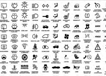
TIRE SAFETY INFORMATION
Tire Markings
1 — U.S. DOT Safety Standards Code (TIN) 2 — Size Designation 3 — Service Description
4 — Maximum Load
5 — Maximum Pressure 6 — Treadwear, Traction and Temperature Grades
NOTE: • P (Passenger) - Metric tire sizing is based on U.S. design standards. P-Metric tires have the letter “P†molded into the sidewall preceding the size designa- tion. Example: P215/65R15 95H. • European-Metric tire sizing is based on European design standards. Tires designed to this standard have the tire size molded into the sidewall beginning with the section width. The letter ⬙P⬙ is absent from this tire size designation. Example: 215/65R15 96H. • LT (Light Truck) - Metric tire sizing is based on U.S. design standards. The size designation for LT-Metric
STARTING AND OPERATING 319
tires is the same as for P-Metric tires except for the letters “LT†that are molded into the sidewall preced- ing the size designation. Example: LT235/85R16. • Temporary spare tires are high-pressure compact spares designed for temporary emergency use only. Tires designed to this standard have the letter “T†molded into the sidewall preceding the size designa- tion. Example: T145/80D18 103M. • High flotation tire sizing is based on U.S. design standards and it begins with the tire diameter molded into the sidewall. Example: 31x10.5 R15 LT.320 STARTING AND OPERATING Tire Sizing Chart
Size Designation:
EXAMPLE:
P = Passenger car tire size based on U.S. design standards â´–....blank....â´– = Passenger car tire based on European design standards LT = Light truck tire based on U.S. design standards T = Temporary spare tire 31 = Overall diameter in inches (in) 215 = Section width in millimeters (mm) 65 = Aspect ratio in percent (%)
— Ratio of section height to section width of tire
10.5 = Section width in inches (in) R = Construction code
— ⬙R⬙ means radial construction —⬙D⬙ means diagonal or bias construction
15 = Rim diameter in inches (in)
EXAMPLE:
STARTING AND OPERATING 321
Service Description:
95 = Load Index
— A numerical code associated with the maximum load a tire can carry
H = Speed Symbol
— A symbol indicating the range of speeds at which a tire can carry a load corresponding to its load index under certain operating conditions — The maximum speed corresponding to the speed symbol should only be achieved under specified operating conditions (i.e., tire pressure, vehicle loading, road conditions, and posted speed limits)
Load Identification:
â´–....blank....â´– = Absence of any text on the sidewall of the tire indicates a Standard Load (SL) tire Extra Load (XL) = Extra load (or reinforced) tire Light Load = Light load tire C, D, E = Load range associated with the maximum load a tire can carry at a specified pressure
Maximum Load — Maximum load indicates the maximum load this tire is designed to carry Maximum Pressure — Maximum pressure indicates the maximum permissible cold tire inflation pressure for this tire
322 STARTING AND OPERATING Tire Identification Number (TIN) The TIN may be found on one or both sides of the tire, however, the date code may only be on one side. Tires with white sidewalls will have the full TIN, including the date code, located on the white sidewall side of the tire.
Look for the TIN on the outboard side of black sidewall tires as mounted on the vehicle. If the TIN is not found on the outboard side, then you will find it on the inboard side of the tire.
EXAMPLE:
DOT MA L9 ABCD 0301
DOT = Department of Transportation
— This symbol certifies that the tire is in compliance with the U.S. Department of Transportation tire safety standards and is approved for highway use
MA = Code representing the tire manufacturing location (two digits) L9 = Code representing the tire size (two digits) ABCD = Code used by the tire manufacturer (one to four digits) 03 = Number representing the week in which the tire was manufactured (two digits)
—03 means the 3rd week.
01 = Number representing the year in which the tire was manufactured (two digits)
—01 means the year 2001
— Prior to July 2000, tire manufacturers were only required to have one number to represent the year in which the tire was manufactured. Example: 031 could represent the 3rd week of 1981 or 1991Tire Terminology And Definitions
B-Pillar
Term
Cold Tire Pressure
Maximum Inflation Pressure
Recommended Inflation Pressure
Tire Placard
STARTING AND OPERATING 323
Definition
The vehicle B-Pillar is a structural member of the body located between the front and rear door (of a four-door vehicle) running from the sill to the roof. Cold tire inflation pressure is defined as the tire pressure after the vehicle has not been driven for at least 3 hours, or driven less than 1 mile (1.6 km) after sitting for a three hour period. Inflation pressure is measured in units of PSI (pounds per square inch) or KPa (kilopascals). The maximum inflation pressure is the maximum permissible cold tire inflation pressure for this tire. The max inflation pressure is molded into the sidewall. Vehicle manufacturer’s recommended tire inflation pressure as shown on the tire placard. A paper label permanently attached to the vehicle showing the vehicle’s loading capacity, the original equipment tire size and the recommended inflation pressure.
324 STARTING AND OPERATING Tire Loading And Tire Pressure
Tire Placard Location NOTE: The proper cold tire inflation pressure is listed on the driver’s side B-Pillar.
Tire And Loading Information Placard
Tire and Loading Information Placard
Tire Placard Location
This placard tells you important information about the: 1) number of people that can be carried in the vehicle 2) total weight your vehicle can carry 3) tire size designed for your vehicle 4) cold tire inflation pressures for the front, rear, and spare tires. Loading The vehicle maximum load on the tire must not exceed the load carrying capacity of the tire on your vehicle. You will not exceed the tire’s load carrying capacity if you adhere to the loading conditions, tire size, and cold tire inflation pressures specified on the Tire and Loading Information placard and in the “Vehicle Loading†section of this manual. NOTE: Under a maximum loaded vehicle condition, gross axle weight ratings (GAWRs) for the front and rear
STARTING AND OPERATING 325
axles must not be exceeded. For further information on GAWRs, vehicle loading, and trailer towing, refer to “Vehicle Loading†in this section. To determine the maximum loading conditions of your vehicle, locate the statement “The combined weight of occupants and cargo should never exceed XXX lbs or XXX kg†on the Tire and Loading Information placard. The combined weight of occupants, cargo/luggage and trailer tongue weight (if applicable) should never exceed the weight referenced here. Steps For Determining Correct Load Limit 1. Locate the statement “The combined weight of occu- pants and cargo should never exceed XXX lbs or XXX kg†on your vehicle’s placard. 2. Determine the combined weight of the driver and passengers that will be riding in your vehicle.326 STARTING AND OPERATING 3. Subtract the combined weight of the driver and pas- sengers from XXX lbs or XXX kg. 4. The resulting figure equals the available amount of cargo and luggage load capacity. For example, if “XXX†amount equals 1,400 lbs (635 kg) and there will be five 150 lb (68 kg) passengers in your vehicle, the amount of available cargo and luggage load capacity is 650 lbs (295 kg) (since 5 x 150 = 750, and 1400 – 750 = 650 lbs [295 kg]). 5. Determine the combined weight of luggage and cargo being loaded on the vehicle. That weight may not safely exceed the available cargo and luggage load capacity calculated in Step 4. 6. If your vehicle will be towing a trailer, load from your trailer will be transferred to your vehicle. Consult this manual to determine how this reduces the available cargo and luggage load capacity of your vehicle.
NOTE: • The following table shows examples on how to calcu- late total load, cargo/luggage, and towing capacities of your vehicle with varying seating configurations and number and size of occupants. This table is for illustration purposes only and may not be accurate for the seating and load carry capacity of your vehicle. • For the following example, the combined weight of occupants and cargo should never exceed 865 lbs (392 kg).
STARTING AND OPERATING 327
328 STARTING AND OPERATING
WARNING!
Safety
Overloading of your tires is dangerous. Overloading can cause tire failure, affect vehicle handling, and increase your stopping distance. Use tires of the recommended load capacity for your vehicle. Never overload them.
TIRES — GENERAL INFORMATION
Tire Pressure Proper tire inflation pressure is essential to the safe and satisfactory operation of your vehicle. Three primary areas are affected by improper tire pressure:
WARNING!
cause collisions.
sult in over-heating and tire failure.
• Improperly inflated tires are dangerous and can • Under-inflation increases tire flexing and can re- • Over-inflation reduces a tire’s ability to cushion shock. Objects on the road and chuckholes can cause damage that result in tire failure. • Unequal tire pressures can cause steering prob- • Over-inflated or under-inflated tires can affect vehicle handling and can fail suddenly, resulting in loss of vehicle control.
lems. You could lose control of your vehicle.
(Continued)
WARNING! (Continued)
• Unequal tire pressures from one side of the ve- hicle to the other can cause the vehicle to drift to the right or left. • Always drive with each tire inflated to the recom-
mended cold tire inflation pressure.
Economy Improper inflation pressures can cause uneven wear patterns to develop across the tire tread. These abnormal wear patterns will reduce tread life resulting in a need for earlier tire replacement. Under-inflation also increases tire rolling resistance and results fuel consumption. Ride Comfort and Vehicle Stability Proper tire inflation contributes to a comfortable ride. Over-inflation produces a jarring and uncomfortable ride.
in higher
STARTING AND OPERATING 329
Tire Inflation Pressures The proper cold tire inflation pressure is listed on the left side “B†Pillar. Some vehicles may have Supplemental Tire Pressure Information for vehicle loads that are less than the maximum loaded vehicle condition. These pressure con- ditions will be found in the “Supplemental Tire Pressure Information†section of this manual. The pressure should be checked and adjusted as well as inspecting for signs of tire wear or visible damage at least once a month. Use a good quality pocket-type gauge to check tire pressure. Do not make a visual judgement when determining proper inflation. Radial tires may look properly inflated even when they are under-inflated.
330 STARTING AND OPERATING
CAUTION!
After inspecting or adjusting the tire pressure, al- ways reinstall the valve stem cap. This will prevent moisture and dirt from entering the valve stem, which could damage the valve stem.
Inflation pressures specified on the placard are always “cold tire inflation pressure.†Cold tire inflation pressure is defined as the tire pressure after the vehicle has not been driven for at least three hours or driven less than 1 mile (1.6 km) after a three hour period. The cold tire inflation pressure must not exceed the maximum infla- tion pressure molded into the tire sidewall. Check tire pressures more often if subject to a wide range of outdoor temperatures as tire pressures vary with temperature changes.
Tire pressures change by approximately 1 psi (7 kPa) per 12°F (7°C) of air temperature change. Keep this in mind when checking tire pressure inside a garage, especially in the Winter. Example: If garage temperature = 68°F (20°C) and the outside temperature = 32°F (0°C) then the cold tire inflation pressure should be increased by 3 psi (21 kPa), which equals 1 psi (7 kPa) for every 12°F (7°C) for this outside temperature condition. Tire pressure may increase from 2 to 6 psi (13 to 40 kPa) during operation. Do not reduce this normal pressure build up or your tire pressure will be too low. Tire Pressures For High Speed Operation The manufacturer advocates driving at safe speeds within posted speed limits. Where speed limits or condi- tions are such that the vehicle can be driven at high speeds, maintaining correct tire inflation pressure is very important. Increased tire pressure and reduced vehicle
loading may be required for high-speed vehicle opera- tion. Refer to original equipment or an authorized tire dealer for recommended safe operating speeds, loading and cold tire inflation pressures.
WARNING!
High speed driving with your vehicle under maxi- mum load is dangerous. The added strain on your tires could cause them to fail. You could have a serious collision. Do not drive a vehicle loaded to the maximum capacity at continuous speeds above 75 mph (120 km/h).
STARTING AND OPERATING 331
Radial Ply Tires
WARNING!
Combining radial ply tires with other types of tires on your vehicle will cause your vehicle to handle poorly. The instability could cause a collision. Al- ways use radial ply tires in sets of four. Never combine them with other types of tires.
Cuts and punctures in radial tires are repairable only in the tread area because of sidewall flexing. Consult your authorized tire dealer for radial tire repairs.
332 STARTING AND OPERATING Spare Tire Matching Original Equipped Tire and Wheel – If Equipped The spare tire of your vehicle is equivalent in look and function as the original equipment tire and wheel found on the front or rear axle of your vehicle. This spare tire may be used in the tire rotation for your vehicle. If your vehicle has an option for a spare tire matching original equipment tire and wheel, refer to the recommended tire rotation pattern in “Tire Rotation Recommendations†in “Starting and Operating†for further information. If your vehicle is not equipped with an original equip- ment tire and wheel as a spare, a non-matching tempo- rary emergency use spare may be equipped with your vehicle. Temporary use spares are engineered to be used only with your vehicle. Your vehicle may be equipped with one of the following types of non-matching tempo- rary use spares; compact, full size, or limited-use.
Do not install more than one non-matching temporary use spare tire/wheel on the vehicle at any given time.
CAUTION!
Because of the reduced ground clearance, do not take your vehicle through an automatic car wash with a compact, full size or limited-use temporary spare installed. Damage to the vehicle may result.
Compact Spare Tire – If Equipped The compact spare is for temporary emergency use only. You can identify if your vehicle is equipped with a compact spare by looking at the spare tire description on the Tire and Loading Information Placard located on the driver’s side door opening or on the sidewall of the tire. Compact spare tire descriptions begin with the letter “T†or “S†preceding the size designation. Example: T145/ 80D18 103M. T, S = Temporary Spare Tire
Since this tire has limited tread life the original equip- ment tire should be repaired (or replaced) and reinstalled on your vehicle at the first opportunity. Do not install a wheel cover or attempt to mount a conventional tire on the compact spare wheel, since the wheel is designed specifically for the compact spare. Do not install more than one compact spare tire/wheel on the vehicle at any given time
WARNING!
Compact spares are for temporary emergency use only. With these spares, do not drive more than 50 mph (80 km/h). Temporary use spares have limited tread life. When the tread is worn to the tread wear indicators, the temporary use spare tire needs to be replaced. Be sure to follow the warnings, which apply to your spare. Failure to do so could result in spare tire failure and loss of vehicle control.
STARTING AND OPERATING 333
Full Size Spare – If Equipped The full size spare is for temporary emergency use only. This tire may look like the original equipped tire on the front or rear axle of your vehicle, but it is not. This spare tire may have limited tread life. When the tread is worn to the tread wear indicators, the temporary use full size spare tire needs to be replaced. Since it is not the same as your original equipment tire, replace (or repair) the original equipment tire and reinstall on the vehicle at the first opportunity. Limited-Use Spare – If Equipped The limited-use spare tire is for temporary emergency use only. This tire is identified by a label located on the limited-use spare wheel. This label contains the driving limitations for this spare. This tire may look like the original equipped tire on the front or rear axle of your vehicle, but it is not. Installation of this limited-use spare tire affects vehicle handling. Since it is not the same as
334 STARTING AND OPERATING your original equipment tire, replace (or repair) the original equipment tire and reinstall on the vehicle at the first opportunity.
WARNING!
Limited-use spares are for emergency use only. In- stallation of this limited-use spare tire affects vehicle handling. With this tire, do not drive more than the speed listed on the limit-use spare wheel. Keep inflated to the cold tire inflation pressure listed on your Tire and Loading Information Placard located on the driver’s side door opening. Replace (or repair) the original equipment tire at the first opportunity and reinstall it on your vehicle. Failure to do so could result in loss of vehicle control.
Tire Spinning When stuck in mud, sand, snow, or ice conditions, do not spin your vehicle’s wheels faster than 30 mph (48 km/h) or for longer than 30 seconds continuously without stopping when you are stuck. Refer to “Freeing A Stuck Vehicle†in “What To Do In Emergencies†for further information.
WARNING!
Fast spinning tires can be dangerous. Forces gener- ated by excessive wheel speeds may cause tire dam- age or failure. A tire could explode and injure some- one. Do not spin your vehicle’s wheels faster than 30 mph (48 km/h) or for more than 30 seconds continuously when you are stuck, and do not let anyone near a spinning wheel, no matter what the speed.
Tread Wear Indicators Tread wear indicators are in the original equipment tires to help you in determining when your tires should be replaced.
1 — Worn Tire 2 — New Tire
STARTING AND OPERATING 335
These indicators are molded into the bottom of the tread grooves. They will appear as bands when the tread depth becomes 1/16 in (2 mm). When the tread is worn to the tread wear indicators, the tire should be replaced. Life Of Tire The service life of a tire is dependent upon varying factors including, but not limited to: • Driving style • Tire pressure • Distance drivenWARNING!
Tires and the spare tire should be replaced after six years, regardless of the remaining tread. Failure to follow this warning can result in sudden tire failure. You could lose control and have a collision resulting in serious injury or death.
336 STARTING AND OPERATING Keep dismounted tires in a cool, dry place with as little exposure to light as possible. Protect tires from contact with oil, grease, and gasoline. Replacement Tires The tires on your new vehicle provide a balance of many characteristics. They should be inspected regularly for wear and correct cold tire inflation pressure. The manu- facturer strongly recommends that you use tires equiva- lent to the originals in size, quality and performance when replacement is needed. (Refer to the paragraph on “Tread Wear Indicatorsâ€). Refer to the “Tire and Loading Information†placard for the size designation of your tire. The service description and load identification will be found on the original equipment tire. Failure to use equivalent replacement tires may adversely affect the safety, handling, and ride of your vehicle. We recommend that you contact your original equipment or an autho- rized tire dealer with any questions you may have on tire specifications or capability.
WARNING!
• Do not use a tire, wheel size or rating other than that specified for your vehicle. Some combinations of unapproved tires and wheels may change sus- pension dimensions and performance characteris- tics, resulting in changes to steering, handling, and braking of your vehicle. This can cause unpredict- able handling and stress to steering and suspen- sion components. You could lose control and have a collision resulting in serious injury or death. Use only the tire and wheel sizes with load ratings approved for your vehicle. • Never use a tire with a smaller load index or capacity other than what was originally equipped on your vehicle. Using a tire with a smaller load index could result in tire overloading and failure. You could lose control and have a collision.
(Continued)
WARNING! (Continued)
• Failure to equip your vehicle with tires having adequate speed capability can result in sudden tire failure and loss of vehicle control.
CAUTION!
Replacing original tires with tires of a different size may result in false speedometer and odometer read- ings.
TIRE CHAINS Due to limited clearance, tire chains are not recom- mended.
CAUTION!
Damage to the vehicle may result if tire chains are used.
STARTING AND OPERATING 337
SNOW TIRES Some areas of the country require the use of snow tires during the winter. All season tires can be identified by the M+S designation on the tire sidewall. If you need snow tires, select tires equivalent in size and type to the original equipment tires. Use snow tires only in sets of four; failure to do so may adversely affect the safety and handling of your vehicle. Snow tires generally have lower speed ratings than what was originally equipped with your vehicle and should not be operated at sustained speeds over 75 mph (120 km/h). For speeds above 75 mph (120 km/h) refer to original equipment or an authorized tire dealer for recommended safe operating speeds, loading and cold tire inflation pressures. While studded tires improve performance on ice, skid and traction capability on wet or dry surfaces may be
338 STARTING AND OPERATING poorer than that of non-studded tires. Some states pro- hibit studded tires; local laws should be checked before using these tire types.
therefore,
TIRE ROTATION RECOMMENDATIONS The tires on the front and rear of your vehicle operate at different loads and perform different steering, driving, and braking functions. For these reasons, they wear at unequal rates. These effects can be reduced by timely rotation of tires. The benefits of rotation are especially worthwhile with aggressive tread designs such as those on all season type tires. Rotation will increase tread life, help to maintain mud, snow and wet traction levels, and contribute to a smooth, quiet ride. Refer to the “Maintenance Schedule†for the proper maintenance intervals. The reasons for any rapid or unusual wear should be corrected prior to rotation being performed.
The suggested rotation method is the “rearward cross†shown in the following diagram. This rotation pattern does not apply to some directional tires that must not be reversed.
Tire Rotation
TIRE PRESSURE MONITORING SYSTEM (TPMS) The Tire Pressure Monitor System (TPMS) will warn the driver of a low tire pressure based on the vehicle recom- mended cold placard pressure. The tire pressure will vary with temperature by about 1 psi (6.9 kPa) for every 12°F (6.5°C). This means that when the outside temperature decreases, the tire pressure will decrease. Tire pressure should always be set based on “cold inflation tire pressureâ€. This is defined as the tire pressure after the vehicle has not been driven for at least three hours, or driven less than 1 mile (1.6 km) after a three hour period. The cold tire inflation pressure must not exceed the maximum inflation pressure molded into the tire sidewall. Refer to “Tires – General Information†in “Starting and Operating†for information on how to properly inflate the vehicle’s tires. The tire pressure will also increase as the vehicle is driven - this is normal and there should be no adjustment for this increased pres- sure.
STARTING AND OPERATING 339
The TPMS will warn the driver of a low tire pressure if the tire pressure falls below the low-pressure warning limit for any reason, including low temperature effects, or natural pressure loss through the tire. The TPMS will continue to warn the driver of low tire pressure as long as the condition exists, and will not turn off until the tire pressure is at or above the recommended cold placard pressure. Once the low tire pressure warn- ing (Tire Pressure Monitoring Telltale Light) illuminates, you must increase the tire pressure to the recommended cold placard pressure in order for the Tire Pressure Monitoring Telltale Light to turn off. The system will automatically update and the Tire Pressure Monitoring Telltale Light will turn off once the system receives the updated tire pressures. The vehicle may need to be driven for up to 20 minutes above 15 mph (24 km/h) in order for the TPMS to receive this information.340 STARTING AND OPERATING For example, your vehicle may have a recommended cold (parked for more than three hours) placard pressure of 30 psi (207 kPa). If the ambient temperature is 68°F (20°C) and the measured tire pressure is 27 psi (186 kPa), a temperature drop to 20°F (-7°C) will decrease the tire pressure to approximately 23 psi (158 kPa). This tire pressure is sufficiently low enough to turn ON the Tire Pressure Monitoring Telltale Light. Driving the vehicle may cause the tire pressure to rise to approximately 27 psi (186 kPa), but the Tire Pressure Monitoring Telltale Light will still be ON. In this situation, the Tire Pressure Monitoring Telltale Light will turn OFF only after the tires are inflated to the vehicle’s recommended cold placard pressure value.
CAUTION!
• The TPMS has been optimized for the original equipment tires and wheels. TPMS pressures and warnings have been established for the tire size equipped on your vehicle. Undesirable system operation or sensor damage may result when us- ing replacement equipment that is not of the same size, type, and/or style. Aftermarket wheels can cause sensor damage. Do not use aftermarket tire sealants or balance beads if your vehicle is equipped with a TPMS, as damage to the sensors may result. • After inspecting or adjusting the tire pressure, always reinstall the valve stem cap. This will prevent moisture and dirt from entering the valve stem, which could damage the Tire Pressure Moni- toring Sensor.
while adjusting your tire pressure.
NOTE: • The TPMS is not intended to replace normal tire care and maintenance or to provide warning of a tire failure or condition. • The TPMS should not be used as a tire pressure gauge • Driving on a significantly under-inflated tire causes the tire to overheat and can lead to tire failure. Under-inflation also reduces fuel efficiency and tire tread life, and may affect the vehicle’s handling and stopping ability. • The TPMS is not a substitute for proper tire mainte- nance, and it is the driver’s responsibility to maintain correct tire pressure using an accurate tire gauge, even if under-inflation has not reached the level to trigger illumination of the Tire Pressure Monitoring Telltale Light.
STARTING AND OPERATING 341
• Seasonal temperature changes will affect tire pressure, and the TPMS will monitor the actual tire pressure in the tire.
Base System
This is the TPMS warning indicator located in the instrument cluster.
The TPMS uses wireless technology with wheel rim mounted electronic sensors to monitor tire pressure lev- els. Sensors, mounted to each wheel as part of the valve stem, transmit tire pressure readings to the Receiver Module. It is particularly important for you to check the NOTE: tire pressure in all of the tires on your vehicle regularly and to maintain the proper pressure. The TPMS consists of the following components: • Receiver Module
342 STARTING AND OPERATING
• Four Tire Pressure Monitoring Sensors • Tire Pressure Monitoring Telltale Light Tire Pressure Monitoring Low Pressure Warnings The Tire Pressure Monitoring Telltale Light will illumi- nate in the instrument cluster, a LOW TIRE message will be displayed for a minimum of five seconds, and an audible chime will be activated when one or more of the four active road tire pressures are low. Should this occur, you should stop as soon as possible, check the inflation pressure of each tire on your vehicle, and inflate each tire to the vehicle’s recommended cold placard pressure value. The system will automatically update and the Tire Pressure Monitoring Light will extinguish and the LOW TIRE message will turn off once the updated tire pres- sures have been received. The vehicle may need to be driven for up to 20 minutes above 15 mph (24 km/h) to receive this information.
Check TPMS Warnings The Tire Pressure Monitoring Telltale Light will flash on and off for 75 seconds and remain on solid when a system fault is detected. The system fault will also sound a chime. If the ignition key is cycled, this sequence will repeat providing the system fault still exists. The Tire Pressure Monitoring Telltale Light will turn off when the fault condition no longer exists. A system fault can occur with any of the following scenarios: 1. Jamming due to electronic devices or driving next to facilities emitting the same radio frequencies as the TPM sensors. 2. Installing some form of aftermarket window tinting that affects radio wave signals. 3. Snow or ice around the wheels or wheel housings. 4. Using tire chains on the vehicle. 5. Using wheels/tires not equipped with TPM sensors.
NOTE: Your vehicle is equipped with a compact spare wheel and tire assembly. 1. The compact spare tire does not have a tire pressure monitoring sensor. Therefore, the TPMS will not monitor the tire pressure in the compact spare tire. 2. If you install the compact spare tire in place of a road tire that has a pressure below the low-pressure warning limit, upon the next ignition key cycle, a chime will sound and the Tire Pressure Monitoring Telltale Light and LOW TIRE message will still turn ON due to the low tire. 3. However, after driving the vehicle for up to 20 min- utes above 15 mph (24 km/h), the Tire Pressure Moni- toring Telltale Light will flash on and off for 75 seconds and then remain on solid.
STARTING AND OPERATING 343
4. For each subsequent ignition key cycle, a chime will sound and the Tire Pressure Monitoring Telltale Light will flash on and off for 75 seconds and then remain on solid. 5. Once you repair or replace the original road tire and reinstall it on the vehicle in place of the compact spare tire, the TPMS will update automatically and the Tire