- 2009 Hyundai Tucson Owners Manuals
- Hyundai Tucson Owners Manuals
- 2005 Hyundai Tucson Owners Manuals
- Hyundai Tucson Owners Manuals
- 2008 Hyundai Tucson Owners Manuals
- Hyundai Tucson Owners Manuals
- 2010 Hyundai Tucson Owners Manuals
- Hyundai Tucson Owners Manuals
- 2012 Hyundai Tucson Owners Manuals
- Hyundai Tucson Owners Manuals
- 2011 Hyundai Tucson Owners Manuals
- Hyundai Tucson Owners Manuals
- Download PDF Manual
-
driven to get medical assistance, continue to rinse your eyes by using a sponge or soft cloth saturated with water.
o If you swallow battery fluid, drink a large quantity of water or milk followed by milk of magnesia, eat a raw egg or drink vegetable oil. Get medical assistance as soon as possible.
While batteries are being charged (either by a battery charger or by the vehicle's generator), they produce explosive gases. Always ob- serve these warnings to prevent injuries from occurring:
G210B03A-AAT Checking the Battery
Keep the battery clean. Any evidence of corro- sion around the battery posts or terminals should be removed using a solution of house- hold baking soda and warm water. After the battery terminals are dry, cover them with a light coating of grease.
PROPOSITION 65 WARNING: Battery posts, terminals, and related acces- sories contain lead and lead compounds, chemicals known to the State of California to cause cancer and reproductive harm. Batteries also contain other chemicals known to the State of California to cause cancer. Wash hands after handling.
o Charge batteries only in a well ventilated
o Do not permit flames, sparks or smoking in
area.
the area.
o Keep children away from the area.
6 DO-IT-YOURSELF MAINTENANCE 24
CHECKING ELECTRIC COOLING FANS G220A01A-AAT
WARNING:
The cooling fan is controlled by engine coolant temperature and may sometimes operate even when the engine is not run- ning. Use extreme caution when working near the blades of the cooling fan, so that you are not injured by a rotating fan blade. As the engine coolant temperature de- creases the fan will automatically shut off. This is a normal condition.
POWER STEERING FLUID LEVEL
G220B01A-AAT Checking Engine Cooling Fan
G230A03A-AAT
The engine cooling fan should come on auto- matically if the engine coolant temperature is high.
G220C01A-AAT Checking Condenser Cooling Fan
The condenser cooling fan should come on automatically whenever the air conditioning is in operation.
G230A01JM
The power steering fluid level should be checked regularly. To check the power steering fluid level, be sure the engine is "OFF", then check to make certain that the power steering fluid level is between the "MAX" and "MIN" level markings on the fluid reservoir.
NOTE: Grinding noise from the power steering pump may be heard immediately after the engine is started in extremely cold condi- tions (below - 4°F). If the noise stops during warm up, there is no abnormal function in the system. It is due to a power steering fluid characteristic in extremely cold condi- tions.
HEADLIGHT AIMING ADJUSTMENT
G290A02O-AAT Before performing aiming adjustment, make sure of the following. 1. Keep all tires inflated to the correct pressure. 2. Place the vehicle on level ground and press the front bumper & rear bumper down sev- eral times. Place vehicle at a distance of 118 in. (3m) from the test wall.
3. See that the vehicle is unloaded (except for full levels of coolant, engine oil and fuel, and spare tire, jack, and tools). Have the driver or equivalent weight placed in driver's seat. 4. Clean the head light lenses and turn on the
headlights (Low beam).
5. Open the hood.
DO-IT-YOURSELF MAINTENANCE
25
Vertical aiming
Horizontal aiming
G290A01JM
6. Draw a vertical line (through the center of each headlight beam pattern) and a horizon- tal line (through the center of each headlight beam pattern) on the aiming screen. And then, draw a parallel line at 0.8 in. (21
mm) under the horizontal line.7. Adjust each cut-off line of the low beam to the parallel line with a phillips screwdriver - VERTICAL AIMING.
WARNING:
Horizontal aiming should be adjusted by an authorized Hyundai dealer.
Recommended Fluid Use PSF-3 type fluid
NOTE: Do not start the engine when the power steering oil reservoir is empty.
G240A01A-AAT POWER STEERING HOSES
It is suggested that you check the power steer- ing hose connections for fluid leakage at those intervals specified in the vehicle maintenance schedule in Section 5. The power steering hoses should be replaced if there is severe surface cracking, pulling, scuffing or worn spots. Deterioration of the hose could cause premature failure.
G250A01A-AAT FOR MORE INFORMATION ABOUT YOUR HYUNDAI
If you desire additional information about main- taining and servicing your Hyundai, you may purchase a factory Shop Manual at your Hyundai dealer's parts department. This is the same manual used by dealership technicians and while it is highly technical it can be useful in obtaining a better understanding of your car and how it works.
SPECIFICATION:
"H"; Horizontal center line of headlights from ground: 35.6 in.(904 mm)
"W"; Distance between each headlight center: 53.4 in.(1,356 mm)
"L"; Distance between the headlights and the wall that the lights are tested against: 118 in. (3,000 mm).
6 DO-IT-YOURSELF MAINTENANCE 26
G290B01JM-AAT Adjustment After Headlight Assembly Replacement
Horizontal line
30 mm
Vertical line
"P"
C u t - o f f line
Ground line
G290B01B
If the vehicle has had front body repair and the headlight assembly has been replaced, the headlight aiming should be checked using an aiming chart as shown in the illustration. Turn on the headlight switch. (Low Beam Position)
1. Adjust headlights so that main axis of light is parallel to center line of the body and is aligned with point "P" shown in the illustration. 2. Dotted lines in the illustration show the center
of headlights.
REPLACEMENT OF LIGHT BULBS
G260A02A-AAT Before attempting to replace a light bulb, be sure the switch is turned to the "OFF" position. The next paragraph shows how to reach the light bulbs so they may be changed. Be sure to replace the burned-out bulb with one of the same number and wattage rating.
See page 6-34 for the wattage description.
CAUTION:
Keep the lamps out of contact with petro- leum products, such as oil, gasoline, etc.
G270A02O-AAT Headlight and Front Turn Signal Light
1. Allow the bulb to cool. Wear eye protection. 2. Open the engine hood. 3. Always grasp the bulb by its plastic base,
avoid touching the glass.
4. Using a socket wrench of the correct size, remove the headlight assembly mounting bolts.
HJM5012
DO-IT-YOURSELF MAINTENANCE
27
6. Turn the plastic cover counterclockwise
and remove it.
HJM5013
5. Disconnect the power cord from the bulbbase in the back of the headlight.
7. Disconnect the connector from the bulb
base in the back of the headlight.
HJM5017
HJM5016
6 DO-IT-YOURSELF MAINTENANCE 28
G270B01JM-AAT Rear Combination Light
G270A03O
WARNING:
This halogen bulb contains gas under pres- sure and if impacted could shatter, result- ing in flying fragments. Always wear eye protection when servicing the bulb. Protect the bulb against abrasions or scratches and against liquids when lighted. Turn the bulb on only when installing in a headlight. Replace the headlight if damaged or cracked. Keep the bulb out of the reach of children and dispose of the used bulb with care.
HJM5020
HJM5021
HJM5018
8. Push the bulb spring to remove the headlightbulb.
9. Remove the protective cap from the re- placement bulb and install the new bulb by matching the plastic base with the headlight hole. Reattach the bulb spring and recon- nect the connector.
10.Use the protective cap and carton to prompt-
ly dispose of the old bulb.
11.Check for proper headlight aim. 12.To replace the front turn signal light bulb, remove from the bulb holder and install the new bulb. Do not touch the glass of the new bulb.
DO-IT-YOURSELF MAINTENANCE
29
3. Disconnect the power cord.
HJM5049
1. Open the tail gate. 2. Remove the mounting screws as shown
with a phillips screwdriver.
G270I02JM-GAT Front fog Light (If installed)
(1)
(2)
(3)
(4)
HJM5022
3. To replace the rear combination light (stop/ tail light, turn signal light, back-up light, side mark light), take it out from the bulb holder by turning it counterclockwise.
(1) Stop/Tail light (2) Turn signal light (3) Back-up light (4) Tail light
4.
Install the new bulb.
HJM5047
1. Remove the cover with a phillips screwdriver.
2. Remove the bolts with a wrench.
4. Replace to the new bulb.
HJM5048
HJM5050
6 DO-IT-YOURSELF MAINTENANCE 30
G270C02TB-GAT Luggage Compartment Light (If Installed)
G270C02JM-AAT Cargo Light
1. Remove the cover with a flat blade screw
driver.
G270C01JM
2. Disconnect the power cord.
G270C02JM
1. Open the tail gate. 2. Remove the cover with a flat blade screw-
driver.
HJM5023
3. Replace to the new bulb.
HTB284
G270E01O-AAT Front Side Marker Light
DO-IT-YOURSELF MAINTENANCE
31
3. Replace with a new bulb.
HJM5024
G270E02HR
G270E01JM 1. Remove the cover with a phillips screw-
driver.
2. Disconnect the connector.
3. Replace with a new bulb.
G270E03HR
6 DO-IT-YOURSELF MAINTENANCE 32
G270G01O-AAT Interior Light
G270H01O-AAT Glove Box Illuminated Light
HJM5025
2. Replace with a new bulb.
HJM5026
1. Remove the cover with a flat blade screw-
driver.
1. Open the glove box. 2. Remove the cover with a flat blade screw-
driver.
HJM5045
DO-IT-YOURSELF MAINTENANCE
33
3. Disconnect the connector. 4. Replace with a new bulb.
HJM5039
HTB284
6 DO-IT-YOURSELF MAINTENANCE 34
BULB WATTAGE
G280A01JM-AAT
No.
Part Name
Front Postion Light Glove Box Illuminated Light Head Light (Low/High) Interior Light
Map Light Room Light
Front Fog Light (If installed) Turn Signal Light Side Marker Front Door Edge Warning Light (If installed)
Wattage
10
55/60
10
10
27
21No.
10
11
12
13
14
15Part Name
Wattage
Cargo Light
High Mounted Rear Stop Light (LED Type)
Luggage Compartment Light Turn Signal Light Back-up Light License Plate Light Stop/Tail Light
2.4
10
A TYPE B TYPE 10
21
2121/5
G280A01JM-U
FUSE PANEL DESCRIPTION
G200C01JM-GAT Engine Compartment
DO-IT-YOURSELF MAINTENANCE
35
DESCRIPTION
FUSE
RATING
PROTECTED COMPONENTS
FUSIBLE
LINK
FUSE
IGN ECU
BATT #1
C/FAN ABS #1
ABS #2
BLOWER BATT #2INJ
SNSR DRL
F/FOG HORN A/CON H/LP (HI)
H/LP (LOW)
30A 30A 50A 50A 30A 40A 30A 30A 15A 10A 15A 15A 15A 15A 15A 15A
Start relay, Ignition switch Engine control, Fuel pump , A/C, Generator, ATM Ignition switch, Power connector Cooling fan ABS, ESP ABS, ESP Blower Ignition switch, Power connector Injector Cooling fan, Stop lamp switch, Oxygen sensor, ECM/PCM DRL Front fog lamp Horn, Siren A/C Head lamp (HIGH) Head lamp (LOW)
NOTE: Not all fuse panel descriptions in this manual may be applicable to your vehicle. It is accurate at the time of printing. When you inspect the fuse box on your vehicle, refer to the fuse box label.
G200C01JM
6 DO-IT-YOURSELF MAINTENANCE 36
G200E01JM-AAT Inner Panel
G200E01JM
DO-IT-YOURSELF MAINTENANCE
37
FUSE
FUSE
RATING
P/WDW-LH P/WDW-RH
TAIL RH RR HTR A/BAG
CLUSTER TAIL LH AUDIO
C/LIGHTER & P/OUTLET
SPARE RR FOG HTD MIRR
AUDIO IG COIL IMMO
P/OUTLET
S/HTR
A/CON SW
START
30A 30A 10A 30A 15A 10A 10A 10A
20A
15A 10A 10A 10A 20A 10A 15A 10A 20A 10A 10A
PROTECTED COMPONENTS
Left power window Right power window Right rear combination lamp, Glove box lllumination Rear defogger SRS control Instrument cluster, ETACM/TACM Left head lamp, Left rear combination lamp, License lamp Digital clock, Audio, Power outside mirror folding module, Power outside mirror & mirror folding switch
Cigarette lighter
(SPARE) Rear fog lamp Left/Right power outsider mirror & mirror folding motor, Rear defogger switch Audio Ignition coil (2.7 L) Immobilizer control module (2.7 L) Rear power outlet (Not used) Seat warmer A/C control module (Manual A/C) Theft alarm relay, Transaxle range switch, lgnition lock switch
6 DO-IT-YOURSELF MAINTENANCE 38
FUSE
IG-SW
ROOM LP
AMP T/SIG
A/BAG IND RR WIPER
A/CON
IGN
HAZARD S/ROOF
STOP H/FREE
ECU
FF WIPER
4WD
DEICER
TCU ABS
FUSE
RATING
PROTECTED COMPONENTS
30A 10A 20A 10A 10A 15A 10A 10A 10A 20A 15A 10A 10A 20A 20A 15A 10A 10A
Ignition switch Room lamp, A/C control module, Digital clock, ETACM/TACM Key remind switch Audio Hazard switch, Auto light & Photo sensor, Transaxle range switch Instrument cluster Safety relay Sunroof controller, A/C control module, Blower relay, ETACM/TACM PTC heater relay, Fuel filter heater relay, DRL CONTROL MODULE, head LAMP RELAY Hazard switch, Hazard relay, Immobilizer control module (2.7 L) Sunroof, Door lock/unlock relay Stop lamp switch, Power outside mirror folding module (Not used) Cruise control, Stop lamp, TCS, ESP, 4WD ECM, ECM, PCM, TCM, Vehicle speed sensor Front wiper, Multifunction switch 4WD/ECM Windshield defogger TCM (2.7 L) G-Sensor, ESP, ABS
EMISSION CONTROL SYSTEMS
Emission Control System ............................................. 7-2
Catalytic Converter ....................................................... 7-37 EMISSION CONTROL SYSTEMS
EMISSION CONTROL SYSTEM
H010A02O-AAT Your Hyundai is equipped with an emission control system to meet all requirements of the U.S. Environmental Protection Agency or Cali- fornia Air Resources Board. There are three emission control systems which are as follows.
(1) Crankcase emission control system (2) Evaporative emission control system (3) Exhaust emission control system
In order to assure the proper function of the emission control systems, it is recommended that you have your car inspected and main- tained by an authorized Hyundai dealer in ac- cordance with the maintenance schedule in this manual.
Caution for the Inspection and Maintenance Test (V6 Vehicle with Traction Control Sys- tem)
o To prevent the vehicle from misfiring during dynamometer testing, discon- nect the ABS connector in the engine compartment. (2.7 V6 only)
o For more information, see shop manual
(Wheel Speed Sensor).
o After dynamometer testing is completed, erase the ABS/TCS DTC (Diagnotic Trouble Code) with a GST (Generic Scan Tool) or Hi-Scan Pro.
H010B01A-AAT 1. Crankcase Emission Control
Canister
System
The positive crankcase ventilation system is employed to prevent air pollution caused by blow-by gases being emitted from the crank- case. This system supplies filtered air to the crankcase through the air intake hose. Inside the crankcase, the fresh air mixes with blow-by gases, which then pass through the PCV valve and into the induction system.
H010C01S-AAT 2. Evaporative Emission Control (Includ- ing ORVR: Onboard Refueling Vapor Recovery) System
The Evaporative Emission Control System is designed to prevent fuel vapors from escaping into the atmosphere. (The ORVR system is designed to allow the vapors from the fuel tank to be loaded into a canister while refueling at the gas station, pre- venting the escape of fuel vapors into the atmosphere.)
Fuel vapors generated inside the fuel tank are absorbed and stored in the canister. When the engine is running, the fuel vapors absorbed in the canister are drawn into the induction system through the purge control solenoid valve.
Purge Control Solenoid Valve (PCSV)
The purge control solenoid valve is controlled by the Engine Control Module (ECM); when the engine coolant temperature is low during idling, the PCSV closes so that evaporated fuel is not taken into the engine. After the engine warms- up during ordinary driving, the PCSV opens to introduce evaporated fuel to the engine.
H010D01A-AAT 3. Exhaust Emission Control System
The Exhaust Emission Control System is a highly effective system which controls exhaust emissions while maintaining good vehicle performace.
EMISSION CONTROL SYSTEMS
WARNING:
o Remember that your Hyundai dealer is
your best source of assistance.
o Do not stop your Hyundai over any com- bustible material such as grass, paper, leaves or rags. These materials might contact the hot catalytic converter and a fire might result.
CATALYTIC CONVERTER
H020A01A-AAT
Catalytic Converter
H020A01JM
All Hyundai vehicles are equipped with a mono- lith type three-way catalytic converter to re- duce the carbon monoxide, hydrocarbons and nitrogen oxides contained in the exhaust gas. Exhaust gases passing through the catalytic converter cause it to operate at a very high temperature. The introduction of large amounts of unburned gasoline into the exhaust may cause the catalytic converter to overheat and create a fire hazard. This risk may be reduced by observing the following:
WARNING:
o Use unleaded fuel only. o Maintain the engine in good operating condition. Extremely high catalytic con- verter temperatures can result from im- proper operation of the electrical, igni- tion or multiport electronic fuel injec- tion.
o If your engine stalls, pings, knocks, or is hard to start, have your Hyundai dealer inspect and repair the problem as soon as possible.
o Avoid driving with a very low fuel level. Running out of gasoline may cause the engine to misfire and result in damage to the catalytic converter.
o Avoid idling the engine for periods
longer than 10 minutes.
o The vehicle should not be pushed or pulled to get started. This may cause the catalytic converter to overheat and cre- ate a fire hazard.
o Do not touch the catalytic converter or any other part of the exhaust system while the catalytic converter is hot. Shut off the engine, wait for at least one hour before touching the catalytic converter or any other part of the exhaust system.
CONSUMER INFORMATION
Vehicle Identification Number (VIN) .............................. 8-2
Engine Number ............................................................. 8-2
Tire Information ............................................................. 8-2
Recommended Inflation Pressures ............................... 8-3
Tire Sidewall Labeling ................................................... 8-4
Tire Terminology and Definitions ................................... 8-6
Snow Tires .................................................................... 8-8
Tire Chains.................................................................... 8-9
Tire Rotation.................................................................. 8-9
Tire Balancing ............................................................... 8-9
Tire Traction ................................................................ 8-10
When to Replace Tires ............................................... 8-10
Tire Maintenance ........................................................ 8-11
Spare Tire and Tools................................................... 8-11
Warranties for Your Hyundai Vehicle .......................... 8-11
Consumer Information ................................................. 8-12
Reporting Safety Defects ............................................ 8-148 CONSUMER INFORMATION & REPORTING SAFETY DEFECTS
VEHICLE IDENTIFICATION NUMBER (VIN)
I010A02JM-AAT
The vehicle identification number (VIN) is the number used in registering your car and in all legal matters pertaining to its ownership, etc. It can be found in three different places on your car:
ENGINE NUMBER
I010B01A-AAT
DOHC (I4)
V6
1. Lower side of the front passenger seat under
the carpet.
2. On the left top side of the instrument panel where it can be seen by looking down through the windshield.
3. On the lower side of the left center pillar outer
panel.
I010B01GK The engine number is stamped on the engine block as shown in the drawing.
I010A03JM
I010A02JM
Tire label located on the driver's side of the center pillar outer panel gives the cold tire pressures recommended for your vehicle with the original tire size, the number of people that can be in your vehicle and vehicle capacity weight.
TIRES
I020A02A-AAT TIRE INFORMATION The tires supplied on your new Hyundai are chosen to provide the best perfor- mance for normal driving. If you ever have questions about your tire warranty and where to obtain ser- vice, see the tire manufacture's booklet included with your vehicle's Owner's Manual Literature Kit.
I030A01JM-AAT
RECOMMENDED INFLATION PRES- SURES
I030A01JM These pressures were chosen to pro- vide the most satisfactory combination of ride comfort, tire wear and stability under normal conditions. Tire pressures should be checked at least monthly. Proper tire inflation pressures should be maintained for these reasons:
HJM1032
CONSUMER INFORMATION & REPORTING SAFETY DEFECTS
WARNING:
o Lower-than-recommended tire pressures cause uneven tread wear, poor handling, poor fuel economy or tire failure.
o Higher-than-recommended tire pressures can cause poor han- dling, uneven tread wear or tire failure.
CAUTION:
Always observe the following:
o Check pressures when the tires are cold. (After the vehicle has been parked for at least three hours or hasn't been driven more than one mile (1.6 km) since starting up.)
8 CONSUMER INFORMATION & REPORTING SAFETY DEFECTS
o Check the pressure of your spare tire each time you check the pres- sure of other tires.
o Never overload your vehicle. Be especially careful about overload- ing if you equip your vehicle with a luggage rack.
o Worn, old tires can cause acci- dents. If your tread is badly worn, or if your tires have been dam- aged, replace them.
I035A01JM-AAT
CHECKING TIRE INFLATION PRES- SURE Check your tires once a month or more. Also, check the tire pressure of the spare tire.
How to Check Use a good quality gage to check tire pressure. You can not tell if your tires are properly inflated simply by looking
at them. Radial tires may look properly inflated even when they're underinflated. Check the tire's inflation pressure when the tires are cold. - "Cold" means your vehicle has been sitting for at least three hours or driven no more than 1
mile (1.6 km). Remove the valve cap from the tire valve stem. Press the tire gage firmly onto the valve to get a pressure mea- surement. If the cold tire inflation pres- sure matches the recommended pres- sure on the tire and loading information label, no further adjustment is neces- sary. If the pressure is low, add air until you reach the recommended amount. If you overfill the tire, release air by pushing on the metal stem in the center of the tire valve. Recheck the tire pres- sure with the tire gage. Be sure to put the valve caps back on the valve stems. They help prevent leaks by keeping out dirt and moisture.I030B01JM-AAT TIRE SIDEWALL LABELING
5, 6
I030B04JM
Federal law requires tire manufacturers to place standardized information on the sidewall of all tires. This information identifies and describes the fundamen- tal characteristics of the tire and also provides the tire identification number (TIN) for safety standard certification. The TIN can be used to identify the tire in case of a recall.
CONSUMER INFORMATION & REPORTING SAFETY DEFECTS
1. Manufacturer or Brand name
o Manufacturer or Brand name is
shown.
2. Tire size (example: P235/60R16 99T) o The "P" indicates the tire is de- signed for passenger vehicles. A "T" is the designation for a tempo- rary spare tire.
o Three-digit number (235): This num- ber gives the width in millimeters of the tire from sidewall edge to sidewall edge.
o Two-digit number (60): This num- ber, known as the aspect ratio, gives the tire's ratio of height to width.
o R: The "R" stands for radial. o Two-digit number (16): This num- ber is the wheel or rim diameter in inches.
o Two (or three) digit number (99): This number is the tire's load in- dex. It is a measurement of how much weight each tire can sup- port.
o T: Speed Rating. The speed rating denotes the speed at which a tire is designed to be driven for extended periods of time. The ratings range from "A" to "Z" (98 to 186 MPH). 3. TIN (Tire Identification Number) for new tire (example: DOT XX XX XXX XXXX) o DOT: Abbreviation for the "Depart- ment of Transportation". The sym- bol can be placed above, below or to the left or right of the Tire Iden tification Number. Indicates tire is in compliance with the U.S. De- partment of Transportation Motor Vehicle Safety Standards.
o 1st two-digit code: Manufacturer's
identification mark
o 2nd two-digit code: Tire size o 3rd three-digit code: Tire type code
(Optional)
o 4th four-digit code: Date of Manu-
facture
o Four numbers represent the week and year the tire was built. For example, the numbers 3105 means the 31st week of 2005.
4. Tire ply composition and material The number of layers or plies of rubbercoated fabric in the tire. Tire manufacturers also must indicate the materials in the tire, which in- clude steel, nylon, polyester, and others. The letter "R" means radial ply construction; the letter "D" means diagonal or bias ply construction; and the letter "B" means belted-bias ply construction.
5. Maximum permissible inflation
pressure This number is the greatest amount of air pressure that should be put in the tire. Do not exceed the maximum permissible inflation pressure. Refer to the Tire and Loading Information label for recommended inflation pres- sure.
8 CONSUMER INFORMATION & REPORTING SAFETY DEFECTS
6. Maximum load rating
This number indicates the maximum load in kilograms and pounds that can be carried by the tire. When replacing the tires on the vehicle, always use a tire that has the same load rating as the factory installed tire.
7. Uniform Tire Quality Grading
(UTQG): Tire manufacturers are required to grade tires based on three perfor- mance factors: treadwear, traction and temperature resistance. For more information, see Uniform Tire Qual- ity Grading on page 8-12.
I030D01JM-AAT
TIRE TERMINOLOGY AND DEFINI- TIONS Air Pressure: The amount of air inside the tire pressing outward on the tire. Air pressure is expressed in pounds per square inch (psi) or kilopascal (kPa). Accessory Weight: This means the combined weight of optional accesso- ries. Some examples of optional ac- cessories are, automatic transmission, power seats, and air conditioning. Aspect Ratio: The relationship of a tire's height to its width. Belt: A rubber coated layer of cords that is located between the plies and the tread. Cords may be made from steel or other reinforcing materials. Bead: The tire bead contains steel wires wrapped by steel cords that hold the tire onto the rim. Bias Ply Tire: A pneumatic tire in which the plies are laid at alternate angles less than 90 degrees to the centerline of the tread.
Cold Tire Pressure: The amount of air pressure in a tire, measured in pounds per square inch (psi) or kilopascals (kPa) before a tire has built up heat from driving. Curb Weight: This means the weight of a motor vehicle with standard and op- tional equipment including the maxi- mum capacity of fuel, oil and coolant, but without passengers and cargo. DOT Markings: A code molded into the sidewall of a tire signifying that the tire is in compliance with the U.S. Depart- ment of Transportation motor vehicle safety standards. The DOT code in- cludes the Tire Identification Number (TIN), an alphanumeric designator which can also identify the tire manufacturer, production plant, brand and date of production. GVWR: Gross Vehicle Weight Rating GAWR FRT: Gross Axle Weight Rating for the front Axle. GAWR RR: Gross Axle Weight Rating for the rear axle.
CONSUMER INFORMATION & REPORTING SAFETY DEFECTS
Intended Outboard Sidewall: The side of an asymmetrical tire, that must al- ways face outward when mounted on a vehicle. Kilopascal (kPa): The metric unit for air pressure. Load Index: An assigned number rang- ing from 1 to 279 that corresponds to the load carrying capacity of a tire. Maximum Inflation Pressure: The maximum air pressure to which a cold tire may be inflated. The maximum air pressure is molded onto the sidewall. Maximum Load Rating: The load rat- ing for a tire at the maximum permis- sible inflation pressure for that tire. Maximum Loaded Vehicle Weight: The sum of curb weight; accessory weight; vehicle capacity weight; and production options weight. Normal Occupant Weight: The num- ber of occupants a vehicle is designed to seat multiplied by 150 pounds (68
kg).Occupant Distribution: Designated seating positions. Outward Facing Sidewall: The side of a asymmetrical tire that has a particular side that faces outward when mounted on a vehicle. The side of the tire that contains a whitewall, bears white letter- ing or bears manufacturer, brand and or model name molding that is higher or deeper than the same moldings on the other sidewall of the tire. Passenger (P-Metric) Tire: A tire used on passenger cars and some light duty trucks and multipurpose vehicles. Recommended Inflation Pressure: Vehicle manufacturer's recommended tire inflation pressure and shown on the tire placard. Radial Ply tire: A pneumatic tire in which the ply cords that extend to the beads are laid at 90 degrees to the centerline of the tread. Rim: A metal support for a tire and upon which the tire beads are seated.
Sidewall: The portion of a tire between the tread and the bead. Speed Rating: An alphanumeric code assigned to a tire indicating the maxi- mum speed at which a tire can operate. Traction: The friction between the tire and the road surface. The amount of grip provided. Tread: The portion of a tire that comes into contact with the road. Treadwear Indicators: Narrow bands, sometimes called "wear bars," that show across the tread of a tire when only 2/32
inch of tread remains. UTQGS: Uniform Tire Quality Grading Standards, a tire information system that provides consumers with ratings for a tire's traction, temperature and treadwear. Ratings are determined by tire manufacturers using government testing procedures. The ratings are molded into the sidewall of the tire.8 CONSUMER INFORMATION & REPORTING SAFETY DEFECTS
Vehicle Capacity Weight: The number of designated seating positions multi- plied by 150 lbs. (68 kg) plus the rated cargo and luggage load Vehicle Maximum Load on the Tire: Load on an individual tire due to curb and accessory weight plus maximum occupant and cargo weight. Vehicle Normal Load on the Tire: That load on an individual tire that is determined by distributing to each axle its share of the curb weight, accessory weight, and normal occupant weight and driving by 2. Vehicle Placard: A label permanently attached to a vehicle showing the origi- nal equipment tire size and recom- mended inflation pressure
I040A01O-AAT
SNOW TIRES If you equip your car with snow tires, they should be the same size and have the same load capacity as the original tires. Snow tires should be installed on all four wheels; otherwise, poor han- dling may result. Snow tires should carry 4 psi (28 kPa) more air pressure than the pressure recommended for the standard tires on the tire label on the driver's side of the center pillar , or up to the maximum pressure shown on the tire sidewall whichever is less. Do not drive faster than 75 mph (120
km/h) when your car is equipped with snow tires.I040B01JM-AAT
ALL SEASON TIRES Hyundai specifies all season tires on some models to provide good perfor- mance for use all year round, including snowy and icy road conditions. All sea- son tires are identified by ALL SEASON and/or M+S (Mud and Snow) on the tire sidewall. Snow tires have better snow traction than all season tires an may be more appropriate in some areas.
I040C01JM-AAT
SUMMER TIRES Hyundai specifies summer tires on some models to provide superior performance on dry roads. Summer tire performance is substantrally reduced in snow and ice. Summer tires do not have the tire trac- tion rating M+S (Mud and Snow) on the tire side wall. if you plan to operate your vehicle in snowy or icy conditions. Hyundai recommends the use of snow tires or all season tires on all four wheels.
CONSUMER INFORMATION & REPORTING SAFETY DEFECTS
I060A01O-AAT
TIRE ROTATION
HEF-241
Tires should be rotated every 7,500
miles (12,000 km). If you notice that tires are wearing unevenly between ro- tations, have the car checked by a Hyundai dealer so the cause may be corrected. After rotating, adjust the tire pressures and be sure to check wheel nut torque.CAUTION:
Do not mix bias-ply and radial-ply under any circumstances. This may cause dangerous handling charac- teristics.
I070A01A-AAT
TIRE BALANCING
A tire that is out of balance may affect handling and tire wear. The tires on your Hyundai were balanced before the car was delivered but may need balancing again during the years you own the car. Whenever a tire is dismounted for re- pair, it should be rebalanced before being reinstalled on the car.
I050A04A-AAT
TIRE CHAINS Tire chains, if necessary, should be installed on the front wheels. Be sure that the chains are installed in accor- dance with the manufacturer's instruc- tions. To minimize tire and chain wear, do not continue to use tire chains when they are no longer needed.
WARNING:
o Drive at lower speeds when driv- ing on roads covered with snow or ice.
o Use the SAE "S" class or wire &
plastic chains.
o If you hear noise caused by chains contacting the body, retighten the chain to avoid contact with the vehicle body.
o To prevent body damage, retighten the chains after driving 0.3 ~ 0.6
miles.8 CONSUMER INFORMATION & REPORTING SAFETY DEFECTS 10
I080A01A-AAT
TIRE TRACTION Tire traction can be reduced if you drive on worn tires, tires that are improperly inflated or on slippery road surfaces. Tires should be replaced when tread wear indicators appear. To reduce the possibility of losing control, slow down whenever there is rain, snow or ice on the road.
! WARNING:
o Driving on worn-out tires is dan- gerous! Worn-out tires can cause loss of braking effectiveness, steering control and traction. When replacing tires, never mix radial and bias ply tires on the same car. If you replace radial tires with bias- ply tires, they must be installed in sets of four.
o Wheels that do not meet Hyundai's dimensional specifications may fit poorly and result in damage to the vehicle, including broken wheel studs.
I090A02JM-AAT
WHEN TO REPLACE TIRES
0.06 in. (1.6 mm)
TWI indicator
HJM5031
The original tires on your car have tread wear indicators . The location of tread wear indicators is shown by the "TWI" or " " marks, etc., The tread wear indicators appear when the tread depth is 0.06 in. (1.6 mm). The tire should be replaced when these appear as a solid bar across two or more grooves of the tread. Always replace your tires with those of the recommended size. If you change wheels, the new wheel's rim width and offset must meet Hyundai specification.!
WARNING:
Your vehicle is equipped with tires designed to provide for safe ride and handling capability. Do not use a size and type of tire and wheel that is different from the one that is originally installed on your vehicle. It can affect the safety and performance of your vehicle, which could lead to handling failure or rollover and serious injury. When replacing the tires, be sure to equip all four tires with the tire and wheel of the same size, type, tread, brand and load-carrying capacity. If you nevertheless decide to equip your vehicle with any tire/wheel com- bination not recommended by Hyundai for off-road driving, you should not use these tires for high- way driving.
CONSUMER INFORMATION & REPORTING SAFETY DEFECTS
SPARE TIRE AND TOOLS
11
I090B01JM-AAT
TIRE MAINTENANCE In addition to proper inflation, correct wheel alignment helps to decrease tire wear. If you find a tire is worn unevenly, have your dealer check the wheel align- ment.
When you have new tires installed, make sure they are balanced. This will increase vehicle ride comfort and tire life. Additionally, a tire shoud always be rebalanced if it is removed from the wheel.
I100A02E-AAT
HJM4007
Your Hyundai is delivered with the fol- lowing:Spare tire and wheel Wheel nut wrench, Wrench bar Jack
I110A01A-AAT SHOP MANUAL
A Hyundai Shop Manual is available from your authorized Hyundai dealer. It's written for pro- fessional technicians, but is simple enough for most mechanically-inclined owners to under- stand.
8 CONSUMER INFORMATION & REPORTING SAFETY DEFECTS 12
WARRANTIES FOR YOUR HYUNDAI VEHICLE
CONSUMER INFORMATION
I120A02A-AAT o New vehicle 60 Months/60,000 Miles Limited
Warranty.
o New vehicle 120 Months/100,000 Miles Lim- ited Powertrain Warranty (original owner only).
o Anti-Perforation Limited Warranty o Emission Defect Warranty - Federal Vehicle o California Emission Control System War-
ranty (if applicable)
o Emission Performance Warranty Federal
o Replacement Parts and Accessories Lim-
vehicle
ited Warranty
NOTE: Detailed warranty information is provided in your Hyundai Owner's Handbook.
I130A01A-AAT This consumer information has been prepared in accordance with regulations issued by the National Highway Traffic Safety Administration of the U.S. Department of Transportation. It provides the purchasers and/or prospective purchasers of Hyundai automobiles with infor- mation on uniform tire quality grading. Your Hyundai dealer will help answer any questions you may have as you read this information.
I130B04A-AAT
Tire Quality Grading Department of Transportation quality grades - All passenger vehicle tires must conform to Federal Safety Stan- dards in addition to these grades. These quality grades are molded on the sidewall.
Treadwear - The treadwear grade is a comparative rating based on the wear rate of the tire when tested under con- trolled conditions on a specified gov- ernment test course. For example, a tire graded 150 would wear one and a half (1 - 1/2) times as well on the government course as a tire graded 100. The relative performance of tires depends upon the actual conditions of their use, however, and may depart significantly from the norm due to varia- tions in driving habits, service prac- tices and differences in road character- istics and climate.
CONSUMER INFORMATION & REPORTING SAFETY DEFECTS
13
Traction AA, A, B, C - The traction grades, from highest to lowest, are AA, A, B, and C. Those grades represent the tire's ability to stop on wet pave- ment as measured under controlled conditions on specified government test surfaces of asphalt and concrete. A tire marked C may have poor traction per- formance.
! WARNING:
The traction grade assigned to this tire is based on straight-ahead brak- ing traction tests, and does not in- clude acceleration, cornering, hy- droplaning, or peak traction charac- teristics.
Temperature A, B, C - The tempera- ture grades are A (the highest), B, and C, representing the tire's resistance to the generation of heat and its ability to dissipate heat when tested under controlled conditions on a speci- fied indoor laboratory test wheel. Sus- tained high temperature can cause the material of the tire to degenerate and reduce tire life, and excessive tempera- ture can lead to sudden tire failure. The grade C corresponds to a level of perfor- mance which all passenger car tires must meet under the Federal Motor Vehicle Safety Standard No. 109. Grades B and A represent higher levels of performance on the laboratory test wheel than the minimum required by law.
! WARNING:
The temperature grade for this tire is established for a tire that is properly inflated and not overloaded. Exces- sive speed, underinflation, or exces- sive loading, either separately or in combination, can cause heat buildup and possible tire failure.
Uniform Tire Quality Grading - Qual- ity grades can be found on the tire sidewall between the tread shoulder and the maximum section width. For example : Treadwear 200 Traction AA Tempera- ture A
8 CONSUMER INFORMATION & REPORTING SAFETY DEFECTS 14
I130D03A-AAT Hyundai motor vehicles are designed and manu- factured to meet or exceed all applicable safety standards.
For your safety, however, we strongly urge you to read and follow all directions in this Owner's Manual, particularly the information under the headings "NOTE", "CAUTION" and "WARN- ING".
If, after reading this manual, you have any questions regarding the operation of your ve- hicle, please contact your nearest Hyundai Motor America Regional Office as listed below:
Eastern Region : Connecticut, Delaware, Maine, Maryland, Massachusetts, New Hamp- shire, New Jersey, New York, Pennsylvanina, Rhode Island, Vermont, Virginia, West Virginia.
Hyundai Eastern Region 1100 Cranbury South River Road Jamesburg, NJ 08831
(800) 633-5151Southern Region: Alabama, Arkansas, Florida, Georgia, Louisiana, Mississippi, North Caro- lina, South Carolina, Oklahoma, Tennessee, Texas.
Hyundai Southern Region 270 Riverside Parkway, Suite A Austell, GA 30168
(800) 633-5151Central Region: Illinois, Indiana, Missouri, lowa, Kansas, Kentucky, Michigan, Minnesota, Ne- braska, North Dakota, South Dakota, Ohio, Wisconsin.
Hyundai Central Region 1705 Sequoia Drive Aurora, Illinois 60506
(800) 633-5151Western Region: Alaska, Hawaii, Arizona, Cali- fornia, Colorado, ldaho, Montana, Nevada, New Mexico, Oregon, Texas, Utah, Washington, Wyoming.
Hyundai Western Region 10550 Talbert Avenue P.O.Box 20850
Fountain Valley, California 92728-0850
(800) 633-5151REPORTING SAFETY DEFECTS
I130C01A-AAT If you believe that your vehicle has a defect which could cause a crash or could cause injury or death, you should immediately inform the National Highway Traffic Safety Administration (NHTSA) in addition to notifying HYUNDAI MOTOR AMERICA. If NHTSA receives similar complaints, it may open an investigation, and if it finds that a safety defect exists in a group of vehicles, it may order a recall and remedy cam- paign. However, NHTSA cannot become involved in individual problems between you, your dealer, or HYUNDAI MOTOR AMERICA. To contact NHTSA, you may either call the Auto Safety Hotline toll-free at 1-888-327- 4236 or write to: NHTSA, U.S. Department of Transportation, Washington. D.C. 20590. You can also obtain other information about motor vehicle safety from the Hotline.
VEHICLE SPECIFICATIONS
Measurement ................................................................ 9-2
Engine ........................................................................... 9-3
Lubrication Chart ........................................................... 9-49 VEHICLE SPECIFICATIONS
J010A01JM-AAT MEASUREMENT
Overall Length
Overall Width
Overall Height (Unladen)
Wheel base
Wheel tread
Front
Rear
J020A01JM-AAT POWER STEERING
Type
Wheel free play
Rack stroke
Oil pump type
J060A01JM-AAT FUEL SYSTEM
Engine
2.7L
2.0L
170 (4,325)
70 (1,795)
66 (1,680)
103 (2,630)
60 (1,540)
60 (1,540)
Rack and pinion
0 ~ 1.18 in. (0 ~ 30 mm)
5.5 in. (142 mm)
Vane type
Fuel tank capacity
17 us.gal (65L)
15 us.gal (58L)
in. (mm)
J030A01JM-AAT TIRE
Standard
Option
Spare
215/65R16
235/60R16
T155/90R16 (Temporary)
J040A01JM-GAT ELECTRICAL
Battery
Alternator
J050A01JM-AAT BRAKE
Type
MF 60 AH, MF 68 AH
2.0L
2.7L
90A (13.5V)
120A (13.5V)
Dual hydraulic with brake booster
Front brake type
Rear brake type
Ventilated disc 2WD
CBS (With ABS)
ABS
4WD
CBS, ABS
Parking brake
Cable operated on rear wheel
Drum type
Disc type
Disc type
ENGINE
J070A01JM-AAT
ITEMS
Engine Type
Bore x Stroke
Displacement (cc)
Firing order
Valve Clearance
(Cold engine : 20±5°C)
Spark plug gap
Idle speed (rpm)
Ignition timing
VEHICLE SPECIFICATIONS
GASOLINE
2.0 DOHC
2.7 V6
4-Cyl., In-line DOHC
6-Cyl., V-type DOHC
82 × 93.5
1,975
1-3-4-2
For adjusting
For checking
Intake
Exhaust
Intake
Exhaust
0.0067 ~ 0.0091 in.(0.17 ~ 0.23 mm)
0.0098 ~ 0.0122 in.(0.25 ~ 0.31 mm )
0.0047 ~ 0.011 in.(0.12 ~ 0.28 mm)
0.0079 ~ 0.015 in.(0.2 ~ 0.38 mm)
0.039 ~ 0.043 in. (1.0 - 1.1 mm)
700 ± 100
BTDC 8° ± 5°
86.7 × 75.0
2,656
1-2-3-4-5-6
Auto lash
Auto lash
Auto lash
Auto lash
650 ± 100
BTDC 12° ± 5°
9 VEHICLE SPECIFICATIONS
LUBRICATION CHART
J080A02JM-AAT
Item
Engine Oil
API SJ, SL or ABOVE,
SAE 5W-20, 5W-30
Oil & Grease Standard
Transaxle
Manual
Automatic
Transfer case Rear Axle Coolant Power steering gear Brakes and clutch fluid
ILSAC GF-3 or ABOVE
SAE 10W-30 [ABOVE 0°F (-18°C)]
HYUNDAI GENUINE PARTS SAE MTF SAE 75W/85 (API GL-4) HYUNDAI GENUINE ATF SP III, DIAMOND ATF SP III, SK ATF SP III or other brands approved by Hyundai Motor Co., API GL-5, SAE 80W/90 (SHELL SPIRAX AX Equivalent) API GL-5, SAE 80W/90 (SHELL SPIRAX AX Equivalent) Ethylene glycol base for aluminum radiator PSF-3 TYPE FLUID DOT 3, DOT 4 or Equivalent
Q'ty u.s.qts. (liter) Drain and refill with oil filter
2.0 L : 4.23 (4.0) 2.7 L : 4.76 (4.5)
2.2 (2.1)
8.2 (7.8)
0.8 (0.8) 0.8 (0.75) 7.4 (7.0) 0.95 (0.9) As required
INDEX
10
10
10 INDEX
Air bag ............................................................................................... 1-30
Air Cleaner Filter ............................................................................... 6-11
Air ConditioningCare .............................................................................................. 6-17
Operation ............................................................................ 1-92, 6-17
Switch ........................................................................................... 1-92
Antenna .......................................................................................... 1-135
Ashtray .............................................................................................. 1-60
Audio SystemCassette Tape player operation (J290) ................................... 1-126
Cassete tape player operation (M280) .................................... 1-112
Compact disc player operation (K260) .................................... 1-106
Compact disc player operation (M280) .................................... 1-115
CD changer operation (M280) .................................................. 1-119
Compact disc player / CD Auto changer operation (J290) ..... 1-128
Stereo radio operation (J290) ................................................... 1-123
Stereo radio operation (K260) .................................................. 1-103
Stereo radio operation (M280) .................................................. 1-109Battery ..................................................................................... 2-20, 6-23
BrakeAnti-lock brake system ................................................................ 2-12
Traction control system (TCS) ................................................... 2-12
Checking the brakes .................................................................... 6-15Electronic Stability Program (ESP) ................................................... 2-14
Fluid .............................................................................................. 6-13
Pedal clearance ........................................................................... 6-20
Pedal free-play ............................................................................. 6-20
Practices ...................................................................................... 2-18
Breaking-In your New Hyundai .......................................................... 1-3
Bulb Replacement ............................................................................. 6-26Care of Cassette Tapes ................................................................ 1-133
Care of Disc ................................................................................... 1-133
Catalytic Converter ............................................................................. 7-3
Child-Protector Rear Door Lock ......................................................... 1-7
Child Restraint System ..................................................................... 1-23Installing a Child Restraint Seat with the
"Tether Anchorage" System ..................................................... 1-25
Securing the Child Restraint Seat with the "ISOFIX" System .... 1-26
Cigarette Lighter ................................................................................ 1-58
Clock ................................................................................................. 1-58
ClutchChecking fluid ............................................................................... 6-16
Pedal free-play ............................................................................. 6-20Combination Light
Auto light ....................................................................................... 1-54
Headlight flasher .......................................................................... 1-53
Headlight switch ........................................................................... 1-53
High-beam switch ........................................................................ 1-53
Lane change signal ...................................................................... 1-53
Parking light auto off .....................................................................1-53
Turn signal operation ................................................................... 1-52INDEX
10
Consumer Information ...................................................................... 8-12
Cooling Fans ..................................................................................... 6-24
Corrosion protectionCleaning the interior ....................................................................... 4-5
Protecting your Hyundai from corrosion ....................................... 4-2
Washing and waxing ...................................................................... 4-3
Cruise Control ................................................................................... 1-80Defrosting / Defogging ...................................................................... 1-91
DoorCentral door lock ............................................................................ 1-7
Door locks ...................................................................................... 1-4
Front door edge warning light ...................................................... 1-79
Drink Holder ...................................................................................... 1-59
Drive Belts ......................................................................................... 6-21
DrivingDriving for economy ..................................................................... 2-19
Smooth cornering ......................................................................... 2-20
Winter driving ............................................................................... 2-20Emission Control System ................................................................... 7-2
EngineBefore starting the engine .............................................................. 2-4
Compartment ................................................................................. 6-2
Coolant ........................................................................................... 6-8
Coolant temperature gauge ......................................................... 1-48
If the engine overheats .................................................................. 3-4Number ........................................................................................... 8-2
Oil ................................................................................................... 6-5
Starting ........................................................................................... 2-5
Engine Exhaust Can Be Dangerous .................................................. 2-24WD Lock System ............................................................................ 2-18
Fan Speed Control ............................................................................ 1-85
Floor Mat Anchor ..............................................................................1-78
Fog LightFront ............................................................................................. 1-56
Front Seats
Adjustable front seats ..................................................................1-12
Adjustable headrests ................................................................... 1-13
Adjusting seat forward and rearward .......................................... 1-12
Adjusting seatback angle ............................................................. 1-12Fuel
Capacity ......................................................................................... 9-2
Gauge ........................................................................................... 1-48
Recommendations ......................................................................... 1-2Fuel Filler Lid
Remote release ............................................................................ 1-75
Full-time 4WD Operation .................................................................. 2-15
Fuses ................................................................................................ 6-21
Fuse panel description ...................................................................... 6-35General Checks .................................................................................. 6-4
Glove Box .......................................................................................... 1-6410 INDEX
Hazard Warning System .................................................................. 1-56
Heating and Cooling Control ............................................................. 1-84
Heating and VentilationAir flow control .............................................................................. 1-86
Air intake control switch ...............................................................1-85
Bi-level heating ............................................................................. 1-90
Defrosting / Defogging ................................................................. 1-91
Fan speed control (Blower control) ............................................. 1-85
Temperature control .................................................................... 1-89
High-Mounted Rear Stop Light ......................................................... 1-75
Hood Release .................................................................................... 1-77
Horn ................................................................................................. 1-80
How to Use Luggage Room ............................................................. 1-71Ignition Switch ...................................................................................... 2-4
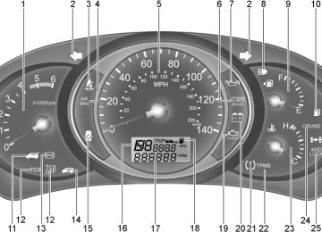
Instrument Cluster and Indicator Lights ........................................... 1-42
Instrument Panel Light Control (Rheostat) ....................................... 1-58
Interior Light ....................................................................................... 1-63Jump Starting ...................................................................................... 3-3
Keys ................................................................................................... 1-3
If you lose your keys ................................................................... 3-15
Positions ......................................................................................... 2-4Light Bulbs Replacement .................................................................. 6-26
Luggage Compartment Light ............................................................ 1-70
Luggage Net ...................................................................................... 1-74Maintenance Intervals
Explanation of scheduled maintenance items ............................... 5-7
Maintenance under severe usage conditions ............................... 5-6
Scheduled maintenance ................................................................ 5-4
Service requirements .................................................................... 5-2Mirrors
Automatic Dimming Rear View Mirror With Compass ................ 1-67
Day-night inside rearview mirror ................................................. 1-67
Outside rearview mirror ............................................................... 1-65
Outside rearview mirror Heater .................................................. 1-66Odometer / Trip Odometer ...............................................................1-50
Occupant Classification System ...................................................... 1-35Parking Brake .................................................................................... 1-69
Power Outlet ...................................................................................... 1-59
Power Steering Fluid Level ............................................................... 6-24INDEX
10
Rear Seat
Adjusting seatback angle ............................................................. 1-15
Folding rear seatback .................................................................. 1-15
Rear Window Defroster Switch ........................................................ 1-57
Reporting Safety Defects ................................................................. 8-14
Risk of Rollover ................................................................................... 2-3
Roof Rack ......................................................................................... 1-74