- 2006 GMC Canyon Owners Manuals
- GMC Canyon Owners Manuals
- 2009 GMC Canyon Owners Manuals
- GMC Canyon Owners Manuals
- 2012 GMC Canyon Owners Manuals
- GMC Canyon Owners Manuals
- 2011 GMC Canyon Owners Manuals
- GMC Canyon Owners Manuals
- 2005 GMC Canyon Owners Manuals
- GMC Canyon Owners Manuals
- 2007 GMC Canyon Owners Manuals
- GMC Canyon Owners Manuals
- 2016 GMC Canyon Owners Manuals
- GMC Canyon Owners Manuals
- 2004 GMC Canyon Owners Manuals
- GMC Canyon Owners Manuals
- 2015 GMC Canyon Owners Manuals
- GMC Canyon Owners Manuals
- 2010 GMC Canyon Owners Manuals
- GMC Canyon Owners Manuals
- 2008 GMC Canyon Owners Manuals
- GMC Canyon Owners Manuals
- Download PDF Manual
-
transmission in PARK (P) or a manual transmission in NEUTRAL before setting the parking brake. If you have a four-wheel-drive vehicle, be sure the transfer case is not in NEUTRAL (N).
If you leave your radio or other accessories
Notice: on during the jump starting procedure, they could be damaged. The repairs would not be covered by your warranty. Always turn off your radio and other accessories when jump starting your vehicle. 3. Turn off the ignition on both vehicles. Unplug
unnecessary accessories plugged into the cigarette lighter or the accessory power outlets. Turn off the radio and all lamps that are not needed. This will avoid sparks and help save both batteries. And it could save the radio!
5-41
4. Open the hoods and locate the positive (+) and
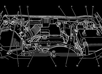
negative (−) terminal locations on the other vehicle. Your vehicle has a remote positive (+) and a remote negative (−) jump starting terminal. See Engine Compartment Overview on page 5-12
for more information on the terminal locations.{CAUTION:
Using a match near a battery can cause battery gas to explode. People have been hurt doing this, and some have been blinded. Use a flashlight if you need more light. Be sure the batteries have enough water. You do not need to add water to the ACDelco® battery (or batteries) installed in your new vehicle. But if a battery has filler caps, be sure the right amount of fluid is there. If it is low, add water to take care of that first. If you do not, explosive gas could be present. Battery fluid contains acid that can burn you. Do not get it on you. If you accidentally get it in your eyes or on your skin, flush the place with water and get medical help immediately.
5-42
{CAUTION:
Fans or other moving engine parts can injure you badly. Keep your hands away from moving parts once the engine is running.
5. Check that the jumper cables do not have loose or
missing insulation. If they do, you could get a shock. The vehicles could be damaged too. Before you connect the cables, here are some basic things you should know. Positive (+) will go to positive (+) or to a remote positive (+) terminal if the vehicle has one. Negative (−) will go to a heavy, unpainted metal engine part or to a remote negative (−) terminal if the vehicle has one. Do not connect positive (+) to negative (−) or you will get a short that would damage the battery and maybe other parts too. And do not connect the negative (−) cable to the negative (−) terminal on the dead battery because this can cause sparks.
6. Connect the red positive (+) cable to the positive (+)
terminal of the dead battery. Use a remote positive (+) terminal if the vehicle has one.
7. Do not let the other end touch metal. Connect it to the positive (+) terminal of the good battery. Use a remote positive (+) terminal if the vehicle has one.
8. Now connect the black negative (−) cable to the negative (−) terminal of the good battery. Use a remote negative (−) terminal if the vehicle has one. Do not let the other end touch anything until the next step. The other end of the negative (−) cable does not go to the dead battery. It goes to a heavy, unpainted metal engine part, or to a remote negative (−) terminal on the vehicle with the dead battery.
9. Connect the other end of the negative (−) cable at
least 18 inches (45 cm) away from the dead battery, but not near engine parts that move. The electrical connection is just as good there, and the chance of sparks getting back to the battery is much less. Your vehicle has a remote negative (−) terminal for this purpose. See Engine Compartment Overview on page 5-12 for the location of the remote negative (−) terminal.
10. Now start the vehicle with the good battery and run
the engine for a while.
11. Try to start the vehicle that had the dead battery.
If it will not start after a few tries, it probably needs service.
5-43
If the jumper cables are removed in the
Notice: wrong order, electrical shorting may occur and damage the vehicle. The repairs would not be covered by your warranty. Remove the jumper cables in the correct order, making sure that the cables do not touch each other or other metal.
Jumper Cable Removal A. Heavy, Unpainted Metal Engine Part B. Good Battery C. Dead Battery
5-44
To disconnect the jumper cables from both vehicles, do the following: 1. Disconnect the black negative (−) cable from the
vehicle that had the dead battery.
2. Disconnect the black negative (−) cable from the
vehicle with the good battery.
3. Disconnect the red positive (+) cable from the
vehicle with the good battery.
4. Disconnect the red positive (+) cable from the
other vehicle. Rear Axle When to Check and Change Lubricant It is not necessary to regularly check rear axle fluid unless you suspect there is a leak or you hear an unusual noise. A fluid loss could indicate a problem. Have it inspected and repaired. How to Check Lubricant To get an accurate reading, the vehicle should be on a level surface.
If the level is below the bottom of the filler plug hole, located on the rear axle, you will need to add some lubricant. Add enough lubricant to raise the level to the bottom of the filler plug hole. What to Use See Recommended Fluids and Lubricants on page 6-13
to determine which kind of lubricant to use. Four-Wheel Drive Lubricant checks in this section apply to this vehicle. There are two additional systems that need lubrication. Transfer Case When to Check Lubricant Refer to the Maintenance Schedule to determine how often to check the lubricant. See Additional Required Services on page 6-6.How to Check Lubricant
To get an accurate reading, the vehicle should be on a level surface. If the level is below the bottom of the filler plug hole, located on the transfer case, you’ll need to add some lubricant. Remove the plug and add enough lubricant to raise the level to the bottom of the filler plug hole. Use care not to overtighten the plug. What to Use Refer to the Maintenance Schedule to determine what kind of lubricant to use. See Recommended Fluids and Lubricants on page 6-13.
5-45
Front Axle When to Check and Change Lubricant It is not necessary to regularly check your front axle fluid unless you suspect there is a leak or you hear an unusual noise. A fluid loss could indicate a problem. Have it inspected and repaired. How to Check Lubricant
If the level is below the bottom of the filler plug hole, located on the front axle, you may need to add some lubricant. When the differential is cold, add enough lubricant to raise the level to 1/2 inch (12 mm) below the filler plug hole. When the differential is at operating temperature (warm), add enough lubricant to raise the level to the bottom of the filler plug hole. What to Use See Recommended Fluids and Lubricants on page 6-13
to determine what kind of lubricant to use.To get an accurate reading, the vehicle should be on a level surface.
5-46
Bulb Replacement For the proper types of bulbs to use, see Replacement Bulbs on page 5-51. For any bulb changing procedure not listed in this section, contact your dealer’s service department.
Headlamps Composite Headlamp System
Halogen Bulbs
{CAUTION:
Halogen bulbs have pressurized gas inside and can burst if you drop or scratch the bulb. You or others could be injured. Be sure to read and follow the instructions on the bulb package.
A. Low-Beam Headlamp B. High-Beam Headlamp
5-47
To replace the bulbs, do the following: 1. Open and support the hood. See Hood Release
on page 5-11.
2. Access the bulb/sockets from the engine
compartment.
Sealed Beam Headlamps To replace the headlamp capsule, do the following: 1. Remove the four retainer screws and the retainer. 2. Pull the headlamp capsule toward you and
unplug the electrical connector from it.
3. Remove the old headlamp capsule. 4. Plug the electrical connector into the new headlamp
capsule.
5. Reverse Steps 1 and 2 to reinstall the headlamp.
3. Turn the bulb socket counterclockwise and pull it
straight out of the headlamp housing.
4. Unplug the electrical connector from the old bulb. 5. Plug in the electrical connector to the new bulb.
Use care not to touch the new bulb with your bare hand, anything damp or oily.
6. Place the connector with the new bulb into the headlamp housing and turn it clockwise until it is tight.
5-48
Front Turn Signal, Sidemarker and Daytime Running Lamps
4. Remove the old bulb from the bulb socket. 5. Insert the new bulb into the bulb socket. 6. Insert the bulb socket into the lamp housing and
turn it clockwise until it is tight.
1. Remove the turn signal/parking lamp/daytime
running lamp (DRL) assembly by pressing on the release clip on the outboard side of the housing and pulling the outboard end of the lamp toward you.
2. Pull the inboard side of the lamp out from the small
post in the grille.
3. Turn the bulb socket counterclockwise and remove
it from the lamp housing.
7. Place the inboard end of the turn signal/parking
lamp/DRL housing over the small post in the grille.
8. Align the release clip of the lamp assembly with the
square opening in the grille.
9. Push the outboard side of the lamp assembly in,
until the release clip snaps into place.
5-49
Center High-Mounted Stoplamp (CHMSL) 1. Remove the screws and lift off the lamp assembly.
Taillamps, Turn Signal, Stoplamps and Back-up Lamps
A. Stoplamp/Taillamp B. Turn Signal C. Back-up Lamp
2. Turn the bulb socket counterclockwise and remove
it from the housing.
3. Pull the bulb straight out of the socket. 4. Insert the new bulb into the socket and press it in
until tight.
5. Insert the bulb socket into the housing and turn
until tight.
6. Reinstall the lamp assembly and tighten the screws.
1. Open the tailgate. See Tailgate on page 2-10.
5-50
2. Remove the two rear
lamp assembly screws near the tailgate latch.
3. Pull out the lamp assembly. 4. Turn the bulb socket counterclockwise to remove it
from the taillamp housing.
5. Pull the old bulb straight out from the socket. 6. Press a new bulb into the socket and turn the socket
clockwise into the taillamp housing until it is tight. 7. Reinstall the rear lamp assembly and tighten the
screws.
8. Close the tailgate.
Replacement Bulbs
Exterior Lamp
Center High-Mounted Stoplamp (CHMSL)
Headlamp
Composite High-Beam Composite Low-Beam Sealed-Beam
Parking/Front Turn Signal/Daytime Running Lamp (DRL)
Parking Lamp (Inboard)
Stoplamp, Rear Turn Signal, Taillamp, and Back-Up Lamp
Bulb Number
912
9005
9006
H60543757A
3157A
3057
For replacement bulbs not listed here, contact your dealer.
5-51
Windshield Wiper Blade Replacement Windshield wiper blades should be inspected at least twice a year for wear and cracking. See “Wiper Blade Check” under Scheduled Maintenance on page 6-4 for more information. Replacement blades come in different types and are removed in different ways. For proper type and length, see Normal Maintenance Replacement Parts on page 6-15. Notice: Allowing the wiper blade arm to touch the windshield when no wiper blade is installed could damage the windshield. Any damage that occurs would not be covered by your warranty. Do not allow the wiper blade arm to touch the windshield.
5-52
1. To remove the old wiper blades, lift the wiper arm
until it locks into a vertical position.
A. Blade Assembly B. Arm Assembly C. Locking Tab
D. Blade Pivot E. Hook Slot F. Arm Hook
2. Press down on the blade assembly pivot locking
tab. Pull down on the blade assembly to release it from the wiper arm hook.
3. Remove the insert from the blade assembly. The
insert has two notches at one end that are locked by bottom claws of the blade assembly. At the notched end, pull the insert from the blade assembly.
4. To install the new wiper insert, slide the insert (D),
notched end last, into the end with two blade claws (A). Slide the insert all the way through the blade claws at the opposite end (B). The plastic caps (C) will be forced off as the insert is fully inserted.
5. Be sure that the notches are locked by the bottom claws. Make sure that all other claws are properly locked on both sides of the insert slots.
A. Claw in Notch B. Correct Installation C. Incorrect Installation
6. Put the blade assembly pivot in the wiper arm hook.
Pull up until the pivot locking tab locks in the hook slot.
7. Carefully lower the wiper arm and blade assembly
onto the windshield.
5-53
CAUTION:
(Continued)
(cid:127) Underinflated tires pose the same danger as overloaded tires. The resulting accident could cause serious injury. Check all tires frequently to maintain the recommended pressure. Tire pressure should be checked when your tires are cold. See Inflation - Tire Pressure on page 5-60.
(cid:127) Overinflated tires are more likely to be cut, punctured or broken by a sudden impact — such as when you hit a pothole. Keep tires at the recommended pressure.
(cid:127) Worn, old tires can cause accidents.
If your tread is badly worn, or if your tires have been damaged, replace them.
Tires Your new vehicle comes with high-quality tires made by a leading tire manufacturer. If you ever have questions about your tire warranty and where to obtain service, see your GM Warranty booklet for details. For additional information refer to the tire manufacturer’s booklet included with your vehicle’s Owner’s Manual.
{CAUTION:
Poorly maintained and improperly used tires are dangerous.
(cid:127) Overloading your tires can cause
overheating as a result of too much friction. You could have an air-out and a serious accident. See Loading Your Vehicle on page 4-44.
CAUTION:
(Continued)
5-54
Tire Sidewall Labelling Useful information about a tire is molded into its sidewall. The examples below show a typical passenger vehicle tire and a compact spare tire sidewall.
Passenger Vehicle Tire Example
(A) Tire Size: The tire size is a combination of letters and numbers used to define a particular tire’s width, height, aspect ratio, construction type and service description. See the “Tire Size” illustration later in this section for more detail.
(B) TPC Spec (Tire Performance Criteria Specification): Original equipment tires designed to GM’s specific tire performance criteria have a TPC specification code molded onto the sidewall. GM’s TPC specifications meet or exceed all federal safety guidelines.
(C) DOT (Department of Transportation): The Department of Transportation (DOT) code indicates that the tire is in compliance with the U.S. Department of Transportation Motor Vehicle Safety Standards.
(D) Tire Identification Number (TIN): The letters and numbers following DOT code are the Tire Identification Number (TIN). The TIN shows the manufacturer and plant code, tire size, and date the tire was manufactured. The TIN is molded onto both sides of the tire, although only one side may have the date of manufacture.
(E) Tire Ply Material: The type of cord and number of plies in the sidewall and under the tread.
(F) Uniform Tire Quality Grading (UTQG): Tire manufacturers are required to grade tires based on three performance factors: treadwear, traction and temperature resistance. For more information see Uniform Tire Quality Grading on page 5-65.
(G) Maximum Cold Inflation Load Limit: Maximum load that can be carried and the maximum pressure needed to support that load.
5-55
(B) Tire Ply Material: The type of cord and number of plies in the sidewall and under the tread.
(C) Tire Identification Number (TIN): The Tire Identification Number (TIN). The TIN shows the manufacturer and plant code, tire size, and date the tire was manufactured. The TIN is molded onto both sides of the tire, although only one side may have the date of manufacture.
(D) Maximum Cold Inflation Load Limit: Maximum load that can be carried and the maximum pressure needed to support that load.
(E) Tire Inflation: The temporary use tire or compact spare tire should be inflated to 60 psi (420 kPa). For more information on tire pressure and inflation see Inflation - Tire Pressure on page 5-60.
(F) Tire Size: A combination of letters and numbers define a tire’s width, height, aspect ratio, construction type and service description. The letter T as the first character in the tire size means the tire is for temporary use only.
(G) TPC Spec (Tire Performance Criteria Specification): Original equipment tires designed to GM’s specific tire performance criteria have a TPC specification code molded onto the sidewall. GM’s TPC specifications meet or exceed all federal safety guidelines.
Compact Spare Tire Example
(A) Temporary Use Only: The compact spare tire or temporary use tire has a tread life of approximately 3,000 miles (5 000 km) and should not be driven at speeds over 65 mph (105 km/h). The compact spare tire is for emergency use when a regular road tire has lost air and gone flat. See “Compact Spare Tire” under Spare Tire on page 5-88 for additional information.
5-56
Tire Size The following illustration shows an example of a typical passenger vehicle tire size.
(A) P-Metric Tire: The United States version of a metric tire sizing system. The letter P as the first character in the tire size means a passenger vehicle tire engineered to standards set by the U.S. Tire and Rim Association.
(B) Tire Width: The three-digit number indicates the tire section width in millimeters from sidewall to sidewall.
(C) Aspect Ratio: A two-digit number that indicates the tire height-to-width measurements. For example, if the tire size aspect ratio is 70, as shown in item C of the illustration, it would mean that the tire’s sidewall is 70 percent as high as it is wide.
(D) Construction Code: A letter code is used to indicate the type of ply construction in the tire. The letter R means radial ply construction; the letter D means diagonal or bias ply construction; and the letter B means belted-bias ply construction.
(E) Rim Diameter: Diameter of the wheel in inches.
(F) Service Description: These characters represent the load range and speed rating of the tire. The load index represents the load carry capacity a tire is certified to carry. The load index can range from 1 to 279. The speed rating is the maximum speed a tire is certified to carry a load. Speed ratings range from A to Z.
5-57
Tire Terminology and Definitions Air Pressure: The amount of air inside the tire pressing outward on each square inch of the tire. Air pressure is expressed in pounds per square inch (psi) or kiloPascal (kPa). Accessory Weight: This means the combined weight of optional accessories. Some examples of optional accessories are, automatic transmission, power steering, power brakes, power windows, power seats, and air conditioning. Aspect Ratio: The relationship of a tire’s height to its width. Belt: A rubber coated layer of cords that is located between the plies and the tread. Cords may be made from steel or other reinforcing materials. Bead: The tire bead contains steel wires wrapped by steel cords that hold the tire onto the rim. Bias Ply Tire: A pneumatic tire in which the plies are laid at alternate angles less than 90 degrees to the centerline of the tread.
Cold Inflation Pressure: The amount of air pressure in a tire, measured in pounds per square inch (psi) or kilopascals (kPa) before a tire has built up heat from driving. See Inflation - Tire Pressure on page 5-60.
Curb Weight: This means the weight of a motor vehicle with standard and optional equipment including the maximum capacity of fuel, oil and coolant, but without passengers and cargo.
DOT Markings: A code molded into the sidewall of a tire signifying that the tire is in compliance with the U.S. Department of Transportation (DOT) motor vehicle safety standards. The DOT code includes the Tire Identification Number (TIN), an alphanumeric designator which can also identify the tire manufacturer, production plant, brand and date of production.
GVWR: Gross Vehicle Weight Rating, see Loading Your Vehicle on page 4-44.
GAWR FRT: Gross Axle Weight Rating for the front axle, see Loading Your Vehicle on page 4-44.
GAWR RR: Gross Axle Weight Rating for the rear axle, see Loading Your Vehicle on page 4-44.
Intended Outboard Sidewall: The side of an asymmetrical tire, that must always face outward when mounted on a vehicle.
KiloPascal (kPa): The metric unit for air pressure.
Light Truck (LT-Metric) Tire: A tire used on light duty trucks and some multipurpose passenger vehicles.
5-58
Load Index: An assigned number ranging from 1 to 279 that corresponds to the load carrying capacity of a tire.
Passenger (P-Metric) Tire: A tire used on passenger cars and some light duty trucks and multipurpose vehicles.
Maximum Inflation Pressure: The maximum air pressure to which a cold tire may be inflated. The maximum air pressure is molded onto the sidewall.
Maximum Load Rating: The load rating for a tire at the maximum permissible inflation pressure for that tire.
Maximum Loaded Vehicle Weight: The sum of curb weight; accessory weight; vehicle capacity weight; and production options weight.
Normal Occupant Weight: The number of occupants a vehicle is designed to seat multiplied by 150 lbs (68 kg). See Loading Your Vehicle on page 4-44.
Occupant Distribution: Designated seating positions.
Outward Facing Sidewall: The side of an asymmetrical tire that has a particular side that faces outward when mounted on a vehicle. The side of the tire that contains a whitewall, bears white lettering or bears manufacturer, brand, and/or model name molding that is higher or deeper than the same moldings on the other sidewall of the tire.
Recommended Inflation Pressure: Vehicle manufacturer’s recommended tire inflation pressure and shown on the tire placard. See Inflation - Tire Pressure on page 5-60 and Loading Your Vehicle on page 4-44.
Radial Ply Tire: A pneumatic tire in which the ply cords that extend to the beads are laid at 90 degrees to the centerline of the tread.
Rim: A metal support for a tire and upon which the tire beads are seated.
Sidewall: The portion of a tire between the tread and the bead.
Speed Rating: An alphanumeric code assigned to a tire indicating the maximum speed at which a tire can operate.
Traction: The friction between the tire and the road surface. The amount of grip provided.
Tread: The portion of a tire that comes into contact with the road.
5-59
Treadwear Indicators: Narrow bands, sometimes called “wear bars,” that show across the tread of a tire when only 1/16 inch (1.6 mm) of tread remains. See When It Is Time for New Tires on page 5-63.
UTQGS (Uniform Tire Quality Grading Standards): A tire information system that provides consumers with ratings for a tire’s traction, temperature, and treadwear. Ratings are determined by tire manufacturers using government testing procedures. The ratings are molded into the sidewall of the tire. See Uniform Tire Quality Grading on page 5-65.
Vehicle Capacity Weight: The number of designated seating positions multiplied by 150 lbs (68 kg) plus the rated cargo load. See Loading Your Vehicle on page 4-44.
Vehicle Maximum Load on the Tire: Load on an individual tire due to curb weight, accessory weight, occupant weight, and cargo weight.
Vehicle Placard: A label permanently attached to a vehicle showing the vehicle’s capacity weight and the original equipment tire size and recommended inflation pressure. See “Tire and Loading Information Label” under Loading Your Vehicle on page 4-44.
Inflation - Tire Pressure Tires need the correct amount of air pressure to operate effectively. Notice: Do not let anyone tell you that under-inflation or over-inflation is all right. It is not. If your tires do not have enough air (under-inflation), you can get the following:
Too much flexing Too much heat Tire overloading
(cid:127) Premature or irregular wear (cid:127) Poor handling (cid:127) Reduced fuel economy If your tires have too much air (over-inflation), you can get the following: (cid:127) Unusual wear (cid:127) Poor handling (cid:127) Rough ride (cid:127) Needless damage from road hazards
5-60
(cid:127) (cid:127) (cid:127) A Tire and Loading Information label is attached to the vehicle’s center pillar (B-pillar), below the driver’s door latch. This label shows your vehicle’s original equipment tires and the correct inflation pressures for your tires when they are cold. The recommended cold tire inflation pressure, shown on the label, is the minimum amount of air pressure needed to support your vehicle’s maximum load carrying capacity. For additional information regarding how much weight your vehicle can carry, and an example of the tire and loading information label, see Loading Your Vehicle on page 4-44. How you load your vehicle affects vehicle handling and ride comfort, never load your vehicle with more weight than it was designed to carry. When to Check Check your tires once a month or more. Also check the tire pressure of the spare tire. If you have a compact spare tire, it should be at 60 psi (420 kPa). See Spare Tire on page 5-88 for additional information.
How to Check Use a good quality pocket-type gage to check tire pressure. You cannot tell if your tires are properly inflated simply by looking at them. Radial tires may look properly inflated even when they are underinflated. Check the tire’s inflation pressure when the tires are cold. Cold means your vehicle has been sitting for at least three hours or driven no more than 1 mile (1.6 km). Remove the valve cap from the tire valve stem. Press the tire gage firmly onto the valve to get a pressure measurement. If the cold tire inflation pressure matches the recommended pressure on the Tire and Loading Information label, no further adjustment is necessary. If the inflation pressure is low, add air until you reach the recommended amount. If you overfill the tire, release air by pushing on the metal stem in the center of the tire valve. Recheck the tire pressure with the tire gage. Be sure to put the valve caps back on the valve stems. They help prevent leaks by keeping out dirt and moisture.
5-61
Tire Inspection and Rotation Tires should be rotated every 5,000 to 8,000 miles (8 000 to 13 000 km). Any time you notice unusual wear, rotate your tires as soon as possible and check wheel alignment. Also check for damaged tires or wheels. See When It Is Time for New Tires on page 5-63 and Wheel Replacement on page 5-66 for more information. Make sure the spare tire is stored securely. Push, pull, and then try to rotate or turn the tire. If it moves, use the wheel wrench to tighten the cable. See Changing a Flat Tire on page 5-70. The purpose of regular rotation is to achieve more uniform wear for all tires on the vehicle. The first rotation is the most important, see Scheduled Maintenance on page 6-4.
When rotating your tires, always use one of the correct rotation patterns shown here. If your vehicle has a compact spare tire or a spare tire that does not match your vehicle’s road tires and wheels, in size and type, do not include the spare in the tire rotation.
5-62
After the tires have been rotated, adjust the front and rear inflation pressures as shown on the Tire and Loading Information label. For the location of the tire and loading information label see Loading Your Vehicle on page 4-44. Make certain that all wheel nuts are properly tightened, see “Wheel Nut Torque” under Capacities and Specifications on page 5-103 for the proper wheel nut torque specification.
{CAUTION:
Rust or dirt on a wheel, or on the parts to which it is fastened, can make wheel nuts become loose after a time. The wheel could come off and cause an accident. When you change a wheel, remove any rust or dirt from places where the wheel attaches to the vehicle. In an emergency, you can use a cloth or a paper towel to do this; but be sure to use a scraper or wire brush later, if you need to, to get all the rust or dirt off. See Changing a Flat Tire on page 5-70.
When It Is Time for New Tires
One way to tell when it’s time for new tires is to check the treadwear indicators, which will appear when your tires have only 1/16 inch (1.6 mm) or less of tread remaining. Some commercial truck tires may not have treadwear indicators.
You need a new tire if any of the following statements are true: (cid:127) You can see the indicators at three or more places
around the tire.
(cid:127) You can see cord or fabric showing through the
tire’s rubber. The tread or sidewall is cracked, cut or snagged deep enough to show cord or fabric. The tire has a bump, bulge or split. The tire has a puncture, cut or other damage that can’t be repaired well because of the size or location of the damage.
5-63
(cid:127) (cid:127) (cid:127) Buying New Tires To find out what kind and size of tires you need, look at the Tire and Loading Information label. For more information about this label and its location on your vehicle, See Loading Your Vehicle on page 4-44. The tires installed on your vehicle when it was new had a Tire Performance Criteria Specification (TPC Spec) number on each tire’s sidewall. When you get new tires, GM recommends that you get tires with that same TPC Spec number. That way your vehicle will continue to have tires that are designed to give proper endurance, handling, speed rating, traction, ride and other things during normal service on your vehicle. If your tires have an all-season tread design, the TPC number will be followed by an “MS” (for mud and snow). If you ever replace your tires with those not having a TPC Spec number, make sure they are the same size, load range, speed rating and construction type (bias, bias-belted or radial) as your original tires.
{CAUTION:
Mixing tires could cause you to lose control while driving. If you mix tires of different sizes or types (radial and bias-belted tires), the vehicle may not handle properly, and you could have a crash. Using tires of different sizes may also cause damage to your vehicle. Be sure to use the same size and type tires on all wheels. It’s all right to drive with your compact spare (if you have one). It was developed for use on your vehicle.
{CAUTION:
If you use bias-ply tires on your vehicle, the wheel rim flanges could develop cracks after many miles of driving. A tire and/or wheel could fail suddenly, causing a crash. Use only radial-ply tires with the wheels on your vehicle.
5-64
Uniform Tire Quality Grading Quality grades can be found where applicable on the tire sidewall between tread shoulder and maximum section width. For example: Treadwear 200 Traction AA Temperature A The following information relates to the system developed by the United States National Highway Traffic Safety Administration, which grades tires by treadwear, traction and temperature performance. (This applies only to vehicles sold in the United States.) The grades are molded on the sidewalls of most passenger car tires. The Uniform Tire Quality Grading system does not apply to deep tread, winter-type snow tires, space-saver or temporary use spare tires, tires with nominal rim diameters of 10 to 12 inches (25 to 30 cm), or to some limited-production tires. While the tires available on General Motors passenger cars and light trucks may vary with respect to these grades, they must also conform to federal safety requirements and additional General Motors Tire Performance Criteria (TPC) standards.
Treadwear The treadwear grade is a comparative rating based on the wear rate of the tire when tested under controlled conditions on a specified government test course. For example, a tire graded 150 would wear one and a half (1.5) times as well on the government course as a tire graded 100. The relative performance of tires depends upon the actual conditions of their use, however, and may depart significantly from the norm due to variations in driving habits, service practices and differences in road characteristics and climate. Traction – AA, A, B, C The traction grades, from highest to lowest, are AA, A, B, and C. Those grades represent the tire’s ability to stop on wet pavement as measured under controlled conditions on specified government test surfaces of asphalt and concrete. A tire marked C may have poor traction performance. Warning: The traction grade assigned to this tire is based on straight-ahead braking traction tests, and does not include acceleration, cornering, hydroplaning, or peak traction characteristics.
5-65
Temperature – A, B, C The temperature grades are A (the highest), B, and C, representing the tire’s resistance to the generation of heat and its ability to dissipate heat when tested under controlled conditions on a specified indoor laboratory test wheel. Sustained high temperature can cause the material of the tire to degenerate and reduce tire life, and excessive temperature can lead to sudden tire failure. The grade C corresponds to a level of performance which all passenger car tires must meet under the Federal Motor Vehicle Safety Standard No. 109. Grades B and A represent higher levels of performance on the laboratory test wheel than the minimum required by law. Warning: The temperature grade for this tire is established for a tire that is properly inflated and not overloaded. Excessive speed, underinflation, or excessive loading, either separately or in combination, can cause heat buildup and possible tire failure.
Wheel Alignment and Tire Balance The wheels on your vehicle were aligned and balanced carefully at the factory to give you the longest tire life and best overall performance. If you notice unusual tire wear or your vehicle pulling one way or the other, the alignment may need to be reset. If you notice your vehicle vibrating when driving on a smooth road, your wheels may need to be rebalanced.
Wheel Replacement Replace any wheel that is bent, cracked or badly rusted or corroded. If wheel nuts keep coming loose, the wheel, wheel bolts and wheel nuts should be replaced. If the wheel leaks air, replace it (except some aluminum wheels, which can sometimes be repaired). See your dealer if any of these conditions exist. Your dealer will know the kind of wheel you need.
5-66
Each new wheel should have the same load-carrying capacity, diameter, width, offset and be mounted the same way as the one it replaces. If you need to replace any of your wheels, wheel bolts or wheel nuts, replace them only with new GM original equipment parts. This way, you will be sure to have the right wheel, wheel bolts and wheel nuts for your vehicle.
Notice: The wrong wheel can also cause problems with bearing life, brake cooling, speedometer or odometer calibration, headlamp aim, bumper height, vehicle ground clearance and tire or tire chain clearance to the body and chassis. See Changing a Flat Tire on page 5-70 for more information. Used Replacement Wheels
{CAUTION:
Using the wrong replacement wheels, wheel bolts or wheel nuts on your vehicle can be dangerous. It could affect the braking and handling of your vehicle, make your tires lose air and make you lose control. You could have a collision in which you or others could be injured. Always use the correct wheel, wheel bolts and wheel nuts for replacement.
{CAUTION:
Putting a used wheel on your vehicle is dangerous. You can’t know how it’s been used or how far it’s been driven. It could fail suddenly and cause a crash. If you have to replace a wheel, use a new GM original equipment wheel.
5-67
If your vehicle has a tire size other than
Notice: P225/75R15 or P265/75R15 use tire chains only where legal and only when you must. Use chains that are the proper size for your tires. Install them on the tires of the rear axle. Do not use chains on the tires of the front axle. Tighten them as tightly as possible with the ends securely fastened. Drive slowly and follow the chain manufacturer’s instructions. If you can hear the chains contacting your vehicle, stop and retighten them. If the contact continues, slow down until it stops. Driving too fast or spinning the wheels with chains on will damage your vehicle.
Tire Chains
{CAUTION:
If your vehicle has P225/75R15 or P265/75R15
size tires, do not use tire chains. They can damage your vehicle because there is not enough clearance. Tire chains used on a vehicle without the proper amount of clearance can cause damage to the brakes, suspension or other vehicle parts. The area damaged by the tire chains could cause you to lose control of your vehicle and you or others may be injured in a crash. Use another type of traction device only if its manufacturer recommends it for use on your vehicle and tire size combination and road conditions. Follow that manufacturer’s instructions. To help avoid damage to your vehicle, drive slowly, readjust or remove the device if it is contacting your vehicle, and do not spin your wheels. If you do find traction devices that will fit, install them on the rear tires.5-68
If a Tire Goes Flat It’s unusual for a tire to “blowout” while you’re driving, especially if you maintain your tires properly. If air goes out of a tire, it’s much more likely to leak out slowly. But if you should ever have a “blowout,” here are a few tips about what to expect and what to do: If a front tire fails, the flat tire will create a drag that pulls the vehicle toward that side. Take your foot off the accelerator pedal and grip the steering wheel firmly. Steer to maintain lane position, and then gently brake to a stop well out of the traffic lane. A rear blowout, particularly on a curve, acts much like a skid and may require the same correction you’d use in a skid. In any rear blowout, remove your foot from the accelerator pedal. Get the vehicle under control by steering the way you want the vehicle to go. It may be very bumpy and noisy, but you can still steer. Gently brake to a stop, well off the road if possible.
{CAUTION:
Lifting a vehicle and getting under it to do maintenance or repairs is dangerous without the appropriate safety equipment and training. The jack provided with your vehicle is designed only for changing a flat tire. If it is used for anything else, you or others could be badly injured or killed if the vehicle slips off the jack. Use the jack provided with your vehicle only for changing a flat tire.
If a tire goes flat, the next part shows how to use your jacking equipment to change a flat tire safely.
5-69
Changing a Flat Tire If a tire goes flat, avoid further tire and wheel damage by driving slowly to a level place. Turn on your hazard warning flashers.
{CAUTION:
Changing a tire can be dangerous. The vehicle can slip off the jack and roll over or fall on you or other people. You and they could be badly injured or even killed. Find a level place to change your tire. To help prevent the vehicle from moving:
1. Set the parking brake firmly. 2. Put an automatic transmission shift lever in PARK (P), or shift a manual transmission to FIRST (1) or REVERSE (R).
3. If you have a four-wheel-drive vehicle, be sure the transfer case is in a drive gear — not in NEUTRAL.
4. Turn off the engine and do not restart while
the vehicle is raised.
5. Do not allow passengers to remain in
the vehicle.
CAUTION:
(Continued)
5-70
CAUTION:
(Continued)
To be even more certain the vehicle won’t move, you can put blocks at the front and rear of the tire farthest away from the one being changed. That would be the tire on the other side, at the opposite end of the vehicle.
When you have a flat tire, use the following as a guide to assist you in the placement of the wheel blocks.
The following information will tell you next how to use the jack and change a tire.
Removing the Spare Tire and Tools The tools you will need are located under the passenger’s seat.
For regular and extended cab vehicles, the jack and wheel blocks are located under the cover at the center of the vehicle behind the front seats.
Crew Cab
For crew cab models, the jack and wheel blocks are under the driver’s side rear seat.
Regular/Extended Cab
The vehicle will have a cover if it is an extended or regular cab.
1. Move the seats forward
to access the cover.
5-71
2. Turn the wing nut on the cover counterclockwise to
remove it. For crew cab models, reach under the rear seat to access the jack and wheel blocks. To reinstall the jack and wheel block assembly in the mounting bracket, insert the tabs into the jack base by pushing the blocks up into the assembly. The outer hole in the jack base aligns with the tab on the bracket. When reinstalling, make sure the jack is secure, but do not overtighten the jack in the bracket.
3. Remove the wheel blocks and the wheel block
retainer by turning the wing nut counterclockwise.
4. Put the wheel blocks at the front and rear of the tire
farthest away from the one being changed. That would be the tire on the other side, at the opposite end of the vehicle.
5. Locate the wing nut used to retain the storage bag and tools which is under the front passenger’s seat. Remove it by turning the wing nut counterclockwise.
5-72
You will use the jack handle extensions and the wheel wrench to remove the underbody-mounted spare tire.
A. Jack Handle
Extensions B. Bottle Jack
C. Extension Tool D. Wheel Wrench E. Wheel Blocks
1. Assemble the wheel wrench (D) and the jack
handle extensions (A) as shown.
4. Tilt the retainer when
the tire has been lowered, and slide it up the cable so it can be pulled up through the wheel opening.
5. Put the spare tire near the flat tire.
5-73
2. Insert the hoist end (chiseled end) of the extension
tool (C) through the hole in the rear bumper and into the funnel-shaped guide. The chiseled end of the extension is used to lower the spare tire.
3. Turn the wheel wrench (D) counterclockwise to lower the spare tire to the ground. Continue to turn the wheel wrench until the spare tire can be pulled out from under the vehicle. If the spare tire does not lower to the ground, the secondary latch is engaged causing the tire not to lower. See Secondary Latch System on page 5-81.
Removing the Flat Tire and Installing the Spare Tire Use the following pictures and instructions to remove the flat tire and raise the vehicle.
The tools you will be using include the bottle jack (A), the wheel blocks (B), the extension tool (C), the jack handle extensions (D), and the wheel wrench (E).
5-74
1. Remove the center cap by placing the chisel end of
the wheel wrench (E) in the slot on the wheel and gently prying the cap out. If your vehicle has the Xtreme package, remove each wheel nut cap with the wheel wrench and remove the center cap by hand.
2. Use the wheel wrench to loosen all the wheel nuts by turning it counterclockwise. Do not remove the wheel nuts yet.
{CAUTION:
Getting under a vehicle when it is jacked up is dangerous. If the vehicle slips off the jack you could be badly injured or killed. Never get under a vehicle when it is supported only by a jack.
{CAUTION:
Raising your vehicle with the jack improperly positioned can damage the vehicle and even make the vehicle fall. To help avoid personal injury and vehicle damage, be sure to fit the jack lift head into the proper location before raising the vehicle.
5-75
Front Position
Front Position
3. Position the jack (A) under the vehicle as shown for
the front or rear locations.
If the flat tire is on the front of the vehicle, position the jack to the rear of the front tire in the pocket off of the frame.
5-76
Rear Position
If the flat tire is on the rear, position the jack under the rear axle and get as close as possible to the shock absorber.
4. Make sure the jack head is positioned so that the rear axle is resting securely between the grooves that are on the jack head.
5. Turn the wheel wrench clockwise to raise the
vehicle. Raise the vehicle far enough off the ground so there is enough room for the spare tire to fit under the wheel well.
6. Remove all the wheel nuts and take off the flat tire.
5-77
{CAUTION:
Rust or dirt on the wheel, or on the parts to which it is fastened, can make the wheel nuts become loose after a time. The wheel could come off and cause an accident. When you change a wheel, remove any rust or dirt from the places where the wheel attaches to the vehicle. In an emergency, you can use a cloth or a paper towel to do this; but be sure to use a scraper or wire brush later, if you need to, to get all the rust or dirt off.
7. Remove any rust or dirt
from the wheel bolts, mounting surfaces and spare wheel.
8. Place the spare tire on the mounting surface.
{CAUTION:
Never use oil or grease on studs or nuts. If you do, the nuts might come loose. Your wheel could fall off, causing a serious accident.
9. Put the wheel nuts
back on with the rounded end of the nuts toward the wheel. Tighten each wheel nut by hand. Then use the wheel wrench to tighten the nuts until the wheel is held against the hub.
5-78
Front Position
Rear Position
10. Turn the wheel wrench counterclockwise to lower
the vehicle. Lower the jack completely.
5-79
11. Tighten the wheel nuts
firmly in a crisscross sequence as shown by turning the wheel wrench clockwise.
When you reinstall the regular wheel and tire, you must also reinstall the center cap. Place the cap on the wheel and tap it into place until it seats flush with the wheel. The cap only goes on one way. Be sure to line up the tab on the center cap with the indentation on the wheel. For the Xtreme, tighten each nut cap by hand, then tighten an additional one quarter of a turn with the wheel wrench.
{CAUTION:
Incorrect wheel nuts or improperly tightened wheel nuts can cause the wheel to come loose and even come off. This could lead to an accident. Be sure to use the correct wheel nuts. If you have to replace them, be sure to get new GM original equipment wheel nuts. Stop somewhere as soon as you can and have the nuts tightened with a torque wrench to the proper torque specification. See Capacities and Specifications on page 5-103 for wheel nut torque specification.
Improperly tightened wheel nuts can lead
Notice: to brake pulsation and rotor damage. To avoid expensive brake repairs, evenly tighten the wheel nuts in the proper sequence and to the proper torque specification. See Capacities and Specifications on page 5-103 for the wheel nut torque specification.
5-80
Secondary Latch System Your vehicle has an underbody-mounted tire hoist assembly equipped with a secondary latch system. It is designed to stop the spare tire from suddenly falling off your vehicle. For the secondary latch to work, the spare must be installed with the valve stem pointing down. See Storing a Flat or Spare Tire and Tools on page 5-84.
{CAUTION:
Before beginning this procedure read all the instructions. Failure to read and follow the instructions could damage the hoist assembly and you and others could get hurt. Read and follow the instructions listed below.
To release the spare tire from the secondary latch, do the following:
1. Check under the vehicle to see if the cable end
fitting is visible.
2. If the cable end fitting is not visible, proceed to
Step 6. If it is visible, first try to tighten the cable by turning the wheel wrench clockwise until you hear two clicks or feel it skip twice. You cannot overtighten the cable.
3. Loosen the cable by turning the wheel wrench
counterclockwise three or four turns.
5-81
4. Repeat this procedure at least two times. If the
spare tire lowers to the ground, continue with Step 5 under Removing the Spare Tire and Tools on page 5-71.
5. Turn the wrench counterclockwise until
approximately 6 inches (15 cm) of cable is exposed.
6. Stand the wheel blocks on their shortest ends, with the backs facing each other.
7. Place the bottom edge of the jack on the wheel
blocks, separating them so that the jack is balanced securely.
5-82
8. Attach the jack handle, extension, and wheel
wrench to the jack and place it (with the wheel blocks) under the vehicle towards the front of the rear bumper. Position the center lift point of the jack under the wheel.
9. Turn the wrench clockwise to raise the jack until it
lifts the tire.
10. Continue raising the jack until the tire stops moving
upward and is held firmly in place, the secondary latch has released and the tire is balancing on the jack.
11. Remove the jack handle and insert the hoist end of the extension through the hole in the rear bumper. Turn the wheel counterclockwise one turn or until the wheel retainer assembly falls out.
12. Reinsert the jack handle into the jack. Lower the
jack by turning the wheel wrench counterclockwise. Keep lowering the jack until the spare tire slides off the jack or is hanging by the cable.
{CAUTION:
Someone standing too close during the procedure could be injured by the jack. If the spare tire does not slide off the jack completely, make sure no one is behind you or on either side of you as you pull the jack out from the spare.
13. Disconnect the jack handle from the jack and
carefully remove the jack. Use one hand to push against the spare while firmly pulling the jack out from under the spare tire with the other hand. If the spare tire is hanging from the cable, insert the hoist handle, extension and wheel wrench into the hoist shaft hole in the bumper and turn the wheel wrench counterclockwise to lower the spare the rest of the way.
5-83
Storing a Flat or Spare Tire and Tools
{CAUTION:
Storing a jack, a tire, or other equipment in the passenger compartment of the vehicle could cause injury. In a sudden stop or collision, loose equipment could strike someone. Store all these in the proper place.
Notice: Storing an aluminum wheel with a flat tire under your vehicle for an extended period of time or with the valve stem pointing up may damage the wheel. Always stow the wheel with the valve stem pointing down and have the wheel/tire repaired as soon as possible.
14. Tilt the tire retainer at the end of the cable and pull it through the wheel opening. Pull the tire out from under the vehicle.
15. If the cable is hanging under the vehicle, turn the
wheel wrench clockwise to raise the cable back up. Have the hoist assembly inspected as soon as you can. You will not be able to store a spare or flat tire using the hoist assembly until it has been replaced. To continue changing the flat tire, see Removing the Flat Tire and Installing the Spare Tire on page 5-74.
5-84
Store the tire under the rear of the vehicle in the spare tire carrier. Use the art and text following to help you. 1. Put the tire on the ground at the rear of the vehicle
with the valve stem pointed down.
2. Tilt the retainer downward and through the wheel
opening. Make sure the retainer is fully seated across the underside of the wheel.
3. Attach the wheel wrench and extensions together.
5-85
4. Insert the hoist end through the hole in the rear
bumper and into the funnel-shaped guide.
5. Turn the wheel wrench clockwise to raise the
tire part way up. Make sure the retainer is seated in the wheel opening and the valve stem is pointed down.
6. Raise the tire fully against the underside of the vehicle by turning the wheel wrench clockwise until you feel it skip twice. You cannot overtighten the cable.
5-86
7. Make sure the tire is stored securely. Push, pull (A),
and then try to turn (B) the tire. If the tire moves, check to make sure the tire valve stem is pointing down, then use the wheel wrench to loosen and then tighten the cable.
To store the tools, do the following: 1. Return the wheel wrench, jack extensions and the
storage bag to the locations described under Removing the Spare Tire and Tools on page 5-71.
2. Reinstall the jack and wheel blocks, be sure
to install the wheel blocks first.
3. Secure the items in the vehicle as shown next.
A. Bottle Jack B. Wheel Blocks C. Wing Nut
Regular/Extended Cab
Crew Cab
A. Bottle Jack B. Wheel Blocks C. Wing Nut
5-87
Spare Tire Compact Spare Tire Your vehicle may be equipped with a compact spare tire. Although the compact spare tire was fully inflated when your vehicle was new, it can lose air after a time. Check the inflation pressure regularly. It should be 60 psi (420 kPa). After installing the compact spare on your vehicle, you should stop as soon as possible and make sure your spare tire is correctly inflated. The compact spare is made to perform well at speeds up to 65 mph (105 km/h) for distances up to 3,000 miles (5 000 km), so you can finish your trip and have your full-size tire repaired or replaced where you want. For heavy payloads or towing, and for low traction or four-wheel-drive conditions, repair or replace the full-size tire, and reinstall for best performance. Of course, it’s best to replace your spare with a full-size tire as soon as you can. Your spare will last longer and be in good shape in case you need it again. Notice: When the compact spare is installed, do not take your vehicle through an automatic car wash with guide rails. The compact spare can get caught on the rails. That can damage the tire and wheel, and maybe other parts of your vehicle. Don’t use your compact spare on other vehicles.
5-88
And don’t mix your compact spare tire or wheel with other wheels or tires. They won’t fit. Keep your spare tire and its wheel together. Notice: Tire chains will not fit your compact spare. Using them can damage your vehicle and can damage the chains too. Do not use tire chains on your compact spare. Full-Size Spare Tire Your vehicle may be equipped with a full-size spare tire, which, when new, was fully inflated. A spare tire, whether compact-size or full-size, may lose air over time, so check its inflation pressure regularly. See Inflation - Tire Pressure on page 5-60 and Loading Your Vehicle on page 4-44 for information regarding proper tire inflation and loading your vehicle. For instruction on how to remove, install or store a spare tire, see Changing a Flat Tire on page 5-70. After installing the spare tire on your vehicle, you should stop as soon as possible and make sure the spare is correctly inflated. Have the damaged or flat road tire repaired or replaced as soon as you can and installed back onto your vehicle. This way, a spare tire will be available in case you need it again. Don’t mix tires and wheels of different sizes, because they won’t fit. Keep your spare tire and its wheel together.
Appearance Care Cleaning products can be hazardous. Some are toxic. Other cleaning products can burst into flames if a match is struck near them or if they get on a hot part of the vehicle. Some are dangerous if their fumes are inhaled in a closed space. When anything from a container is used to clean the vehicle, be sure to follow the manufacturer’s warnings and instructions. Always open the doors or windows of the vehicle when cleaning the inside. Never use these to clean the vehicle: (cid:127) Gasoline (cid:127) Benzene (cid:127) Naphtha (cid:127) Carbon Tetrachloride (cid:127) Acetone (cid:127) Paint Thinner
Turpentine Lacquer Thinner
(cid:127) Nail Polish Remover They can all be hazardous — some more than others — and they can all damage the vehicle, too.
Do not use any of these products unless this manual says you can. In many uses, these will damage the vehicle: (cid:127) Alcohol
Laundry Soap
(cid:127) Bleach (cid:127) Reducing Agents
Fabric/Carpet Use a vacuum cleaner often to get rid of dust and loose dirt. Wipe vinyl, leather, plastic, and painted surfaces with a clean, damp cloth. GM-approved cleaning products can be obtained from your dealer. Here are some cleaning tips: (cid:127) Always read the instructions on the cleaner label. (cid:127) Clean up stains as soon as you can before they set. (cid:127) Carefully scrape off any excess stain. (cid:127) Use a clean cloth or sponge, and change to a clean
area often. A soft brush may be used if stains are stubborn. To avoid forming a ring on fabric after spot cleaning, clean the entire area immediately or it will set.
5-89
(cid:127) (cid:127) (cid:127) (cid:127) Most stains can be removed with club soda water. To clean, use the following instructions: 1. For liquids: blot with a clean, soft, white cloth.
For solids: remove as much as possible and then vacuum or brush.
2. Apply club soda water to a clean, soft, white cloth.
Do not over-saturate; the cloth should not drip water.
3. Clean the entire area. Avoid getting the fabric
too wet.
4. Start cleaning from the seams into the stain to
avoid a ring effect.
5. Continue cleaning, using a clean area of the cloth
each time it becomes soiled.
6. When the stain is removed, blot the cleaned area
with another dry, clean, soft, white cloth.
Using Cleaner on Fabric 1. First, try the cleaner on an area of the fabric that is not easily seen to make sure the cleaner does not affect the color of the fabric.
2. For liquids: blot with a clean, soft, white cloth.
For solids: remove as much as possible and then vacuum or brush.
3. Spray a small amount of the cleaner onto a clean
soft, white, cloth. Do not apply spray directly to the fabric.
4. Start cleaning from the seams into the stain to
avoid a ring effect.
5. Continue cleaning, using a clean area of the cloth
each time it becomes soiled.
6. When the stain is removed, blot the cleaned area
with another dry, clean, soft, white cloth.
7. If the cleaner leaves a ring effect, follow up with the club soda water instructions given earlier in this section.
5-90
Special Fabric Cleaning Problems Stains caused by such things as catsup, black coffee, egg, fruit, fruit juice, milk, soft drinks, vomit, urine, and blood can be removed using the club soda water instructions given earlier in this section. If an odor lingers after cleaning vomit or urine, treat the area with a water and baking soda solution: 1 teaspoon (5 ml) of baking soda to 1 cup (250 ml) of lukewarm water. Let dry. Stains caused by oil and grease can be cleaned with an approved GM cleaner and a clean, white cloth. 1. Carefully scrape off excess stain. 2. Clean with cool water and allow to dry completely. 3. If a stain remains, follow the “Using Cleaner on
Fabric” instructions described earlier.
Vinyl Use warm water and a clean cloth. (cid:127) Rub with a clean, damp cloth to remove dirt. This may have to be done more than once. Things like tar, asphalt, and shoe polish will stain if they are not removed quickly. Use a clean cloth and vinyl cleaner. See your dealer for this product.
Leather Use a soft cloth with lukewarm water and a mild soap or saddle soap and wipe dry with a soft cloth. Then, let the leather dry naturally. Do not use heat to dry.
For stubborn stains, use a leather cleaner.
(cid:127) Never use oils, varnishes, solvent-based or abrasive cleaners, furniture polish, or shoe polish on leather.
(cid:127) Soiled or stained leather should be cleaned
immediately. If dirt is allowed to work into the finish, it can harm the leather.
5-91
(cid:127) (cid:127) Instrument Panel Use only mild soap and water to clean the top surfaces of the instrument panel. Sprays containing silicones or waxes may cause annoying reflections in the windshield and even make it difficult to see through the windshield under certain conditions.
Interior Plastic Components Use only a mild soap and water solution on a soft cloth or sponge. Commercial cleaners may affect the surface finish.
Glass Surfaces Glass should be cleaned often. GM Glass Cleaner or a liquid household glass cleaner will remove normal tobacco smoke and dust films on interior glass. See Vehicle Care/Appearance Materials on page 5-97. Notice: cleaning glass surfaces on your vehicle, you could scratch the glass. When cleaning the glass on your vehicle, use only a soft cloth and glass cleaner.
If you use abrasive cleaners when
Care of Safety Belts Keep belts clean and dry.
{CAUTION:
Do not bleach or dye safety belts. If you do, it may severely weaken them. In a crash, they might not be able to provide adequate protection. Clean safety belts only with mild soap and lukewarm water.
Weatherstrips Silicone grease on weatherstrips will make them last longer, seal better, and not stick or squeak. Apply silicone grease with a clean cloth. During very cold, damp weather frequent application may be required. See Recommended Fluids and Lubricants on page 6-13.
5-92
Washing Your Vehicle The paint finish on the vehicle provides beauty, depth of color, gloss retention, and durability. The best way to preserve the vehicle’s finish is to keep it clean by washing it often with lukewarm or cold water. Do not wash the vehicle in the direct rays of the sun. Use a car washing soap. Do not use strong soaps or chemical detergents. Be sure to rinse the vehicle well, removing all soap residue completely. GM-approved cleaning products can be obtained from your dealer. See Vehicle Care/Appearance Materials on page 5-97. Do not use cleaning agents that are petroleum based, or that contain acid or abrasives. All cleaning agents should be flushed promptly and not allowed to dry on the surface, or they could stain. Dry the finish with a soft, clean chamois or an all-cotton towel to avoid surface scratches and water spotting. Notice: automatic car wash that does not have enough clearance for the wide rear tires and wheels, you could damage your vehicle. Verify with the manager of the car wash that your vehicle will fit before entering the car wash or use a touchless car wash. High pressure car washes may cause water to enter the vehicle.
If you drive your vehicle through an
Cleaning Exterior Lamps/Lenses Use only lukewarm or cold water, a soft cloth and a car washing soap to clean exterior lamps and lenses. Follow instructions under Washing Your Vehicle on page 5-93.
Finish Care Occasional waxing or mild polishing of your vehicle by hand may be necessary to remove residue from the paint finish. You can get GM-approved cleaning products from your dealer. See Vehicle Care/Appearance Materials on page 5-97. If your vehicle has a “basecoat/clearcoat” paint finish. The clearcoat gives more depth and gloss to the colored basecoat. Always use waxes and polishes that are non-abrasive and made for a basecoat/clearcoat paint finish. Notice: Machine compounding or aggressive polishing on a basecoat/clearcoat paint finish may damage it. Use only non-abrasive waxes and polishes that are made for a basecoat/clearcoat paint finish on your vehicle.
5-93
Windshield and Wiper Blades If the windshield is not clear after using the windshield washer, or if the wiper blade chatters when running, wax, sap, or other material may be on the blade or windshield. Clean the outside of the windshield with a glass cleaning liquid or powder and water solution. The windshield is clean if beads do not form when it is rinsed with water. Grime from the windshield will stick to the wiper blades and affect their performance. Clean the blade by wiping vigorously with a cloth soaked in full-strength windshield washer solvent. Then rinse the blade with water. Check the wiper blades and clean them as necessary; replace blades that look worn.
Foreign materials such as calcium chloride and other salts, ice melting agents, road oil and tar, tree sap, bird droppings, chemicals from industrial chimneys, etc., can damage your vehicle’s finish if they remain on painted surfaces. Wash the vehicle as soon as possible. If necessary, use non-abrasive cleaners that are marked safe for painted surfaces to remove foreign matter. Exterior painted surfaces are subject to aging, weather and chemical fallout that can take their toll over a period of years. You can help to keep the paint finish looking new by keeping your vehicle garaged or covered whenever possible. Protecting Exterior Bright Metal Parts Bright metal parts should be cleaned regularly to keep their luster. Washing with water is all that is usually needed. However, you may use chrome polish on chrome or stainless steel trim, if necessary. Use special care with aluminum trim. To avoid damaging protective trim, never use auto or chrome polish, steam or caustic soap to clean aluminum. A coating of wax, rubbed to high polish, is recommended for all bright metal parts.
5-94
If you use strong soaps, chemicals,
Aluminum Wheels Notice: abrasive polishes, cleaners, brushes, or cleaners that contain acid on aluminum or chrome-plated wheels, you could damage the surface of the wheel(s). The repairs would not be covered by your warranty. Use only GM-approved cleaners on aluminum or chrome-plated wheels. Keep the wheels clean using a soft clean cloth with mild soap and water. Rinse with clean water. After rinsing thoroughly, dry with a soft clean towel. A wax may then be applied. Notice: Using chrome polish on aluminum wheels could damage the wheels. The repairs would not be covered by your warranty. Use chrome polish on chrome wheels only. The surface of these wheels is similar to the painted surface of the vehicle. Do not use strong soaps, chemicals, abrasive polishes, abrasive cleaners, cleaners with acid, or abrasive cleaning brushes on them because the surface could be damaged. Do not use chrome polish on aluminum wheels.
If you drive your vehicle through an
Notice: automatic car wash that has silicone carbide tire cleaning brushes, you could damage the aluminum or chrome-plated wheels. The repairs would not be covered by your warranty. Never drive a vehicle equipped with aluminum or chrome-plated wheels through an automatic car wash that uses silicone carbide tire cleaning brushes. Do not take the vehicle through an automatic car wash that has silicone carbide tire cleaning brushes. These brushes can also damage the surface of these wheels.
Tires To clean the tires, use a stiff brush with tire cleaner. Notice: Using petroleum-based tire dressing products on your vehicle may damage the paint finish and/or tires. When applying a tire dressing, always wipe off any overspray from all painted surfaces on your vehicle.
5-95
Sheet Metal Damage If the vehicle is damaged and requires sheet metal repair or replacement, make sure the body repair shop applies anti-corrosion material to parts repaired or replaced to restore corrosion protection. Original manufacturer replacement parts will provide the corrosion protection while maintaining the warranty.
Finish Damage Any stone chips, fractures or deep scratches in the finish should be repaired right away. Bare metal will corrode quickly and may develop into major repair expense. Minor chips and scratches can be repaired with touch-up materials available from your GM dealer. Larger areas of finish damage can be corrected in your GM dealer’s body and paint shop.
Underbody Maintenance Chemicals used for ice and snow removal and dust control can collect on the underbody. If these are not removed, corrosion and rust can develop on the underbody parts such as fuel lines, frame, floor pan, and exhaust system even though they have corrosion protection. At least every spring, flush these materials from the underbody with plain water. Clean any areas where mud and debris can collect. Dirt packed in close areas of the frame should be loosened before being flushed. Your GM dealer or an underbody car washing system can do this for you.
Chemical Paint Spotting Some weather and atmospheric conditions can create a chemical fallout. Airborne pollutants can fall upon and attack painted surfaces on the vehicle. This damage can take two forms: blotchy, ring-shaped discolorations, and small, irregular dark spots etched into the paint surface. Although no defect in the paint job causes this, GM will repair, at no charge to the owner, the surfaces of new vehicles damaged by this fallout condition within 12 months or 12,000 miles (20 000 km) of purchase, whichever occurs first.
5-96
Vehicle Care/Appearance Materials See your GM dealer for more information on purchasing the following products.
Description
Usage
Polishing Cloth Wax-Treated Tar and Road Oil Remover Chrome Cleaner and Polish White Sidewall Tire Cleaner
Vinyl Cleaner
Glass Cleaner
Chrome and Wire Wheel Cleaner
Finish Enhancer
Interior and exterior polishing cloth. Removes tar, road oil, and asphalt. Use on chrome or stainless steel. Removes soil and black marks from whitewalls. Cleans vinyl tops, upholstery, and convertible tops. Removes dirt, grime, smoke and fingerprints. Removes dirt and grime from chrome wheels and wire wheel covers. Removes dust, fingerprints, and surface contaminants. Spray on and wipe off.
Description
Usage
Cleaner Wax
Swirl Remover Polish
Wash Wax Concentrate
Foaming Tire Shine Low Gloss
Removes swirl marks, fine scratches, and other light surface contamination. Removes light scratches and protects finish. Cleans, shines, and protects in one step. No wiping necessary. Medium foaming shampoo. Cleans and lightly waxes. Biodegradable and phosphate free. Quickly removes spots and stains from carpets, vinyl, and cloth upholstery. Odorless spray odor eliminator used on fabrics, vinyl, leather and carpet. See your General Motors parts department for these products. See Recommended Fluids and Lubricants on page 6-13.
Odor Eliminator
Spot Lifter
5-97
Vehicle Identification
Vehicle Identification Number (VIN)
This is the legal identifier for your vehicle. It appears on a plate in the front corner of the instrument panel, on the driver’s side. You can see it if you look through the windshield from outside your vehicle. The VIN also appears on the Vehicle Certification and Service Parts labels and the certificates of title and registration. Engine Identification The 8th character in your VIN is the engine code. This code will help you identify your engine, specifications and replacement parts.
5-98
Service Parts Identification Label You will find this label on the inside of the glove box. It is very helpful if you ever need to order parts. On this label, you will find the following: (cid:127) VIN (cid:127) Model designation (cid:127) Paint information (cid:127) Production options and special equipment Be sure that this label is not removed from the vehicle. Electrical System Add-On Electrical Equipment Notice: Don’t add anything electrical to your vehicle unless you check with your dealer first. Some electrical equipment can damage your vehicle and the damage wouldn’t be covered by your warranty. Some add-on electrical equipment can keep other components from working as they should. Your vehicle has an air bag system. Before attempting to add anything electrical to your vehicle, see Servicing Your Airbag-Equipped Vehicle on page 1-74.
Windshield Wiper Fuses The windshield wiper motor is protected by a circuit breaker and a fuse. If the motor overheats due to heavy snow or ice, the wiper will stop until the motor cools. If the overload is caused by some electrical problem, be sure to get it fixed.
Power Windows and Other Power Options Circuit breakers protect the power windows and other power accessories. When the current load is too heavy, the circuit breaker opens and closes, protecting the circuit until the problem is fixed or goes away. Power and Heated Seat Circuit Breakers There is a circuit breaker located underneath the driver’s side front seat that controls the power and heated seat functions.
Fuses and Circuit Breakers The wiring circuits in your vehicle are protected from short circuits by a combination of fuses and circuit breakers. This greatly reduces the chance of fires caused by electrical problems. Look at the silver-colored band inside the fuse. If the band is broken or melted, replace the fuse. Be sure you replace a bad fuse with a new one of the identical size and rating. If you ever have a problem on the road and do not have a spare fuse, you can borrow one that has the same amperage. Just pick some feature of your vehicle that you can get along without — like the radio or cigarette lighter — and use its fuse, if it is the correct amperage. Replace it as soon as you can.
5-99
Engine Compartment Fuse Block
The engine compartment fuse block is located on the driver’s side of the engine compartment. See Engine Compartment Overview on page 5-12 for more information on location. To remove the cover, push in on the tab on the end of the cover and lift. To reinstall the cover, line up the tab and push down on the cover until the tab clicks into place.
5-100
Fuse
10
11Usage Brake Switch, Stoplamps Auxiliary Power 1
Air Conditioning Control Head Wiper/Washer Switch Fog Lamps (If Equipped) Ignition Transducers Driver’s Side HeadlampFuse
12
13
14
1516
17
18
19
20
21
2223
24
Usage Passenger’s Side Headlamp Fuel Pump Wiper Front Axle Actuator Antilock Brake System (ABS), ABS module, Four-Wheel Drive, Gravity Sensor Supplemental Inflatable Restraint System, Sensing and Diagnostic Module, Air Bag Off Switch Heated Seat (If Equipped) Cruise Control Switch, Inside Rearview Mirror, Transfer Case Control Module, Brake Switch, Clutch Disable Electronic Throttle Control (ETC) Power Door Locks (If Equipped) Injectors Ignition, Clutch Starter Switch, Neutral Safety Back-Up Switch, Ignition Coils 1-5, Air Conditioning Relay Transmission Solenoid
Fuse
25
2627
28
29
30
31
32
33
34
35
3637
38
39
Usage Powertrain Control Module (PCM) Back-up Lights ERLS, Map Sensor, Can Purge Solenoid Rear Turn/Hazard Lights Driver’s Side Rear Taillamp, Passenger Side Air Bag Indicator Lighting, Instrument Panel Dimming Power (2WD/4WD Switch Lighting) Powertrain Control Module (PCM) B OnStar® Radio Auxiliary Power 2
Truck Body Controller Horn Transfer Case Control Module Turn/Hazard/Courtesy/Cargo Lamps/Mirrors Cluster Rear Parking Lamp 1, Passenger’s Side Taillamp, License Plate Lamps5-101
Fuse
40
41
42
43
44
4546
69
77
79
80Usage Front Park/Turn Lamps, Driver and Passenger’s Side Power Window Switches Lighting Climate Control Fan Power Windows (If Equipped) Starter Solenoid Relay Antilock Brake System 2 (ABS Pump) Antilock Brake System 1 (ABS Logic) Power Seat Circuit Breaker/POA