- Download PDF Manual
-
(along the bottom edge of the rear window) in the SuperCab and SuperCrew. These loops are to be used as both routing loops and anchor loops for up to three child safety seat tether straps. For example, the center loop can be used as a routing loop for a child safety seat in the center rear seat and as an anchoring loop for child seats installed in the outboard rear seats. Many tether straps cannot be tightened if the tether strap is hooked to the loop directly behind the child seat. To provide a tight tether strap: 1. Route the tether strap under the head restraint and through the loop directly behind the child seat.
2. Route the tether strap behind the head restraint supports to a loop behind an adjacent seating position, and hook the strap hook onto the loop. If using the driver’s side, pass the strap behind the shoulder belt mounting for the center seat. • Always put the tether strap
through the routing loop. The head restraint support post will hold the child seat tightly, but the head restraint post is not strong enough to hold the child seat during a collision.
217
2010 F-150 (f12) Owners Guide, 3rd Printing USA (fus)
Seating and Safety Restraints
3. Tighten the tether strap according to the child seat manufacturer’s instructions.
If the safety seat is not anchored properly, the risk of a child being injured in a collision greatly increases. If your child restraint system is equipped with a tether strap, and the child restraint manufacturer recommends its use, Ford also recommends its use.
Child booster seats The belt-positioning booster (booster seat) is used to improve the fit of the vehicle safety belt. Children outgrow a typical child seat (e.g., convertible or toddler seat) when they weigh about 40 lb (18 kg) and are around four (4) years of age. Consult your child safety seat owner guide for the weight, height, and age limits specific to your child safety seat. Keep your child in the child safety seat if it properly fits the child, remains appropriate for their weight, height and age AND if properly secured to the vehicle. Although the lap/shoulder belt will provide some protection, children who have outgrown a typical child seat are still too small for lap/shoulder belts to fit properly, and wearing an improperly fitted vehicle safety belt could increase the risk of serious injury in a crash. To improve the fit of both the lap and shoulder belt on children who have outgrown child safety seats, Ford Motor Company recommends use of a belt-positioning booster. Booster seats position a child so that vehicle lap/shoulder safety belts fit better. They lift the child up so that the lap belt rests low across the hips and the knees bend comfortably at the edge of the cushion, while minimizing slouching. Booster seats may also make the shoulder belt fit better and more comfortably. Try to keep the belt near the middle of the shoulder and across the center of the chest. Moving the child closer (a few centimeters or inches) to the center of the vehicle, but remaining in the same seating position, may help provide a good shoulder belt fit. 218
2010 F-150 (f12) Owners Guide, 3rd Printing USA (fus)
Seating and Safety Restraints
When children should use booster seats Children need to use booster seats from the time they outgrow the toddler seat until they are big enough for the vehicle seat and lap/shoulder belt to fit properly. Generally this is when they reach a height of at least 4 feet 9 inches (1.45 meters) tall (around age eight to age twelve and between 40 lb (18 kg) and 80 lb (36 kg) or upward to 100 lb (45 kg) if recommended by your child restraint manufacturer). Many state and provincial laws require that children use approved booster seats until they reach age eight, a height of 4 feet 9 inches (1.45 meters) tall, or 80 lb (36 kg). Booster seats should be used until you can answer YES to ALL of these questions when seated without a booster seat: • Can the child sit all the way back against the vehicle seat back with knees bent comfortably at the edge of the seat cushion? • Can the child sit without
slouching?
• Does the lap belt rest low across the hips? • Is the shoulder belt centered on the shoulder and chest? • Can the child stay seated like this for the whole trip? Types of booster seats There are generally two types of belt-positioning booster seats: backless and high back. Always use booster seats in conjunction with the vehicle lap/shoulder belt. • Backless booster seats
If your backless booster seat has a removable shield, remove the shield. If a vehicle seating position has a low seat back or no head restraint, a backless booster seat may place your child’s head (as measured at the tops of the ears) above the top of the seat. In this case, move the backless booster to another seating position with a higher seat back or head restraint and lap/shoulder belts, or consider using a high back booster seat.
219
2010 F-150 (f12) Owners Guide, 3rd Printing USA (fus)
Seating and Safety Restraints • High back booster seats
If, with a backless booster seat, you cannot find a seating position that adequately supports your child’s head, a high back booster seat would be a better choice.
Children and booster seats vary in size and shape. Choose a booster that keeps the lap belt low and snug across the hips, never up across the stomach, and lets you adjust the shoulder belt to cross the chest and rest snugly near the center of the shoulder. The drawings below compare the ideal fit (center) to a shoulder belt uncomfortably close to the neck and a shoulder belt that could slip off the shoulder. The drawings below also show how the lap belt should be low and snug across the child’s hips.
220
2010 F-150 (f12) Owners Guide, 3rd Printing USA (fus)
Seating and Safety Restraints
If the booster seat slides on the vehicle seat, placing a rubberized mesh sold as shelf or carpet liner under the booster seat may improve this condition. Do not introduce any item thicker than this under the booster seat. Check with the booster seat manufacturer’s instructions. The importance of shoulder belts Using a booster without a shoulder belt increases the risk of a child’s head hitting a hard surface in a collision. For this reason, you should never use a booster seat with a lap belt only. It is generally best to use a booster seat with lap/shoulder belts in the back seat. Move a child to a different seating location if the shoulder belt does not stay positioned on the shoulder during use. Follow all instructions provided by the manufacturer of the booster seat.
WARNING: Never place, or allow a child to place, the shoulder belt under a child’s arm or behind the back because it reduces
the protection for the upper part of the body and may increase the risk of injury or death in a collision.
Child restraint and safety belt maintenance Inspect the vehicle safety belts and child safety seat systems periodically to make sure they work properly and are not damaged. Inspect the vehicle and child seat safety belts to make sure there are no nicks, tears or cuts. Replace if necessary. All vehicle safety belt assemblies, including retractors, buckles, front safety belt buckle assemblies, buckle support assemblies (slide bar-if equipped), shoulder belt height adjusters (if equipped), shoulder belt guide on seatback (if equipped), child safety seat LATCH and tether anchors, and attaching hardware, should be inspected after a collision. Refer to the child restraint manufacturer’s instructions for additional inspection and maintenance information specific to the child restraint. Ford Motor Company recommends that all safety belt assemblies in use in vehicles involved in a collision be replaced. However, if the collision was minor and an authorized dealer finds that the belts do not show damage and continue to operate properly, they do not need to be replaced. Safety belt assemblies not in use during a collision should also be inspected and replaced if either damage or improper operation is noted. For proper care of soiled safety belts, refer to Interior in the Cleaning chapter.
221
2010 F-150 (f12) Owners Guide, 3rd Printing USA (fus)
Seating and Safety Restraints
WARNING: Failure to inspect and if necessary replace the safety belt assembly or child restraint system under the above
conditions could result in severe personal injuries in the event of a collision.
222
2010 F-150 (f12) Owners Guide, 3rd Printing USA (fus)
Tires, Wheels and Loading
NOTICE TO UTILITY VEHICLE AND TRUCK OWNERS Utility vehicles and trucks handle differently than passenger cars in the various driving conditions that are encountered on streets, highways and off-road. Utility vehicles and trucks are not designed for cornering at speeds as high as passenger cars any more than low-slung sports cars are designed to perform satisfactorily under off-road conditions.
WARNING: Utility vehicles have a significantly higher rollover rate than other types of vehicles. To reduce the risk of serious
injury or death from a rollover or other crash you must: • Avoid sharp turns and abrupt maneuvers; • Drive at safe speeds for the conditions; • Keep tires properly inflated; • Never overload or improperly load your vehicle; and • Make sure every passenger is properly restrained.
WARNING: In a rollover crash, an unbelted person is significantly more likely to die than a person wearing a seat belt.
All occupants must wear seat belts and children/infants must use appropriate restraints to minimize the risk of injury or ejection.
Study your owner’s guide and any supplements for specific information about equipment features, instructions for safe driving and additional precautions to reduce the risk of an accident or serious injury.
VEHICLE CHARACTERISTICS
4WD and AWD systems (if equipped) A vehicle equipped with AWD or 4WD (when selected) has the ability to use all four wheels to power itself. This increases traction which may enable you to safely drive over terrain and road conditions that a conventional two-wheel drive vehicle cannot.
223
2010 F-150 (f12) Owners Guide, 3rd Printing USA (fus)
Tires, Wheels and Loading
Power is supplied to all four wheels through a transfer case or power transfer unit. 4WD vehicles allow you to select different drive modes as necessary. Information on transfer case operation and shifting procedures can be found in the Driving chapter. Information on transfer case maintenance can be found in the Maintenance and Specifications chapter. You should become thoroughly familiar with this information before you operate your vehicle. On some 4WD models, the initial shift from two-wheel drive to 4WD while the vehicle is moving can cause a momentary clunk and ratcheting sound. These sounds are normal as the front drivetrain comes up to speed and is not cause for concern.
WARNING: Do not become overconfident in the ability of 4WD and AWD vehicles. Although a 4WD or AWD vehicle may
accelerate better than two-wheel drive vehicle in low traction situations, it won’t stop any faster than two-wheel drive vehicles. Always drive at a safe speed.
How your vehicle differs from other vehicles SUVs and trucks can differ from some other vehicles in a few noticeable ways. Your vehicle may be: • Higher – to allow higher load carrying capacity and to allow it to travel over rough terrain without getting hung up or damaging underbody components. • Shorter – to give it the capability
to approach inclines and drive over the crest of a hill without getting hung up or damaging underbody components. All other things held equal, a shorter wheelbase may make your vehicle quicker to respond to steering inputs than a vehicle with a longer wheelbase.
224
2010 F-150 (f12) Owners Guide, 3rd Printing USA (fus)
Tires, Wheels and Loading
• Narrower – to provide greater maneuverability in tight spaces, particularly in off-road use.
As a result of the above dimensional differences, SUVs and trucks often will have a higher center of gravity and a greater difference in center of gravity between the loaded and unloaded condition. These differences that make your vehicle so versatile also make it handle differently than an ordinary passenger car.
INFORMATION ABOUT UNIFORM TIRE QUALITY GRADING Tire Quality Grades apply to new pneumatic passenger car tires. The Quality grades can be found where applicable on the tire sidewall between tread shoulder and maximum section width. For example: • Treadwear 200 Traction AA Temperature A These Tire Quality Grades are determined by standards that the United States Department of Transportation has set. Tire Quality Grades apply to new pneumatic passenger car tires. They do not apply to deep tread, winter-type snow tires, space-saver or temporary use spare tires, light truck or “LT” type tires, tires with nominal rim diameters of 10 to 12 inches or limited production tires as defined in Title 49 Code of Federal Regulations Part 575.104(c)(2). U.S. Department of Transportation-Tire quality grades: The U.S. Department of Transportation requires Ford Motor Company to give you the following information about tire grades exactly as the government has written it.
225
2010 F-150 (f12) Owners Guide, 3rd Printing USA (fus)
Tires, Wheels and Loading
Treadwear The treadwear grade is a comparative rating based on the wear rate of the tire when tested under controlled conditions on a specified government test course. For example, a tire graded 150 would wear one and one-half (11⁄2) times as well on the government course as a tire graded 100. The relative performance of tires depends upon the actual conditions of their use, however, and may depart significantly from the norm due to variations in driving habits, service practices, and differences in road characteristics and climate.
Traction AA A B C The traction grades, from highest to lowest are AA, A, B, and C. The grades represent the tire’s ability to stop on wet pavement as measured under controlled conditions on specified government test surfaces of asphalt and concrete. A tire marked C may have poor traction performance.
WARNING: The traction grade assigned to this tire is based on straight-ahead braking traction tests, and does not include
acceleration, cornering, hydroplaning or peak traction characteristics.
Temperature A B C The temperature grades are A (the highest), B and C, representing the tire’s resistance to the generation of heat and its ability to dissipate heat when tested under controlled conditions on a specified indoor laboratory test wheel. Sustained high temperature can cause the material of the tire to degenerate and reduce tire life, and excessive temperature can lead to sudden tire failure. The grade C corresponds to a level of performance which all passenger car tires must meet under the Federal Motor Vehicle Safety Standard No. 139. Grades B and A represent higher levels of performance on the laboratory test wheel than the minimum required by law.
WARNING: The temperature grade for this tire is established for a tire that is properly inflated and not overloaded. Excessive
speed, underinflation, or excessive loading, either separately or in combination, can cause heat buildup and possible tire failure.
226
2010 F-150 (f12) Owners Guide, 3rd Printing USA (fus)
Tires, Wheels and Loading
TIRES Tires are designed to give many thousands of miles of service, but they must be maintained in order to get the maximum benefit from them.
Glossary of tire terminology • Tire label: A label showing the OE (Original Equipment) tire sizes, recommended inflation pressure and the maximum weight the vehicle can carry.
• Tire Identification Number (TIN): A number on the sidewall of each tire providing information about the tire brand and manufacturing plant, tire size and date of manufacture. Also referred to as DOT code.
• Inflation pressure: A measure of the amount of air in a tire. • Standard load: A class of P-metric or Metric tires designed to carry a maximum load at 35 psi [37 psi (2.5 bar) for Metric tires]. Increasing the inflation pressure beyond this pressure will not increase the tire’s load carrying capability.
• Extra load: A class of P-metric or Metric tires designed to carry a heavier maximum load at 41 psi [43 psi (2.9 bar) for Metric tires]. Increasing the inflation pressure beyond this pressure will not increase the tire’s load carrying capability.
• kPa: Kilopascal, a metric unit of air pressure. • PSI: Pounds per square inch, a standard unit of air pressure. • Cold inflation pressure: The tire pressure when the vehicle has been stationary and out of direct sunlight for an hour or more and prior to the vehicle being driven for 1 mile (1.6 km).
front door.
• Recommended inflation pressure: The cold inflation pressure found on the Safety Compliance Certification Label or Tire Label located on the B-Pillar or the edge of the driver’s door. • B-pillar: The structural member at the side of the vehicle behind the • Bead area of the tire: Area of the tire next to the rim. • Sidewall of the tire: Area between the bead area and the tread. • Tread area of the tire: Area of the perimeter of the tire that • Rim: The metal support (wheel) for a tire or a tire and tube assembly
contacts the road when mounted on the vehicle.
upon which the tire beads are seated.
227
2010 F-150 (f12) Owners Guide, 3rd Printing USA (fus)
Tires, Wheels and Loading
INFLATING YOUR TIRES Safe operation of your vehicle requires that your tires are properly inflated. Remember that a tire can lose up to half of its air pressure without appearing flat. Every day before you drive, check your tires. If one looks lower than the others, use a tire gauge to check pressure of all tires and adjust if required. At least once a month and before long trips, inspect each tire and check the tire pressure with a tire gauge (including spare, if equipped). Inflate all tires to the inflation pressure recommended by Ford Motor Company. You are strongly urged to buy a reliable tire pressure gauge, as automatic service station gauges may be inaccurate. Ford recommends the use of a digital or dial-type tire pressure gauge rather than a stick-type tire pressure gauge. Use the recommended cold inflation pressure for optimum tire performance and wear. Under-inflation or over-inflation may cause uneven treadwear patterns.
WARNING: Under-inflation is the most common cause of tire failures and may result in severe tire cracking, tread separation
or “blowout”, with unexpected loss of vehicle control and increased risk of injury. Under-inflation increases sidewall flexing and rolling resistance, resulting in heat buildup and internal damage to the tire. It also may result in unnecessary tire stress, irregular wear, loss of vehicle control and accidents. A tire can lose up to half of its air pressure and not appear to be flat!
Always inflate your tires to the Ford recommended inflation pressure even if it is less than the maximum inflation pressure information found on the tire. The Ford recommended tire inflation pressure is found on the Safety Compliance Certification Label or Tire Label which is located on the B-Pillar or the edge of the driver’s door. Failure to follow the tire pressure recommendations can cause uneven treadwear patterns and adversely affect the way your vehicle handles. Maximum Permissible Inflation Pressure is the tire manufacturer’s maximum permissible pressure and/or the pressure at which the maximum load can be carried by the tire. This pressure is normally higher than the manufacturer’s recommended cold inflation pressure which can be found on the Safety Compliance Certification Label or Tire Label which is located on the B-Pillar or the edge of the driver’s door. 228
2010 F-150 (f12) Owners Guide, 3rd Printing USA (fus)
Tires, Wheels and Loading
The cold inflation pressure should never be set lower than the recommended pressure on the Safety Compliance Certification Label or Tire Label. When weather temperature changes occur, tire inflation pressures also change. A 10°F (6°C) temperature drop can cause a corresponding drop of 1 psi (7 kPa) in inflation pressure. Check your tire pressures frequently and adjust them to the proper pressure which can be found on the Safety Compliance Certification Label or Tire Label. To check the pressure in your tire(s): 1. Make sure the tires are cool, meaning they are not hot from driving even a mile. If you are checking tire pressure when the tire is hot, (i.e. driven more than 1 mile [1.6 km]), never “bleed” or reduce air pressure. The tires are hot from driving and it is normal for pressures to increase above recommended cold pressures. A hot tire at or below recommended cold inflation pressure could be significantly under-inflated. Note: If you have to drive a distance to get air for your tire(s), check and record the tire pressure first and add the appropriate air pressure when you get to the pump. It is normal for tires to heat up and the air pressure inside to go up as you drive. 2. Remove the cap from the valve on one tire, then firmly press the tire gauge onto the valve and measure the pressure. 3. Add enough air to reach the recommended air pressure. Note: If you overfill the tire, release air by pressing on the metal stem in the center of the valve. Then recheck the pressure with your tire gauge. 4. Replace the valve cap. 5. Repeat this procedure for each tire, including the spare. Note: Some spare tires operate at a higher inflation pressure than the other tires. For T-type/mini-spare tires (see the Dissimilar spare tire/wheel information section for description): Store and maintain at 60 psi (4.15 bar). For full-size and dissimilar spare tires (see the Dissimilar spare tire/wheel information section for description): Store and maintain at the higher of the front and rear inflation pressure as shown on the Tire Label. 6. Visually inspect the tires to make sure there are no nails or other objects embedded that could poke a hole in the tire and cause an air leak. 7. Check the sidewalls to make sure there are no gouges, cuts or bulges. 229
2010 F-150 (f12) Owners Guide, 3rd Printing USA (fus)
Tires, Wheels and Loading
TIRE CARE
Inspecting your tires and wheel valve stems Periodically inspect the tire treads for uneven or excessive wear and remove objects such as stones, nails or glass that may be wedged in the tread grooves. Check the tire and valve stems for holes, cracks, or cuts that may permit air leakage and repair or replace the tire and replace the valve stem. Inspect the tire sidewalls for cracking, cuts, bruises and other signs of damage or excessive wear. If internal damage to the tire is suspected, have the tire demounted and inspected in case it needs to be repaired or replaced. For your safety, tires that are damaged or show signs of excessive wear should not be used because they are more likely to blow out or fail. Improper or inadequate vehicle maintenance can cause tires to wear abnormally. Inspect all your tires, including the spare, frequently, and replace them if one or more of the following conditions exist:
Tire wear When the tread is worn down to 1/16th of an inch (2 mm), tires must be replaced to help prevent your vehicle from skidding and hydroplaning. Built-in treadwear indicators, or “wear bars”, which look like narrow strips of smooth rubber across the tread will appear on the tire when the tread is worn down to 1/16th of an inch (2 mm). When the tire tread wears down to the same height as these “wear bars”, the tire is worn out and must be replaced.
Damage Periodically inspect the tire treads and sidewalls for damage (such as bulges in the tread or sidewalls, cracks in the tread groove and separation in the tread or sidewall). If damage is observed or suspected have the tire inspected by a tire professional. Tires can be damaged during off-road use, so inspection after off-road use is also recommended. 230
2010 F-150 (f12) Owners Guide, 3rd Printing USA (fus)
Tires, Wheels and Loading
WARNING: Age Tires degrade over time depending on many factors such as
weather, storage conditions, and conditions of use (load, speed, inflation pressure, etc.) the tires experience throughout their lives. In general, tires should be replaced after six years regardless of tread wear. However, heat caused by hot climates or frequent high loading conditions can accelerate the aging process and may require tires to be replaced more frequently. You should replace your spare tire when you replace the road tires or after six years due to aging even if it has not been used.
U.S. DOT Tire Identification Number (TIN) Both U.S. and Canada Federal regulations require tire manufacturers to place standardized information on the sidewall of all tires. This information identifies and describes the fundamental characteristics of the tire and also provides a U.S. DOT Tire Identification Number for safety standard certification and in case of a recall. This begins with the letters “DOT” and indicates that the tire meets all federal standards. The next two numbers or letters are the plant code designating where it was manufactured, the next two are the tire size code and the last four numbers represent the week and year the tire was built. For example, the numbers 317 mean the 31st week of 1997. After 2000 the numbers go to four digits. For example, 2501 means the 25th week of 2001. The numbers in between are identification codes used for traceability. This information is used to contact customers if a tire defect requires a recall.
Tire replacement requirements Your vehicle is equipped with tires designed to provide a safe ride and handling capability.
231
2010 F-150 (f12) Owners Guide, 3rd Printing USA (fus)
Tires, Wheels and Loading
WARNING: Only use replacement tires and wheels that are the same size, load index, speed rating and type (such as P-metric
versus LT-metric or all-season versus all-terrain) as those originally provided by Ford. The recommended tire and wheel size may be found on either the Safety Compliance Certification Label or the Tire Label which is located on the B-Pillar or edge of the driver’s door. If this information is not found on these labels then you should contact your authorized dealer as soon as possible. Use of any tire or wheel not recommended by Ford can affect the safety and performance of your vehicle, which could result in an increased risk of loss of vehicle control, vehicle rollover, personal injury and death. Additionally the use of non-recommended tires and wheels could cause steering, suspension, axle or transfer case/power transfer unit failure. If you have questions regarding tire replacement, contact your authorized dealer as soon as possible.
WARNING: When mounting replacement tires and wheels, you should not exceed the maximum pressure indicated on the
sidewall of the tire to set the beads without additional precautions listed below. If the beads do not seat at the maximum pressure indicated, re-lubricate and try again. When inflating the tire for mounting pressures up to 20 psi (1.38 bar) greater than the maximum pressure on the tire sidewall, the following precautions must be taken to protect the person mounting the tire: 1. Make sure that you have the correct tire and wheel size. 2. Lubricate the tire bead and wheel bead seat area again. 3. Stand at a minimum of 12 ft (3.66 m) away from the tire wheel assembly. 4. Use both eye and ear protection. For a mounting pressure more than 20 psi (1.38 bar) greater than the maximum pressure, a Ford dealer or other tire service professional should do the mounting. Always inflate steel carcass tires with a remote air fill with the person inflating standing at a minimum of 12 ft (3.66 m) away from the tire wheel assembly.
Important: Remember to replace the wheel valve stems when the road tires are replaced on your vehicle.
232
2010 F-150 (f12) Owners Guide, 3rd Printing USA (fus)
Tires, Wheels and Loading
It is recommended that the two front tires or two rear tires generally be replaced as a pair. The tire pressure sensors mounted in the wheels (originally installed on your vehicle) are not designed to be used in aftermarket wheels. The use of wheels or tires not recommended by Ford Motor Company may affect the operation of your tire pressure monitoring system. If the TPMS indicator is flashing, your TPMS is malfunctioning. Your replacement tire might be incompatible with your TPMS, or some component of the TPMS may be damaged. Safety practices Driving habits have a great deal to do with your tire mileage and safety. • Observe posted speed limits • Avoid fast starts, stops and turns • Avoid potholes and objects on the road • Do not run over curbs or hit the tire against a curb when parking
WARNING: If your vehicle is stuck in snow, mud, sand, etc., do not rapidly spin the tires; spinning the tires can tear the tire and
cause an explosion. A tire can explode in as little as three to five seconds.
WARNING: Do not spin the wheels at over 35 mph (56 km/h). The tires may fail and injure a passenger or bystander.
Highway hazards No matter how carefully you drive there’s always the possibility that you may eventually have a flat tire on the highway. Drive slowly to the closest safe area out of traffic. This may further damage the flat tire, but your safety is more important. If you feel a sudden vibration or ride disturbance while driving, or you suspect your tire or vehicle has been damaged, immediately reduce your speed. Drive with caution until you can safely pull off the road. Stop and inspect the tires for damage. If a tire is under-inflated or damaged, deflate it, remove wheel and replace it with your spare tire and wheel. If you cannot detect a cause, have the vehicle towed to the nearest repair facility or tire dealer to have the vehicle inspected. Tire and wheel alignment A bad jolt from hitting a curb or pothole can cause the front end of your vehicle to become misaligned or cause damage to your tires. If your
233
2010 F-150 (f12) Owners Guide, 3rd Printing USA (fus)
Tires, Wheels and Loading
vehicle seems to pull to one side when you’re driving, the wheels may be out of alignment. Have an authorized dealer check the wheel alignment periodically. Wheel misalignment in the front or the rear can cause uneven and rapid treadwear of your tires and should be corrected by an authorized dealer. Front-wheel drive (FWD) vehicles and those with an independent rear suspension (if equipped) may require alignment of all four wheels. The tires should also be balanced periodically. An unbalanced tire and wheel assembly may result in irregular tire wear.
Tire rotation Rotating your tires at the recommended interval (as indicated in the scheduled maintenance information that comes with your vehicle) will help your tires wear more evenly, providing better tire performance and longer tire life. • Rear-wheel drive (RWD) vehicles/Four-wheel drive (4WD)/All-wheel drive (AWD) vehicles (front tires at top of diagram)
Sometimes irregular tire wear can be corrected by rotating the tires. Note: If your tires show uneven wear ask an authorized dealer to check for and correct any wheel misalignment, tire imbalance or mechanical problem involved before tire rotation. 234
2010 F-150 (f12) Owners Guide, 3rd Printing USA (fus)
Tires, Wheels and Loading
Note: Your vehicle may be equipped with a dissimilar spare tire/wheel. A dissimilar spare tire/wheel is defined as a spare tire and/or wheel that is different in brand, size or appearance from the road tires and wheels. If you have a dissimilar spare tire/wheel it is intended for temporary use only and should not be used in a tire rotation. Note: After having your tires rotated, check tire pressure and adjust to the recommended inflation pressure. Note: The TPMS reset tool is ONLY provided for vehicles with different front and rear tire pressures. The TPMS reset procedure needs to be performed after tire rotation only on these vehicles.
WARNING: If the tire label shows different tire pressures for the front and rear tires and the vehicle is equipped with TPMS
(tire pressure monitoring system), then the settings for the TPMS sensors need to be updated. Always perform the TPMS reset procedure after tire rotation. If the system is not reset, it may not provide a low tire pressure warning when necessary. See the TPMS reset procedure in this chapter.
INFORMATION CONTAINED ON THE TIRE SIDEWALL Both U.S. and Canada Federal regulations require tire manufacturers to place standardized information on the sidewall of all tires. This information identifies and describes the fundamental characteristics of the tire and also provides a U.S. DOT Tire Identification Number for safety standard certification and in case of a recall.
235
2010 F-150 (f12) Owners Guide, 3rd Printing USA (fus)
Tires, Wheels and Loading
Information on “P” type tires P215/65R15 95H is an example of a tire size, load index and speed rating. The definitions of these items are listed below. (Note that the tire size, load index and speed rating for your vehicle may be different from this example.) 1. P: Indicates a tire, designated by the Tire and Rim Association (T&RA), that may be used for service on cars, SUVs, minivans and light trucks. Note: If your tire size does not begin with a letter this may mean it is designated by either ETRTO (European Tire and Rim Technical Organization) or JATMA (Japan Tire Manufacturing Association). 2. 215: Indicates the nominal width of the tire in millimeters from sidewall edge to sidewall edge. In general, the larger the number, the wider the tire. 3. 65: Indicates the aspect ratio which gives the tire’s ratio of height to width. 4. R: Indicates a “radial” type tire. 5. 15: Indicates the wheel or rim diameter in inches. If you change your wheel size, you will have to purchase new tires to match the new wheel diameter. 6. 95: Indicates the tire’s load index. It is an index that relates to how much weight a tire can carry. You may find this information in your Owner’s Guide. If not, contact a local tire dealer. Note: You may not find this information on all tires because it is not required by federal law. 7. H: Indicates the tire’s speed rating. The speed rating denotes the speed at which a tire is designed to be driven for extended periods of time under a standard condition of load and inflation pressure. The tires on your vehicle may operate at different conditions for load and inflation pressure. These speed ratings may need to be adjusted for the difference in conditions. The ratings range from 81 mph (130 km/h) to 186 mph (299 km/h). These ratings are listed in the following chart. 236
2010 F-150 (f12) Owners Guide, 3rd Printing USA (fus)
Tires, Wheels and Loading
Note: You may not find this information on all tires because it is not required by federal law.
Letter rating
Speed rating - mph (km/h)
81 mph (130 km/h) 87 mph (140 km/h) 99 mph (159 km/h) 106 mph (171 km/h) 112 mph (180 km/h) 118 mph (190 km/h) 124 mph (200 km/h) 130 mph (210 km/h) 149 mph (240 km/h) 168 mph (270 km/h) 186 mph (299 km/h) Note: For tires with a maximum speed capability over 149 mph (240 km/h), tire manufacturers sometimes use the letters ZR. For those with a maximum speed capability over 186 mph (299 km/h), tire manufacturers always use the letters ZR. 8. U.S. DOT Tire Identification Number (TIN): This begins with the letters “DOT” and indicates that the tire meets all federal standards. The next two numbers or letters are the plant code designating where it was manufactured, the next two are the tire size code and the last four numbers represent the week and year the tire was built. For example, the numbers 317 mean the 31st week of 1997. After 2000 the numbers go to four digits. For example, 2501 means the 25th week of 2001. The numbers in between are identification codes used for traceability. This information is used to contact customers if a tire defect requires a recall. 9. M+S or M/S: Mud and Snow, or AT: All Terrain, or AS: All Season. 10. Tire Ply Composition and Material Used: Indicates the number of plies or the number of layers of rubber-coated fabric in the tire tread and sidewall. Tire manufacturers also must indicate the ply materials in the tire and the sidewall, which include steel, nylon, polyester, and others. 11. Maximum Load: Indicates the maximum load in kilograms and pounds that can be carried by the tire. Refer to the Safety Compliance Certification Label, which is located on the B-Pillar or the edge of the driver’s door, for the correct tire pressure for your vehicle.
237
2010 F-150 (f12) Owners Guide, 3rd Printing USA (fus)
Tires, Wheels and Loading
12. Treadwear, Traction and Temperature Grades • Treadwear: The treadwear grade is a comparative rating based on the
wear rate of the tire when tested under controlled conditions on a specified government test course. For example, a tire graded 150
would wear one and one-half (11⁄2) times as well on the government course as a tire graded 100. • Traction: The traction grades, from highest to lowest are AA, A, B,and C. The grades represent the tire’s ability to stop on wet pavement as measured under controlled conditions on specified government test surfaces of asphalt and concrete. A tire marked C may have poor traction performance.
• Temperature: The temperature grades are A (the highest), B and C, representing the tire’s resistance to the generation of heat and its ability to dissipate heat when tested under controlled conditions on a specified indoor laboratory test wheel.
13. Maximum Permissible Inflation Pressure: Indicates the tire manufacturers’ maximum permissible pressure and/or the pressure at which the maximum load can be carried by the tire. This pressure is normally higher than the manufacturer’s recommended cold inflation pressure which can be found on the Safety Compliance Certification Label or Tire Label which is located on the B-Pillar or the edge of the driver’s door. The cold inflation pressure should never be set lower than the recommended pressure on the vehicle label. The tire suppliers may have additional markings, notes or warnings such as standard load, radial tubeless, etc.
238
2010 F-150 (f12) Owners Guide, 3rd Printing USA (fus)
Tires, Wheels and Loading
Additional information contained on the tire sidewall for “LT” type tires “LT” type tires have some additional information beyond those of “P” type tires; these differences are described below. Note: Tire Quality Grades do not apply to this type of tire. 1. LT: Indicates a tire, designated by the Tire and Rim Association (T&RA), that is intended for service on light trucks. 2. Load Range/Load Inflation Limits: Indicates the tire’s load-carrying capabilities and its inflation limits. 3. Maximum Load Dual lb (kg) at psi (kPa) cold: Indicates the maximum load and tire pressure when the tire is used as a dual; defined as four tires on the rear axle (a total of six or more tires on the vehicle). 4. Maximum Load Single lb (kg) at psi (kPa) cold: Indicates the maximum load and tire pressure when the tire is used as a single; defined as two tires (total) on the rear axle.
239
2010 F-150 (f12) Owners Guide, 3rd Printing USA (fus)
Tires, Wheels and Loading
Information on “T” type tires “T” type tires have some additional information beyond those of “P” type tires; these differences are described below: T145/80D16 is an example of a tire size. Note: The temporary tire size for your vehicle may be different from this example. Tire Quality Grades do not apply to this type of tire. 1. T: Indicates a type of tire, designated by the Tire and Rim Association (T&RA), that is intended for temporary service on cars, SUVs, minivans and light trucks. 2. 145: Indicates the nominal width of the tire in millimeters from sidewall edge to sidewall edge. In general, the larger the number, the wider the tire. 3. 80: Indicates the aspect ratio which gives the tire’s ratio of height to width. Numbers of 70 or lower indicate a short sidewall. 4. D: Indicates a “diagonal” type tire. R: Indicates a “radial” type tire. 5. 16: Indicates the wheel or rim diameter in inches. If you change your wheel size, you will have to purchase new tires to match the new wheel diameter.
Location of the tire label You will find a Tire Label containing tire inflation pressure by tire size and other important information located on the B-Pillar or the edge of the driver’s door. Refer to the payload description and graphic in the Vehicle loading — with and without a trailer section.
240
2010 F-150 (f12) Owners Guide, 3rd Printing USA (fus)
Tires, Wheels and Loading
TIRE PRESSURE MONITORING SYSTEM (TPMS) (IF EQUIPPED) Each tire, including the spare (if provided), should be checked monthly when cold and inflated to the inflation pressure recommended by the vehicle manufacturer on the vehicle placard or tire inflation pressure label. (If your vehicle has tires of a different size than the size indicated on the vehicle placard or tire inflation pressure label, you should determine the proper tire inflation pressure for those tires.) As an added safety feature, your vehicle has been equipped with a tire pressure monitoring system (TPMS) that illuminates a low tire pressure telltale when one or more of your tires is significantly under-inflated. Accordingly, when the low tire pressure telltale illuminates, you should stop and check your tires as soon as possible, and inflate them to the proper pressure. Driving on a significantly under-inflated tire causes the tire to overheat and can lead to tire failure. Under-inflation also reduces fuel efficiency and tire tread life, and may affect the vehicle’s handling and stopping ability. Please note that the TPMS is not a substitute for proper tire maintenance, and it is the driver’s responsibility to maintain correct tire pressure, even if under-inflation has not reached the level to trigger illumination of the TPMS low tire pressure telltale. Your vehicle has also been equipped with a TPMS malfunction indicator to indicate when the system is not operating properly. The TPMS malfunction indicator is combined with the low tire pressure telltale. When the system detects a malfunction, the telltale will flash for approximately one minute and then remain continuously illuminated. This sequence will continue upon subsequent vehicle start-ups as long as the malfunction exists. When the malfunction indicator is illuminated, the system may not be able to detect or signal low tire pressure as intended. TPMS malfunctions may occur for a variety of reasons, including the installation of replacement or alternate tires or wheels on the vehicle that prevent the TPMS from functioning properly. Always check the TPMS malfunction telltale after replacing one or more tires or wheels on your vehicle to ensure that the replacement or alternate tires and wheels allow the TPMS to continue to function properly.
241
2010 F-150 (f12) Owners Guide, 3rd Printing USA (fus)
Tires, Wheels and Loading
The tire pressure monitoring system complies with part 15 of the FCC rules and with RSS-210 of Industry Canada. Operation is subject to the following two conditions: (1) This device may not cause harmful interference, and (2) This device must accept any interference received, including interference that may cause undesired operation.
WARNING: The tire pressure monitoring system is NOT a substitute for manually checking tire pressure. The tire pressure
should be checked periodically (at least monthly) using a tire gauge, see Inflating your tires in this chapter. Failure to properly maintain your tire pressure could increase the risk of tire failure, loss of control, vehicle rollover and personal injury.
Changing tires with TPMS Each road tire is equipped with a tire pressure sensor located inside the tire/wheel cavity. The pressure sensor is attached to the valve stem. The pressure sensor is covered by the tire and is not visible unless the tire is removed. Care must be taken when changing the tire to avoid damaging the sensor. It is recommended that you always have your tires serviced by an authorized dealer. The tire pressure should be checked periodically (at least monthly) using an accurate tire gauge, refer to Inflating your tires in this chapter.
242
2010 F-150 (f12) Owners Guide, 3rd Printing USA (fus)
Tires, Wheels and Loading
Understanding your tire pressure monitoring system (TPMS) The tire pressure monitoring system measures pressure in your four road tires and sends the tire pressure readings to your vehicle. The low tire warning lamp will turn on if the tire pressure is significantly low. Once the light is illuminated, your tires are under inflated and need to be inflated to the manufacturer’s recommended tire pressure. Even if the light turns on and a short time later turns off, your tire pressure still needs to be checked. Visit www.checkmytires.org for additional information. When your temporary spare tire is installed When one of your road tires needs to be replaced with the temporary spare, the TPMS system will continue to identify an issue to remind you that the damaged road wheel/tire needs to be repaired and put back on your vehicle. To restore the full functionality of the tire pressure monitoring system, have the damaged road wheel/tire repaired and remounted on your vehicle. For additional information, refer to Changing tires with TPMS in this section.
243
2010 F-150 (f12) Owners Guide, 3rd Printing USA (fus)
Tires, Wheels and Loading
When you believe your system is not operating properly The main function of the tire pressure monitoring system is to warn you when your tires need air. It can also warn you in the event the system is no longer capable of functioning as intended. Please refer to the following chart for information concerning your tire pressure monitoring system:
Customer action required
1. Check your tire pressure to ensure tires are properly inflated; refer to Inflating your tires in this chapter. 2. After inflating your tires to the manufacturer’s recommended inflation pressure as shown on the Tire Label (located on the edge of driver’s door or the B-Pillar), the vehicle must be driven for at least two minutes over 20 mph (32 km/h) before the light will turn off. Your temporary spare tire is in use. Repair the damaged road wheel/tire and reinstall it on the vehicle to restore system functionality. For a description on how the system functions, refer to When your temporary spare tire is installed in this section. If your tires are properly inflated and your spare tire is not in use and the light remains on, have the system inspected by your authorized dealer. On vehicles with different front and rear tire pressures, the TPMS system must be retrained following every tire rotation. Refer to Tire rotation in this chapter.
Low tire pressure warning light Solid warning light Tire(s)
Possible cause
under-inflated
Spare tire in use
TPMS malfunction
Tire rotation without sensor training
244
2010 F-150 (f12) Owners Guide, 3rd Printing USA (fus)
Low tire pressure warning light Flashing warning light
Possible cause
Spare tire in use
TPMS malfunction
Tires, Wheels and Loading
Customer action required
Your temporary spare tire is in use. Repair the damaged road wheel and re-mount it on the vehicle to restore system functionality. For a description of how the system functions under these conditions, refer to When your temporary spare tire is installed in this section. If your tires are properly inflated and your spare tire is not in use and the TPMS warning light still flashes, have the system inspected by your authorized dealer.
When inflating your tires When putting air into your tires (such as at a gas station or in your garage), the tire pressure monitoring system may not respond immediately to the air added to your tires. It may take up to two minutes of driving over 20 mph (32 km/h) for the light to turn off after you have filled your tires to the recommended inflation pressure. How temperature affects your tire pressure The tire pressure monitoring system (TPMS) monitors tire pressure in each pneumatic tire. While driving in a normal manner, a typical passenger tire inflation pressure may increase approximately 2 to 4 psi (14 to 28 kPa) from a cold start situation. If the vehicle is stationary over night with the outside temperature significantly lower than the daytime temperature, the tire pressure may decrease approximately 3 psi (21 kPa) for a drop of 30°F (17°C) in ambient temperature. This lower pressure value may be detected by the TPMS as being significantly lower than the recommended inflation pressure and activate the TPMS warning for low tire pressure. If the low tire pressure warning light is on, visually check each tire to verify that no tire is flat. (If one or more tires are flat, repair as necessary.) Check air pressure in the road tires. If any tire is under-inflated, carefully drive the vehicle to the nearest location where air can be added to the tires. Inflate all the tires to the recommended inflation pressure.
245
2010 F-150 (f12) Owners Guide, 3rd Printing USA (fus)
Tires, Wheels and Loading
TPMS reset procedure The TPMS reset procedure needs to be performed after each tire rotation on vehicles that require different recommended tire pressures in the front tires as compared to the rear tires.
WARNING: To determine the required pressure(s) for your vehicle – refer to the Safety Compliance Certification Label or
Tire Label located on the B-Pillar or the edge of the driver’s door. See Vehicle loading - with and without a trailer in this chapter for more information.
Overview To provide the vehicle’s load carrying capability, some vehicles require different recommended tire pressures in the front tires as compared to the rear tires. The tire pressure monitoring system (TPMS) equipped on these vehicles is designed to illuminate the low tire pressure warning indicator at two different pressures; one for the front tires and one for the rear tires. Since tires need to be rotated to provide consistent performance and maximum tire life, the tire pressure monitoring system needs to know when the tires are rotated to determine which set of tires are on the front and which are on the rear. With this information, the system can detect and properly warn of low tire pressures. TPMS reset tips: • To reduce the chances of interference from another vehicle, the TPMS reset procedure should be performed at least 3 feet (1 meter) away from another Ford Motor Company vehicle undergoing the TPMS reset procedure at the same time. • Do not wait more than two minutes between resetting each tire sensor
or the system will time-out and the entire procedure will have to be repeated on all four wheels.
• A double horn chirp indicates the need to repeat the procedure. Performing the TPMS reset procedure It is recommended that you read the entire procedure before attempting. 1. Drive the vehicle above 20 mph (32 km/h) for at least two minutes and then park in a safe location where you can easily get to all four tires and have access to an air pump. 2. Place the ignition in the off position and keep the key in the ignition. 246
2010 F-150 (f12) Owners Guide, 3rd Printing USA (fus)
Tires, Wheels and Loading
3. Cycle the ignition to the on position with the engine off.
4. Turn the hazard flashers on then off three times. This must be accomplished within 10 seconds.
does not flash and the message center (if
will flash and the message center (if
If the reset mode has been entered successfully, the horn will sound once, the TPMS indicator equipped) will display TRAIN LEFT FRONT TIRE. If this does not occur, please try again starting at Step 2. If after repeated attempts to enter the reset mode, the horn does not sound, the TPMS indicator equipped) does not display TRAIN LEFT FRONT TIRE, seek service from your authorized dealer. 5. Train the TPMS sensors in the tires using the following TPMS reset sequence starting with the left front tire in the following clockwise order: • Left front (Driver’s side front tire) • Right front (Passenger’s side front tire) • Right rear (Passenger’s side rear tire) • Left rear (Driver’s side rear tire) 6. Remove the valve cap from the valve stem on the left front tire. Decrease the air pressure until the horn sounds. Note: The single horn chirp confirms that the sensor identification code has been learned by the module for this position. If a double horn is heard, the reset procedure was unsuccessful, and must be repeated. 7. Remove the valve cap from the valve stem on the right front tire. Decrease the air pressure until the horn sounds.
247
2010 F-150 (f12) Owners Guide, 3rd Printing USA (fus)
Tires, Wheels and Loading
8. Remove the valve cap from the valve stem on the right rear tire. Decrease the air pressure until the horn sounds. 9. Remove the valve cap from the valve stem on the left rear tire. Decrease the air pressure until the horn sounds. Training is complete after the horn sounds for the last tire trained (driver’s side rear tire), the TPMS tell tale stops flashing, and the message center (if equipped) displays: TRAINING COMPLETE. 10. Turn the ignition off. If two short horn beeps are heard, the reset procedure was unsuccessful and must be repeated. If after repeating the procedure and two short beeps are heard when the ignition is turned to off, seek assistance from your authorized dealer. 11. Set all four tires to the recommended air pressure as indicated on the Safety Compliance Certification Label or Tire Label located on the B-Pillar or the edge of the driver’s door. See Vehicle loading - with and without a trailer in this chapter for more information.
SNOW TIRES AND CHAINS
WARNING: Snow tires must be the same size, load index, speed rating as those originally provided by Ford. Use of any tire or
wheel not recommended by Ford can affect the safety and performance of your vehicle, which could result in an increased risk of loss of vehicle control, vehicle rollover, personal injury and death. Additionally, the use of non-recommended tires and wheels could cause steering, suspension, axle or transfer case/power transfer unit failure.
The tires on your vehicle have all-weather treads to provide traction in rain and snow. However, in some climates, you may need to use snow tires and chains. If you need to use chains, it is recommended that steel wheels (of the same size and specifications) be used, as chains may chip aluminum wheels. Note: The suspension insulation and bumpers will help prevent vehicle damage. Do not remove these components from your vehicle when using snow tires and chains. Note: Do not place chains on the following tires sizes: P265/60R18, P275/65R18, LT275/70R17, LT275/65R18, LT315/70R17, P275/55R20, and P275/45R22.
248
2010 F-150 (f12) Owners Guide, 3rd Printing USA (fus)
Tires, Wheels and Loading
Follow these guidelines when using snow tires and chains: • If possible, avoid fully loading your vehicle. • Use only SAE Class S chains. • Install chains securely, verifying that the chains do not touch any • Drive cautiously. If you hear the chains rub or bang against your
wiring, brake lines or fuel lines.
vehicle, stop and retighten the chains. If this does not work, remove the chains to prevent damage to your vehicle. • Remove the tire chains when they are no longer needed. Do not use
tire chains on dry roads.
VEHICLE LOADING – WITH AND WITHOUT A TRAILER This section will guide you in the proper loading of your vehicle and/or trailer, to keep your loaded vehicle weight within its design rating capability, with or without a trailer. Properly loading your vehicle will provide maximum return of vehicle design performance. Before loading your vehicle, familiarize yourself with the following terms for determining your vehicle’s weight ratings, with or without a trailer, from the vehicle’s Tire Label or Safety Compliance Certification Label: Base Curb Weight – is the weight of the vehicle including a full tank of fuel and all standard equipment. It does not include passengers, cargo, or optional equipment. Vehicle Curb Weight – is the weight of your new vehicle when you picked it up from your authorized dealer plus any aftermarket equipment.
249
2010 F-150 (f12) Owners Guide, 3rd Printing USA (fus)
Tires, Wheels and Loading
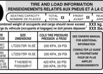
Payload – is the combined weight of cargo and passengers that the vehicle is carrying. The maximum payload for your vehicle can be found on the Tire Label on the B-Pillar or the edge of the driver’s door (vehicles exported outside the US and Canada may not have a Tire Label). Look for “THE COMBINED WEIGHT OF OCCUPANTS AND CARGO SHOULD NEVER EXCEED XXX kg OR XXX lb.” for maximum payload. The payload listed on the Tire Label is the maximum payload for the vehicle as built by the assembly plant. If any aftermarket or authorized-dealer installed equipment has been installed on the vehicle, the weight of the equipment must be subtracted from the payload listed on the Tire Label in order to determine the new payload.
WARNING: The appropriate loading capacity of your vehicle can be limited either by volume capacity (how much space is
available) or by payload capacity (how much weight the vehicle should carry). Once you have reached the maximum payload of your vehicle, do not add more cargo, even if there is space available. Overloading or improperly loading your vehicle can contribute to loss of vehicle control and vehicle rollover.
250
2010 F-150 (f12) Owners Guide, 3rd Printing USA (fus)
Example only:
Tires, Wheels and Loading
Cargo Weight – includes all weight added to the Base Curb Weight, including cargo and optional equipment. When towing, trailer tongue load or king pin weight is also part of cargo weight. GAW (Gross Axle Weight) – is the total weight placed on each axle (front and rear) – including vehicle curb weight and all payload.
251
2010 F-150 (f12) Owners Guide, 3rd Printing USA (fus)
Tires, Wheels and Loading
GAWR (Gross Axle Weight Rating) – is the maximum allowable weight that can be carried by a single axle (front or rear). These numbers are shown on the Safety Compliance Certification Label located on the B-Pillar or the edge of the driver’s door. The total load on each axle must never exceed its GAWR. Note: For trailer towing information refer to Trailer towing found in this chapter or the RV and Trailer Towing Guide provided by your authorized dealer.
GVW (Gross Vehicle Weight) – is the Vehicle Curb Weight + cargo + passengers. GVWR (Gross Vehicle Weight Rating) – is the maximum allowable weight of the fully loaded vehicle (including all options, equipment, passengers and cargo). The GVWR is shown on the Safety Compliance Certification Label located on the B-Pillar or the edge of the driver’s door. The GVW must never exceed the GVWR.
252
2010 F-150 (f12) Owners Guide, 3rd Printing USA (fus)
• Example only:
Tires, Wheels and Loading
WARNING: Exceeding the Safety Compliance Certification Label vehicle weight rating limits could result in substandard vehicle
handling or performance, engine, transmission and/or structural damage, serious damage to the vehicle, loss of control and personal injury.
253
2010 F-150 (f12) Owners Guide, 3rd Printing USA (fus)
Tires, Wheels and Loading
GCW (Gross Combined Weight) – is the weight of the loaded vehicle (GVW) plus the weight of the fully loaded trailer. GCWR (Gross Combined Weight Rating) – is the maximum allowable weight of the vehicle and the loaded trailer – including all cargo and passengers – that the vehicle can handle without risking damage. (Important: The towing vehicle’s braking system is rated for operation at GVWR, not at GCWR.) Separate functional brakes should be used for safe control of towed vehicles and for trailers where the GCW of the towing vehicle plus the trailer exceed the GVWR of the towing vehicle. The GCW must never exceed the GCWR. Maximum Loaded Trailer Weight – is the highest possible weight of a fully loaded trailer the vehicle can tow. It assumes a vehicle with only mandatory options, no cargo (internal or external), a tongue load of 10–15% (conventional trailer) or king pin weight of 15–25% (fifth wheel trailer), and driver only (150 lb. [68 kg]). Consult your authorized dealer (or the RV and Trailer Towing Guide provided by your authorized dealer) for more detailed information. Tongue Load or Fifth Wheel King Pin Weight – refers to the amount of the weight that a trailer pushes down on a trailer hitch. Examples: For a 5,000 lb. (2,268 kg) conventional trailer, multiply 5,000
by 0.10 and 0.15 to obtain a proper tongue load range of 500 to 750 lb. (227 to 340 kg). For an 11,500 lb. (5,216 kg) fifth wheel trailer, multiply by 0.15 and 0.25 to obtain a proper king pin load range of 1,725 to 2,875 lb. (782 to 1,304 kg)WARNING: Do not exceed the GVWR or the GAWR specified on the Safety Compliance Certification Label.
WARNING: Do not use replacement tires with lower load carrying capacities than the original tires because they may
lower the vehicle’s GVWR and GAWR limitations. Replacement tires with a higher limit than the original tires do not increase the GVWR and GAWR limitations.
254
2010 F-150 (f12) Owners Guide, 3rd Printing USA (fus)
Tires, Wheels and Loading
WARNING: Exceeding any vehicle weight rating limitation could result in serious damage to the vehicle and/or personal injury.
Steps for determining the correct load limit: 1. Locate the statement “The combined weight of occupants and cargo should never exceed XXX kg or XXX lb.” on your vehicle’s placard. 2. Determine the combined weight of the driver and passengers that will be riding in your vehicle. 3. Subtract the combined weight of the driver and passengers from XXX kg or XXX lb. 4. The resulting figure equals the available amount of cargo and luggage load capacity. For example, if the “XXX” amount equals 1,400 lb. and there will be five 150 lb. passengers in your vehicle, the amount of available cargo and luggage load capacity is 650 lb. (1400-750 (5 x 150) = 650 lb.). In metric units (635-340 (5 x 68) = 295 kg.) 5. Determine the combined weight of luggage and cargo being loaded on the vehicle. That weight may not safely exceed the available cargo and luggage load capacity calculated in Step 4. 6. If your vehicle will be towing a trailer, load from your trailer will be transferred to your vehicle. Consult this manual to determine how this reduces the available cargo and luggage load capacity of your vehicle. The following gives you a few examples on how to calculate the available amount of cargo and luggage load capacity: • Another example for your vehicle with 1,400 lb. (635 kg) of cargo and luggage capacity. You decide to go golfing. Is there enough load capacity to carry you, 4 of your friends and all the golf bags? You and four friends average 220 lb. (99 kg) each and the golf bags weigh approximately 30 lb. (13.5 kg) each. The calculation would be: 1400 - (5 x 220) - (5 x 30) = 1400 - 1100 - 150 = 150 lb. Yes, you have enough load capacity in your vehicle to transport four friends and your golf bags. In metric units, the calculation would be: 635 kg - (5 x 99 kg) - (5 x 13.5 kg) = 635 - 495 - 67.5 = 72.5 kg. • A final example for your vehicle with 1,400 lb. (635 kg) of cargo and luggage capacity. You and one of your friends decide to pick up cement from the local home improvement store to finish that patio you have been planning for the past 2 years. Measuring the inside of the vehicle with the rear seat folded down, you have room for 12-100 lb. (45 kg) bags of cement. Do you have enough load capacity
255
2010 F-150 (f12) Owners Guide, 3rd Printing USA (fus)
Tires, Wheels and Loading
to transport the cement to your home? If you and your friend each weigh 220 lb. (99 kg), the calculation would be: 1400 - (2 x 220) - (12
x 100) = 1400 - 440 - 1200 = - 240 lb. No, you do not have enough cargo capacity to carry that much weight. In metric units, the calculation would be: 635 kg - (2 x 99 kg) - (12 x 45 kg) = 635 - 198 - 540 = -103 kg. You will need to reduce the load weight by at least 240 lb. (104 kg). If you remove 3-100 lb. (45 kg) cement bags, then the load calculation would be: 1400 - (2 x 220) - (9 x 100) = 1400 - 440 - 900 = 60 lb. Now you have the load capacity to transport the cement and your friend home. In metric units, the calculation would be: 635 kg - (2 x 99 kg) - (9 x 45 kg) = 635 - 198 - 405 = 32 kg.The above calculations also assume that the loads are positioned in your vehicle in a manner that does not overload the Front or the Rear Gross Axle Weight Rating specified for your vehicle on the Safety Compliance Certification Label found on the edge of the driver’s door.
Special loading instructions for owners of pick-up trucks and utility-type vehicles
WARNING: For important information regarding safe operation of this type of vehicle, see the Preparing to drive your vehicle
section in the Driving chapter of this owner’s guide.
WARNING: Loaded vehicles may handle differently than unloaded vehicles. Extra precautions, such as slower speeds and
increased stopping distance, should be taken when driving a heavily loaded vehicle.
Your vehicle can haul more cargo and people than most passenger cars. Depending upon the type and placement of the load, hauling cargo and people may raise the center of gravity of the vehicle.
TRAILER TOWING Your vehicle may tow a class I, II, III or IV trailer provided the maximum trailer weight is less than or equal to the maximum trailer weight listed for your engine and rear axle ratio on the following charts. If your vehicle is not equipped with a heavy-duty trailer towing package, the maximum weight your vehicle can tow is limited to 5,000 lb (2,268 kg). 256
2010 F-150 (f12) Owners Guide, 3rd Printing USA (fus)
Tires, Wheels and Loading
Note: Do not exceed trailer weight of 5,000 lb (2,268 kg) when towing with bumper only. Exceeding the maximum GCWR could result in extensive damage to your vehicle and personal injury. Your vehicle’s load capacity is designated by weight, not by volume, so you cannot necessarily use all available space when loading a vehicle. Towing a trailer places an additional load on your vehicle’s engine, transmission, axle, brakes, tires and suspension. Inspect these components carefully periodically during, and after any towing operation. Follow these guidelines to ensure safe towing: • 45 ft2 (4.18 m2) without the Trailer Tow Package or the Heavy • 60 ft2 (5.52 m2) with the Trailer Tow Package or the Heavy Payload
Payload Package.
Package.
Regular Cab 4x2 (126” wheelbase)
Engine
Rear axle ratio
4.6L 2V
3.55
3.73Maximum GCWR - lb
(kg)
10400 (4717) 10900 (4944)
Maximum
Trailer Weight
- lb (kg)
5400 (2449) 5900 (2676)
Regular Cab 4x4 (126” wheelbase)
Engine
Rear axle ratio
4.6L 2V
4.6L 3V
5.4L
3.73
3.55
3.73
3.313.55/3.73
Maximum GCWR - lb
(kg)
10900 (4944) 12900 (5851) 13300 (6033) 13000 (5897) 13900 (6305)
Maximum
Trailer Weight
- lb (kg)
5700 (2585) 7700 (3493) 8000 (3629) 7700 (3493) 8600 (3901)
257
2010 F-150 (f12) Owners Guide, 3rd Printing USA (fus)
Tires, Wheels and Loading
Regular Cab 4x2 (145” wheelbase)
Engine
Rear axle ratio
4.6L 2V
4.6L 3V
5.4L
5.4L (Heavy
Duty)
3.55
3.73
3.31
3.55
3.15
3.55
3.73Maximum GCWR - lb
(kg)
10600 (4808) 11100 (5035) 13100 (5942) 13600 (6169) 13200 (5987) 15000 (6804) 16700 (7575)
Maximum
Trailer Weight
- lb (kg)
5500 (2495) 6000 (2722) 8000 (3629) 8400 (3810) 8000 (3629) 9800 (4445) 11300 (5126)
Regular Cab 4x4 (145” wheelbase)
Engine
Rear axle ratio
Maximum GCWR - lb
(kg)
11100 (5035) 13100 (5942) 13600 (6169) 13200 (5987) 15000 (6804) 17000 (7711)
Maximum
Trailer Weight
- lb (kg)
5800 (2631) 7700 (3493) 8200 (3719) 7700 (3493) 9500 (4309) 11300 (5126)
3.73
3.55
3.73
3.313.55/3.73
3.73
SuperCab 4x2 (145” wheelbase) Rear axle ratio
Maximum GCWR - lb
3.55
3.73
3.31
3.55(kg)
10600 (4808) 11100 (5035) 13500 (6123) 14900 (6759)
Maximum
Trailer Weight
- lb (kg)
5300 (2404) 5800 (2631) 8100 (3674) 9500 (4309)
4.6L 2V
4.6L 3V
5.4L
5.4L (Heavy
Duty)
Engine
4.6L 2V
4.6L 3V
258
2010 F-150 (f12) Owners Guide, 3rd Printing USA (fus)
Tires, Wheels and Loading
SuperCab 4x2 (145” wheelbase) Rear axle ratio
Maximum GCWR - lb
3.15
3.55
3.73(kg)
14000 (6350) 15200 (6895) 16900 (7666)
SuperCab 4x4 (145” wheelbase) Rear axle ratio
Maximum GCWR - lb
3.73
3.55
3.73
3.313.55/3.73
3.73
(kg)
11100 (5035) 13500 (6123) 15100 (6849) 14000 (6350) 15400 (6985) 17100 (7756)*
Maximum
Trailer Weight
- lb (kg)
8600 (3900) 9800 (4445) 11300 (5126)
Maximum
Trailer Weight
- lb (kg)
5500 (2495) 7900 (3583) 9400 (4264) 8300 (3765) 9700 (4400) 11200 (5080)*
Engine
5.4L
Engine
4.6L 2V
4.6L 3V
5.4L
5.4L (Heavy
Duty)
*Maximum GCWR and trailer weight when equipped with Max Trailer Tow package.
SuperCab 4x2 (163” wheelbase) Rear axle ratio
Maximum GCWR - lb
(kg)
Maximum
Trailer Weight
- lb (kg)
3.73
17100 (7756)
11300 (5126)
SuperCab 4x4 (163” wheelbase) Rear axle ratio
Maximum GCWR - lb
(kg)
Maximum
Trailer Weight
- lb (kg)
3.73
17100 (7756)
11100 (5035)
Engine
5.4L (Heavy
Duty)
Engine
5.4L (Heavy
Duty)
259
2010 F-150 (f12) Owners Guide, 3rd Printing USA (fus)
Tires, Wheels and Loading
Engine
4.6L 2V
4.6L 3V
5.4L
SuperCrew 4x2 (145” wheelbase) Rear axle ratio
Maximum GCWR - lb
Maximum
Trailer Weight
3.55
3.73
3.15
3.31
3.55
3.15
3.55
3.73(kg)
10600 (4808) 11100 (5035) 13000 (5897) 13500 (6123) 14900 (6759) 14000 (6350) 15300 (6940) 16900 (7666)
- lb (kg)
5200 (2359) 5700 (2585) 7500 (3402) 8100 (3674) 9400 (4264) 8500 (3856) 9800 (4445) 11300 (5126)
SuperCrew 4x2 (145” wheelbase) Harley-Davidson
Engine
Rear axle ratio
5.4L
3.73
Maximum GCWR - lb
(kg)
11200 (5080)
Maximum
Trailer Weight
- lb (kg)
5300 (2404)
SuperCrew 4x4 (145” wheelbase) Rear axle ratio
Maximum GCWR - lb
3.55
3.73
3.313.55/3.73
3.73
(kg)
13500 (6123) 15100 (6849) 14000 (6350) 15500 (7031) 17100 (7756)*
Maximum
Trailer Weight
- lb (kg)
7700 (3493) 9300 (4218) 8100 (3674) 9600 (4355) 11200 (5080)*
Engine
4.6L 3V
5.4L
5.4L (Heavy
Duty)
*Maximum GCWR and trailer weight when equipped with Max Trailer Tow package.
260
2010 F-150 (f12) Owners Guide, 3rd Printing USA (fus)
Tires, Wheels and Loading
SuperCrew 4x4 (145” wheelbase) Harley-Davidson
Engine
Rear axle ratio
5.4L
3.73
Maximum GCWR - lb
(kg)
11200 (5080)
Maximum
Trailer Weight
- lb (kg)
5100 (2313)
SuperCrew 4x2 (157” wheelbase) Rear axle ratio
Maximum GCWR - lb
Maximum
Trailer Weight
3.55
3.73
3.31
3.55
3.15
3.55
3.73(kg)
10600 (4808) 11100 (5035) 13500 (6123) 14900 (6759) 14000 (6350) 15300 (6940) 17000 (7711)
- lb (kg)
5100 (2313) 5600 (2540) 8000 (3629) 9300 (4218) 8400 (3810) 9700 (4400) 11300 (5126)
SuperCrew 4x4 (157” wheelbase) Rear axle ratio
Maximum GCWR - lb
3.55
3.73
3.313.55/3.73
3.73
(kg)
13500 (6123) 15100 (6849) 14000 (6350) 15500 (7031) 17100 (7756)*
Maximum
Trailer Weight
- lb (kg)
7600 (3448) 9200 (4173) 8000 (3629) 9500 (4309) 11100 (5035)*
Engine
4.6L 2V
4.6L 3V
5.4L
Engine
4.6L 3V
5.4L
5.4L (Heavy
Duty)
*Maximum GCWR and trailer weight when equipped with Max Trailer Tow package.
WARNING: Do not exceed the GVWR or the GAWR specified on the certification label.
261
2010 F-150 (f12) Owners Guide, 3rd Printing USA (fus)
Tires, Wheels and Loading
WARNING: Towing trailers beyond the maximum recommended gross trailer weight exceeds the limit of the vehicle and could
result in engine damage, transmission damage, structural damage, loss of vehicle control, vehicle rollover and personal injury.
Class IV trailer towing package.
Trailer frontal area considerations: • Not to exceed towing vehicle frontal area 36 ft2 (3.4 m2) without the • Not to exceed 45 ft2 (4.18 m2) with the Class IV trailer towing • Not to exceed 60 ft2 (5.52 m2) with the Class IV trailer towing
package for vehicles with 3.15 rear axle ratio only.
package - excluding vehicles with 3.15 rear axle ratio.
Preparing to tow Use the proper equipment for towing a trailer and make sure it is properly attached to your vehicle. Contact your authorized dealer or a reliable trailer dealer as soon as possible if you require assistance. Hitches Do not use hitches that clamp onto the vehicle’s bumper or attach to the axle. You must distribute the load in your trailer so that 10–15% of the total weight of the trailer is on the tongue. Weight-distributing hitch When hooking-up a trailer using a load-equalizing hitch, always use the following procedure: 1. Park the unloaded vehicle on a level surface. With the ignition on and all doors closed, allow the vehicle to stand for several minutes so that it can level. 2. Measure the height of a reference point on the front and rear bumpers at the center of the vehicle. 3. Attach the trailer to the vehicle and adjust the hitch equalizers so that the front bumper height is within 1⁄2 in. (13 mm) of the reference point. After proper adjustment, the rear bumper should be no higher than in Step 2.
WARNING: Do not adjust a weight-distributing hitch to any position where the rear bumper of the vehicle is higher than it was before attaching the trailer. Doing so will defeat the function of the weight-distributing hitch, which may cause unpredictable handling, and could result in serious personal injury.
262
2010 F-150 (f12) Owners Guide, 3rd Printing USA (fus)
Tires, Wheels and Loading
Safety chains Always connect the trailer’s safety chains to the frame or hook retainers of the vehicle hitch. To connect the trailer’s safety chains, cross the chains under the trailer tongue and allow slack for turning corners. If you use a rental trailer, follow the instructions that the rental agency gives to you. Do not attach safety chains to the bumper.
Trailer brakes Electric brakes and manual, automatic or surge-type trailer brakes are safe if installed properly and adjusted to the manufacturer’s specifications. The trailer brakes must meet local and Federal regulations.
WARNING: Do not connect a trailer’s hydraulic brake system directly to your vehicle’s brake system. Your vehicle may not have enough braking power and your chances of having a collision greatly increase.
The braking system of the tow vehicle is rated for operation at the GVWR not GCWR. Integrated trailer brake controller (if equipped) Your vehicle may be equipped with a fully integrated electronic trailer brake controller (TBC). When used properly, the TBC helps ensure smooth and effective trailer braking by powering the trailer’s electric brakes with a proportional output based on the towing vehicle’s brake pressure.
WARNING: The Ford TBC has only been verified to be compatible with trailers having electric-actuated drum brakes
(one to four axles) and not hydraulic surge or electric-over-hydraulic types. It is the responsibility of the customer to ensure that the trailer brakes are adjusted appropriately, functioning normally and all electric connections are properly made. Failure to do so may result in loss of vehicle control, crash or serious injury.
263
2010 F-150 (f12) Owners Guide, 3rd Printing USA (fus)
Tires, Wheels and Loading
TRAILER BRAKE
The TBC user interface consists of the following: 1. +/- (GAIN adjustment buttons): Pressing these buttons will adjust the TBC’s power output to the trailer brakes (in 0.5 increments). The GAIN setting can be increased to a maximum of 10.0 or decreased to a minimum of 0 (no trailer braking). Pressing and holding a button will raise or lower the setting continuously. The gain setting will display in the message center as follows: TBC GAIN = XX.X. The trailer brake controller (TBC) is designed to display three items of information in the instrument cluster message center. These are: gain setting, output bar graph, and trailer connectivity status. They will appear as follows in the message center. • TBC GAIN = XX.X NO TRAILER: The instrument cluster message
center will display the current gain setting during a given ignition cycle and when adjusting the gain. This message is also displayed during manual activation without a trailer connected or when gain adjustments are made with no trailer connected.
• TBC GAIN = XX.X OUTPUT = //////: When the vehicle’s brake pedal is pushed, or when the manual control is activated, bar indicators will illuminate in the instrument cluster message center to indicate the amount of power going to the trailer brakes relative to the brake pedal or manual control input. One bar indicates the least amount of output with six bars indicating maximum output. • TRAILER CONNECTED: This message is displayed when a correct
trailer wiring connection (a trailer with electric trailer brakes) has been sensed during a given ignition cycle.
• TRAILER DISCONNECTED: This message is displayed and accompanied by a single chime, when a trailer connection was determined and then a disconnection, either intentionally or unintentionally, has been sensed during a given ignition cycle. It is also displayed if a truck or trailer wiring fault occurs causing the trailer to appear disconnected. This message is also displayed during manual activation without a trailer connected.
2. Manual control lever: Slide the control lever to the left to activate power to the trailer’s electric brakes independent of the tow vehicle’s brakes (see the following Procedure for adjusting GAIN section for instructions on proper use of this feature). If the manual control is 264
2010 F-150 (f12) Owners Guide, 3rd Printing USA (fus)
Tires, Wheels and Loading
activated while the brake is also applied, the greater of the two inputs determines the power sent to the trailer brakes. • Stop Lamps: Activating the TBC manual control lever will illuminate both the trailer brake lamps and the tow vehicle brake lamps except the center high-mount stop lamp (presuming proper trailer electrical connection). Pressing the vehicle brake pedal will also illuminate both trailer and vehicle brake lamps. Procedure for adjusting GAIN: The GAIN setting is used to set the TBC for the specific towing condition and should be changed as towing conditions change. Changes to towing conditions include trailer load, vehicle load, road conditions and weather. The GAIN should be set to provide the maximum trailer braking assistance while ensuring the trailer wheels do not lock when braking. Locked trailer wheels may lead to trailer instability. Note: This should only be performed in a traffic free environment at speeds of approximately 20–25 mph (30–40 km/h). 1. Make sure the trailer brakes are in good working condition, functioning normally, and properly adjusted. See your trailer dealer if necessary. 2. Hook up the trailer and make the electrical connections according to the trailer manufacturer’s instructions. 3. When a trailer with electric brakes is plugged in, the TRAILER