- 2007 Ford F 350 Owners Manuals
- Ford F 350 Owners Manuals
- 2012 Ford F 350 Owners Manuals
- Ford F 350 Owners Manuals
- 2008 Ford F 350 Owners Manuals
- Ford F 350 Owners Manuals
- 2002 Ford F 350 Owners Manuals
- Ford F 350 Owners Manuals
- 2003 Ford F 350 Owners Manuals
- Ford F 350 Owners Manuals
- 2004 Ford F 350 Owners Manuals
- Ford F 350 Owners Manuals
- 2011 Ford F 350 Owners Manuals
- Ford F 350 Owners Manuals
- 2010 Ford F 350 Owners Manuals
- Ford F 350 Owners Manuals
- 2006 Ford F 350 Owners Manuals
- Ford F 350 Owners Manuals
- 2001 Ford F 350 Owners Manuals
- Ford F 350 Owners Manuals
- 2009 Ford F 350 Owners Manuals
- Ford F 350 Owners Manuals
- 2005 Ford F 350 Owners Manuals
- Ford F 350 Owners Manuals
- Download PDF Manual
-
5.4L 6.8L
4x4 with automatic transmission
3.73
4.10
3.736123 (13500) 6804 (15000) 7711 (17000)
3084 (6800) 3765 (8300) 4627 (10200)
F-350 Regular Chassis Cab Dual Rear Wheel (Fifth Wheel
Engine
Rear axle
ratio
Towing) Maximum GCWR -
kg (lbs.)
5.4L 5.4L 6.8L 6.8L
5.4L 5.4L 6.8L 6.8L
5.4L 5.4L 6.8L 6.8L
4x2 with manual transmission 3.73
4.10
3.73
4.306123 (13500) 6804 (15000) 7484 (16500) 9072 (20000)
4x2 with automatic transmission
6123 (13500) 6804 (15000) 7711 (17000) 9072 (20000)
3.73
4.10
3.73
4.30
4x4 with manual transmission 3.73
4.10
3.73
4.306123 (13500) 6804 (15000) 7484 (16500) 9072 (20000)
Maximum
trailer weight -
kg (lbs.)
3130 (6900) 3810 (8400) 4400 (9700) 5987 (13200)
3175 (7000) 3856 (8500) 4672 (10300) 6033 (13300)
2903 (6400) 3583 (7900) 4172 (9200) 5759 (12700)
161
Driving
F-350 Regular Chassis Cab Dual Rear Wheel (Fifth Wheel
Engine
Rear axle
ratio
Towing) Maximum GCWR -
kg (lbs.)
Maximum
trailer weight -
kg (lbs.)
5.4L 5.4L 6.8L 6.8L
4x4 with automatic transmission
3.73
4.10
3.73
4.306123 (13500) 6804 (15000) 7711 (17000) 9072 (20000)
2948 (6500) 3629 (8000) 4445 (9800) 5806 (12800)
F-350 SuperCab Chassis Cab Single Rear Wheel (Fifth Wheel
Engine
Rear axle
ratio
Towing) Maximum GCWR -
kg (lbs.)
4x2 with manual transmission 3.73
4.10
3.736123 (13500) 6804 (15000) 7484 (16500)
4x2 with automatic transmission
6123 (13500) 6804 (15000) 7711 (17000)
3.73
4.10
3.73
4x4 with manual transmission 3.73
4.10
3.736123 (13500) 6804 (15000) 7484 (16500)
4x4 with automatic transmission
3.73
4.10
3.736123 (13500) 6804 (15000) 7711 (17000)
5.4L 5.4L 6.8L
5.4L 5.4L 6.8L
5.4L 5.4L 6.8L
5.4L 5.4L 6.8L
162
Maximum
trailer weight -
kg (lbs.)
3130 (6900) 3810 (8400) 4400 (9700)
3130 (6900) 3810 (8400) 4671 (10300)
2903 (6400) 3583 (7900) 4218 (9300)
2948 (6500) 3629 (8000) 4445 (9800)
6.8L 6.8L
6.8L 6.8L
6.8L 6.8L
6.8L 6.8L
F-350 SuperCab Chassis Cab Dual Rear Wheel (Fifth Wheel
Driving
Engine
Rear axle
ratio
Towing) Maximum GCWR -
kg (lbs.)
4x2 with manual transmission 3.73
4.307484 (16500) 9072 (20000)
4x2 with automatic transmission
7711 (17000) 9072 (20000)
3.73
4.30
4x4 with manual transmission 3.73
4.307484 (16500) 9072 (20000)
Maximum
trailer weight -
kg (lbs.)
4264 (9400) 5851 (12900)
4491 (9900) 5851 (12900)
4082 (9000) 5670 (12500)
4x4 with automatic transmission
3.73
4.307711 (17000) 9072 (20000)
4309 (9500) 5670 (12500)
F-350 Crew Cab Chassis Cab Single Rear Wheel (Fifth Wheel
Engine
Rear axle
ratio
Towing) Maximum GCWR -
kg (lbs.)
Maximum
trailer weight -
kg (lbs.)
5.4L 5.4L 6.8L
5.4L 5.4L 6.8L
4x2 with manual transmission 3.73
4.10
3.736123 (13500) 6804 (15000) 7484 (16500)
4x2 with automatic transmission
3.73
4.10
3.736123 (13500) 6804 (15000) 7711 (17000)
3039 (6700) 3719 (8200) 4309 (9500)
3039 (6700) 3719 (8200) 4580 (10100)
163
Driving
F-350 Crew Cab Chassis Cab Single Rear Wheel (Fifth Wheel
Engine
Rear axle
ratio
Towing) Maximum GCWR -
kg (lbs.)
Maximum
trailer weight -
kg (lbs.)
5.4L 5.4L 6.8L
5.4L 5.4L 6.8L
4x4 with manual transmission 3.73
4.10
3.736123 (13500) 6804 (15000) 7484 (16500)
4x4 with automatic transmission
3.73
4.10
3.736123 (13500) 6804 (15000) 7711 (17000)
2812 (6200) 3493 (7700) 4128 (9100)
2858 (6300) 3538 (7800) 4354 (9600)
F-350 Crew Cab Chassis Cab Dual Rear Wheel (Fifth Wheel
Engine
Rear axle
ratio
Towing) Maximum GCWR -
kg (lbs.)
4x2 with manual transmission 3.73
4.307484 (16500) 9072 (20000)
4x2 with automatic transmission
7711 (17000) 9072 (20000)
3.73
4.30
4x4 with manual transmission 3.73
4.307484 (16500) 9072 (20000)
Maximum
trailer weight -
kg (lbs.)
9200 (4173) 5761 (12700)
4400 (9700) 5761 (12700)
3946 (8700) 5534 (12200)
4x4 with automatic transmission
3.73
4.307711 (17000) 9072 (20000)
4172 (9200) 5532 (12200)
6.8L 6.8L
6.8L 6.8L
6.8L 6.8L
6.8L 6.8L
164
F-450 Regular Chassis Cab Dual Rear Wheel (Fifth Wheel
Driving
Engine
Rear axle
ratio
Towing) Maximum GCWR -
kg (lbs.)
4x2 with manual transmission
4.88/5.38
4x2 with automatic transmission9979 (22000)
4.88
5.38
4x4 with manual transmission10886 (24000) 11793 (26000)
4.88/5.38
4x4 with automatic transmission9979 (22000)
4.88
5.3810886 (24000) 11793 (26000)
7394 (16300) 8301 (18300)
F-450 SuperCab Chassis Cab Dual Rear Wheel (Fifth Wheel
Engine
Rear axle
ratio
Towing) Maximum GCWR -
kg (lbs.)
Maximum
trailer weight -
kg (lbs.)
6577 (14500)
7530 (16600) 8437 (18600)
6441 (14200)
Maximum
trailer weight -
kg (lbs.)
6441 (14200)
7348 (16200) 8255 (18200)
6260 (13800)
4x2 with manual transmission
4.88/5.38
4x2 with automatic transmission9979 (22000)
4.88
5.38
4x4 with manual transmission10886 (24000) 11793 (26000)
4.88/5.38
4x4 with automatic transmission9979 (22000)
4.88
5.3810886 (24000) 11793 (26000)
7167 (15800) 8074 (17800)
165
6.8L
6.8L 6.8L
6.8L
6.8L 6.8L
6.8L
6.8L 6.8L
6.8L
6.8L 6.8L
6.8L
6.8L 6.8L
6.8L
6.8L 6.8L
Driving
F-450 Crew Cab Chassis Cab Dual Rear Wheel (Fifth Wheel
Engine
Rear axle
ratio
Towing) Maximum GCWR -
kg (lbs.)
4x2 with manual transmission
4.88/5.38
4x2 with automatic transmission9979 (22000)
4.88
5.38
4x4 with manual transmission10886 (24000) 11793 (26000)
4.88/5.38
4x4 with automatic transmission9979 (22000)
Maximum
trailer weight -
kg (lbs.)
6350 (14000)
7257 (16000) 8165 (18000)
6214 (13700)
4.88
5.3810886 (24000) 11793 (26000)
7121 (15700) 8029 (17700)
F-550 Regular Cab Chassis Cab Dual Rear Wheel (Fifth Wheel
Engine
Rear axle
ratio
Towing) Maximum GCWR -
kg (lbs.)
Maximum
trailer weight -
kg (lbs.)
6.8L 6.8L
6.8L 6.8L
4x2 with automatic transmission
4.88
5.3810886 (24000) 11793 (26000)
7484 (16500) 8391 (18500)
4x4 with automatic transmission
4.88
5.3810886 (24000) 11793 (26000)
7348 (16200) 8255 (18200)
166
Driving
F-550 SuperCab Chassis Cab Dual Rear Wheel (Fifth Wheel
Engine
Rear axle
ratio
Towing) Maximum GCWR -
kg (lbs.)
Maximum
trailer weight -
kg (lbs.)
6.8L 6.8L
6.8L 6.8L
4x2 with automatic transmission
4.88
5.3810886 (24000) 11793 (26000)
7348 (16200) 8255 (18200)
4x4 with automatic transmission
4.88
5.3810886 (24000) 11793 (26000)
7121 (15700) 8029 (17700)
F-550 Crew Cab Chassis Cab Dual Rear Wheel (Fifth Wheel
Engine
Rear axle
ratio
Towing) Maximum GCWR -
kg (lbs.)
Maximum
trailer weight -
kg (lbs.)
6.8L 6.8L
6.8L 6.8L
4x2 with automatic transmission
4.88
5.3810886 (24000) 11793 (26000)
7212 (15900) 8119 (17900)
4x4 with automatic transmission
4.88
5.3810886 (24000) 11793 (26000)
7076 (15600) 7983 (17600)
Preparing to tow Use the proper equipment for towing a trailer and make sure it is properly attached to your vehicle. See your dealer or a reliable trailer dealer if you require assistance.
Hitches Do not use hitches that clamp onto the vehicle’s bumper or attach to the axle. You must distribute the load in your trailer so that 10%–15% of the total weight of the trailer is on the tongue.
167
Driving
Load equalizing hitch When hooking up a trailer using a load equalizing hitch, always use the following procedure: 1. Park the unloaded vehicle on a level surface. With the ignition on and all doors closed, allow the vehicle to stand for several minutes so that it can level. 2. Measure the height of a reference point on the front and rear bumpers at the center of the vehicle. 3. Attach the trailer to the vehicle and adjust the hitch equalizers so that the front bumper height is within 0–13 mm (0.5 in) of the reference point. After proper adjustment, the rear bumper should be no higher than in Step 2. Note: Adjusting an equalizing hitch so the rear bumper of the vehicle is higher than it was unloaded will defeat the function of the load equalizing hitch and may cause unpredictable handling. Safety chains Always connect the trailer’s safety chains to the frame or hook retainers of the vehicle hitch. To connect the trailer’s safety chains, cross the chains under the trailer tongue and allow slack for turning corners. If you use a rental trailer, follow the instructions that the rental agency gives to you. Do not attach safety chains to the bumper. Trailer brakes Electric brakes and manual, automatic or surge-type trailer brakes are safe if installed properly and adjusted to the manufacturer’s specifications. The trailer brakes must meet local and Federal regulations.
Do not connect a trailer’s hydraulic brake system directly to your vehicle’s brake system. Your vehicle may not have enough
braking power and your chances of having a collision greatly increase.
The braking system of the tow vehicle is rated for operation at the GVWR not GCWR. Trailer lamps Trailer lamps are required on most towed vehicles. Make sure your trailer lamps conform to local and Federal regulations. See your dealer or trailer rental agency for proper instructions and equipment for hooking up trailer lamps.
168
Driving
Using a step bumper (if equipped) The rear bumper is equipped with an integral hitch and only requires a ball with a 25.4 mm (one inch) shank diameter. The bumper has a 2,270
kg (5,000 lb.) trailer weight and 227 kg (500 lb.) tongue weight capacity. If it is necessary to relocate the trailer hitch ball position, a frame-mounted trailer hitch must be installed.Driving while you tow When towing a trailer: • Turn off the speed control. The speed control may shut off automatically when you are towing on long, steep grades. • Consult your local motor vehicle speed regulations for towing a trailer. • If your vehicle is equipped with a 4–speed automatic
transmission: To eliminate excessive transmission shifting, use a lower gear. This will also assist in transmission cooling. (For additional information, refer to the Understanding the positions of the 4–speed automatic transmission section in this chapter.
• If your vehicle is equipped with a 5–speed automatic
transmission: To eliminate excessive transmission shifting, activate the Tow/Haul feature. This will also assist in transmission cooling. (For additional information, refer to the Understanding the positions of the 5–speed automatic transmission section in this chapter.
• Anticipate stops and brake gradually. • Do not exceed the GCWR rating or transmission damage may occur. Servicing after towing If you tow a trailer for long distances, your vehicle will require more frequent service intervals. Refer to your scheduled maintenance guide for more information.
Trailer towing tips • Practice turning, stopping and backing up before starting on a trip to get the feel of the vehicle trailer combination. When turning, make wider turns so the trailer wheels will clear curbs and other obstacles.
• Allow more distance for stopping with a trailer attached. • The trailer tongue weight should be 10–15% of the loaded trailer • After you have traveled 80 km (50 miles), thoroughly check your
weight.
hitch, electrical connections and trailer wheel lug nuts.
169
Driving • To aid in engine/transmission cooling and A/C efficiency during hot weather while stopped in traffic, place the gearshift lever in P (Park) (automatic transmission) or N (Neutral) (manual transmissions). • Vehicles with trailers should not be parked on a grade. If you must
park on a grade, place wheel chocks under the trailer’s wheels.
Launching or retrieving a boat When backing down a ramp during boat launching or retrieval, • Do not allow the static water level to rise above the bottom edge of • Do not allow waves to break higher than 15 cm (6 inches) above the • Disconnect the trailer tow electrical connector to prevent blown fuses
bottom edge of the rear bumper.
the rear bumper.
caused by water entering into your trailer’s electrical wiring. Exceeding these limits may allow water to enter critical vehicle components, adversely affecting driveability, emissions and reliability. Replace front and rear axle lubricants any time the axles have been submerged in water. Axle lubricant quantities are not to be checked unless a leak is suspected.
ALL REAR WHEEL DRIVE (RWD) VEHICLES This applies to all cars and 4x2 trucks/sport utilities with rear wheel drive capability. An example of recreational towing is towing your vehicle behind a motorhome. The following recreational towing guidelines are designed to ensure that your transmission is not damaged. • Place the transmission in N (Neutral). • Maximum speed is 56 km/h (35 mph). • Maximum distance is 80 km (50 miles). If a distance of 80 km (50 miles) or a speed of 56 km/h (35 mph) must be exceeded, you must disconnect the driveshaft. Ford recommends the driveshaft be removed/installed only by a qualified technician. See your local dealer for driveshaft removal/installation. Improper removal/installation of the driveshaft can cause transmission fluid loss, damage to the driveshaft and internal transmission components.
170
Driving
RWD vehicles with 4x4 electronic shift transfer case or All Wheel Drive (AWD) vehicles with automatic transmissions: Regarding recreational towing or having your vehicle towed, 4x4 vehicles with electronic shift on the fly and AWD vehicles cannot be towed with any wheels on the ground (with the exception of moving it as a disabled vehicle off the road out of traffic).
SNOWPLOWING Note: Do not use your vehicle to snowplow until it has been driven at least 800 km (500 miles). Follow the severe duty schedule in your scheduled maintenance guide for engine oil and transmission fluid change intervals. Note: Ford does not install snowplows. For low speed snow removal, Ford offers a Snowplow Package Option on select 4x4 vehicles. To assist Ford dealers and equipment installers further prepare the vehicle for snowplowing, Ford includes instructions in the Ford Truck Body Builders Layout Book and Ford Truck Source Book. These instructions are available through your Ford dealer; they include the list of vehicle models recommended for snowplowing and snowplow weight limits. Use of the Snowplow Package Option, or its equivalent, along with these instructions will help avoid possible powertrain and chassis damage from snowplowing. The front and rear GAWR, GVWR, Total Accessory Reserve Capacity (TARC) and tire inflation pressures are found on the Safety Compliance Certification Label located on one of the vehicle’s door jambs. This label is applied to all vehicles completed by Ford Motor Company. Incomplete vehicles built by Ford Motor Company will have an Incomplete Vehicle Label in place of the Safety Compliance Label. The TARC does not apply to Incomplete Vehicles and will not be shown on the Incomplete Vehicle Label. The weight of the vehicle with occupants must never exceed the front and rear GAWR or the GVWR. The TARC is the weight of the permanently attached equipment that can be added to the vehicle without violating the vehicle’s Safety Compliance Certification. This includes the snowplow mounting hardware but does not include the removable portion of the snowplow assembly.
Installing the snowplow Read the following instructions before installing a snowplow: • Front GAWR must not exceed 63% of the GVW. Add ballast weight to the back of the vehicle, if necessary. Refer to the Safety Compliance Certification Label to find your vehicle’s front GAWR.
171
Driving • The Front Axle Accessory Reserve Capacity and the TARC listed on
the bottom right of the Safety Compliance Certification Label will determine whether or not the addition of a snowplow will overload your vehicle.
• The weight of the snowplow and supporting components distributed to
the front axle must not exceed the Front Axle Accessory Reserve Capacity. • The total weight of the snowplow and aftermarket equipment must • The weight of the installed snowplow and aftermarket equipment must
not exceed the TARC.
not load the vehicle beyond the GAWR (front/rear) and GVWR listed on the Safety Compliance Certification Label. • The total weight of the snowplow and aftermarket equipment must be
considered part of the payload and must not exceed the GCWR for towing. • Federal and most local regulations require additional exterior lamps for snowplow-equipped vehicles. Consult your dealer for additional information.
• Tires have their maximum inflation pressure and associated load rating
imprinted on the tire sidewall. This pressure may or may not be the same as that shown as recommended on the vehicle. The vehicle operator may have to adjust the tire inflation pressure to accommodate the snowplow and payload. Consult your dealer or equipment installer for help with proper inflation pressures.
• Federal and some local regulations require additional exterior lamps for snowplow-equipped vehicles. Consult your dealer for additional information. • After installing a snowplow to the vehicle, ensure the vehicle’s front toe alignment and front ride height are within specification (reset if required). These specifications are located in the vehicle’s Workshop Manual.
Note: Do not exceed the GVWR or the GAWR specified on the certification label.
Removing snowplow After removing a snowplow from the vehicle, ensure the vehicle’s front toe alignment and front ride height are within specification (reset if required).
172
Driving
Snowplowing with your air bag-equipped vehicle Your vehicle is equipped with a driver and passenger air bag Supplemental Restraint System (SRS) The SRS is designed to activate in certain frontal and offset frontal collisions when the vehicle sustains sufficient longitudinal deceleration. Careless or high speed driving while plowing snow which results in sufficient vehicle decelerations can deploy the air bag. Such driving also increases the risk of accidents.
All occupants of the vehicle, including the driver, should always properly wear their safety belts, even when an air bag (SRS) is
provided.
Never remove or defeat the “tripping mechanisms” designed into the snow removal equipment by its manufacturer. Doing so may cause damage to the vehicle and the snow removal equipment as well as possible air bag deployment.
Do not attempt to service, repair, or modify the Air Bag Supplemental Restraint System or its fuses. See your Ford or
Lincoln Mercury dealer.
Additional equipment such as snowplow equipment may effect the performance of the air bag sensors increasing the risk of
injury. Please refer to the Body Builders Layout Book for instructions about the appropriate installation of additional equipment.
Engine temperature while plowing When driving with a snowplow, your engine may run at a higher temperature than normal because the attached snowplow blade will restrict airflow to the radiator. If you are driving more than 24 km (15 miles) at temperatures above freezing, angle the plow blade either full left or full right to provide maximum airflow to the radiator. If you are driving less than 24 km (15 miles) at speeds up to 64 km/h (40 mph) in cold weather, you will not need to worry about blade position to provide maximum airflow. Refer to Transmission temperature gauge in the Instrument cluster chapter for transmission fluid temperature information.
173
Driving
areas at speeds below 8 km/h (5 mph).
4WD operation while plowing • Shift transfer case to 4x4 LOW (4WD Low) when plowing in small • Shift transfer case to 4x4 HIGH (4WD High) when plowing larger areas or light snow at higher speeds. Do not exceed 24 km/h (15
mph).• Do not shift the transmission from a forward gear to R (Reverse) until • If the vehicle is stuck, shift the transmission in a steady motion
the engine is at idle and the wheels are stopped.
between forward and reverse gears. Do not rock the vehicle for more than a few minutes. The transmission and tires may be damaged or the engine can overheat.
It is the owner’s responsibility to avoid engine overheating which can cause damage. Refer to Transmission temperature gauge in the Instrument cluster chapter for transmission fluid temperature information.
Do not spin the wheels at over 35 mph (55 km/h). The tires may fail and injure a passenger or bystander.
174
Roadside Emergencies
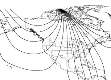
GETTING ROADSIDE ASSISTANCE To fully assist you should you have a vehicle concern, Ford Motor Company offers a complimentary roadside assistance program. This program is separate from the New Vehicle Limited Warranty. The service is available: • 24–hours, seven days a week • for the New Vehicle Limited Warranty period of three years or 60,000
km (36,000 miles), whichever occurs first on Ford and Mercury vehicles, and four years or 80,000 km (50,000 miles) on Lincoln vehicles.
Roadside assistance will cover: • changing a flat tire • jump-starts • lock-out assistance • limited fuel delivery • towing of your disabled vehicle to the nearest Ford Motor Company dealership, or your selling dealer if within 56.3 km (35 miles) of the nearest Ford Motor Company dealership (one tow per disablement). Even non-warranty related tows, like accidents or getting stuck in the mud or snow, are covered (some exclusions apply, such as impound towing or repossession).
Canadian customers refer to your Owner Information Guide for information on: • coverage period • exact fuel amounts • towing of your disabled vehicle • emergency travel expense reimbursement • travel planning benefits USING ROADSIDE ASSISTANCE Complete the roadside assistance identification card and place it in your wallet for quick reference. In the United States, this card is found in the Owner Guide portfolio in the glove compartment in Ford vehicles and is mailed to you if you own a Mercury or Lincoln. In Canada, the card is found in the Owner Information Guide in the glove compartment. U.S. Ford or Mercury vehicle customers who require roadside assistance, call 1–800–241–3673; Lincoln vehicle customers call 1–800–521–4140.
175
Roadside Emergencies
Canadian customers who require roadside assistance, call 1–800–665–2006. If you need to arrange roadside assistance for yourself, Ford Motor Company will reimburse a reasonable amount. To obtain reimbursement information, U.S. Ford or Mercury vehicles customers call 1-800-241-3673; Lincoln vehicle customers call 1–800–521–4140. Canadian customers who need to obtain reimbursement information, call 1–800–665–2006.
ROADSIDE COVERAGE BEYOND BASIC WARRANTY In the United States, you may purchase additional roadside assistance coverage beyond this period through the Ford Auto Club by contacting your Ford or Lincoln Mercury dealer. Similarly in Canada, for uninterrupted Roadside Assistance coverage, you may purchase extended coverage prior to your Basic Warranty’s Roadside Assistance expiring. For more information and enrollment, contact 1–877–294–2582 or visit our website at www.ford.ca.
HAZARD FLASHER The hazard flasher is located on the steering column, just behind the steering wheel. The hazard flashers will operate when the ignition is in any position. Push in the flasher control and all front and rear direction signals will flash. Press the flasher control again to turn them off. Use it when your vehicle is disabled and is creating a safety hazard for other motorists. Note: With extended use, the flasher may run down your battery.
FUEL PUMP SHUT-OFF SWITCH FUEL RESET This device stops the electric fuel pump from sending fuel to the engine when your vehicle has had a substantial jolt. After an accident, if the engine cranks but does not start, this switch may have been activated.
176
Roadside Emergencies
This switch is located in the front passenger’s footwell, by the kick panel access cover. To reset the switch: 1. Turn the ignition OFF. 2. Check the fuel system for leaks. 3. If no leaks are apparent, reset the switch by pushing in on the reset button. 4. Turn the ignition ON. 5. Wait a few seconds and return the key to OFF. 6. Make another check of leaks.
FUSES AND RELAYS
Fuses If electrical components in the vehicle are not working, a fuse may have blown. Blown fuses are identified by a broken wire within the fuse. Check the appropriate fuses before replacing any electrical components. Note: Always replace a fuse with one that has the specified amperage rating. Using a fuse with a higher amperage rating can cause severe wire damage and could start a fire.
15
177
Roadside Emergencies
Standard fuse amperage rating and color
COLOR
Fuse rating
2A 3A 4A 5A 7.5A 10A 15A 20A 25A 30A 40A 50A 60A 70A 80A
Mini fuses
Grey Violet Pink Tan
Brown
Red Blue Yellow Natural Green
— — — — —
Standard
fuses
Grey Violet Pink Tan
Brown
Red Blue Yellow Natural Green
— — — — —
Maxi fuses
— — — — — — —
Yellow
—
Green Orange
Red Blue Tan
Natural
Cartridge
maxi fuses
— — — — — — — Blue — Pink Green Red — — —
Fuse link cartridge
— — — — — — — Blue — Pink Green Red Yellow Brown Black
Passenger compartment fuse panel / power distribution box The fuse panel is located below and to the left of the steering wheel by the brake pedal. Remove the panel cover to access the fuses. To remove the fuse panel cover, turn the panel fasteners counterclockwise.
178
Roadside Emergencies
To remove a fuse use the fuse puller tool provided on the fuse panel cover.
The fuses are coded as follows.
Fuse/Relay Location
10
11Fuse Amp
Passenger Compartment Fuse Panel
Rating 15A*
— —
20A*
—
20A* 30A* 15A* 20A* 10A* 20A*
Description
Adjustable pedals Not used Not used Power point - instrument panel Not used Trailer tow turn/stop relay High beam headlamps/Flash to pass Backup lamps (Diesel engine only) Heated mirrors A/C clutch Radio (main)
179
Roadside Emergencies
Fuse Amp
Passenger Compartment Fuse Panel
Rating 20A* 5A* 15A*
— —
15A* 20A* 10A* 10A*
—
20A* 20A*
2A* 10A*
10A* 15A* 10A* 10A* 15A* 15A*
5A* 15A* 10A* 10A*
Description
Cigar lighter / OBD II Power mirrors/switches Daytime running lamps (DRL) Not used Not used Exterior lamps Turn lamps/Brake on-off switch (high) Body security module/4x4 module Fuel Injection Control Module (FICM) relay (Diesel engine only) Not used Engine control Engine control (gasoline engine only), Climate control (Diesel engine only) Brake pressure switch/Speed control 4-Wheel Anti-lock Brake System (4WABS) module, Variable Fan Control (VFC) (Diesel engine only) Air bags Ignition switch Run feed EATC module/Front blower relay coil Customer access Highbeam headlamps Clutch interlock switch (manual transmissions only), Transmission range sensor (automatic transmissions only) then to starter relay coil (all transmissions), 4x4
Radio (start) Front wiper Brake on-off switch Instrument clusterFuse/Relay Location
12
13
14
15
16
17
18
19
2021
22
2324
2526
27
28
29
30
3132
33
34
35180
Fuse/Relay Location
36
37
38
39
40
41
42
43
44
45
46
47
48
101
102
103104
105
106
107
108
109
110
111
112
113
114
115
116
601Roadside Emergencies
Fuse Amp
Passenger Compartment Fuse Panel
Rating 10A* 15A* 20A* 15A* 20A* 10A* 15A* 10A*
—
10A* 10A* 10A*
—
30A** 30A** 50A**
40A** 30A** 30A** 40A**
—
30A** 50A** 30A** 30A** 30A** 30A** 20A** 30A**
Description
PCM Memory Horn Trailer tow park lamps Trailer tow back-up lamps Fuel pump Instrument cluster Delayed accessory Fog lamps Not used Ignition switch Run/Start feed Left-hand lowbeam Right-hand lowbeam Not used Trailer tow electric brake Door locks/Body security module Ignition switch (gasoline engine only), FICM power (Diesel engine only) Heated backlight Fuel heater (Diesel engine only) Front wiper main Front blower motor Not used Heated seats Ignition switch 4WD/Shift on the fly Left-hand power seats Starter motor Right-hand power seats Trailer tow battery charge Ignition switch
30A CB*** Window motors, Moonroof
181
Roadside Emergencies
Fuse/Relay Location
602
210
211
212
301
302
303
304
305
306
307Fuse Amp
Passenger Compartment Fuse Panel
Rating 60A**
— — — — — — — — — —
Description
4WABS module Not used Backup lamps relay (Diesel engine only) Not used Front blower motor relay Powertrain Control Module (PCM) relay Fuel heater relay (Diesel engine only) Heated backlight relay Trailer tow battery charge relay Delayed accessory relay Starter relay
* Mini Fuses ** Maxi Fuses ***Circuit Breaker Note: (Diesel engine only) The Fuel Injection Control Module (FICM) logic 15A mini-fuse is located in the underhood relay block.
CHANGING A FLAT TIRE If you get a flat tire while driving: • do not brake heavily. • gradually decrease the vehicle’s speed. • hold the steering wheel firmly. • slowly move to a safe place on the side of the road.
The use of tire sealants is not recommended and may compromise the integrity of your tires. The use of tire sealants
may also affect your tire pressure monitoring system (if equipped).
Spare tire information Your vehicle may be equipped with a spare tire that can be used as either a spare or a regular tire. The spare tire is not equipped with wheel trim. The wheel trim from the original wheel/tire may be used on the spare.
182
Roadside Emergencies
If your vehicle is equipped with 4WD, a spare tire of a different size than the road tires should not be used. Use of such a tire
could result in damage to driveline components and an increased risk of loss of vehicle control, vehicle rollover, personal injury or death.
Location of the spare tire and tools The spare tire and tools for your vehicle are stowed in the following locations:
Tool
Location
Spare tire (pick-up trucks only) Under the vehicle, just forward of
Jack, jack handle and lug wrench Regular cab, crew cab and
the rear bumper
SuperCab without rear bench seat: Fastened to floor pan behind rearmost seat on passenger side SuperCab with rear bench seat: Under rear bench on passenger side In the glove box
Key, spare tire lock
Removing the spare tire (with spare tire carrier only) 1. The following tools are required to remove the spare tire: • one handle extension and one typical extension. To assemble, align button with hole and slide parts together. To disconnect, depress button and pull apart.
• one wheel nut wrench. Slide over
square end of jack handle.
183
Roadside Emergencies • Vehicles equipped with dual rear wheels, insert the lug wrench extension into the lug wrench to reach the lug nuts.
2. Attach the spare tire lock key (A) to the jack handle (B).
3. Fully insert the jack handle through the bumper hole and into the guide tube. The key and lock will engage with a slight push and counterclockwise turn. Some resistance will be felt when turning the jack handle assembly. 4. Turn the handle counterclockwise and lower the spare tire until you can slide the tire rearward and the cable is slack. 5. Remove the retainer through the center of the wheel.
184
Roadside Emergencies
Tire change procedure 1. Park on a level surface, activate hazard flashers and set the parking brake. • Automatic transmission: Place gearshift lever in P (Park). • Manual transmission: Place • Electronic Shift On the Fly 4WD:
gearshift lever in R (Reverse).
Place transfer case in any position.
• Manual shift transfer case 4WD: Place transfer case in 2H, 4H or 4L.
To prevent the vehicle from moving when you change a tire, be sure the parking brake is set, then block (in both directions) the wheel that is diagonally opposite (other side and end of the vehicle) to the tire being changed.
2. Turn engine off and block the diagonally opposite wheel (block not provided). 3. Remove the jack, jack handle, lug wrench and spare tire from the stowage locations. 4. Use the tip of the lug wrench to remove any wheel trim.
185
Roadside Emergencies
5. Loosen each wheel lug nut one-half turn counterclockwise but do not remove them until the wheel is raised off the ground.
When one of the rear wheels is off the ground, the transmission alone will not prevent the vehicle from moving or slipping off the
jack, even if the transmission is in P (Park) (automatic transmission) or R (Reverse) (manual transmission). To prevent the vehicle from moving when you change the tire, be sure that the parking brake is set and the diagonally opposite wheel is blocked.
If the vehicle slips off the jack, you or someone else could be seriously injured.
The following steps apply to F250/F350 only: 6. Insert the hooked end of the jack handle into the jack and use the handle to slide the jack under the vehicle. 7. Position the jack according to the following guides: • Front (4x2)
186
• Front passenger side (4x4)
Roadside Emergencies
• Front driver side (4x4) Make sure the jack fits into the notched area next to the differential housing.
• Rear
187
Roadside Emergencies
Never use the front or rear differential as a jacking point.
To lessen the risk of personal injury, do not put any part of your body under the vehicle while changing a tire. Do not start the engine when your vehicle is on the jack. The jack is only meant for changing the tire.
8. Turn the jack handle clockwise until the wheel is completely off the ground and high enough to install the spare tire. 9. Remove the lug nuts with the lug wrench. 10. Replace the flat tire with the spare tire, making sure the valve stem is facing outward for all front wheels and single rear wheel vehicles. If replacing an inboard rear tire on dual rear wheel vehicles, the valve stem must be facing outward. If replacing the outboard wheel, the valve stem must be facing inward. Reinstall the lug nuts until the wheel is snug against the hub. Do not fully tighten the lug nuts until the wheel has been lowered. 11. Lower the wheel by turning the jack handle counterclockwise. Go to step 19. The following steps apply to F350 Chassis Cab F450/F550 only: 12. Slide the notched end of the jack handle over the release valve and use the handle to slide the jack under the vehicle. Make sure the valve is closed by turning it clockwise.
188
Roadside Emergencies
13. Position the jack according to the following guides: • Front (4x2) F350
• Front (4x2) F450/550
• Front driver side (4x4)
189
Roadside Emergencies • Front passenger side (4x4)
• Rear
14. Insert the jack handle into the pump linkage. 15. Use an up-and-down motion with the jack handle to raise the wheel completely off the ground. Hydraulic jacks are equipped with a pressure release valve that prevents lifting loads which exceed the jack’s rated capacity. 16. Remove the lug nuts with the lug wrench. 17. Replace the flat tire with the spare tire, making sure the valve stem is facing outward on all front an inboard rear wheels. If replacing the outboard wheel, the valve stem must be facing inward. Reinstall the lug nuts until the wheel is snug against the hub. Do not fully tighten the lug nuts until the wheel has been lowered. 18. Lower the wheel by slowly turning the release valve counterclockwise. Opening the release valve slowly will provide a more controlled rate of descent.
190
Roadside Emergencies
The following steps apply to all vehicles: 19. Remove the jack and fully tighten the lug nuts in the order shown. 20. Stow the flat tire. Refer to Stowing the spare tire if the vehicle is equipped with a spare tire carrier. 21. Stow the jack, jack handle and lug wrench. Make sure the jack is securely fastened so it does not rattle when driving. 22. Unblock the wheels. On vehicles equipped with single rear wheels, retighten the lug nuts to the specified torque at 800 km (500 miles) after any wheel disturbance (tire rotation, changing a flat tire, wheel removal, etc.). On vehicles equipped with dual rear wheels, retighten the wheel lug nuts to the specified torque at 160 km (100 miles), and again at 800 km (500
miles) of new vehicle operation and after any wheel disturbance (tire rotation, changing a flat tire, wheel removal, etc.).Bolt size
Wheel lug nut torque*
Nm 200-225
Lb-ft 150-165
M14 x 1.5
* Torque specifications are for nut and bolt threads free of dirt and rust. Use only Ford recommended replacement fasteners.On all two-piece flat wheel nuts, apply one drop of motor oil between the flat washer and the nut. Do not apply motor oil to the wheel nut threads or the wheel stud threads.
191
Roadside Emergencies
When a wheel is installed, always remove any corrosion, dirt or foreign materials present on the mounting surfaces of the wheel or the surface of the front disc brake hub and rotor that contacts the wheel. Installing wheels without correct metal-to-metal contact at the wheel mounting surfaces can cause the wheel nuts to loosen and the wheel to come off while the vehicle is in motion, resulting in loss of control.
Stowing the flat/spare tire 1. Lay the tire on the ground with the valve stem facing in the direction specified on the Tire Changing Instructions located with the jack hardware. 2. Slide the wheel partially under the vehicle and install the retainer through the wheel center. Pull on the cable to align the components at the end of the cable. 3. Turn the jack handle clockwise until the tire is raised to its stowed position underneath the vehicle. The effort to turn the jack handle increases significantly and the spare tire carrier ratchets or slips when the tire is raised to the maximum tightness. Tighten to the best of your ability, to the point where the ratchet/slip occurs, if possible. The spare tire carrier will not allow you to overtighten. If the spare tire carrier ratchets or slips with little effort, take the vehicle to your dealer for assistance at your earliest convenience. 4. Check that the tire lies flat against the frame and is properly tightened. Try to push or pull, then turn the tire to be sure it will not move. Loosen and retighten, if necessary. Failure to properly stow the spare tire may result in failure of the winch cable and loss of the tire. 5. Repeat this tightness check procedure when servicing the spare tire pressure (every six months, per scheduled maintenance guide), or at any time that the spare tire is disturbed through service of other components. 6. If removed, install the spare tire lock (if equipped) into the bumper drive tube with the spare tire lock key (if equipped) and jack handle.
192
Roadside Emergencies
JUMP STARTING YOUR VEHICLE
The gases around the battery can explode if exposed to flames, sparks, or lit cigarettes. An explosion could result in injury or
vehicle damage.
Batteries contain sulfuric acid which can burn skin, eyes and clothing, if contacted.
Do not attempt to push-start your vehicle. Automatic transmissions do not have push-start capability; also, the catalytic converter may become damaged.
Preparing your vehicle When the battery is disconnected or a new battery is installed, the transmission must relearn its shift strategy. As a result, the transmission may have firm and/or soft shifts. This operation is considered normal and will not affect function or durability of the transmission. Over time, the adaptive learning process will fully update transmission operation. 1. Use only a 12–volt supply to start your vehicle. 2. Do not disconnect the battery of the disabled vehicle as this could damage the vehicle’s electrical system. 3. Park the booster vehicle close to the hood of the disabled vehicle making sure the two vehicles do not touch. Set the parking brake on both vehicles and stay clear of the engine cooling fan and other moving parts. 4. Check all battery terminals and remove any excessive corrosion before you attach the battery cables. Ensure that vent caps are tight and level. 5. Turn the heater fan on in both vehicles to protect any electrical surges. Turn all other accessories off.
193
Roadside Emergencies
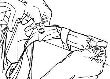
Connecting the jumper cables
+–
+–
1. Connect the positive (+) booster cable to the positive (+) terminal of the discharged battery. Note: In the illustrations, lightning bolts are used to designate the assisting (boosting) battery.
+–
+–
2. Connect the other end of the positive (+) cable to the positive (+) terminal of the assisting battery.
194
Roadside Emergencies
+–
+–
3. Connect the negative (-) cable to the negative (-) terminal of the assisting battery.
+–
+–
4. Make the final connection of the negative (-) cable to an exposed metal part of the stalled vehicle’s engine, away from the battery and the carburetor/fuel injection system. Do not use fuel lines, engine rocker covers or the intake manifold as grounding points.
Do not connect the end of the second cable to the negative (-) terminal of the battery to be jumped. A spark may cause an
explosion of the gases that surround the battery.
5. Ensure that the cables are clear of fan blades, belts, moving parts of both engines, or any fuel delivery system parts.
Jump starting 1. Start the engine of the booster vehicle and run the engine at moderately increased speed. 2. Start the engine of the disabled vehicle.
195
Roadside Emergencies
3. Once the disabled vehicle has been started, run both engines for an additional three minutes before disconnecting the jumper cables.
Removing the jumper cables
+–
+–
Remove the jumper cables in the reverse order that they were connected. 1. Remove the jumper cable from the ground metal surface. Note: In the illustrations, lightning bolts are used to designate the assisting (boosting) battery.
+–
+–
2. Remove the jumper cable on the negative (-) connection of the booster vehicle’s battery.
196
Roadside Emergencies
+–
+–
3. Remove the jumper cable from the positive (+) terminal of the booster vehicle’s battery.
+–
+–
4. Remove the jumper cable from the positive (+) terminal of the disabled vehicle’s battery. After the disabled vehicle has been started and the jumper cables removed, allow it to idle for several minutes so the engine computer can relearn its idle conditions.
197
Roadside Emergencies
WRECKER TOWING
If you need to have your vehicle towed, contact a professional towing service or, if you are a member of a roadside assistance program, your roadside assistance service provider. On 4x2 vehicles, it is acceptable to tow the vehicle with the front wheels on the ground and the rear wheels off the ground using a wheel lift or a slingbelt with T-hooks. On 4x4 vehicles, it is recommended that your vehicle be towed with a wheel lift or flatbed equipment with all the wheels off the ground. However, a slingbelt with T-hooks and a wheel dolly can also be used if all four wheels are off the ground. An alternative for towing a 4x4 vehicle with a manual 4WD system is to: • put the transfer case in neutral, then put the 4WD shift lever in N • unlock the front hub locks (refer to Four wheel drive [4WD]
(Neutral).
Operation [if equipped] in the Driving chapter).
198
Roadside Emergencies • lift the rear wheels of the vehicle using a wheel lift or a sling belt with
T-hooks.
If the vehicle is towed by other means or incorrectly, vehicle damage may occur. Ford Motor Company produces a towing manual for all authorized tow truck operators. Have your tow truck operator refer to this manual for proper hook-up and towing procedures for your vehicle.
199
Customer Assistance
GETTING THE SERVICES YOU NEED
At home Ford Motor Company and Ford of Canada have authorized dealerships to service your vehicle. It is preferred that you return to the authorized dealer where your vehicle was purchased when warranty repairs are needed. However, you may also take your vehicle to another Ford Motor Company or Ford of Canada dealership authorized for warranty repairs. Repairs can be made at Lincoln Mercury dealers, however Jaguar, Land Rover, Mazda, Volvo and Aston Martin dealers are not qualified to perform Superduty repairs. Certain warranty repairs require special training though, so not all dealers are authorized to perform all warranty repairs. That means that depending on the warranty repair needed, the vehicle may need to be taken to another dealer. If a particular dealership cannot assist you, then contact the Customer Relationship Center. If you have questions or concerns, or are unsatisfied with the service you are receiving, follow these steps: 1. Contact your Sales Representative or Service Advisor at your selling/servicing dealership. 2. If your inquiry or concern remains unresolved, contact the Sales Manager or Service Manager at the dealership. 3. If the inquiry or concern cannot be resolved at the dealership level, please contact the Ford Customer Relationship Center.
Away from home If you own a Ford or Mercury vehicle and are away from home when your vehicle needs service, or if you need more help than the dealership could provide, after following the steps described above, contact the Ford Customer Relationship Center to find an authorized dealership to help you. In the United States: Ford Motor Company Customer Relationship Center 16800 Executive Plaza Drive P.O. Box 6248
Dearborn, Michigan 48121
1-800-392-3673 (FORD) (TDD for the hearing impaired: 1-800-232-5952) www.ford.com200
Customer Assistance
In Canada: Customer Relationship Centre Ford Motor Company of Canada, Limited P.O. Box 2000
Oakville, Ontario L6J 5E4
1-800-565-3673 (FORD) www.ford.ca If you own a Lincoln vehicle and are away from home when your vehicle needs service, or if you need more help than the dealership could provide, after following the steps described above, contact the Ford Customer Relationship Center to find an authorized dealership to help you. In the United States: Ford Motor Company Customer Relationship Center 16800 Executive Plaza Drive P.O. Box 6248
Dearborn, Michigan 48121
1-800-521-4140
(TDD for the hearing impaired: 1-800-232-5952) www.ford.com In Canada: Customer Relationship Centre Ford Motor Company of Canada, Limited P.O. Box 2000
Oakville, Ontario L6J 5E4
1-800-565-3673 (FORD) www.ford.ca In order to help you service your Ford or Lincoln Mercury vehicle, please have the following information available when contacting a Customer Relationship Center: • Your telephone number (home and business) • The name of the dealer and the city where the dealership is located • The year and make of your vehicle • The date of vehicle purchase • The current odometer reading • The vehicle identification number (VIN) If you still have a complaint involving a warranty dispute, you may wish to contact the Dispute Settlement Board (U.S.).201
Customer Assistance
In some states (in the U.S.) you must directly notify Ford in writing before pursuing remedies under your state’s warranty laws. Ford is also allowed a final repair attempt in some states. In the United States, a warranty dispute must be submitted to the Dispute Settlement Board before taking action under the Magnuson-Moss Warranty Act, or to the extent allowed by state law, before pursuing replacement or repurchase remedies provided by certain state laws. This dispute handling procedure is not required prior to enforcing state created rights or other rights which are independent of the Magnuson-Moss Warranty Act or state replacement or repurchase laws.
FORD EXTENDED SERVICE PLAN You can get more protection for your new car or light truck by purchasing Ford Extended Service Plan (Ford ESP) coverage. Ford ESP is an optional service contract which is backed by Ford Motor Company or Ford Motor Service Company (in the U.S.) and Ford of Canada (in Canada). It provides the following: • Benefits during the warranty period depending on the plan you
purchase (such as: reimbursement for rentals; coverage for certain maintenance and wear items).
• Protection against covered repair costs after your Bumper-to-Bumper
Warranty expires.
You may purchase Ford ESP from any participating Ford and Lincoln Mercury and Ford of Canada dealer. There are several plans available in various time, distance and deductible combinations which can be tailored to fit your own driving needs. Ford ESP also offers reimbursement benefits for towing and rental coverage. When you buy Ford ESP, you receive Peace-of-Mind protection throughout the United States and Canada, provided by a network of more than 5,000 participating Ford or Lincoln Mercury and Ford of Canada dealers. If you did not take advantage of the Ford Extended Service Plan at the time of purchasing your vehicle, you may still be eligible. Since this information is subject to change, please ask your dealer for complete details about Ford Extended Service Plan coverage options, or visit the Ford ESP website at www.ford-esp.com.
THE DISPUTE SETTLEMENT BOARD (U.S. ONLY) The Dispute Settlement Board is: • an independent, third-party arbitration program for warranty disputes.
202
Customer Assistance • available free to owners and lessees of qualifying Ford Motor Company
vehicles.
The Dispute Settlement Board may not be available in all states. Ford Motor Company reserves the right to change eligibility limitations, modify procedures and/or to discontinue this service without notice and without incurring obligations per applicable state law.
What kinds of cases does the Board review? Unresolved warranty repair concerns or vehicle performance concerns as on Ford and Lincoln Mercury cars and Ford and Lincoln Mercury light trucks which are within the terms of any applicable written new vehicle warranty are eligible for review, except those involving: • a non-Ford product • a non-Ford dealership • sales disputes between customer and dealer except those associated with warranty repairs or concerns with the vehicle’s performance as designed
maintenance and wear items)
service or product concern is being reviewed
• a request for reimbursement of consequential expenses unless a • items not covered by the New Vehicle Limited Warranty (including • alleged personal injury/property damage claims • cases currently in litigation • vehicles not used primarily for family, personal or household purposes (except in states where the Dispute Settlement Board is required to review commercial vehicles)
• vehicles with non-U.S. warranties Concerns are ineligible for review if the New Vehicle Limited Warranty has expired at receipt of your application and, in certain states eligibility is dependent upon the customer’s possession of the vehicle. Eligibility may differ according to state law. For example, see the unique brochures for California, West Virginia, Georgia and Wisconsin purchasers/lessees.
Board membership The Board consists of: • Three consumer representatives
203
Customer Assistance • A Ford or Lincoln Mercury dealership representative Consumer candidates for Board membership are recruited and trained by an independent consulting firm. The dealership Board member is chosen from Ford and Lincoln Mercury dealership management, recognized for their business leadership qualities. What the Board needs To have your case reviewed you must complete the application in the DSB brochure and mail it to the address provided on the application form. Some states will require you to use certified mail, with return receipt requested. Your application is reviewed and, if it is determined to be eligible, you will receive an acknowledgment indicating: • The file number assigned to your application. • The toll-free phone number of the DSB’s independent administrator. Your dealership and a Ford Motor Company representative will then be asked to submit statements. To properly review your case, the Board needs the following information: • Legible copies of all documents and maintenance or repair orders • The year, make, model, and Vehicle Identification Number (VIN) listed • The date of repair(s) and mileage at the time of occurrence(s). • The current mileage. • The name of the dealer(s) who sold or serviced the vehicle. • A brief description of your unresolved concern. • A brief summary of the action taken by the dealer(s) and Ford Motor • The names (if known) of all the people you contacted at the • A description of the action you expect to resolve your concern. You will receive a letter of explanation if your application does not qualify for Board review. Oral presentations If you would like to make an oral presentation, indicate YES to question 6 on the application. While it is your right to make an oral presentation
on your vehicle ownership license.