- 2009 Ford E 450 Owners Manuals
- Ford E 450 Owners Manuals
- 2001 Ford E 450 Owners Manuals
- Ford E 450 Owners Manuals
- 2011 Ford E 450 Owners Manuals
- Ford E 450 Owners Manuals
- 2008 Ford E 450 Owners Manuals
- Ford E 450 Owners Manuals
- 2004 Ford E 450 Owners Manuals
- Ford E 450 Owners Manuals
- 2002 Ford E 450 Owners Manuals
- Ford E 450 Owners Manuals
- 2007 Ford E 450 Owners Manuals
- Ford E 450 Owners Manuals
- 2006 Ford E 450 Owners Manuals
- Ford E 450 Owners Manuals
- 2012 Ford E 450 Owners Manuals
- Ford E 450 Owners Manuals
- 2003 Ford E 450 Owners Manuals
- Ford E 450 Owners Manuals
- 2010 Ford E 450 Owners Manuals
- Ford E 450 Owners Manuals
- 2005 Ford E 450 Owners Manuals
- Ford E 450 Owners Manuals
- Download PDF Manual
-
Safety information Read all of the safety and operating instructions before operating the system and retain for future reference. Do not attempt to service, repair or modify the AutoVision威 System. See your Ford or Lincoln Mercury dealer.
47
Entertainment Systems
Do not insert foreign objects into the videocassette player (VCP) tape cassette compartment.
The front glass on the liquid crystal display may break when hit with a hard surface. If the glass breaks, do not touch the liquid
crystalline material. In case of contact with skin, wash immediately with soap and water.
The driver must not attempt to operate any function of the floor console mounted VCP while the vehicle is in motion. Give full attention to driving and to the road. Pull off the road and park in a safe place before inserting or extracting video tapes from the VCP. A remote control is included in the system to allow the rear seat occupants to operate the VCP functions without distracting the driver.
Be sure to review User Manuals for video games and video game equipment when used as auxiliary inputs for your AutoVision威 System. Do not operate video games or video equipment if the power cords and/or cables are broken, split or damaged. Carefully place cords and/or cables where they will not be stepped on or interfere with the operation of seats and/or compartments. Disconnect video games and video equipment power cords and/or cables when not in use. Avoid touching auxiliary input jacks with your fingers. Do not blow on them or allow them to get wet or dirty. Do not clean any part of the AutoVision威 system with benzene, paint thinner or any other solvent. Federal Communication Commission (FCC) Compliance Changes or modifications not approved by Ford Lincoln Mercury could void user’s authority to operate the equipment. This equipment has been tested and found to comply with the limits for a Class B digital device, pursuant to Part 15 of the FCC Rules. These limits are designed to provide reasonable protection against harmful interference in a residential installation. This equipment generates, uses and can radiate radio frequency energy and, if not installed and used in accordance with the instructions, may cause harmful interference and radio communications. However, there is no guarantee that interference will not occur in a particular installation. If this equipment does cause harmful interference
48
Entertainment Systems
to radio or television reception, which can be determined by turning the equipment off and on, the user is encouraged to consult the dealer or an experienced radio/TV technician for help.
Care of the videocassette player (VCP) Environmental extremes Videocassette players subjected to harsh environmental conditions may be damaged or perform at less than maximum capability. To avoid these outcomes, avoid leaving the VCP: • in extremely hot or cold temperatures. • in direct sunlight. • in high humidity. • in a dusty environment. • in locations where strong magnetic fields are generated. • on a surface that is instable or subject to vibrations. Temperature extremes When the vehicle is parked under direct sunlight or in an extremely cold place for a long period of time, wait until the cabin temperature of the vehicle is at normal temperature before operating the system. High/low temperature sensor circuit • Excessively high or low temperatures may cause damage to the VCP. • When the temperature of the VCP becomes too high or low, the temperature sensor circuit stops machine operation, ejects the cassette and the WAIT indicator illuminates. The lamp will remain illuminated until the system has returned to a safe operating temperature.
Humidity and moisture condensation Moisture in the air will condense in the VCP under extremely humid conditions or when moving from a cold place to a warm one. Moisture condensation on the tape playback head drum may damage the videocassette and/or drum. If moisture condensation occurs, do not insert a videocassette into the player. If a videocassette is already in the player, remove it. Turn the VCP power ON to dry the moisture before inserting a videocassette. This could take an hour or more. Dew sensor circuit • Under high moisture (dewed) conditions, the tape heads and cassette
tape may be damaged if the VCP is operated.
49
Entertainment Systems • When the vehicle’s cabin temperature is very low and then is heated quickly, or the humidity is very high within the vehicle, the inside of the windows most likely will be fogged. Under these conditions, the inside of the VCP most likely is dewed. • When a dewed condition exists, the dew sensor circuit stops machine operation, ejects the cassette and the WAIT indicator illuminates. The lamp will remain illuminated until the system is dry enough to operate safely.
Cleaning video heads Magnetic video heads convert the videocassette into pictures on the screen during playback. Over a period of time, particles rub off the tape and are left on the heads. Using an old or poor quality tape together with dust and air particles, high temperature and humidity cause dirty heads. Dirty heads generally cause “snowy” pictures and, in some severe cases, blurred or interrupted pictures. A variety of products are available at video stores to clean tape heads. Use these products sparingly, because some are abrasive to the video heads. If normal head cleaning procedures do not resolve the problem, have the system checked by a service technician. Foreign substances Exercise care to prevent dirt and foreign objects from entering the VCP compartment. Be especially careful not to spill liquids of any kind onto the media controls or into the videocassette player. If liquid is accidentally spilled onto the system, immediately turn the system OFF and consult a qualified service technician.
AutoVision姞 system Features • 2–head hi-fi playback • AutoPlay feature • Digital auto tracking • Dual stereo headphone with electric volume control • Self docking connection for easy mobile installation • Latching system for secure safety • Carrying handle for portability • Water resistant tape door • On screen display • Protection circuits 50
Entertainment Systems
Playback and format • The videocassette player of your AutoVision威 system can only be used in the “playback” mode. You are not able to record with your system. • The system plays standard videocassettes marked “VHS” (or “S-VHS). VCP protection circuits Tape protection circuit • When the system is in PAUSE mode, the tape mechanism will • When the VCP is in still playback, FFWD (fast forward) or REW
continue to create tension on the tape.
(reverse) mode for more than five minutes, the tape protection circuit automatically returns the system to PLAY mode to avoid damage to the tape.
Your AutoVision System is also equipped with a Dew sensor circuit and a High/low temperature sensor circuit. For more information on these circuits, please refer to Humidity and moisture condensation and Temperature extremes in this chapter.
VCP controls
1. LED display The display lamp will light up in green when power is supplied to the videocassette player. 2. POWER key
51
Entertainment Systems
Press to toggle between ON/OFF. When the power is ON, other keys (PLAY, FF, REW, STOP) will illuminate. 3. PLAY key Press to playback a videocassette tape. 4. REWIND/REVIEW button Press to enter the reverse picture mode when in PLAYBACK mode. If in STOP mode, the tape will rewind at a high speed. 5. FAST FORWARD/CUE button Press to enter forward picture search mode when in PLAYBACK mode. If in STOP mode, the tape will fast-forward at a high speed. 6. STOP button Press to stop the tape. 7. HEADPHONE VOLUME UP/DOWN KEYS button For home use only, please refer to the In-Home Use section. 8. EJECT button Located inside the videocassette cover. Press to eject the tape.
52
Remote control
Entertainment Systems
10
1. POWER button Press to turn the videocassette player (VCP) ON or OFF. 2. ENCORE button Press to reverse the casssette for 5 seconds. Normal playback will then resume when in PLAYBACK mode. 3. STILL/ADVANCE (frame advance button) Press to temporarily suspend playback. Press again to make the tape advance one frame at a time. 4. RETRACKING button Press to activate Auto Tracking in the playback mode. 5. TRACKING + button Press for manual tape tracking. 6. TRACKING — button Press for manual tape tracking.
53
Entertainment Systems
7. PLAY button Press to play the tape. 8. REW button Press to rewind the tape. 9. FF button Press to fast forward the tape. 10. STOP button Press to stop the tape. Battery replacement
Batteries are supplied with the remote control unit. However, they are simply for operation check and will only work for a short time. Slide battery cover off as shown on remote control to access the batteries. The remote control unit uses two AAA batteries. The need for battery replacement is usually indicated if the remote control only functions at extremely close distances to the entertainment center or not at all. When replacing batteries, use two new batteries (alkaline recommended) and install with correct orientation (+ and − polarities). Ensure that you use only new batteries of the same brand.
54
Entertainment Systems
If you will not be using the remote control for a considerably long time, remove the batteries.
AutoVision姞 controls
The AutoVision威 controls allow the rear seat passengers to operate the radio, tape, CD or CD DJ(if equipped). Parental control Your AutoVision威 system allows you to have control over the rear seat controls. The system is automatically activated when the ignition is ON. This enables rear seat passengers to play a videocassette or listen to any of the available media sources. Once the headphone mode is activated, the Press the memory preset controls 3
and 5 simultaneously on the front audio controls to disable the AutoVision威 controls. They will remain disabled until the front seat passengers “enable” them again by simultaneously pressing the 3 and 5 preset controls. The settings of the front seat controls will always override those of the rear seat controls.symbol will appear in the radio display.
55
Entertainment Systems
Adjusting the volume This control allows the rear seat passengers to adjust the volume level of the audio system. Press the + control to increase the volume. Press the — control to decrease the volume.
From the AutoVision威 controls, the speaker volume cannot be set higher than the current volume radio setting. When in headphone mode, the AutoVision威 controls can change the volume setting to any desired level. Using headphones/Personal Audio Feature The Personal Audio Feature allows the rear seat passengers to listen to one media source (radio, TAPE, CD, CDDJ, VCP, or AUX) while the front seat passengers listen to another. To activate, press the control and plug a 3.5mm headphone into the headphone jack. With the headphones ON, the rear speakers will not operate. Press the MEDIA control to toggle to the desired media source. Use the SEEK, VOLUME and MEM controls to make any desired adjustments.
Press the deactivate the Personal Audio Feature.
control again to engage the rear speakers and
56
Entertainment Systems
Speakers ON/OFF mode With the speakers ON, you can adjust the audio output to all system speakers — front and rear together (headphones are disabled in this mode). The rear seat passengers can not raise the volume of the system above the level on the front radio bezel. With the speakers OFF, the headphones are enabled. The rear seat passengers have control over the desired volume levels. Media select Press the MEDIA control to toggle between AM, FM1, FM2, TAPE, CD, CDDJ, VCP and AUX modes. When selected, the media source will illuminate.
• AM — AM radio frequency band • FM1, FM2 — FM radio frequency bands • TAPE — cassette tape (if equipped) • CD — single cd player (if equipped) • CDDJ — compact disc changer (if equipped) • VCP — video cassette player • AUX — auxiliary jack input
57
Entertainment Systems
Memory preset control In radio mode, press the MEM (Memory) control successively to scroll through the memory presets in AM, FM1 or FM2. In CDDJ mode, press the MEM (Memory) control to select the next disc in the compact disc changer. Play will begin with the first track.
Seek function The SEEK control has varying functions depending on which mode is enabled. In radio mode (AM, FM1, FM2): control to find the Press the next listenable station down the frequency band. Press the next listenable station up the frequency band. In tape mode, press the SEEK control to access the previous ( or the next (
control to find the
) selection.
In CD mode, press the SEEK control to access the previous ( next (
) track.
) or the
In CDDJ mode, press the SEEK control to access the previous ( the next (
) track of the currently selected disc.
) or
58
Flip-down screens
Entertainment Systems
The screens rotate down to view and up into the housing to store when not in use. Ensure that the screens are latched into the housing when being stored.
1. 6.4” (diagonal) color liquid crystal display (LCD) screen. 2. Screen housing. 3. Dimmer switch. Rotate to increase/decrease the brightness of the screen. General operation • When the engine is not running, use the system sparingly otherwise it • Do not leave the videocassette in the VCP overnight or for long • When the ignition is turned ON, audio is through the headphones as
will run the battery down.
periods of time.
LOW volume. Press the (+) control to increase volume. To listen through the vehicle’s speaker system, press the speaker button ( on the media control panel.
59
Entertainment Systems
Inserting/removing cassette Inserting cassette • Open the AutoVision威 console cover. • Insert the videocassette into the cassette compartment. Inserting a videocassette into the VCP automatically turns the power ON (the indicator lamp will illuminate) and the tape will begin playback. If the vehicle is traveling over rough terrain, it may be difficult to insert the cassette because the machine attempts to hold the cassette firmly to prevent vibration. If this condition is encountered, either press firmly or remove the cassette and insert it again. The system will not allow a cassette to be inserted in the wrong position. • Once the cassette is completely inserted, close the VCP and console
covers.
Removing cassette 1. Open the console cover, open the VCP cover and press the STOP button. 2. Press the EJECT button. Do not insert any foreign substances into the cassette compartment. After removing the cassette from the VCP, close the door. When the engine is turned OFF, the cassette is ejected from the compartment. To play a video game 1. Connect the video line from your video game device to the YELLOW jack. 2. Connect the left and right audio cables to the WHITE and RED jacks respectively. 3. Ensure that the system is in AUX mode. The LCD screen will turn on and the AUX indicator will illuminate.
60
Entertainment Systems
On-screen indicators Playback operation 1. Press the POWER control on the VCP. 2. Insert a videocassette into the VCP. 3. The videocassette should automatically begin playback, and the picture will appear within approximately nine seconds. 4. Press the STOP control to stop playback or press EJECT to remove the cassette. Fast-forward or rewind (no picture) 1. Press the FF/REW control on the VCP. 2. Press the STOP control to stop or press EJECT to remove the cassette. The tape will fast forward or rewind until it has reached the end or the beginning. Fast-forward or rewind (with picture) 1. While in playback mode, momentarily press the FF/REW key. The VCP will search the playback direction five times faster than normal playback mode. 2. Press the PLAY key to resume normal playback. Special effects playback Still playback/Frame-to-frame playback (on remote control) 1. Press the STILL/F.ADV key while in playback mode. The playback picture becomes still. 2. Press the STILL/F.ADV key again. Each time the control is pressed, the pictures are played back one frame at a time. The still playback feature can also be used in REW (reverse) mode. If still playback/or frame-to-frame playback is engaged for five minutes or longer, the VCP will automatically begin playback to protect the tape. Automatic tracking is automatically activated the moment the VCP is turned ON or a cassette is inserted. If a videocassette is in poor shape (i.e., badly recorded), any tracking adjustment may result in failure. The VCP will eject the videocassette.
61
Entertainment Systems
Encore (on remote control) • Press the ENCORE control while in playback mode. The VCP will reverse to the previous five seconds of the selection and then operate at normal playback mode.
Auxiliary input jacks The auxiliary input jacks on the AutoVision威 control panel accepts video and audio connectors for all standard video games (Nintendo威, PlayStation威, etc.) Other compatible devices such as DVD players, camcorders and portable CD players can also be connected to the auxiliary jacks. The auxiliary jack is color-coded for identification purposes. They are as follows: • YELLOW (1)— video input • WHITE (2)— left channel audio • RED (3)— right channel audio
input
input
Press the MEDIA control until AUX is illuminated in the control panel. This will allow you to view the video and listen to the audio from the auxiliary input. To listen to another audio source while viewing video from the auxiliary input, press the MEDIA control until the desired media source is illuminated.
62
Entertainment Systems
Video source selection The MEDIA control determines which video (VCP or Auxiliary input) is seen on the AutoVision威 screen. When the vehicle ignition is ON and the system is not in VCP mode, the AutoVision威 selects the Auxiliary input as the video source. (If there is not a video source connected to the Auxiliary input jack, the screen will be blank.)
AutoPlay feature Your AutoVision威 system is equipped with an AutoPlay Feature. When a video cassette is inserted into the player, video and audio sources are automatically switched to VCP. This will override any other selections currently made.
Indications on the VCP The operation and status of the VCP can be checked by the indications appearing on the LED display. 1. The Power indicator flashes on during POWER ON and will blink when in emergency mode. 2. The HI-FI indicator illuminates when a HI-FI tape is loaded. 3. The HP1 indicator illuminates when the headphone jack 1 is plugged in. 4. The HP2 indicator illuminates when the headphone jack 2 is plugged in. 5. The Operation indicators illuminate when the system is powered ON, a HIFI tape is being played, or headphones are being used.
63
Entertainment Systems
The following are some possible messages that may illuminate on your LED display and their meanings. Illuminates when there is a videocassette in the system during power off.
Illuminates when there is a videocassette in the system during power on.
Illuminates when a videocassette is ejected from the system.
Flashes during emergency mode.
Illuminates during power on when there is not a videocassette present in the system.
Illuminates during power off when there is not a cassette present in the system.
Illuminates when the videocassette is in REW (rewind) mode.
Illuminates when the videocassette is in FF (fast forward) mode.
64
Entertainment Systems
Illuminates when the videocassette is in STIL (pause) mode.
Illuminates when the videocassette is in PLAY mode.
Illuminates when the videocassette is in REV (review) mode.
Illuminates when the videocassette is in CUE mode.
Flashes separately when the videocassette is in ENCORE mode.
Displays when: • the thermostat detects an
extremely high or low temperature, or
• the dew sensor is activated for high humidity In-home use Your AutoVision威 system is UL registered for in-home use. This system has the unique feature of also being completely portable and able to be used in your home. To remove your AutoVision威 system from your vehicle, depress the lever on the center console labeled VCP RELEASE. This will release the VCP and enable you to remove the system from the vehicle. If pressing the lever does not release your system, please contact your dealer.
65
Entertainment Systems
To re-install the VCP in your vehicle, insert the VCP into the console and push lightly until the VCP clicks into place. To use the AutoVision威 system in your home, you will need: • a DC 12V power converter rated for 1.5 amps/min and • Patch cords with RCA style connectors These parts are available in your local electronics store or call toll free 1 (877) 848–6434 for assistance. Auxiliary jacks for home use 1. VIDEO OUT
Connect this terminal to the VIDEO IN terminal of your display (LCD, TV). 2. DC jack in
Connect this jack to the DC source (DC 12V). 3. AUDIO OUT LR
Connect these terminal(s) to the AUDIO IN terminals of your display (LCD, TV).
66
Entertainment Systems
1. VIDEO IN
Connect this terminal to the AUDIO OUT terminal of your other apparatus (DVD, game machine, etc.). 2. AUDIO IN LR
Connect these terminal(s) to the AUDIO OUT terminals of your other apparatus (DVD, game machine, etc.).
3.
Plug headphones into these jacks.
TROUBLESHOOTING THE CD PLAYER (IF EQUIPPED)
The laser beam used in the compact disc player is harmful to the eyes. Do not attempt to disassemble the case.
If sound skips: • You may be traveling on a rough road, playing badly scratched discs or
the disc may be dirty. Skipping will not scratch the discs or damage the player.
If your changer does not work, it may be that: • A disc is already loaded where you want to insert a disc. • The disc is inserted with the label surface downward. • The disc is dusty or defective. • The player’s internal temperature is above 60°C (140°F). Allow the • A disc with format and dimensions not within industry standards is
player to cool down before operating.
inserted.
CLEANING COMPACT DISCS Inspect all discs for contamination before playing. If necessary, clean discs only with an approved CD cleaner and wipe from the center out to the edge. Do not use circular motion.
67
Entertainment Systems
periods of time.
CD AND CD PLAYER CARE • Handle discs by their edges only. Never touch the playing surface. • Do not insert more than one disc at a time. • Do not expose discs to direct sunlight or heat sources for extended • After playing, store the disc in its case. CD units are designed to play commercially pressed 12 cm (4.75 in) audio compact discs only. Due to technical incompatibility, certain recordable and re-recordable compact discs may not function correctly when used in Ford CD players. Irregular shaped CDs, CDs with a scratch protection film attached, and CDs with homemade paper (adhesive) labels should not be inserted into the CD player. The label may peel and cause the CD to become jammed. It is recommended that homemade CDs be identified with permanent felt tip marker rather than adhesive labels. Ball point pens may damage CDs. Please contact your dealer for further information.
CLEANING CASSETTE PLAYER (IF EQUIPPED) Clean the tape player head with a cassette cleaning cartridge after 10 to 12 hours of play in order to maintain the best sound and operation.
CASSETTE AND CASSETTE PLAYER CARE • Use only cassettes that are 90 minutes long or less. • Do not expose tapes to direct sunlight, high humidity, extreme heat or
extreme cold. Allow tapes that may have been exposed to extreme temperatures to reach a moderate temperature before playing. • Tighten very loose tapes by inserting a finger or pencil into the hole • Remove loose labels before inserting tapes. • Do not leave tapes in the cassette player for a long time when not
and turning the hub.
being played.
68
Entertainment Systems
RADIO FREQUENCY INFORMATION The Federal Communications Commission (FCC) and the Canadian Radio and Telecommunications Commission(CRTC) establish the frequencies AM and FM stations may use for their broadcasts. Allowable frequencies are: AM 530, 540–1600, 1610 kHz FM 87.7, 87.9–107.7, 107.9 MHz Not all frequencies are used in a given area.
RADIO RECEPTION FACTORS Three factors can affect radio reception: • Distance/strength. The further an FM signal travels, the weaker it is. The listenable range of the average FM station is approximately 40 km (24 miles). This range can be affected by “signal modulation.” Signal modulation is a process radio stations use to increase their strength/volume relative to other stations.
• Terrain. Hills, mountains and tall buildings between your vehicle’s antenna and the radio station signal can cause FM reception problems. Static can be caused on AM stations by power lines, electric fences, traffic lights and thunderstorms. Moving away from an interfering structure (out of its “shadow”) returns your reception to normal.
• Station overload. Weak signals are sometimes captured by stronger signals when you pass a broadcast tower. A stronger signal may temporarily overtake a weaker signal and play while the weak station frequency is displayed.
The audio system automatically switches to single channel reception if it will improve the reception of a station normally received in stereo.
AUDIO SYSTEM WARRANTIES AND SERVICE Refer to the Warranty Guide for audio system warranty information. If service is necessary, see your dealer or a qualified technician.
69
Climate Controls
HEATER ONLY SYSTEM (IF EQUIPPED)
FAN
HI
LO
OFF
MIX
FLR
VENT
COOL
WARM
Fan speed control Controls the volume of air circulated in the vehicle.
FAN
HI
LO
Temperature control knob Controls the temperature of the airflow inside the vehicle. On heater-only systems, the air cannot be cooled below the outside temperature.
COOL
WARM
MIX
FLR
OFF
VENT
Mode selector control Controls the direction of the airflow to the inside of the vehicle. • VENT – Distributes outside air through the instrument panel registers. • FLR – Allows for maximum • OFF – Outside air is shut out and the fan will not operate. For short periods of time only, use this mode to prevent undesirable odors from entering the vehicle.
heating. Distributes outside air through the floor ducts.
• MIX – Distributes outside air through the floor ducts and the •
(Defrost) – Distributes outside air through the windshield
windshield defroster ducts.
defroster ducts. It can be used to clear ice or fog from the windshield.
70
Climate Controls
Operating tips • In humid weather, place the climate control system in Defrost (
before driving. This will reduce fogging on your windshield. Once the windshield has been cleared, select any desired position. • To reduce humidity buildup inside the vehicle, do not drive with the • Under normal weather conditions, your vehicle’s climate control
climate control system in the OFF position.
system should be left in any position other than OFF position when the vehicle is parked. This allows the vehicle to “breathe” through the outside air inlet duct.
• Under snowy or dirty weather conditions, your vehicle’s climate control system should be left in the OFF position when the vehicle is parked. This allows the climate control system to be free from contamination of outside pollutants.
the airflow to the rear seats (if equipped).
of the windshield and underneath the hood).
• Do not place objects under the front seat which may interfere with • Remove any snow, ice, or leaves from the air intake area (at the base • Do not place objects over the defroster outlets. These objects may block airflow and reduce your visibility through the windshield. Avoid placing small objects on top of the instrument panel. These objects can fall into the defroster outlets and block airflow, in addition to, damaging your climate control system.
Do not place objects on top of the instrument panel, as these objects may become projectiles in a collision or sudden stop.
MANUAL HEATING AND AIR CONDITIONING SYSTEM (IF EQUIPPED)
FAN
HI
LO
OFF
VENT
NORM
A/C
MAX A/C
FLR
MIX
COOL
WARM
71
Climate Controls
Fan speed control Controls the volume of air circulated in the vehicle.
FAN
HI
LO
Temperature control knob Controls the temperature of the airflow inside the vehicle.
COOL
WARM
A/C
MIX
FLR
OFF
VENT
NORM
Mode Selector Control Controls the direction of the airflow to the inside of the vehicle. The air conditioning compressor can operate in all modes except VENT and FLR. However, the air conditioning will only function if the outside temperature is about 6°C (43°F) or higher. Since the air conditioner removes considerable moisture from the air during operation, it is normal if clear water drips on the ground under the air conditioner drain while the system is working and even after you have stopped the vehicle. • MAX A/C – Uses recirculated air to cool the vehicle. MAX A/C is noisier than NORM A/C but more economical and will cool the inside of the vehicle faster. Airflow will be from the instrument panel registers. This mode can also be used to prevent undesirable odors from entering the vehicle.
MAX A/C
72
Climate Controls • NORM A/C – Uses outside air to cool the vehicle. It is quieter than MAX A/C but not as economical. Airflow will be from the instrument panel registers. • VENT – Distributes outside air through the instrument panel registers.
However, the air will not be cooled below the outside temperature because the air conditioning does not operate in this mode. • OFF – Outside air is shut out and the fan will not operate. For short periods of time only, use this mode to prevent undesirable odors from entering the vehicle. • FLR – Allows for maximum heating by distributing outside air through the floor ducts. However, the air will not be cooled below the outside temperature because the air conditioning does not operate in this mode.
• MIX – Distributes outside air through the windshield defroster ducts
and the floor ducts. Heating and air conditioning capabilities are provided in this mode. For added customer comfort, when the temperature control knob is anywhere in between the full hot and full cold positions, the air distributed through the floor ducts will be slightly warmer than the air sent to the windshield defroster ducts. If the temperature is about 6°C (43°F) or higher, the air conditioner will automatically dehumidify the air to reduce fogging.
(Defrost) – Distributes outside air through the windshield
defroster ducts. It can be used to clear ice or fog from the windshield. If the temperature is about 6°C (43°F) or higher, the air conditioner will automatically dehumidify the air to reduce fogging.
•
Operating tips • In humid weather conditions, place the climate control system in
Defrost mode before driving. This will reduce fogging on your windshield. Once the windshield has been cleared, operate the climate control system as desired.
• To reduce humidity buildup inside the vehicle in cold weather
conditions, don’t drive with the climate control system in the OFF or MAX A/C position.
• To reduce humidity buildup inside the vehicle in warm weather
conditions, don’t drive with the climate control system in the OFF position.
73
Climate Controls • Under normal weather conditions, your vehicle’s climate control system should be left in any position other than the MAX A/C or OFF when the vehicle is parked. This allows the vehicle to “breathe” through the outside air inlet duct. • Under snowy or dirty weather conditions, your vehicle’s climate control system should be left in the OFF position when the vehicle is parked. This allows the climate control system to be free from contamination of outside pollutants.
• If your vehicle has been parked with the windows closed during warm weather conditions, the air conditioner will perform more efficiently in cooling the vehicle if driven for two or three minutes with the windows open. This will force most of the hot, stale air out of the vehicle. Once the vehicle has been “aired out”, operate the climate control system as desired.
airflow to the rear seats (if equipped).
bottom of the windshield and underneath the hood).
• Do not put objects under the front seat which may interfere with the • Remove any snow, ice or leaves from the air intake area (at the • Do not place objects over the defroster outlets. These objects can block airflow and reduce visibility through your windshield. Avoid placing small objects on top of the instrument panel. These objects may fall down into the defroster outlets and block airflow, in addition to, damaging the climate control system.
To aid in side window defogging/demisting in cold weather conditions: 1. Select the position that distributes air through the Panel and Floor. 2. Set the temperature control to full heat. 3. Set the fan speed to full fan. 4. Direct the outer panel vents towards the side windows. 5. To increase airflow to the outer panel vents, close the central panel vents.
Do not place objects on top of the instrument panel as these objects may become projectiles in a collision or sudden stop.
74
Climate Controls
AUXILIARY HEATER AND AIR CONDITIONER (IF EQUIPPED) If your vehicle is equipped with a factory installed auxiliary unit, the main climate control panel will include separate controls for the front fan speed and the rear fan speed. In conjunction with the front fan speed control, an additional fan speed control is located overhead between the second and third row seating.
REAR
HI
LO
REAR CTRL OFF
HI
OFF
The fan speed of the auxiliary unit can be controlled either by the front seat using the front auxiliary control or by the rear seat passengers using the rear auxiliary control, but not both. To control the auxiliary unit using the rear control, the front control must be in the REAR position. Air temperature and air distribution are dependent upon the mode that is selected on the main climate control panel: • MAX A/C-Distributes recirculated air conditioning through the • NORM A/C-Distributes recirculated air conditioning through the • VENT-Distributes recirculated ambient air through the overhead vents • OFF-No air, cooled, ambient, or heated, is distributed through any vents • FLR-Distributes heated air through the floor vents of the rear • MIX-Distributes heated air through the floor vents of the rear •
(Defrost)-Distributes heated air through the floor vents of the
overhead vents of the rear compartment.
overhead vents of the rear compartment.
of the rear compartment.
compartment.
compartment.
rear compartment.
75
Lights
HEADLAMP CONTROL • Pull the headlamp control toward you to the first position to turn on the parking lamps, tail lamps, license plate lamps and marker lamps.
• Pull the headlamp control toward you to the outer position to turn on the headlamps (in addition to the previous lamps).
Daytime running lamps (DRL) (if equipped) Turns the headlamps on with a reduced output. To activate: • the ignition must be in the ON position and • the headlamp control is in the OFF, parking lamp or autolamp
position.
Always remember to turn on your headlamps at dusk or during inclement weather. The Daytime Running Lamp (DRL) system does not activate with your tail lamps and generally may not provide adequate lighting during these conditions. Failure to activate your headlamps under these conditions may result in a collision.
High beams Push the lever toward the instrument panel to activate. Pull the lever towards you to deactivate.
76
Lights
Flash to pass Pull toward you slightly to activate and release to deactivate.
PANEL DIMMER CONTROL To adjust the brightness of the instrument panel: • Rotate
clockwise/counterclockwise when the headlamp control is in the parking lamp or low-beam position.
To turn on the courtesy lamp, cargo lamps or the dome lamp: • Rotate fully counterclockwise. The dome lamp will not illuminate if the control switch is in the OFF position.
AIMING THE HEADLAMPS The headlamps on your vehicle are properly aimed at the assembly plant. If your vehicle has been in an accident the alignment of your headlamps should be checked by a qualified service technician.
TURN SIGNAL CONTROL • Push down to activate the left • Push up to activate the right turn
turn signal.
signal.
77
Lights
INTERIOR LAMPS
Cargo and dome lamps with rear headliner Rear cargo lamps equipped with an ON/OFF/DOOR control will light when: • doors are closed and the control • control is in the DOOR position • headlamp control is rotated fully
and any door is open
is in the ON position
counterclockwise
When the control is in the OFF position, it will not illuminate when you open the doors or fully rotate the headlamp control.
Cargo and dome lamps without rear headliner If your vehicle is equipped with a bypass switch on the rear dome lamp, all of the dome lamps may be turned off only with the rear doors open. While the switch is in rear door bypass mode, the dome lamps will light as normal when any other door is open or the headlamp control is rotated fully conterclockwise. If the switch is not in the bypass position, opening the rear doors will light the dome lamp as normal.
Front and rear courtesy/reading lamps Rotate the lens to illuminate the lamp. With the lens in the flat position, the courtesy lamp lights when: • any door is opened • the headlamp control is rotated
fully counterclockwise
78
Lights
BULBS Replacing exterior bulbs Check the operation of the following lamps frequently: • Headlamps • Tail lamps • Brakelamps • High-mount brakelamp • Turn signal lamps • Backup lamps • License plate lamp Do not remove lamp bulbs unless they will be replaced immediately. If a bulb is removed for an extended period of time, contaminants may enter the lamp housings and affect performance.
Using the right bulbs Replacement bulbs are specified in the chart below. Headlamp bulbs must be marked with an authorized “D.O.T.” for North America and an “E” for Europe to assure lamp performance, light brightness and pattern and safe visibility. The correct bulbs will not damage the lamp assembly or void the lamp assembly warranty and will provide quality bulb burn time.
Number of bulbs Trade number
H5054
90073157 AK (amber)
Function Headlamps (low series) Headlamps (high series) Park lamp and turn signal (front) Back-up lamps License plate lamp Stop/tail/turn/side marker lamp High-mount brakelamp Cargo lamp Dome lamp (standard) Map/reading lamp Roofmarker All replacement bulbs are clear in color except where noted. To replace all instrument panel lights - see your dealer
3156K
168
3357 K
912
211-2
912
211-2
19479
Lights
Replacing headlamp bulbs (aerodynamic) 1. Make sure headlamp switch is in the OFF position. 2. Open the hood. 3. Push each clip tab toward the engine compartment and lift upward to the stop position. 4. Remove the headlamp assembly.
5. Disconnect the electrical connector from the bulb by pulling rearward.
6. Remove the bulb retaining ring by rotating it counterclockwise (when viewed from the rear) to free it from the bulb socket, and slide the ring off the plastic base. Keep the ring to retain the new bulb. 7. Without turning, remove the old bulb from lamp assembly by gently pulling it straight back out of the lamp assembly and replace.
To install the new bulb:
Handle a halogen headlamp bulb carefully and keep out of children’s reach. Grasp the bulb only by its plastic base and do not touch the glass. The oil from your hand could cause the bulb to break the next time the headlamps are operated.
1. With the flat side of the bulb’s plastic base facing upward, insert the glass end of the bulb into the lamp assembly. You may need to turn the bulb left or right to align the grooves in the plastic base with the tabs in
80
Lights
the lamp assembly. When the grooves are aligned, push the bulb into the socket until the plastic base contacts the rear of the lamp assembly. 2. Install the bulb retaining ring over the plastic base until it contacts the rear of the lamp assembly by rotating clockwise until you feel a “stop.” 3. Install the electrical connector into the rear of the plastic base until it snaps, locking it into position. 4. Install the headlamp assembly into the vehicle and secure it with the clip tabs. 5. Turn the headlamps on and make sure they work properly. If the headlamp was correctly aligned before you changed the bulb, you should not need to align it again. Replacing headlamp bulbs (low series) 1. Make sure headlamp switch is in OFF position. 2. Open the hood. 3. Remove the two screws and bezel from the headlamp housing.
4. Remove the four headlamp bulb retaining screws and the retaining ring. 5. Remove the headlamp. 6. Disconnect the electrical connector from the bulb.
To install the new bulb, follow the removal procedures in reverse order.
81
Lights
Replacing front parking lamp/turn signal bulbs 1. Make sure the headlamp control is in the OFF position and then open the hood. 2. Remove two screws and pull lamp assembly away from the vehicle. 3. Rotate the bulb socket counterclockwise and remove. 4. Carefully pull the bulb straight out of the socket. To complete installation, follow the removal procedures in reverse order.
Replacing roof marker bulbs 1. Remove the screw and lens from the lamp assembly. 2. Carefully pull the bulb straight out of the socket and push in the new bulb. 3. Install lens on lamp assembly with screw.
Replacing high-mount brakelamp bulbs The interior cargo lamp (if equipped) will have to be removed from under the high-mount brakelamp assembly located inside the vehicle. To change the high-mount brakelamp bulbs: 1. Remove the two screws from the high-mount brakelamp assembly and lift the lamp from the vehicle. 2. Remove the bulb socket from the lamp assembly by turning counterclockwise. 3. Carefully pull the bulb straight out of the socket and push in the new bulb. 4. Install bulb socket in lamp assembly by turning clockwise. 5. Install brakelamp assembly on the vehicle with two screws.
82
Lights
Replacing license plate lamp bulbs To change the license plate bulbs: 1. Remove two screws and the license plate lamp assembly from the rear door. 2. Remove bulb socket from lamp assembly by turning counterclockwise. 3. Pull the bulb out from socket and push in the new bulb. 4. Install the bulb socket in lamp assembly turning it clockwise, 5. Install the lamp assembly on rear door with two screws.
Replacing tail lamp/turn/backup lamp bulbs The tail lamp/turn/backup lamp bulbs are located the tail lamp assembly, one just below the other. Follow the same steps to replace either bulb: 1. Remove the four screws and the lamp assembly from vehicle.
2. Rotate bulb socket counterclockwise and remove from lamp assembly. 3. Carefully pull the bulb straight out of the socket and push in the new bulb. 4. Install the bulb socket in lamp assembly by turning clockwise. 5. Install the lamp assembly and secure with four screws.
83
Driver Controls
WINDSHIELD WIPER/WASHER CONTROLS Rotate the windshield wiper control to the desired interval, low or high speed position. The bars of varying length are for intermittent wipers. When in this position rotate the control upward for fast intervals and downward for slow intervals. Push the control on the end of the stalk to activate washer. Push and hold for a longer wash cycle. The washer will automatically shut off after ten seconds of continuous use.
Windshield wiper blades Check the wiper blades for wear at least twice a year or when they seem less effective. Substances such as tree sap and some hot wax treatments used by commercial car washes reduce the effectiveness of wiper blades. Checking the wiper blades If the wiper blades do not wipe properly, clean both the windshield and wiper blades using undiluted windshield wiper solution or a mild detergent. Rinse thoroughly with clean water. To avoid damaging the blades, do not use fuel, kerosene, paint thinner or other solvents.
84
Driver Controls
Changing the wiper blades To replace the wiper blades: 1. Pull the wiper arm away from the windshield and lock into the service position. 2. Turn the blade at an angle from the wiper arm. Push the lock pin manually to release the blade and pull the wiper blade down toward the windshield to remove it from the arm. 3. Attach the new wiper to the wiper arm and press it into place until a click is heard.
TILT STEERING Pull the tilt steering control toward you to move the steering wheel up or down. Hold the control while adjusting the wheel to the desired position, then release the control.
85
Driver Controls
Never adjust the steering wheel when the vehicle is moving.
AUXILIARY POWER POINT Power outlets are designed for accessory plugs only. Do not hang any type of accessory or accessory bracket from the plug. Improper use of the power outlet can cause damage not covered by your warranty. The auxiliary power point is located on the instrument panel. A second power point (if equipped) is located behind the driver’s seat on the upper trim panel. Do not plug optional electrical accessories into the cigarette lighter. Use the power point.
POWER WINDOWS (IF EQUIPPED) Press and hold the rocker switches to open and close windows. • Press the top portion of the
rocker switch to close.
• Press the bottom portion of the
rocker switch to open.
86
Driver Controls
POWER SIDE VIEW MIRRORS (IF EQUIPPED) The ignition may be in any position to adjust the power side view mirrors. To adjust your mirrors: 1. Select mirror or mirror.
to adjust the left to adjust the right
2. Move the control in the direction you wish to tilt the mirror.
3. Return to the center position to lock mirrors in place.
87
Driver Controls
Fold-away mirrors Fold the side mirrors in carefully when driving through a narrow space, like an automatic car wash.
The telescoping feature (if equipped) allows the mirror to extend approximately 76 mm (3 inches).
SPEED CONTROL (IF EQUIPPED)
To turn speed control on • Press ON. Vehicle speed cannot be controlled until the vehicle is traveling at or above 48 km/h (30 mph). Do not shift the gearshift lever into N (Neutral) with the speed control on.
ON
OFF
Do not use the speed control in heavy traffic or on roads that are winding, slippery, or unpaved.
88
To turn speed control off • Press OFF or • Turn off the vehicle ignition. Once speed control is switched off, the previously programmed set speed will be erased.
To set a speed • Press SET ACCEL. For speed control to operate, the speed control must be ON and the vehicle speed must be greater than 48 km/h (30 mph).
Driver Controls
ON
OFF
RES
SET
ACCEL
COAST
If you drive up or down a steep hill, your vehicle speed may vary momentarily slower or faster than the set speed. This is normal. Speed control cannot reduce the vehicle speed if it increases above the set speed on a downhill. If your vehicle speed is faster than the set speed while driving on a downhill, you may want to shift to the next lower gear or apply the brakes to reduce your vehicle speed. If your vehicle slows down more than 16 km/h (10 mph) below your set speed on an uphill, your speed control will disengage. This is normal. Pressing RES will re-engage it.
Do not use the speed control in heavy traffic or on roads that are winding, slippery, or unpaved.
89
Driver Controls
To set a higher set speed • Press and hold SET ACCEL. Release the control when the desired vehicle speed is reached or • Press and release SET ACCEL to operate the Tap-Up function. Each press will increase the set speed by 1.6 km/h (1 mph) or • Accelerate with your accelerator pedal. When the desired vehicle speed is reached, press and release SET ACCEL.
RES
SET
ACCEL
COAST
You can accelerate with the accelerator pedal at any time during speed control usage. Releasing the accelerator pedal will return your vehicle to the previously programmed set speed.
To set a lower set speed • Press and hold COAST. Release
the control when the desired speed is reached or • Press and release COAST to
operate the Tap-Down function. Each press will decrease the set speed by 1.6 km/h (1 mph) or
• Depress the brake pedal. When
the desired vehicle speed is reached, press SET ACCEL.
90
RES
SET
ACCEL
COAST
RES
SET
ACCEL
COAST
To disengage speed control • Depress the brake pedal. Disengaging the speed control will not erase the previously programmed set speed.
Pressing OFF will erase the previously programmed set speed.
To return to a previously set speed • Press RES. For RES to operate, the vehicle speed must be faster than 48 km/h (30 mph).
Driver Controls
ON
OFF
RES
SET
ACCEL
COAST
91
Driver Controls
Indicator light (if equipped) This light comes on when either the SET ACCEL or RES controls are pressed. It turns off when the speed control OFF control is pressed, the brake is applied or the ignition is turned to the OFF position.
OVERDRIVE CONTROL
Activating overdrive
(Overdrive) is the normal drive position for the best fuel economy.
The overdrive function allows automatic upshifts and downshifts through all available gears.
OVERDRIVE
Deactivating overdrive Press the Transmission Control Switch (TCS) located on the end of the gearshift lever. The Transmission Control Indicator Light (TCIL) (the word OFF) will illuminate on the end of the gearshift lever. The transmission will operate in all gears except overdrive. To return to normal overdrive mode, press the Transmission Control Switch again. The TCIL (the word OFF) will no longer be illuminated. When you shut off and re-start your vehicle, the transmission will automatically return to normal For additional information about the gearshift lever and the transmission control switch operation refer to the Automatic Transmission Operation section of the Driving chapter.
(Overdrive) mode.
OVERDRIVE OFF
92
Driver Controls
OVERHEAD CONSOLE (IF EQUIPPED) The appearance of your vehicle’s overhead console will vary according to your option package.
Storage compartment (if equipped) Press the OPEN control to open the storage compartment. The door will open slightly and can be moved to full open. The storage compartment may be used to secure sunglasses or a similar object.
Installing a garage door opener (if equipped) The storage compartment can be converted to accommodate a variety of aftermarket garage door openers: 1. Remove the storage clip from the door. 2. Place Velcro hook onto side of aftermarket transmitter opposite of actuator control. 3. Place the transmitter into storage compartment, control down.
93
Driver Controls
4. Place the provided height adaptors onto the back of the GARAGE control as needed. 5. Press the GARAGE control to activate the transmitter.
Electronic compass/temperature display (if equipped)
Outside air temperature The outside temperature display is contained in the overhead console. The temperature display can be turned off and on by pressing the SELECT control on the overhead console. The temperature can be displayed in Centigrade or Fahrenheit by pressing the SELECT control. If the outside temperature falls below 3°C (38°F), the display will alternate from “ICE” to the outside temperature at a two second rate for one minute. Compass The compass display is contained in the overhead console. The vehicle heading is displayed as one of N, NE, E, SE, S, SW, W and NW. The compass reading may be affected when you drive near large buildings, bridges, power lines and powerful broadcast antenna. Magnetic or metallic objects placed in or on the vehicle may also affect compass accuracy. Adjustments may need to be made to the zone and calibration of the compass.
73˚ NW
94
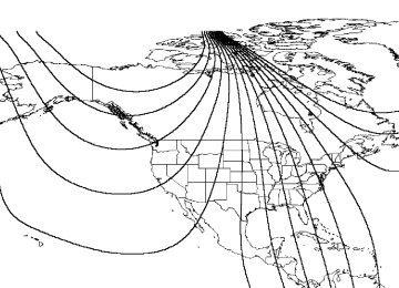
Compass zone adjustment 1. Determine which magnetic zone you are in by referring to the zone map. 2. Turn the ignition to the ON position.
Driver Controls
23
15
14
13
127 8 9 1011
3. Press and hold the SELECT control until VAR appears in the display, then release. The display should show the current zone number. 4. Press the SELECT control until the desired zone number appears. The display will flash and then return to normal operation. The zone is now updated.
9 VAR
Compass calibration adjustment Perform this adjustment in an open area free from steel structures and high voltage lines: • Press and hold the SELECT control until CAL appears in the display (approximately eight seconds) and release. • Drive the vehicle slowly (less
than 5 km/h [3 mph]) in circles until CAL indicator turns off in about 2–3 complete circles.
• The compass is now calibrated.
CAL
95
Driver Controls
CARGO ORGANIZER (IF EQUIPPED) Your vehicle comes equipped with a cargo organizer located on the floor of the cargo area. • To open, lift the cargo organizer up to the upright position, pull the front panel away from the rear panel sliding it to the right until it locks.
• To close, press the release button, slide the front panel towards the rear panel and fold down to the stowed position.
• To remove, lift the cargo
organizer up to the upright position, unscrew the screw caps on each side of the organizer and remove.
This cargo organizer is not designed to restrain objects during a collision.
96
Locks and Security
KEYS The key operates all locks on your vehicle. In case of loss, replacement keys are available from your dealer. You should always carry a second key with you in a safe place in case you require it in an emergency.
POWER DOOR LOCKS (IF EQUIPPED) Press U to unlock all doors and L to lock all doors.
Memory lock If you lock your doors with the power lock switch or the remote transmitter while the sliding door is open, the door will automatically lock after it is closed.
Back cargo door lock (if equipped) The passenger side rear cargo door has a power door lock control mounted on the inside of the door. When this lock is pressed, all doors will lock/unlock.
REMOTE ENTRY SYSTEM (IF EQUIPPED) This device complies with part 15 of the FCC rules and with RS-210 of Industry Canada. Operation is subject to the following two conditions: (1) This device may not cause harmful interference, and (2) This device must accept any interference received, including interference that may cause undesired operation.
97
Locks and Security
Changes or modifications not expressly approved by the party responsible for compliance could void the user’s authority to operate the equipment. The remote entry system allows you to lock or unlock all vehicle doors without a key. The remote entry features only operate with the ignition in the LOCK position. If there is any potential remote keyless entry problem with your vehicle, ensure ALL remote entry transmitters are brought to the dealership, to aid in troubleshooting.
Unlocking the doors Press this control to unlock the driver’s door. The interior lamps will illuminate. Press the control a second time within three seconds to unlock all doors.
Locking the doors Press this control to lock all doors. To confirm all doors are closed and locked, press the control a second time within three seconds. The doors will lock again and the horn will chirp.
98
Locks and Security
Sounding a panic alarm Press this control to activate the alarm. To deactivate the alarm, press the control again or turn the ignition to ACC or ON.
Replacing the battery The transmitter is powered by one coin type three-volt lithium battery CR2032 or equivalent. Typical operating range will allow you to be up to 10 meters (33 feet) away from your vehicle. A decrease in operating range can be caused by: • Weather conditions • Nearby radio towers • Structures around the vehicle • Other vehicles parked next to the vehicle To replace the battery: 1. Twist a thin coin between the two halves of the transmitter near the key ring. DO NOT TAKE THE FRONT PART OF THE TRANSMITTER APART. 2. Place the positive (+) side of new battery UP. Refer to the diagram inside the transmitter unit. 3. Snap the two halves back together.
Replacement of the battery will not cause the remote transmitter to become deprogrammed from your vehicle. The remote transmitter should operate normally after battery replacement.
99
Locks and Security
Replacing lost transmitters • Take all your vehicle’s
transmitters to your dealer if service is required.
• If you purchase additional transmitters (up to four may be programmed into memory), perform the following procedure.
To reprogram the transmitters yourself, place the key in the ignition and turn from 2 (LOCK) to 3 (OFF) and cycle between 3 (OFF) and 4(ON) eight times in rapid succession (within 10 seconds) ending in the ON position. After doors lock/unlock, press any control on all transmitters (up to four). With each control press of the transmitters, the door should cycle (lock/unlock) to confirm programming. When completed, turn the ignition to OFF. The door locks should cycle (lock/unlock) one last time to confirm completion of programming. All transmitters must be programmed at the same time.
Illuminated entry The interior lamps illuminate when the remote entry system is used to unlock the door(s) or sound the personal alarm. The system automatically turns off after 25 seconds or when the ignition is turned to the RUN or ACC position. The dome lamp control (if equipped) must not be set to the OFF position for the illuminated entry system to operate. The inside lights will not turn off if: • they have been turned on with the dimmer control, or • any door is open.
100
Seating and Safety Restraints
SEATING
Adjusting the front manual seat
Never adjust the driver’s seat or seatback when the vehicle is moving.
Do not pile cargo higher than the seatbacks to reduce the risk of injuring people in a collision or sudden stop.
Always drive and ride with your seatback upright and the lap belt snug and low across the hips.
Reclining the seatback can cause an occupant to slide under the seat’s safety belt, resulting in severe personal injuries in the
event of a collision.
Lift handle to move seat forward or backward.
101
Seating and Safety Restraints
Pull lever up to adjust seatback.
Using the manual lumbar support The lumbar support control is located on the inboard side of the driver’s seat. Turn the lumbar support control clockwise to increase firmness. Turn the lumbar support control counterclockwise to increase softness.
Adjusting the front power seat (if equipped)
Never adjust the driver’s seat or seatback when the vehicle is moving.
Do not pile cargo higher than the seatbacks to avoid injuring people in a collision or sudden stop.
Always drive and ride with your seatback upright and the lap belt snug and low across the hips.
Reclining the seatback can cause an occupant to slide under the seat’s safety belt, resulting in severe personal injuries in the
event of a collision.
102
Seating and Safety Restraints
The control is located on the outboard side of the seat cushion. Press to raise or lower the front portion of the seat cushion.
Press to raise or lower the rear portion of the seat cushion.
Press the control to move the seat forward, backward, up or down.
103
Seating and Safety Restraints
Quick release captains chair To remove the seat: 1. Disengage the lap/shoulder belt from the seat by inserting a key or small screwdriver into the slot in the detachable anchor and lifting upward.
Stow the tongue end of the detachable anchor.
104
Seating and Safety Restraints
2. Pull the seat latch handle, then pull the seat toward the right side of the vehicle to disengage four pins from the floor mount. 3. Remove the seat.
To install the seat:
Check to see that the seat and seatback is latched securely in position. Keep floor area free of objects that would prevent
proper seat engagement. Never attempt to adjust the seat while the vehicle is in motion.
1. Position the seat to the floor mount. 2. Engage the four pins into the floor mount hole and push the seat toward the left side of the vehicle to fully engage.
3. Pull the seat latch handle downward to lock the seat in position. 4. Make sure the safety belt is not twisted, then insert the seat belt tongue into detachable anchor until you hear a “click” and feel the latch engage.
105
Seating and Safety Restraints
ACCESSING THE 3RD, 4TH AND 5TH ROW SEATS (IF EQUIPPED) Stow the 2nd row passenger side seat belt on the overhead hook to make access to the rear seats easier.
To make access to the 4th and 5th row seats easier, attach the 3rd and 4th row passenger side seat belts to the trim panel by using the snaps attached to the seat belt webbing and the trim panel.
106
Seating and Safety Restraints
REAR BENCH SEAT To remove the seats: 1. Disengage the lap/shoulder belt from the seat by inserting a key or small screwdriver into the slot in the detachable anchor and lifting upward (2nd row passenger side only).
Stow the tongue end of the detachable anchor (2nd row only).
107
Seating and Safety Restraints
2. Pull the LH/RH seat latch handles, located under the seat, rearward to release the latch hook ends from the front strikers.
3. Move the seat rearward and lift the seats rear hooks away from the rear strikers prior to lifting the front hooks out from the front strikers. 4. With assistance, remove the seat assembly. • To remove the 3rd, 4th, and 5th row seats (if equipped), repeat steps
2 through 4.
To install the seat: 1. Position the seat in the vehicle. 2. Align front hooks to front strikers, prior to lowering the rear hooks and aligning them with the rear strikers. 3. Engage the LH/RH latch rod hook ends in the front striker locking holes. 4. Rotate the LH/RH latch handles forward, and at the same time slide the seat assembly forward to engage the strikers. Continue forward movement until the seat reaches the end of its travel. 5. Make sure the safety belt is not twisted, then insert the seat belt tongue into detachable anchor until you hear a “click” and feel the latch engage (2nd row only).
Always latch the vehicle seat to the floor, whether the seat is occupied or empty. If not latched, the seat may cause injury
during a sudden stop.
108
Seating and Safety Restraints
SAFETY RESTRAINTS Safety restraints precautions
Always drive and ride with your seatback upright and the lap belt snug and low across the hips.
To reduce the risk of injury, make sure children sit where they can be properly restrained.
Never let a passenger hold a child on his or her lap while the vehicle is moving. The passenger cannot protect the child from
injury in a collision.
All occupants of the vehicle, including the driver, should always properly wear their safety belts, even when an air bag (SRS) is
provided.
It is extremely dangerous to ride in a cargo area, inside or outside of a vehicle. In a collision, people riding in these areas
are more likely to be seriously injured or killed. Do not allow people to ride in any area of your vehicle that is not equipped with seats and safety belts. Be sure everyone in your vehicle is in a seat and using a safety belt properly.
In a rollover crash, an unbelted person is significantly more likely to die than a person wearing a safety belt.
Each seating position in your vehicle has a specific safety belt assembly which is made up of one buckle and one tongue that
are designed to be used as a pair. 1) Use the shoulder belt on the outside shoulder only. Never wear the shoulder belt under the arm. 2) Never swing the safety belt around your neck over the inside shoulder. 3) Never use a single belt for more than one person.
Always transport children 12 years old and under in the back seat and always properly use appropriate child restraints.
109
Seating and Safety Restraints
Safety belts and seats can become hot in a vehicle that has been closed up in sunny weather; they could burn a small child. Check
seat covers and buckles before you place a child anywhere near them.
Combination lap and shoulder belts 1. Insert the belt tongue into the proper buckle (the buckle closest to the direction the tongue is coming from) until you hear a snap and feel it latch. Make sure the tongue is securely fastened in the buckle.
2. To unfasten, push the release button and remove the tongue from the buckle.
The front and rear outboard safety restraints in the vehicle are combination lap and shoulder belts. The front passenger and rear seat outboard safety belts have two types of locking modes described below:
Vehicle sensitive mode The vehicle sensitive mode is the normal retractor mode, allowing free shoulder belt length adjustment to your movements and locking in response to vehicle movement. For example, if the driver brakes suddenly or turns a corner sharply, or the vehicle receives an impact of approximately 8 km/h (5 mph) or more, the combination safety belts will lock to help reduce forward movement of the driver and passengers.
110
Seating and Safety Restraints
Automatic locking mode In this mode, the shoulder belt is automatically pre-locked. The belt will still retract to remove any slack in the shoulder belt. The automatic locking mode is not available on the driver safety belt. When to use the automatic locking mode • Any time a child safety seat is installed in a passenger front or outboard rear seating position (if equipped). Children 12 years old and under should be properly restrained in the rear seat whenever possible. Refer to Safety Restraints for Children or Safety Seats for Children later in this chapter.
How to use the automatic locking mode • Buckle the combination lap and
shoulder belt.
• Grasp the shoulder portion and pull downward until the entire belt is extracted.
• Allow the belt to retract. As the belt retracts, you will hear a clicking sound. This indicates the safety belt is now in the automatic locking mode.
111
Seating and Safety Restraints
How to disengage the automatic locking mode Disconnect the combination lap/shoulder belt and allow it to retract completely to disengage the automatic locking mode and activate the vehicle sensitive (emergency) locking mode.
Ford recommends that all safety belt assemblies and attaching hardware should be inspected by a qualified technician after any collision. Safety belt assemblies not in use during a collision should also be inspected and replaced if either damage or improper operation is noted.
After any vehicle collision, the front passenger and rear outboard seat belt systems must be checked by a qualified technician to verify that the “automatic locking retractor” feature for child seats is still functioning properly. In addition, all seat belts should be checked for proper function.
BELT AND RETRACTOR ASSEMBLY MUST BE REPLACED if the seat belt assembly “automatic locking retractor” feature or any other seat belt function is not operating properly when checked according to the procedures in Workshop Manual.
Failure to replace the Belt and Retractor assembly could increase the risk of injury in collisions.
Safety belt pretensioner Your vehicle is equipped with safety belt pretensioners at the driver and front passenger seating positions. The safety belt pretensioner is a device which removes excess webbing from the safety belt system. The safety belt pretensioner uses the same crash sensor system as the front air bag supplemental restraint system (SRS). When the safety belt pretensioner deploys, webbing from the lap and shoulder belt is tightened. The driver and front passenger seat belt system (including retractors, buckles and height adjusters) must be