- Download PDF Manual
-
Whenever the vehicle is hoisted, all steering linkage joints should be inspected for evidence of damage. If seals are damaged, parts should be replaced to prevent
MAINTAINING YOUR VEHICLE 465
leakage or contamination of the grease. Lubricate the steering linkage regularly according to the “Maintenance Schedule” in this manual. Half-shaft Constant Velocity Joints All four- wheel- drive 1500 models are equipped with four constant velocity joints. Periodic lubrication of these joints is not required. However, the joint boots should be inspected for external leakage or damage periodically. If external leakage or damage is evident, the joint boot and grease should be replaced immediately. Continued op- eration could result in failure of the joint due to water and dirt contamination of the grease. This would require complete replacement of the joint assembly. Refer to the Service Manual for the detailed replacement procedure.
466 MAINTAINING YOUR VEHICLE
Front Prop Shaft Lubrication — 2500/3500 (4X4) Models Lubricate the front driveshaft grease fitting at each oil change listed in the appropriate Maintenance Schedule for your vehicle (Schedule “A” and “B”). Use Mopar威 type MS-6560 (lithium based grease), or equivalent.
Front Driveshaft Grease Fitting
Body Lubrication Locks and all body pivot points, including such items as seat tracks, doors, tailgate and hood hinges, should be lubricated periodically to assure quiet, easy operation and to protect against rust and wear. Prior to the appli- cation of any lubricant, the parts concerned should be wiped clean to remove dust and grit; after lubricating excess oil and grease should be removed. Particular attention should also be given to hood latching compo- nents to insure proper function. When performing other underhood services, the hood latch, release mechanism and safety catch should be cleaned and lubricated. The external lock cylinders should be lubricated twice a year, preferably in the fall and spring. Apply a small amount of a high quality lubricant such as Mopar威 Lock Cylinder Lubricant directly into the lock cylinder.
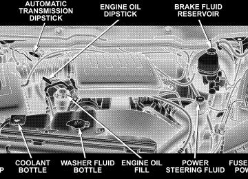
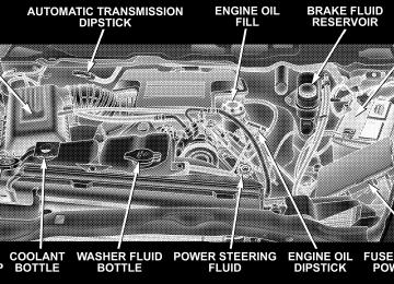
Windshield Wiper Blades The rubber edges of the wiper blades and the windshield should be cleaned periodically with a sponge or soft cloth and a mild nonabrasive cleaner. This will remove accu- mulations of salt or road film. Operation of the wipers on dry glass for long periods may cause deterioration of the wiper blades. Always use washer fluid when using the wipers to remove salt or dirt from a dry windshield. Avoid using the wiper blades to remove frost or ice from the windshield. Keep the blade rubber out of contact with petroleum products such as engine oil, gasoline, etc. Windshield Washers The fluid reservoir is located under the hood and should be checked for fluid level at regular intervals. Fill the
MAINTAINING YOUR VEHICLE 467
reservoir with windshield washer solvent only (not ra- diator antifreeze). When refilling the washer fluid reser- voir, take some washer fluid and apply it to a cloth or towel and wipe clean the wiper blades, this will help blade performance. To prevent freeze-up of your windshield washer system in cold weather, select a solution or mixture that meets or exceeds the temperature range of your climate. This rating information can be found on most washer fluid containers.
WARNING!
Commercially available windshield washer solvents are flammable. They could ignite and burn you. Care must be exercised when filling or working around the washer solution.
468 MAINTAINING YOUR VEHICLE
After the engine has warmed, operate the defroster for a few minutes to reduce the possibility of smearing or freezing the fluid on the cold windshield. Mopar All Weather Windshield Washer Solution, used with water as directed on the container, aids cleaning action, reduces the freezing point to avoid line clogging, and is not harmful to paint or trim. Exhaust System The best protection against carbon monoxide entry into the vehicle body is a properly maintained engine exhaust system. Whenever a change is noticed in the sound of the exhaust system, when exhaust fumes can be detected inside the vehicle, or when the underside or rear of the vehicle is damaged, have a competent mechanic inspect the com- plete exhaust system and adjacent body areas for broken, damaged, deteriorated, or mispositioned parts. Open seams or loose connections could permit exhaust fumes
to seep into the passenger compartment. In addition, inspect the exhaust system each time the vehicle is raised for lubrication or oil change. Replace as required.
WARNING!
Exhaust gases can injure or kill. They contain carbon monoxide (CO) which is colorless and odorless. Breathing it can make you unconscious and can eventually poison you. To avoid breathing CO, refer to Exhaust Gas in the Safety Tips section of this manual.
Exhaust System Rubber Isolator and Loop-Type Hanger — If Equipped Inspect surfaces whenever the vehicle is hoisted for rubber to metal separation or deep cracks. SLIGHT
CRACKING DUE TO WEATHERING DOES NOT AD- VERSELY AFFECT PERFORMANCE. If, however, exces- sively deep localized cracks are present, or any part of the exhaust system abnormally contacts the underbody hard- ware, the isolator and/or hanger should be replaced. Cooling System
WARNING!
You or others can be badly burned by hot coolant or steam from your radiator. If you see or hear steam coming from under the hood, don’t open the hood until the radiator has had time to cool. Never try to open a cooling system pressure cap when the radia- tor is hot.
MAINTAINING YOUR VEHICLE 469
Engine Coolant Checks Check the engine coolant (antifreeze) protection every 12
months (before the onset of freezing weather, where applicable). If coolant is dirty or rusty in appearance, the system should be drained, flushed and refilled with fresh coolant. Check the front of the A/C condenser for any accumulation of bugs, leaves, etc. If dirty, clean by gently spraying water from a garden hose vertically down the face of the condenser. Check the coolant recovery bottle tubing for brittle rub- ber, cracking, tears, cuts and tightness of the connection at the bottle and radiator. Inspect the entire system for leaks. With the engine at normal operating temperature (but not running), check the cooling system pressure cap for proper vacuum sealing by draining a small amount of coolant from the radiator drain cock. If the cap is sealing properly, the engine coolant (antifreeze) will begin to470 MAINTAINING YOUR VEHICLE
drain from the coolant recovery bottle. DO NOT RE- MOVE THE COOLANT PRESSURE CAP WHEN THE COOLING SYSTEM IS HOT. Cooling System — Drain, Flush and Refill At the intervals shown on the Maintenance Schedules, the system should be drained, flushed and refilled. If the solution is dirty or contains a considerable amount of sediment, clean and flush with a reliable cooling system cleaner. Follow with a thorough rinsing to remove all deposits and chemicals. Properly dispose of old antifreeze solution. Selection Of Coolant Use only the manufacturers recommended coolant, refer to Fluids, Lubricants and Genuine Parts for correct coolant type.
CAUTION!
Mixing of coolants other than specified HOAT en- gine coolants, may result in engine damage and may decrease corrosion protection. If a non-HOAT cool- ant is introduced into the cooling system in an emergency, it should be replaced with the specified coolant as soon as possible. Do not use plain water alone or alcohol base engine coolant (antifreeze) products. Do not use additional rust inhibitors or antirust products, as they may not be compatible with the radiator engine coolant and may plug the radiator. This vehicle has not been designed for use with Propylene Glycol based coolants. Use of Propylene Glycol based coolants is not recommended.
Adding Coolant Your vehicle has been built with an improved engine coolant that allows extended maintenance intervals. This coolant can be used up to 5 Years or 100,000 miles before replacement. To prevent reducing this extended mainte- nance period, it is important that you use the same coolant throughout the life of your vehicle. Please review these recommendations for using Hybrid Organic Addi- tive Technology (HOAT) coolant. When adding coolant, a minimum solution of 50% rec- ommended Mopar Antifreeze/ Coolant 5 Year/100,000
Mile Formula HOAT (Hybrid Organic Additive Technol- ogy), or equivalent, in water should be used. Use higher concentrations (not to exceed 70%) if temperatures below ⫺34°F (⫺37°C ) are anticipated. Use only high purity water such as distilled or deionized water when mixing the water/engine coolant solution.MAINTAINING YOUR VEHICLE 471
The use of lower quality water will reduce the amount of corrosion protection in the engine cooling system. Please note that it is the owner’s responsibility to main- tain the proper level of protection against freezing ac- cording to the temperatures occurring in the area where the vehicle is operated. NOTE: Mixing coolant types will decrease the life of the engine coolant and will require more frequent coolant changes. Cooling System Pressure Cap The cap must be fully tightened to prevent loss of coolant, and to insure that coolant will return to the radiator from the coolant recovery bottle. The cap should be inspected and cleaned if there is any accumulation of foreign material on the sealing surfaces.
472 MAINTAINING YOUR VEHICLE
WARNING!
• The warning words “DO NOT OPEN HOT” on the cooling system pressure cap are a safety pre- caution. Never add coolant when the engine is overheated. Do not loosen or remove the cap to cool an overheated engine. Heat causes pressure to build up in the cooling system. To prevent scalding or injury, do not remove the pressure cap while the system is hot or under pressure. • Do not use a pressure cap other than the one specified for your vehicle. Personal injury or engine damage may result.
Disposal of Used Engine Coolant Used ethylene glycol based engine coolant is a regulated substance requiring proper disposal. Check with your local authorities to determine the disposal rules for your community. To prevent ingestion by animals or children
do not store ethylene glycol based engine coolant in open containers or allow it to remain in puddles on the ground. If ingested by a child, contact a physician immediately. Clean up any ground spills immediately. Coolant Level The coolant bottle provides a quick visual method for determining that the coolant level is adequate. With the engine cold, the level of the coolant in the coolant recovery bottle should be between the ranges indicated on the bottle. The radiator normally remains completely full, so there is no need to remove the radiator cap unless checking for coolant freeze point or replacing coolant. Advise your service attendant of this. As long as the engine operating temperature is satisfactory, the coolant bottle need only be checked once a month.
When additional coolant is needed to maintain the proper level, it should be added to the coolant bottle. Do not overfill. Points To Remember NOTE: When the vehicle is stopped after a few miles (a few kilometers) of operation, you may observe vapor coming from the front of the engine compartment. This is normally a result of moisture from rain, snow, or high humidity accumulating on the radiator and being vapor- ized when the thermostat opens, allowing hot coolant to enter the radiator. If an examination of your engine compartment shows no evidence of radiator or hose leaks, the vehicle may be safely driven. The vapor will soon dissipate. • Do not overfill the coolant recovery bottle.
MAINTAINING YOUR VEHICLE 473
• Check coolant freeze point in the radiator and in the coolant recovery bottle. If antifreeze needs to be added, contents of coolant recovery bottle must also be protected against freezing. • If frequent coolant additions are required, or if the level in the coolant recovery bottle does not drop when the engine cools, the cooling system should be pres- sure tested for leaks. • Maintain coolant concentration at 50% HOAT engine coolant (minimum) and distilled water for proper corrosion protection of your engine which contains aluminum components. • Make sure that the radiator and coolant recovery bottle overflow hoses are not kinked or obstructed. • Keep the front of the radiator clean. If your vehicle is equipped with air conditioning, keep the front of the condenser clean, also.
474 MAINTAINING YOUR VEHICLE
• Do not change the thermostat for summer or winter operation. If replacement is ever necessary, install ONLY the correct type thermostat. Other designs may result in unsatisfactory coolant performance, poor gas mileage, and increased emissions.
Hoses And Vacuum/Vapor Harnesses Inspect surfaces of hoses and nylon tubing for evidence of heat and mechanical damage. Hard or soft spots, brittle rubber, cracking, tears, cuts, abrasions, and exces- sive swelling indicate deterioration of the rubber. Pay particular attention to those hoses nearest to high heat sources such as the exhaust manifold. Inspect hose routing to be sure hoses do not come in contact with any heat source or moving component which may cause heat damage or mechanical wear. Insure nylon tubing in these areas has not melted or collapsed.
Inspect all hose connections such as clamps and cou- plings to make sure they are secure and no leaks are present. Components should be replaced immediately if there is any evidence of wear or damage that could cause failure. Fuel System Connections Electronic Fuel Injection high pressure fuel systems are designed with tubes and special connects, connections and clamps which have unique material characteristics to provide adequate sealing and resist attack by deterio- rated gasoline. You are urged to use only the manufactures-specified tubes, connections and clamps, or their equivalent in material and specification, in any fuel system servicing.
Brake System
Power Disc Brakes (front and rear) Disc brakes do not require adjustment; however, several hard stops during the break-in period are recommended to seat the linings and wear off any foreign material. Brake And Power Steering Hoses When the vehicle is serviced for scheduled maintenance, inspect surface of hoses and nylon tubing for evidence of heat and mechanical damage. Hard and brittle rubber, cracking, tears, cuts, abrasion, and excessive swelling indicate deterioration of the rubber. Particular attention should be made to examining those hose surfaces nearest to high heat sources, such as the exhaust manifold. Insure nylon tubing in these areas has not melted or collapsed.
MAINTAINING YOUR VEHICLE 475
Inspect all hose connections such as clamps and cou- plings to make sure they are secure and no leaks are present. NOTE: Often, fluid such as oil, power steering fluid, and brake fluid are used during assembly plant opera- tions to facilitate the assembly of hoses to couplings. Therefore, oil wetness at the hose-coupling area is not necessarily an indication of leakage. Actual dripping of hot fluid when systems are under pressure (during vehicle operation), should be noted before hose is re- placed based on leakage. Inspection of brake hoses should be performed NOTE: whenever the brake system is serviced and every engine oil change. Inspect hydraulic brake hoses for surface cracking, scuffing, or worn spots. If there is any evidence of cracking, scuffing, or worn spots, the hose should be replaced immediately! Eventual deterioration of the hose can take place resulting in a possibility of a burst failure.
476 MAINTAINING YOUR VEHICLE
WARNING!
Worn brake hoses can burst and cause brake failure. You could have an accident. If you see any signs of cracking, scuffing, or worn spots, have the brake hoses replaced immediately.
Brake Master Cylinder — Brake Fluid Level Check The fluid level of the master cylinder should be checked when performing under the hood service, or immedi- ately if the brake system warning lamp indicates system failure. The brake master cylinder has a translucent plastic reservoir. On the outboard side of the reservoir, there is a “MAX” dot and an “MIN” dot. The fluid level must be kept within these two dots. Do not add fluid above the MAX mark, because leakage may occur at the cap.
With disc brakes the fluid level can be expected to fall as the brake linings wear. However, an unexpected drop in fluid level may be caused by a leak and a system check should be conducted. Refer to Fluids, Lubricants and Genuine Parts for the correct Fluid type.
WARNING!
Use of a brake fluid that may have a lower initial boiling point, or is unidentified as to specification, may result in sudden brake failure during hard prolonged braking. You could have an accident.
WARNING!
Clutch Hydraulic System
MAINTAINING YOUR VEHICLE 477
Overfilling the brake fluid reservoir can result in spilling brake fluid on hot engine parts and the brake fluid catching fire.
Use only brake fluid that has been in a tightly closed container to avoid contamination from foreign matter or moisture.
CAUTION!
Do not allow a petroleum-base fluid to contaminate the brake fluid. Seal damage may result.
The clutch hydraulic system is a sealed maintenance-free system. In the event of leakage or other malfunction, the system must be replaced. Clutch Linkage If the clutch pedal linkage begins to squeak or grunt, the clutch pedal pivot bushings should be lubricated. Refer to Fluids, Lubricants and Genuine Parts for the correct lubricant type. Rear Axle And 4x4 Front Driving Axle Fluid Level Refer to Fluids, Lubricants and Genuine Parts for the correct Fluid type. For normal service, periodic fluid level checks are not required. When the vehicle is serviced for other reasons the exterior surfaces of the axle assembly should be inspected. If gear oil leakage is suspected inspect the fluid level.
478 MAINTAINING YOUR VEHICLE
This inspection should be made with the vehicle in a level position. The fluid level should be even with the bottom of the fill hole for the Manufacturer’s C205F HD Front Axles. The fluid level should be 5/8” (16 mm) below on 9 1/4” Manufacturer’s Rear Axles. For all 2500/3500 Model axles, the fluid level should be 1/4” ± 1/4” (6.4 mm ± 6.4 mm) below the fill hole on the 9.25” Front and 3/4”± 1/4” (19 mm ± 6.4 mm) on 10.5” Rear axles. The 11.5” Rear Axle level should be 1/4” ± 1/4” (6.4 mm ± 6.4 mm) below the fill hole. Drain and Refill Vehicles operated in normal service do not have regularly scheduled oil changes. If fluid has become contaminated with water or to provide the correct viscosity grade, drain and refill. Lubricant Selection Refer to Fluids, Lubricants and Genuine Parts for correct fluid type.
NOTE: The presence of water in the gear lubricant will result in corrosion and possible failure of differential components. Operation of the vehicle in water, as may be encountered in some off-highway types of service, will require draining and refilling the axle to avoid damage. Limited-Slip Differentials in 1500 Model vehicles re- quire that 4 oz. (118 ml) Mopar威 limited slip additive be added to the gear lubricant. Refer to Fluids, Lubricants and Genuine Parts for correct fluid type. The Mopar威 Limited Slip Additive should be added to the gear lubricant whenever a fluid change is made. Ram 2500/3500 Model Axles DO NOT REQUIRE any limited slip oil additive (friction modifiers).
Transfer Case
Fluid Level Check This fluid level can be checked by removing the filler plug. The fluid level should be to the bottom edge of the filler plug hole with the vehicle in a level position. Lubricant Selection Refer to Fluids, Lubricants and Genuine Parts for correct fluid type. Manual Transmission
Lubricant Selection G238 (6-Speed Manual Transmission — If Equipped) This transmission is filled with manual transmission fluid at the factory. This fluid does not require periodic changing. If it is necessary to add or change fluid in this transmission refer to Fluids, Lubricants and Genuine Parts for correct fluid type. This is the only lubricant recommended for use in the Getrag 238 transmission.
MAINTAINING YOUR VEHICLE 479
Lubricant Selection G56 (6-Speed Manual Transmission — If Equipped) This transmission is filled with manual transmission fluid at the factory. This fluid only requires periodic changing if the vehicle is operated under severe condi- tions as defined under Maintenance Schedule ”B” in the Maintenance Schedule section of this Owner’s Manual. If it is necessary to add or change fluid in this transmission refer to Fluids, Lubricants and Genuine Parts for correct fluid type. This is the only lubricant recommended for use in the G56 transmission. Fluid Level Check – All Manual Transmissions This fluid level can be checked by removing the fill plug. If the level of the lubricant is more than 1/4” (6.4 mm) below the bottom of the filler hole while the vehicle is on level ground, enough lubricant should be added to bring the level to the bottom of the filler hole.
480 MAINTAINING YOUR VEHICLE
Automatic Transmission
Selection Of Lubricant Refer to Fluids, Lubricants and Genuine Parts for correct fluid type. It is important that the transmission fluid be maintained at the prescribed level using the recom- mended fluid.
CAUTION!
Using a transmission fluid other than the manufac- turers recommended fluid may cause deterioration in transmission shift quality and/or torque converter shudder. Using a transmission fluid other than the manufacturers recommended fluid will result in more frequent fluid and filter changes. Refer to Fluids, Lubricants and Genuine Parts for correct fluid type.
Fluid Level Check The fluid level should be checked when the engine is fully warmed up and the fluid in the transmission is at normal operating temperature. Operation of the trans- mission with an improper fluid level will greatly reduce the life of the transmission and of the fluid. Check the fluid level whenever the vehicle is serviced. Fluid Level Check – 545RFE/42RLE Check the fluid level while the transmission is at normal operating temperature 82°C (180°F). This occurs after at least 15 miles (25 km) of driving. At normal operating temperature the fluid cannot be held comfortably be- tween the fingertips.
To check the automatic transmission fluid level properly, the following procedure must be used: 1. Operate the engine at idle speed and normal operating temperature. 2. The vehicle must be on level ground. 3. Fully apply the parking brake and press the brake pedal. 4. Place the gear selector momentarily in each gear position ending with the lever in P (Park). 5. Remove the dipstick, wipe it clean and reinsert it until seated. 6. Remove the dipstick again and note the fluid level on both sides. The fluid level should be between the “HOT” (upper) reference holes on the dipstick at normal operat- ing temperature. Verify that solid coating of oil is seen on both sides of the dipstick. If the fluid is low, add as
MAINTAINING YOUR VEHICLE 481
required into the dipstick tube. Do not overfill. After adding any quantity of oil through the oil fill tube, wait a minimum of two (2) minutes for the oil to fully drain into the transmission before rechecking the fluid level. If it is necessary to check the transmission below NOTE: the operating temperature, the fluid level should be between the two “COLD” (lower) holes on the dipstick with the fluid at approximately 70°F (21°C) (room tem- perature). If the fluid level is correctly established at room temperature, it should be between the “HOT” (upper) reference holes when the transmission reaches 180°F (82°C). Remember it is best to check the level at the normal operating temperature.
482 MAINTAINING YOUR VEHICLE
CAUTION!
Be aware that if the fluid temperature is below 50°F (10°C) it may not register on the dipstick. Do not add fluid until the temperature is elevated enough to produce an accurate reading.
7. Check for leaks. Release parking brake. To prevent dirt and water from entering the transmission after checking or replenishing fluid, make certain that the dipstick cap is properly reseated. It is normal for the dipstick cap to spring back slightly from its fully seated position, as long as its seal remains engaged in the dipstick tube. Automatic Transmission Fluid and Filter Change It is important that proper lubricant is used in the transmission. Refer to Fluids, Lubricants and Genuine Parts for correct fluid type.
If the transmission is disassembled for any
The fluid and filter(s) should be changed as specified in the Maintenance Schedule (Section 8). NOTE: reason, the fluid and filter(s) should be changed. Special Additives The manufacturer strongly recommends against the ad- dition of any additives to the transmission. Exception to this policy is the use of special dyes to aid in detecting fluid leaks. The use of transmission sealers should be avoided, since they may adversely affect seals. Front and rear Wheel Bearings
Front Wheel Bearings Front wheel bearings for all Dodge Ram Trucks are sealed-for-life. They do not require greasing or seal replacement. these bearings will
In some instances,
“purge” excess grease and the bearing will look slightly wet. This is normal. Periodic inspection for excess play is recommended. Rear Wheel Bearings — Manufacturer’s Axles These bearings are normally considered permanently lubricated. Cleaning and repacking is required only when axle shafts are removed or in case of extreme water or dust contamination. Noise Control System Required Maintenance & Warranty For 3500 2-Wheel Drive and 4-Wheel Drive models over 10,000 lbs. (4 535 kg) Gross Vehicle Weight Rating. All vehicles built over 10,000 lbs (4 535 kg) Gross Vehicle Weight Rating and manufactured for sale and use in the United States are required to comply with the Federal Government’s Exterior Noise Regulations. These vehicles
MAINTAINING YOUR VEHICLE 483
can be identified by the Noise Emission Control Label located in the operator’s compartment.
Required Maintenance for Noise Control Systems The following maintenance services must be performed every 6 months or 6,000 miles (9 600 km), whichever comes first, to assure proper operation of the noise control systems. inspection and service
In addition,
484 MAINTAINING YOUR VEHICLE
should be performed anytime a malfunction is observed or suspected. Proper maintenance of the entire vehicle will help the effectiveness of the noise control systems. Air Cleaner Assembly Inspect air cleaner housing for proper assembly and fit. Make certain that the air cleaner is properly positioned and the cover is tight. Check all hoses leading to the cleaner for tightness. The gasket between the air cleaner housing and throttle body must be intact and in good condition. The engine air cleaner filter must also be clean and serviced according to the instructions outlined in the appropriate maintenance schedule. Tampering with Noise Control System Prohibited Federal law prohibits the following acts or the causing thereof: (1) the removal or rendering inoperative by any person, other than for purposes of maintenance, repair, or replacement, of any device or element of design incorpo- rated into any new vehicle for the purpose of noise
control prior to its sale or delivery to the ultimate purchaser or while it is in use, or (2) the use of the vehicle after such device or element of design has been removed or rendered inoperative by any person. Among those acts presumed to constitute tampering are the acts listed below. AIR CLEANER • Removal of the air cleaner. • Inverting the air cleaner lid. • Removal of the air ducting. EXHAUST SYSTEM • Removal or rendering inoperative exhaust system
components including the muffler or tailpipe.
ENGINE COOLING SYSTEM • Removal or rendering inoperative the fan clutch. • Removal of the fan shroud. Noise Emission Warranty The manufacturer warrants that this vehicle as manufac- tured by the manufacturer, was designed, built and equipped to conform at the time it left the manufacturers control with all applicable U.S. EPA Noise Control Regu- lations.
MAINTAINING YOUR VEHICLE 485
This warranty covers this vehicle as designed, built and equipped by the manufacturer, and is not limited to any particular part, component or system of the vehicle manufactured by the manufacturer. Defects in design, assembly or in any part, component or system of the vehicle as manufactured by the manufacturer, which, at the time it left the manufacturers control, caused noise emissions to exceed Federal standards, are covered by this warranty for the life of the vehicle.
486 MAINTAINING YOUR VEHICLE
Noise Systems Maintenance Chart and Service Log Insert Month, Day, Year under column mileage closest to the mileage at which service was performed. MILES KILOMETERS Exhaust system-inspect Air cleaner assembly-inspect ODOMETER READING PERFORMED BY PERFORMED AT
24,000
39 00030,000
48 00036,000
58 00048,000
77 0006,000
10 00018,000
29 00012,000
19 00042,000
68 00054,000
87 00060,000
97 00066,000
106 00072,000
116 00078,000
126 00084,000
135 00090,000
145 00096,000
154 000MILES KILOMETERS Exhaust system-inspect Air cleaner assembly-inspect ODOMETER READING PERFORMED BY PERFORMED AT
Appearance Care and Protection from Corrosion
Protection of Body and Paint from Corrosion Vehicle body care requirements vary according to geo- graphic locations and usage. Chemicals that make roads passable in snow and ice, and those that are sprayed on trees and road surfaces during other seasons, are highly corrosive to the metal in your vehicle. Outside parking, which exposes your vehicle to airborne contaminants, road surfaces on which the vehicle is operated, extreme hot or cold weather and other extreme conditions will have an adverse effect on paint, metal trim, and under- body protection. The following maintenance recommendations will enable you to obtain maximum benefit from the corrosion resistance built into your vehicle.
MAINTAINING YOUR VEHICLE 487
What Causes Corrosion? Corrosion is the result of deterioration or removal of paint and protective coatings from your vehicle. The most common causes are: • Road salt, dirt and moisture accumulation. • Stone and gravel impact. • Insects, tree sap and tar. • Salt in the air near seacoast localities. • Atmospheric fallout/industrial pollutants.
488 MAINTAINING YOUR VEHICLE
Washing • Wash your vehicle regularly. Always wash your ve- hicle in the shade using Mopar Car Wash or a mild car wash soap, and rinse the panels completely with clear water. • If insects, tar or other similar deposits have accumu- lated on your vehicle, use Mopar Super Kleen Bug and Tar Remover to remove. • Use Mopar Cleaner Wax to remove road film, stains and to protect your paint finish. Take care never to scratch the paint. • Avoid using abrasive compounds and power buffing that may diminish the gloss or thin out the paint finish.
CAUTION!
Do not use abrasive or strong cleaning materials such as steel wool or scouring powder, which will scratch metal and painted surfaces.
Special Care • If you drive on salted or dusty roads or if you drive near the ocean, hose off the undercarriage at least once a month. • It is important that the drain holes in the lower edges of the doors, rocker panels and trunk be kept clear and open. • If you detect any stone chips or scratches in the paint, touch them up immediately. The cost of such repairs is considered the responsibility of the owner.
• If your vehicle is damaged due to an accident or similar cause which destroys the paint and protective coating, have your vehicle repaired as soon as pos- sible. The cost of such repairs is considered the respon- sibility of the owner. • If you carry special cargo such as chemicals, fertilizers, de-icer salt, etc., be sure that such materials are well packaged and sealed. • If a lot of driving is done on gravel roads, consider • Use Mopar touch up paint on scratches as soon as possible. Your dealer has touch up paint to match the color of your vehicle.
mud or stone shields behind each wheel.
MAINTAINING YOUR VEHICLE 489
Wheel and Wheel Trim Care All wheels and wheel trim, especially aluminum and chrome plated wheels should be cleaned regularly with a mild soap and water to prevent corrosion. To remove heavy soil and/or excessive brake dust, use Mopar威 Wheel Cleaner (05066247AB) or equivalent or select a nonabrasive, non-acidic cleaner. Do not use scouring pads, steel wool, a bristle brush, or metal polishes. Only Mopar威or equivalent is recommended. Do not use oven cleaner. Avoid automatic car washes that use acidic solutions or harsh brushes that may damage the wheels’ protective finish.
490 MAINTAINING YOUR VEHICLE
Interior Care Use Mopar Total Clean to clean fabric upholstery and carpeting. Use Mopar Total Clean to clean vinyl upholstery. Mopar Total Clean is specifically recommended for leather upholstery. Your leather upholstery can be best preserved by regular cleaning with a damp soft cloth. Small particles of dirt can act as an abrasive and damage the leather upholstery and should be removed promptly with a damp cloth. Stubborn soils can be removed easily with a soft cloth and Mopar Total Clean. Care should be taken to avoid soaking your leather upholstery with any liquid. Please do not use polishes, oils, cleaning fluids, solvents, deter- gents, or ammonia based cleaners to clean your leather upholstery. Application of a leather conditioner is not required to maintain the original condition.
WARNING!
Do not use volatile solvents for cleaning purposes. Many are potentially flammable, and if used in closed areas they may cause respiratory harm.
Cleaning Headlights Your vehicle has plastic headlights that are lighter and less susceptible to stone breakage than glass headlights. Plastic is not as scratch resistant as glass and therefore different lens cleaning procedures must be followed. To minimize the possibility of scratching the lenses and reducing light output, avoid wiping with a dry cloth. To remove road dirt, wash with a mild soap solution fol- lowed by rinsing. Do not use abrasive cleaning components, solvents, steel wool or other aggressive material to clean the lenses.
Glass Surfaces All glass surfaces should be cleaned on a regular basis with Mopar Glass Cleaner or any commercial household- type glass cleaner. Never use an abrasive type cleaner. Use caution when cleaning the inside rear window equipped with electric defrosters or the right rear quarter window equipped with the radio antenna. Do not use scrapers or other sharp instruments which may scratch the elements. When cleaning the rear view mirror, spray cleaner on the towel or rag that you are using. Do not spray cleaner directly on the mirror. Cleaning Plastic Instrument Cluster Lenses The lenses in front of the instruments in this vehicle are molded in clear plastic. When cleaning the lenses, care must be taken to avoid scratching the plastic.
MAINTAINING YOUR VEHICLE 491
1. Clean with a wet soft rag. A mild soap solution may be used, but do not use high alcohol content or abrasive cleaners. If soap is used, wipe clean with a clean damp rag. 2. Dry with a soft tissue. Seat Belt Maintenance Do not bleach, dye or clean the belts with chemical solvents or abrasive cleaners. This will weaken the fabric. Sun damage can also weaken the fabric. If the belts need cleaning, use a mild soap solution or lukewarm water. Do not remove the belts from the car to wash them. Replace the belts if they appear frayed or worn or if the buckles do not work properly. Dry with a soft tissue.
492 MAINTAINING YOUR VEHICLE
FUSES (INTEGRATED POWER MODULE) An integrated Power Module is located in the engine compartment near the battery. This center contains car- tridge fuses and mini fuses. A description of each fuse and component may be stamped on the inside cover otherwise the cavity number of each fuse is stamped on the inside cover that corresponds to the following chart.
Integrated Power Module Location
Cavity Cartridge
Fuse
Mini Fuse 20 Amp Yellow 20 Amp Yellow
20 Amp Yellow 15 Amp Blue 20 Amp Yellow 10 Amp Red
Description
Power Outlet Console
Cabin Compartment Node (CCN) Door Locks/Brake Trans- mission Shift Inter- lock (BTSI) Spare
Spare
Power Sunroof
Occupant Classifica- tion Module (OCM)/ VIST Fan/Wastegate
Cavity Cartridge
Fuse
10
30 Amp Pink
MAINTAINING YOUR VEHICLE 493
Mini Fuse 15 Amp Blue
10 Amp Red
5 Amp Orange
Description
Reverse Lockout Sole- noid Battery (SRT-10
Only) Heated MirrorsOff Road Module Power Trx-Off Rd Pkg Sen (Gas Engine Only)
494 MAINTAINING YOUR VEHICLE
Cavity Cartridge
Fuse
11
12
13
14
30 Amp Pink
Mini Fuse 20 Amp Yellow
25 Amp Natural
15 Amp Blue
Description
Cavity Cartridge
Fuse
Ignition Off Draw (IOD)-Cabin Com- partment Node (CCN)/Radio/Under Hood Lamp/Wireless Control Module (WCM)/Satellite Digi- tal Audio Receiver (SDARS)/Hands Free Module (HFM) Electric Brake
Power-Battery RWAL/ABS Module Feed Park Lamps Left
15
16
17
18
19
20
21
22
40 Amp Green 30 Amp Pink
Mini Fuse 20 Amp Yellow 15 Amp Blue 15 Amp Blue
10 Amp Red 10 Amp Red
2 Amp Gray
Description
Trailer Park Lamps
Park Lamps Right
Spare
ABS Pump
Trailer Tow
Occupant Restraints Controller (ORC) 2
Occupant Restraints Controller (ORC) Pre- set Carrier IGN Switch FeedCavity Cartridge
Fuse
23
24
25
26
27
28
20 Amp Blue
40 Amp Green
Mini Fuse 10 Amp Red
10 Amp Red 20 Amp Yellow
10 Amp Red
Description
Engine Control Mod- ule (ECM)/Wireless Control Module (WCM)/HVC Subwoofer Amplifier (SRT-10 Only) Power Mirror
Brake Switch/Center High Mount Stop Lamp (CHMSL) Power Seats
Power Run/Start- NCC/Wireless Con- trol Module (WCM)/ ABS/RWAL
Cavity Cartridge
Fuse
29
30
31
32
33
34
35
MAINTAINING YOUR VEHICLE 495
Mini Fuse 10 Amp Red 15 Amp Blue 10 Amp Red 10 Amp Red
10 Amp Red 10 Amp Red 15 Amp Blue
Description
Switches/EC Mirror/ Smart Bar Spare
PCM/Transfer Case Brake HVAC/Ajustable Pedals/Heated Seats Switch LED/Exhaust Brake Power-IGN Run Misc
Spare
Cabin Compartment Node (CCN) Illumi- nation
496 MAINTAINING YOUR VEHICLE
Cavity Cartridge
Fuse
Mini Fuse 25 Amp Natural 15 Amp Blue 20 Amp Yellow 10 Amp Red 20 Amp Yellow 25 Amp Natural
Description
Audio_Amplifier
Spare
Power Outlet IP
Sunroof/Seatbelt Ten- sioner Cigar Lighter
Spare
CAUTION!
• When installing the Integrated Power Module cover, it is important to ensure the cover is prop- erly positioned and fully latched. Failure to do so may allow water to get into the Integrated Power Module, and possibly result in a electrical system failure. • When replacing a blown fuse, it is important to use only a fuse having the correct amperage rating. The use of a fuse with a rating other than indicated may result in a dangerous electrical system overload. If a properly rated fuse contin- ues to blow, it indicates a problem in the circuit that must be corrected.
30 Amp Pink
Diesel PCM (Diesel Only)
36
37
38
39
40
41
42
VEHICLE STORAGE If you are storing your vehicle for more than 21 days, we recommend that you take the following steps to mini- mize the drain on your vehicle’s battery: • Disconnect the Ignition-Off Draw fuse (I.O.D.) fuse located in the Integrated Power Module, located in the engine compartment. The I.O.D. cavity includes a snap-in retainer that allows the fuse to be discon- nected, without removing it from the fuse block. • The electronic shift transfer case should be placed in the 4HI mode and kept in this position to minimize the battery drain. • As an alternative to the above steps you may, discon-
nect the negative cables from both batteries.
MAINTAINING YOUR VEHICLE 497
• Anytime you store your vehicle, or keep it out of service (i.e. vacation) for two weeks or more, run the air conditioning system at idle for about five minutes in the fresh air and high blower setting. This will insure adequate system lubrication to minimize the possibility of compressor damage when the system is started again.
NOTE: When reinstalling the IOD fuse push firmly until fully seated, the gages in the Instrument Cluster will do a full sweep, when the ignition key is cycled to RUN. This is a normal condition.
498 MAINTAINING YOUR VEHICLE
REPLACEMENT LIGHT BULBS
LIGHT BULBS — Interior Bulb No. Overhead Console Lights . . . . . . . . . . . . . . . TS 212-2
Dome Light. . . . . . . . . . . . . . . . . . . . . . . . . . . . 7679
NOTE: For lighted switches, see your dealer for replace- ment instructions. All of the inside bulbs are brass or glass wedge base. Aluminum base bulbs are not approved.LIGHT BULBS — Exterior Bulb No. Back-Up . . . . . . . . . . . . . . . . . . . . . . . . . . . . . . 3057
Center High Mounted Stop Lamp . . . . . . . . . . . . . 912
Fog Lamp . . . . . . . . . . . . . . . . . . . . . . . . . . . 9006LL Headlamp (Halogen) . . . . . . . . . . . . . . . . . . . . . H13
Side Marker, Park & Turn Signal . . . . . . . . . 3157NAK Rear License Plate Lamp . . . . . . . . . . . . . . . . . . . 168
Rear Cargo Light. . . . . . . . . . . . . . . . . . . . . . . . . 912
Tail & Stop . . . . . . . . . . . . . . . . . . . . . . . . . . . . 3057
Cab Clearance Lights . . . . . . . . . . . . . . . . . . . . . . 168
Dual Rear Wheel Sidemarker Light . . . . . . . . . . . . 168
Dual Rear Wheel Tailgate ID Lights (3) . . . . . . . . . 168BULB REPLACEMENT
Headlight (Halogen)/Front Park and Turn Lights
CAUTION!
This is a halogen bulb. Avoid touching the glass with your fingers. Reduced bulb life will result.
1. Open the hood 2. Remove the two (2) bolts from the front of the head- light housing.
MAINTAINING YOUR VEHICLE 499
Front Headlight Housing Bolts
500 MAINTAINING YOUR VEHICLE
3. Remove the plug from the inner fender well and remove the nut through the access hole.
Inner Fender Plug
Rear Headlight Housing Nut Access
4. Pull the housing out from the fender to allow room to disconnect the electrical connectors.
NOTE: For easier removal, pull the headlight assembly straight forward, applying the greatest amount of force to the outer edge of the headlight assembly.
MAINTAINING YOUR VEHICLE 501
Headlight Removal
Bulb Removal
5. Unlock and pull connector straight from the base of the headlight halogen bulb. 6. Twist connector on the side marker/turn signal/park light bulb 1⁄4 turn and remove connector and bulb from housing.
502 MAINTAINING YOUR VEHICLE
7. Remove housing from vehicle with headlight halogen bulb in housing. 8. Twist the headlight halogen bulb 1⁄4 turn and remove headlight bulb from the housing. 9. Replace headlight or side marker/turn signal/park light bulb. Do not touch the headlight halogen bulb. 10. Reverse procedure for installation of bulbs and hous- ing.
Fog Lights
1. Reach under the vehicle, unlock and twist connector counterclockwise 1⁄4 turn and remove connector and bulb from housing.
2. Pull bulb straight from the connector.
Tail, Stop, Turn and Backup Lights
MAINTAINING YOUR VEHICLE 503
1. Remove the two (2) screws that pass through the bed sheetmetal.
3. Reverse procedure for installation of bulbs and hous- ing.
Removing the Two (2) Screws
504 MAINTAINING YOUR VEHICLE
2. Pull the housing straight out from the body, with a quick motion, to separate the housing from the body. If not pulled straight, locators may be damaged.
3. Rotate the bulb socket counterclockwise to remove from the housing.
Pulling Housing From Body
Rotating Bulb Socket From Housing
4. Pull bulb straight out of socket.
MAINTAINING YOUR VEHICLE 505
5. Reverse Procedure to install bulb and housing. Place the two raised blocks passed the body.
Pulling Bulb From Socket
Sliding Raised Blocks Past Body
506 MAINTAINING YOUR VEHICLE
Center High-Mounted Stoplight (CHMSL) With Cargo Light
2. Separate the connector holding the housing and wir- ing harness to the body.
1. Remove the two (2) screws holding the housing/lens to the body as shown.
3. Turn desired bulb socket 1⁄4 turn and remove socket and bulb from housing.
4. Pull desired bulb straight from the socket.
Cab Top Clearance Lights — If Equipped
1. Remove the two screws from the top of the light.
MAINTAINING YOUR VEHICLE 507
• Outside Bulbs: Cargo Lamps • Inside Bulb: Center High Mount Stop Lamp 5. Reverse procedure for installation of bulbs and hous- ing.
508 MAINTAINING YOUR VEHICLE
2. Rotate the socket 1⁄4 turn and pull it from the light assembly.
3. Pull the bulb straight from it’s socket and replace.
Tailgate ID Lights (Dual Rear Wheels) — If Equipped
1. Remove the two screws and housing and access the bulb sockets from the rear.
MAINTAINING YOUR VEHICLE 509
510 MAINTAINING YOUR VEHICLE
2. Turn socket 1⁄4 turn counterclockwise to access the bulb.
Rear Light Bar ID Marker (Dual Rear Wheel) – If Equipped
1. Loosen the two screws and the housing to gain access to the bulb sockets.
3. Pull bulb straight out from socket. 4. Reverse procedure for installation of bulbs and hous- ing.
2. Turn the socket 1/4 turn counterclockwise to access the bulb.
3. Pull the bulb straight out from the socket. 4. Reverse procedure for installation of bulbs and hous- ing. Side Marker Lights (Dual Rear Wheels)
MAINTAINING YOUR VEHICLE 511
1. Push rearward on the side marker light assembly. 2. Pull the entire assembly from the fender. 3. Turn socket 1⁄4 turn counterclockwise and remove from assembly to access the bulb. 4. Pull bulb straight out from socket. 5. Reverse procedure for installation of bulbs and hous- ing.
512 MAINTAINING YOUR VEHICLE
FLUIDS AND CAPACITIES
Fuel (Approximate)
3.7L/4.7L
5.7L
1500 Shortbed Models 1500 Longbed Models 1500 Shortbed Models 2500 Shortbed Models 2500 Longbed Models 3500 Shortbed Models 3500 Longbed Models
Engine Oil (with filter)
3.7L Engine V-6 (SAE 5W-30, API Certified) 4.7L Engine V-8 (SAE 5W-30, API Certified)
U.S.
Metric
26 gal. 35 gal. 34 gal. 34 gal. 35 gal. 34 gal. 35 gal.
5.0 qts. 6.0 qts.
98L 132L 128L 128L 132L 128L 132L
4.7L 5.7L
5.7L Engine V-8 (SAE 5W-20, API Certified). For trucks operating under a gross combined weight rating less
than 14,000 lbs.
5.7L Engine V-8 (SAE 5W-30, API Certified). For 2500/ 3500 trucks operating under a gross combined weight
rating greater than 14,000 lbs.
Cooling System 3.7L (Mopar威 Antifreeze/Coolant 5 Year/100,000 Mile
Formula) or equivalent.
4.7L (Mopar威 Antifreeze/Coolant 5 Year/100,000 Mile
Formula) or equivalent.
5.7L (Mopar威 Antifreeze/Coolant 5 Year/100,000 Mile
Formula) or equivalent.
U.S.
7.0 qts.
7.0 qts.
17 qts.
17 qts.
18.7 qts.
MAINTAINING YOUR VEHICLE 513
Metric
6.6L
6.6L
16L
16L
17.7L
514 MAINTAINING YOUR VEHICLE
FLUIDS, LUBRICANTS AND GENUINE PARTS Engine Component Engine Coolant
3.7/4.7L Engine Oil 5.7L Engine Oil (For trucks operat- ing under a gross combined weight rating less than 14,000 lbs.) 5.7L Engine Oil (For 2500/3500
trucks operating under a gross combined weight rating greater than 14,000 lbs.) Engine Oil Filter Spark PlugsFuel Selection (all except 5.7L) Fuel Selection (5.7L)
Fluids, Lubricants and Genuine Parts Mopar威 Antifreeze/Coolant 5 Year/100,000 Mile Formula HOAT (Hybrid Or- ganic Additive Technology) or equivalent. Use SAE 5W-30, API Certified, meeting material standard MS-6395. Use SAE 5W-20, API Certified, meeting material standard MS-6395.
Use SAE 5W-30, API Certified, meeting material standard MS-6395.
Mopar威 Engine Oil Filter, P/N 5281090 or equivalent. Refer to the Vehicle Emission Control Information label in the engine com- partment. 87 Octane, (R+M)/2 Method 89 Octane, (R+M)/2 Method, Mid-Grade Preferred (87 Octane acceptable)
Chassis Component Automatic Transmission Transfer Case NVG 246 Automatic Transfer Case Only Manaul Transmission Fluid (G238) Manual Transmission Fluid (G-56) Clutch Linkage 1500 Model Front Axle (4X4) 1500 Model Rear Axle
MAINTAINING YOUR VEHICLE 515
Fluids, Lubricants and Genuine Parts. Mopar威 ATF+4, Automatic Transmission Fluid. Mopar威 ATF+4, Automatic Transmission Fluid. Mopar威 PN 05179014AA, NVG 246 Automatic Transmission Fluid or equivalent. Mopar威 ATF+4, Automatic Transmission Fluid. Mopar威 ATF+4, Automatic Transmission Fluid. Multipurpose Grease, NLGI Grade 2 E.P. or equivalent. GL-5 SAE 75W-90 (MS-9763) or equivalent. Mopar威 Synthetic Gear Lubricant SAE 75W-140 (MS-8985). Limited-Slip Rear Axles on 1500 Models Require the addition of 118 ml (4 oz.) Mopar威 Limited Slip Additive or equivalent.
2500/3500 Model Front and Rear Axle Synthetic, GL-5 SAE, 75W-90 or equivalent. Limited-Slip 10.5/11.5 inch
Brake Master Cylinder
Power Steering Reservoir
Rear Axles DO NOT REQUIRE a limited slip additive. Mopar威 DOT 3 and SAE J1703 should be used or equivalent. If DOT 3
brake fluid is not available, then DOT 4 is acceptable. Use only recom- mended brake fluids. Mopar威 ATF+4, Automatic Transmission Fluid.MAINTENANCE SCHEDULES
CONTENTS
䡵 Emission Control System Maintenance . . . . . . . . 518
䡵 Maintenance Schedules – Gas Engines . . . . . . . . 518▫ Schedule “B” . . . . . . . . . . . . . . . . . . . . . . . . 521
▫ Schedule “A” . . . . . . . . . . . . . . . . . . . . . . . . 534M
518 MAINTENANCE SCHEDULES
EMISSION CONTROL SYSTEM MAINTENANCE The “Scheduled” maintenance services, listed in bold type in this section (Section 8) must be done at the times or mileages specified to assure the continued proper functioning of the emission control system. These, and all other maintenance services included in this manual, should be done to provide best vehicle performance and reliability. More frequent maintenance may be needed for vehicles in severe operating conditions such as dusty areas and very short trip driving. Inspection and service also should be done any time a malfunction is suspected. NOTE: Maintenance, replacement, or repair of the emis- sion control devices and systems on your vehicle may be performed by any automotive repair establishment or individual using any automotive part which has been certified pursuant to U.S. EPA or, in the State of Califor- nia, California Air Resources Board regulations.
MAINTENANCE SCHEDULES – GAS ENGINES There are two maintenance schedules that show the required service for your vehicle. First is Schedule “B”. It is for vehicles that are operated under one or more of the following conditions that are listed below and at the beginning of the schedule. • Day or night temperatures are below 32° F (0° C). • Stop and go driving. • Extensive engine idling. • Driving in dusty conditions. • Short trips of less than 10 miles (16 km). • More than 50% of your driving is at sustained high • Trailer towing. • Snowplowing.
speeds during hot weather, above 90° F (32°C).
• Heavy Loading. • Taxi, police, or delivery service (commercial service). • Off-road or desert operation. • If equipped for and operating with E-85 (ethanol)
fuel.
If ANY of these apply to you then change your NOTE: engine oil every 3,000 miles (5 000 km) or 3 months, whichever comes first and follow schedule “B” of the ⬙Maintenance Schedules⬙ section of this manual. If ANY of these apply to you then flush and NOTE: replace your engine coolant every 102,000 miles (170 000
km) or 60 months, whichever comes first and follow schedule “B” of the ⬙Maintenance Schedules⬙ section of this manual.MAINTENANCE SCHEDULES 519
NOTE: Most vehicles are operated under the conditions listed for Schedule ⬙B⬙. Second is Schedule “A”. It is for vehicles that are not operated under any of the conditions listed under Sched- ule ⬙B⬙. Use the schedule that best describes your driving condi- tions. Where time and mileage are listed, follow the interval that occurs first. NOTE: Under no circumstances should oil change in- tervals exceed 6000 miles (10 000 km) or 6 months whichever comes first.
CAUTION!
Failure to perform the required maintenance items may result in damage to the vehicle.
M
520 MAINTENANCE SCHEDULES
At Each Stop for Fuel • Check the engine oil level about 5 minutes after a fully warmed engine is shut off. Checking the oil level while the vehicle is on level ground will improve the accu- racy of the oil level reading. Add oil only when the level is at or below the ADD or MIN mark. • Check the windshield washer solvent and add if required. When refilling the washer fluid reservoir, take some washer fluid and apply it to a cloth or towel and wipe clean the wiper blades, this will help blade performance. Once a Month • Check tire pressure and look for unusual wear or • Inspect the battery and clean and tighten the terminals • Check the fluid levels of coolant bottle, brake master
as required.
damage.
cylinder, and transmission and add as needed.
• Check all lights and all other electrical items for correct
operation.
tings (if equipped)
At Each Oil Change • Change the engine oil filter. • Lubricate Drivetrain/Steering/Suspension Grease Fit- • Inspect the exhaust system. • Inspect the brake hoses. • Inspect the CV joints/U— joints (if equipped) and • Check the automatic transmission fluid level. • Check the manual transmission fluid level. • Check the coolant level, hoses, and clamps. • Lubricate Front Drive Shaft Fitting (2500/3500, 4X4).
front suspension components.
Schedule “B” Follow schedule “B” if you usually operate your vehicle under one or more of the following conditions. • Day or night temperatures are below 32° F (0° C). • Stop and go driving. • Extensive engine idling. • Driving in dusty conditions. • Short trips of less than 10 miles (16 km). • More than 50% of your driving is at sustained high • Trailer towing. • Snowplowing. • Heavy Loading. • Taxi, police, or delivery service (commercial service).
speeds during hot weather, above 90° F (32° C).
• Off-road or desert operation. • If equipped for and operating with E-85 (ethanol)
SCHEDULE “B” 521
fuel.
If ANY of these apply to you then change your NOTE: engine oil every 3,000 miles (5 000 km) or 3 months, whichever comes first and follow schedule “B” of the ⬙Maintenance Schedules⬙ section of this manual. If ANY of these apply to you then flush and NOTE: replace your engine coolant every 102,000 miles (170 000
km) or 60 months, whichever comes first and follow schedule “B” of the ⬙Maintenance Schedules⬙ section of this manual. If none of these apply to you, then change your NOTE: engine oil at every interval shown on schedule ⬙A⬙ of the ⬙Maintenance Schedules⬙ section of this manual.522 SCHEDULE “B”
Miles (Kilometers) Change engine oil and engine oil filter at interval shown or 3 months, whichever comes first. Lubricate Front Drive Shaft Fitting (2500/3500, 4X4). Rotate tires. Check spare tire for proper pressure and correct stow- age. Lubricate outer tie rod ends 2500/3500 (4X4) models only. Change front and rear axle fluid (4X4). Inspect brake linings. Inspect engine air cleaner filter, replace if necessary.
3,000
(5 000)6,000
(10 000)9,000
(14 000)12,000
(19 000)15,000
(24 000)Miles (Kilometers) Change engine oil and engine oil filter at interval shown or 3 months, whichever comes first. Lubricate Front Drive Shaft Fitting (2500/3500, 4X4). Rotate tires. Check spare tire for proper pressure and correct stow- age. Lubricate outer tie rod ends 2500/3500 (4X4) models only. Change front and rear axle fluid (4X4). Check transfer case fluid level (4X4). Inspect brake linings. Inspect engine air cleaner filter, replace if necessary. Replace spark plugs. Inspect PCV valve, replace as necessary. **
SCHEDULE “B” 523
18,000
(29 000)21,000
(34 000)24,000
(39 000)27,000
(43 000)30,000
(48 000)524 SCHEDULE “B”
Miles (Kilometers) Change engine oil and engine oil filter at interval shown or 3 months, whichever comes first. Lubricate Front Drive Shaft Fitting (2500/3500, 4X4). Rotate tires. Check spare tire for proper pressure and correct stow- age. Lubricate outer tie rod ends 2500/3500 (4X4) models only. Change front and rear axle fluid (4X4). Inspect brake linings. Inspect engine air cleaner filter, replace if necessary.
33,000
(53 000)36,000
(58 000)39,000
(63 000)42,000
(68 000)45,000
(72 000)Miles (Kilometers) Change engine oil and engine oil filter at interval shown or 3 months, whichever comes first. Lubricate Front Drive Shaft Fitting (2500/3500, 4X4). Rotate tires. Check spare tire for proper pressure and correct stowage. Lubricate outer tie rod ends 2500/3500 (4X4) models only. Flush and replace engine coolant. Check transfer case fluid level (4X4). Change front and rear axle fluid (4X4). Change 6-spd manual transmission fluid 2500/3500 mod- els only. Inspect automatic transmission fluid, add if necessary. Inspect brake linings. Inspect engine air cleaner filter, replace if necessary. Replace spark plugs. Inspect PCV valve, replace as necessary. **
SCHEDULE “B” 525
48,000
(77 000)51,000
(82 000)54,000
(87 000)57,000
(92 000)60,000
(97 000)M