- Download PDF Manual
-
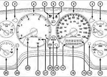
4. Tachometer The tachometer indicates engine speed in revolutions per minute.
CAUTION!
Do not operate the engine with the tachometer pointer at high rpm for extended periods. Engine damage may occur.
5. Airbag Warning Light
The indicator lights and remains lit for six to eight seconds when the ignition is first turned on. If the light stays on, flickers or comes on while driving, have the airbag system checked
by an authorized dealer. 6. High Beam Indicator
This indicator shows that headlights are on high beam.
UNDERSTANDING YOUR INSTRUMENT PANEL 163
7. Seat Belt Reminder Light
When the ignition switch is first turned ON, this light will turn on for five to eight seconds as a bulb check. During the bulb check, if the driver’s seat belt is unbuckled, a chime will sound. After the bulb check or when driving, if the driver seat belt remains unbuckled, the Seat Belt Warning Light will flash or remain on continuously. Refer to ⬙Enhanced Driver Seat Belt Reminder System (BeltAlert威)⬙ under “Occupant Restraints” in section 2. 8. Speedometer The speedometer shows the vehicle speed in miles per hour and/or kilometers per hour.
164 UNDERSTANDING YOUR INSTRUMENT PANEL
9. Oil Pressure Gauge
The pointer should always indicate some oil pres- sure when the engine is running. A continuous high or low reading, under normal driving conditions, may indicate a lubrication system malfunction. Immedi- ate service should be obtained. If the gauge pointer moves to either extreme of NOTE: the gauge, the “Check Gauges” indicator will illuminate and a single chime will sound. 10. Transfer Case Position This display indicator shows the transfer case position selection. For additional information refer to “Four-Wheel Drive Operation” in Section 5 of this manual.
11. TOW HAUL
The TOW HAUL button is located at the end of the shift lever. This light will illuminate when the TOW HAUL OD/OFF button is pushed once.
12. OD/OFF the OD/OFF button is located at the end of the shift lever. This light will illuminate when the TOW HAUL OD/OFF button is pushed twice. 13. Temperature Gauge
The temperature gauge shows engine coolant tem- perature. Any reading within the normal range indicates that the engine cooling system is operat-
ing satisfactorily.
The gauge pointer will likely indicate a higher tempera- ture when driving in hot weather, up mountain grades, or when towing a trailer. It should not be allowed to exceed the upper limits of the normal operating range.
CAUTION!
Driving with a hot engine cooling system could damage your vehicle. If temperature gauge reads “H” pull over and stop the vehicle. Idle the vehicle with the air conditioner turned off until the pointer drops back into the normal range. If the pointer remains on the “H” and you hear continuous chimes, turn the engine off immediately, and call an authorized deal- ership for service.
UNDERSTANDING YOUR INSTRUMENT PANEL 165
WARNING!
A hot engine cooling system is dangerous. You or others could be badly burned by steam or boiling coolant. You may want to call an authorized dealer- ship for service if your vehicle overheats. If you decide to look under the hood yourself, see Section 7
of this manual. Follow the warnings under the Cool- ing System Pressure Cap paragraph.14. Vehicle Security Light — If Equipped
This light will flash at a fast rate for approxi- mately 15 seconds, when the vehicle security alarm is arming, and then will flash slowly until the vehicle is disarmed.
166 UNDERSTANDING YOUR INSTRUMENT PANEL
15. Shift Lever Indicator (Automatic Transmission Only) This display indicator shows the automatic transmission shift lever selection. NOTE: You must apply the brake before shifting from PARK. 16. Odometer/Trip Odometer The odometer shows the total distance the vehicle has been driven. U.S. federal regulations require that upon transfer of vehicle ownership, the seller certify to the purchaser the correct mileage that the vehicle has been driven. Therefore, if the odometer reading is changed during repair or replacement, be sure to keep a record of the reading before and after the service so that the correct mileage can be determined. The two trip odometers show individual trip mileage. To switch from odometer to trip odometers, press and release the Trip Odometer button.
To reset a trip odometer, display the desired trip odom- eter to be reset then push and hold the button until the display resets (approximately two seconds). Vehicle Warning Messages When the appropriate conditions exist, messages such as “door” (indicates that a door(s) may be ajar), “hood” (if the hood is open or ajar, on vehicles with remote start), “gASCAP” (indicates that your gas cap is possibly loose or damaged), “Low Tire” (indicates low tire pressure), ⬙CHANgE OIL” (indicates that the engine oil should be changed), “LoWASH” (low washer fluid), and “noFUSE” (indicates that the IOD fuse is removed from the Inte- grated Power Module), will display in the odometer. NOTE: There is also an engine hour function. This indicates the total number of hours the engine has been running. To display the engine hours perform the follow- ing: Place the ignition in RUN, but do not start the engine. With the odometer value displayed, hold the trip
button down for a period of six seconds. The odometer will change to trip value first, then it will display the engine hour value. The engine hours will be displayed for a period of 30 seconds until the ignition is turned off or the engine is started. Change Oil Message Your vehicle is equipped with an engine oil change indicator system. The “Change Oil” message will flash in the instrument cluster odometer for approximately 12 seconds after a single chime has sounded to indicate the next scheduled oil change interval. The engine oil change indicator system is duty cycle based, which means the engine oil change interval may fluctuate dependent upon your personal driving style. Unless reset, this message will continue to display each time you turn the ignition switch to the ON/RUN position. To turn off the message temporarily, press and release the Trip Odometer button on the instrument
UNDERSTANDING YOUR INSTRUMENT PANEL 167
cluster. To reset the oil change indicator system (after performing the scheduled maintenance) refer to the fol- lowing procedure.
1. Turn the ignition switch to the ON position. (Do not start the engine.) 2. Fully depress the accelerator pedal slowly three times within 10 seconds. 3. Turn the ignition switch to the OFF/LOCK position. If the indicator message illuminates when you NOTE: start the vehicle, the oil change indicator system did not reset. If necessary repeat this procedure. 17. Front Fog Light Indicator — If Equipped
This light shows when the front fog lights are ON.
168 UNDERSTANDING YOUR INSTRUMENT PANEL
18. Malfunction Indicator Light (MIL)
The Malfunction Indicator Light (MIL) is part of an onboard diagnostic system which monitors the emissions and engine control system. If the vehicle is ready for emissions testing the light will come on when the ignition is first turned on and remain on, as a bulb check, until the engine is started. If the vehicle is not ready for emissions testing the light will come on when the ignition is first turned on and remain on for 15 seconds, then blink for five seconds, and remain on until the vehicle is started. If the bulb does not come on during starting, have condition investigated promptly. If this light comes on and remains on while driving, it suggests a potential engine control problem and the need for system service.
the
Although your vehicle will usually be drivable and not need towing, see your authorized dealer for service as soon as possible.
CAUTION!
Prolonged driving with the MIL on could cause damage to the engine control system. It also could affect fuel economy and drivability. If the MIL is flashing, severe catalytic converter damage and power loss will soon occur. Immediate service is required.
19. Brake Warning Light
This light monitors various brake functions, including brake fluid level and parking brake application. If the brake light turns on, it may indicate that the parking brake is applied, that the brake fluid level is low, or that there is a problem with the anti-lock brake system reservoir.
If the light remains on when the parking brake has been disengaged, and the fluid level is at the full mark on the master cylinder reservoir, it indicates a possible brake hydraulic system malfunction or a problem with the Brake Booster has been detected by the Anti-Lock Brake System (ABS) / Electronic Stability Program (ESP) sys- tem. In this case, the light will remain on until the condition has been corrected. If the problem is related to the brake booster, the ABS pump will run when applying the brake and a brake pedal pulsation may be felt during each stop. The dual brake system provides a reserve braking capac- ity in the event of a failure to a portion of the hydraulic system. A leak in either half of the dual brake system is indicated by the Brake Warning Light, which will turn on when the brake fluid level in the master cylinder has dropped below a specified level. The light will remain on until the cause is corrected.
UNDERSTANDING YOUR INSTRUMENT PANEL 169
NOTE: The light may flash momentarily during sharp cornering maneuvers, which change fluid level condi- tions. The vehicle should have service performed, and the brake fluid level checked. If brake failure is indicated, immediate repair is neces- sary.
WARNING!
Driving a vehicle with the red brake light on is dangerous. Part of the brake system may have failed. It will take longer to stop the vehicle. You could have an accident. Have the vehicle checked immediately.
Vehicles equipped with the Anti-Lock Brake System (ABS), are also equipped with Electronic Brake Force Distribution (EBD). In the event of an EBD failure, the Brake Warning Light will turn on along with the ABS Light. Immediate repair to the ABS system is required.
170 UNDERSTANDING YOUR INSTRUMENT PANEL
Operation of the Brake Warning Light can be checked by turning the ignition switch from the OFF position to the ON position. The light should illuminate for approxi- mately two seconds. The light should then turn off unless the parking brake is applied or a brake fault is detected. If the light does not illuminate, have the light inspected by an authorized dealer. The light also will turn on when the parking brake is applied with the ignition switch in the ON position. NOTE: This light shows only that the parking brake is applied. It does not show the degree of brake application. 20. Anti-Lock Brake (ABS) Light
This light monitors the Anti-Lock Brake System (ABS). The light will turn on when the ignition switch is turned to the ON position and may stay on for as long as four seconds.
If the ABS light remains on or turns on while driving, it indicates that the Anti-Lock portion of the brake system is not functioning and that service is required. However, the conventional brake system will continue to operate normally if the BRAKE warning light is not on. If the ABS light is on, the brake system should be serviced as soon as possible to restore the benefits of Anti-Lock brakes. If the ABS light does not turn on when the Ignition switch is turned to the ON position, have the light inspected by an authorized dealer. 21. Electronic Throttle Control (ETC)
This light informs you of a problem with the Electronic Throttle Control (ETC) system. If a problem is detected, the light will come on while the engine is running. If the light remains lit with the engine running your vehicle will usually be drivable, however, see your authorized dealer for service as soon as possible. If the light is flashing when the
engine is running, immediate service is required and you may experience reduced performance, an elevated/ rough idle or engine stall and your vehicle may require towing. The light will come on when the ignition is first turned on and remain on for 15 seconds as a bulb check. If the light does not come on during starting, have the system checked by an authorized dealer. 22. SERV 4WD Indicator
The 4WD indicator will be illuminated when- ever the 4WD mode is engaged for either the manual or electric shift 4WD systems. The SERV 4WD indicator monitors the electric shift 4WD system. If the SERV 4WD light stays on or comes on during driving, it means that the 4WD system is not functioning properly and that service is required.
UNDERSTANDING YOUR INSTRUMENT PANEL 171
23. Transmission Temperature Indicator (Automatic Transmissions Only)
This light indicates that there is excessive trans- mission fluid temperature that might occur with severe usage such as trailer towing. It may also occur when operating the vehicle in a high torque converter slip condition, such as 4-wheel drive operation (e.g., snow plowing, off-road operation). If this light comes on, stop the vehicle and run the engine at idle or faster, with the transmission in NEUTRAL until the light goes off. 24. Odometer/Trip Odometer Button Press this button to toggle between the odometer and the trip odometer display. Holding the button in resets the trip odometer reading when in trip mode. 25. Fuel Gauge Shows level of fuel in tank when ignition switch is in the ON position.
172 UNDERSTANDING YOUR INSTRUMENT PANEL
26. Low Fuel Light
This light illuminates when the pointer is between “E” and 1/8 indication mark (approximately 15% of tank volume) on the fuel gauge. When the fuel gauge pointer is on “E” (equivalent to Distance To Empty [DTE] = 0 on theoverhead console, if so equipped) there is reserve fuel capacity, which corresponds to approxi- mately 8% of tank volume. This reserve capacity was put in place to prevent the likelihood of customers running out of fuel when operating at maximum load conditions in areas where there aren’t many fuel stations. Fuel tank volumes are as follows: • 52 gal (197 L) - Standard Rear Tank • 22 gal (83 L) - Optional Mid Ship Tank 27. CRUISE Indicator
This indicator lights when the electronic speed control system is turned on.
ELECTRONIC DIGITAL CLOCK The clock and radio each use the display panel built into the radio. A digital readout shows the frequency and/or time in hours and minutes (depending on your radio model) whenever the ignition switch is in the ON or ACC position. When the ignition switch is in the OFF position, or when the radio frequency is being displayed, time keeping is accurately maintained. On the RAQ radio the time button alternates the location of the time and frequency on the display. On the REF only one of the two, time or frequency, is displayed at a time. Clock Setting Procedure
1. Press and hold the time button until the hours blink. 2. Adjust the hours by turning the right side Tune/ Audio control.
3. After the hours are adjusted, press the right side Tune/Audio control to set the minutes. 4. Adjust the minutes using the right side Tune/Audio control. 5. To exit, press any button/knob or wait approximately five seconds.
SALES CODE RAQ – AM/FM/CD (6-DISC) RADIO WITH OPTIONAL SATELLITE RADIO, HANDS FREE PHONE, AND VIDEO ENTERTAINMENT SYSTEMS (VES)™ CAPABILITIES
NOTE: The radio sales code is located on the lower right side of your radio faceplate.
UNDERSTANDING YOUR INSTRUMENT PANEL 173
Operating Instructions - Radio Mode
RAQ Radio
NOTE: The ignition switch must be in the ON or ACC position to operate the radio.
174 UNDERSTANDING YOUR INSTRUMENT PANEL
Power Switch/Volume Control (Rotary) Press the ON/VOL control to turn the radio ON. Press the ON/VOL a second time to turn OFF the radio. Electronic Volume Control The electronic volume control turns continuously (360
degrees) in either direction without stopping. Turning the volume control to the right increases the volume and to the left decreases it. When the audio system is turned on, the sound will be set at the same volume level as last played. For your convenience, the volume can be turned down, but not up, when the audio system is off and the ignition is ON. Mode Button (Radio Mode) Press the mode button repeatedly to select between the CD player, Satellite Radio, or Video Entertainment Sys- tem (VES)™ (if equipped).SEEK Button (Radio Mode) Press and release the SEEK button to search for the next listenable station in either AM/FM or Satellite (if equipped) mode. Press the right side of the button to seek up and the left side to seek down. The radio will remain tuned to the new station until you make another selec- tion. Holding the button will bypass stations without stopping until you release it. MUTE Button (Radio Mode) Press the MUTE button to cancel the sound from the speakers. ⬙MUTE⬙ will be displayed. Press the MUTE button a second time and the sound from the speakers will return. Rotating the volume control, turning the radio ON/OFF, or turning OFF the ignition will also return the sound from the speakers NOTE: MUTE button mutes the microphone.
In Hands Free Phone (if equipped) mode, the
SCAN Button (Radio Mode) Pressing the SCAN button causes the tuner to search for the next listenable station, in either AM, FM or Satellite (if equipped) frequencies, pausing for 5 seconds at each listenable station before continuing to the next. To stop the search, press SCAN a second time. MSG or INFO Button (Radio Mode) Press the MSG or INFO button for an RBDS station (one with call letters displayed). The radio will return a Radio Text message broadcast from an FM station (FM mode only). Time Button Press the time button and the time of day will be displayed for 5 seconds. Clock Setting Procedure 1. Press and hold the time button until the hours blink.
UNDERSTANDING YOUR INSTRUMENT PANEL 175
2. Adjust the hours by turning the right side Tune / Audio control. 3. After the hours are adjusted, press the right side Tune / Audio control to set the minutes. The minutes will begin to blink. 4. Adjust the minutes using the right side Tune / Audio control. 5. To exit, press any button/knob or wait 5 seconds. RW/FF (Radio Mode) Pressing the Rewind/Fast Forward button causes the tuner to search for the next frequency in the direction of the arrows. This feature operates in either AM, FM or Satellite (if equipped) frequencies. TUNE Control (Radio Mode) Turn the right side rotary control clockwise to increase or counter-clockwise to decrease the frequency.
176 UNDERSTANDING YOUR INSTRUMENT PANEL
AM/FM Button (Radio Mode) Press the button to select AM or FM Modes. Setting the Tone, Balance, and Fade Press the rotary TUNE control and BASS will display. Turn the TUNE control to the right or left to increase or decrease the Bass tones. Press the rotary TUNE control a second time and MID will display. Turn the TUNE control to the right or left to increase or decrease the Mid Range tones. Press the rotary TUNE control a third time and TREBLE will display. Turn the TUNE control to the right or left to increase or decrease the Treble tones. Press the rotary TUNE control a fourth time and BAL- ANCE will display. Turn the TUNE control to the right or left to adjust the sound level from the right or left side speakers.
Press the rotary TUNE control a fifth time and FADE will display. Turn the TUNE control to the left or right to adjust the sound level between the front and rear speak- ers. Press the rotary TUNE control again to exit setting tone, balance and fade. RND/PTY Button (Program Type Radio Mode) Pressing this button once will turn on the PTY mode for 5 seconds. If no action is taken during the 5 second time out the PTY icon will turn off. Pressing the PTY button or turning the TUNE rotary knob within 5 seconds will allow the program format type to be selected. Many radio stations do not currently broadcast PTY information.
Toggle the PTY button to select the following format types:
Program Type
No program type or un-
defined
Adult Hits Alert Alert Classical
Classic Rock
College Country
Emergency Test Foreign Language
Information
Jazz News
16 Digit-Character
Display
None
Adult_Hits Alert Alert Classical
Classic_Rock
College Country
Emergency Test Foreign_Language
Information
Jazz News
UNDERSTANDING YOUR INSTRUMENT PANEL 177
Program Type
Nostalgia
Oldies
Personality
Public
Rhythm and Blues Religious Music Religious Talk
Rock Soft
Soft Rock
Soft Rhythm and Blues
Sports Talk Top 40
Weather16 Digit-Character
Display Nostalgia
Oldies
Personality
Public
Rhythm_and_Blues
Religious_Music Religious_Talk
Rock Soft
Soft_Rock Soft_R_&_B
Sports Talk
Top_40
Weather178 UNDERSTANDING YOUR INSTRUMENT PANEL
By pressing the SEEK button when the PTY icon is displayed, the radio will be tuned to the next frequency station with the same selected PTY name. The PTY function only operates when in the FM mode. If a preset button is activated while in the PTY (Program Type) mode, the PTY mode will be exited and the radio will tune to the preset station. SET/DIR Button (Radio Mode) — To Set the Push-Button Memory When you are receiving a station that you wish to commit to push-button memory, press the SET/DIR button. The symbol SET 1 will now show in the display window. Select the button (1-6) you wish to lock onto this station and press and release that button. If a button is not selected within 5 seconds after pressing the SET/DIR button, the station will continue to play but will not be stored into push-button memory.
You may add a second station to each push-button by repeating the above procedure with this exception: Press the SET/DIR button twice and SET 2 will show in the display window. Each button can be set for SET 1 and SET 2 in both AM and FM. This allows a total of 12 AM, 12 FM and 12 Satellite (if equipped) stations to be stored into push-button memory. The stations stored in SET 2
memory can be selected by pressing the push-button twice. Every time a preset button is used a corresponding button number will be displayed. Buttons 1 - 6(Radio Mode) These buttons tune the Radio to the stations that you commit to push-button memory {12 AM, 12 FM, and 12
Satellite (if equipped) stations}.position to operate the radio.
Operation Instructions - (CD MODE for CD Audio Play) NOTE: • The ignition switch must be in the ON or ACC • Note: This Radio is capable of playing compact discs (CD), recordable compact discs (CD-R), rewritable compact discs (CD-RW) compact discs with MP3
tracks and multisession compact discs with CD and MP3 tracks.Inserting Compact Disc(s) Gently insert one CD into the CD player with the CD label facing up. The CD will automatically be pulled into the CD Player and the CD icon will illuminate on the radio display.
UNDERSTANDING YOUR INSTRUMENT PANEL 179
CAUTION!
This CD player will accept 4 3/4 inch (12 cm) discs only. The use of other sized discs may damage the CD player mechanism.
You may eject a disc with the radio OFF. If you insert a disc with the ignition ON and the radio ON, the unit will switch from radio to CD mode and begin to play when you insert the disc. The display will show the disc number, the track number, and index time in minutes and seconds. Play will begin at the start of track 1.
180 UNDERSTANDING YOUR INSTRUMENT PANEL
SEEK Button (CD MODE for CD Audio Play) Press the right side of the SEEK button for the next selection on the CD. Press the left side of the button to return to the beginning of the current selection, or return to the beginning of the previous selection if the CD is within the first 10 seconds of the current selection. MUTE Button (CD MODE for CD Audio Play) Press the MUTE button to cancel the sound from the speakers. ⬙MUTE⬙ will be displayed. Press the MUTE button a second time and the sound from the speakers will return. Rotating the volume control, turning the radio ON/OFF, or turning OFF the ignition will also return the sound from the speakers. SCAN Button (CD MODE for CD Audio Play) Press the Scan button to scan through each track on the CD currently playing.
LOAD/EJECT Button (CD Mode for CD Audio Play)
LOAD/ EJECT - Load
Press the LOAD/ EJECT button and the push- button with the corresponding number where the CD is being loaded. The radio will display PLEASE WAIT and prompt when to INSERT DISC. After the radio displays ⬙LOAD DISC⬙ insert the CD into the player. Radio display will show ⬙LOADING DISC⬙ when the disc is loading, and “READING DISC” when the radio is reading the disc. LOAD/ EJECT - Eject
Press the LOAD/ EJECT button and the push- button with the corresponding number where the CD was loaded and the disc will unload and move to the entrance for easy removal.
Radio display will show ⬙EJECTING DISC⬙ when the disc is being ejected and prompt the user to remove the disc. Press and hold the LOAD/ EJECT button for 5 seconds and all CDs will be ejected from the radio. If you have ejected a disc and have not removed it within 15 seconds, it will be reloaded. If the CD is not removed, the radio will continue to play the non-removed CD. If the CD is removed and there are other CD’s in the radio, the radio will play the next CD after a 2 minute timeout. If the CD is removed and there are no other CD’s in the radio, the radio will remain in CD mode and display ⬙INSERT DISC” for 10 seconds. If no discs are inserted within 10 seconds “NO DISCS LOADED” will be dis- played. On some vehicles a disc can be ejected with the radio and ignition OFF.
UNDERSTANDING YOUR INSTRUMENT PANEL 181
TIME Button (CD MODE for CD Audio Play) Press this button to change the display from a large CD playing time display to a small CD playing time display. RW/FF (CD MODE for CD Audio Play) Press and hold FF (Fast Forward) and the CD player will begin to fast forward until FF is released or RW or another CD button is pressed. The RW (Rewind) button works in a similar manner. TUNE Control (CD MODE for CD Audio Play) Pressing the TUNE control allows the setting of the Tone, Fade, and Balance. See Radio Mode. AM/FM Button (CD MODE for CD Audio Play) Switches the Radio into the AM or FM Radio mode.
182 UNDERSTANDING YOUR INSTRUMENT PANEL
RND/PTY Button (Random Play Button) (CD MODE for CD Audio Play) Press this button while the CD is playing to activate Random Play. This feature plays the selections on the compact disc in random order to provide an interesting change of pace. Press the SEEK button to move to the next randomly selected track. Press and hold the FF button to fast forward through the tracks. Release the FF button to stop the fast forward feature. Press the RND button a second time to stop Random Play. Buttons 1 - 6 (CD MODE for CDAudio Play) Selects disc positions 1 - 6 for Play/Load/Eject.
Notes On Playing MP3 Files The radio can play MP3 files, however, acceptable MP3 file recording media and formats are limited. When writing MP3 files, pay attention to the following restrictions. Supported Media (Disc Types) The MP3 file recording media supported by the radio are CD-ROM, CD-R and CD-RW. Supported Medium Formats (File Systems) The medium formats supported by the radio are ISO 9660
Level 1 and Level 2 and includes the Joliet extension. When reading discs recorded using formats other than ISO 9660 Level 1 and Level 2, the radio may fail to read files properly and may be unable to play the file nor- mally. UDF and Apple HFS formats are not supported. The radio uses the following limits for file systems: • Maximum number of directory levels: 15
• Maximum number of files: 255• Maximum number of folders: 100
• Maximum number of characters in file/folder names: • Level 1: 12 (including a separator ⬙.⬙ and a • Level 2: 31 (including a separator3-character extension)
⬙.⬙ and a
3-character extension)
Multisession disc formats are supported by the radio. Multisession discs may contain combinations of normal CD audio tracks and computer files (including MP3 files). Discs created with an option such as ⬙keep disc open after writing⬙ are most likely multisession discs. The use of multisession for CD audio or MP3 playback may result in longer disc loading times. Supported MP3 File Formats The radio will recognize only files with the *.mp3 exten- sion as MP3 files. Non-MP3 files named with the *.mp3
UNDERSTANDING YOUR INSTRUMENT PANEL 183
extension may cause playback problems. The radio is designed to recognize the file as an invalid MP3 and will not play the file. When using the MP3 encoder to compress audio data to an MP3 file, the bit rate and sampling frequencies in the following table are supported. In addition, variable bit rates (VBR) are also supported. The majority of MP3 files use a 44.1 kHz sampling rate and a 192, 160, 128, 96 or VBR bit rates. MPEG
Sampling
Specification
MPEG-1 Audio
Layer 3
MPEG-2 Audio
Layer 3
48, 44.1, 32
Frequency (kHz) Bit rate (kbps) 320, 256, 224, 192, 160, 128, 112, 96, 80, 64, 56, 48, 40, 32
160, 128, 144, 112, 96, 80, 64, 56, 48, 40, 32, 24,24, 22.05, 16
16, 8
184 UNDERSTANDING YOUR INSTRUMENT PANEL
ID3 Tag information for artist, song title and album title are supported for version 1 ID3 tags. ID3 version 2 is not supported by the radios. Playlist files are not supported. MP3 Pro files are not supported. Playback of MP3 Files When a medium containing MP3 data is loaded, the radio checks all files on the medium. If the medium contains a lot of folders or files, the radio will take more time to start playing the MP3 files. Loading times for playback of MP3 files may be affected by the following: • Media - CD-RW media may take longer to load than • Medium formats - Multisession discs may take longer
CD-R media
to load than non-multisession discs
• Number of files and folders - Loading times will
increase with more files and folders
To increase the speed of disc loading, it is recommended to use CD-R media and single-session discs. To create a single-session disc, enable the Disc at Once option before writing to the disc. Operation Instructions - (CD Mode for MP3 Audio Play)
SEEK Button (CD Mode for MP3 Play) Pressing the right side of the SEEK button plays the next MP3 File. Pressing the left side of the SEEK button plays the beginning of the MP3 file. Pressing the button within the first ten seconds plays the previous file.
LOAD/EJECT Button (CD Mode for MP3 Play)
LOAD/ EJECT - Load
Press the LOAD/ EJECT button and the push- button with the corresponding number where the CD is being loaded. The radio will display PLEASE WAIT and prompt when to INSERT DISC. After the radio displays ⬙LOAD DISC⬙ insert the CD into the player. Radio display will show ⬙LOADING DISC⬙ when the disc is loading. LOAD/ EJECT - Eject
Press the LOAD/ EJECT button and the push- button with the corresponding number where the CD was loaded and the disc will unload and move to the entrance for easy removal. Radio display will show ⬙EJECTING DISC⬙ when the disc is being ejected and prompt the user to remove the disc.
UNDERSTANDING YOUR INSTRUMENT PANEL 185
If you have ejected a disc and have not removed it within 15 seconds, it will be reloaded. If the CD is not removed, the radio will continue to play the non-removed CD. If the CD is removed and there are other CD’s in the radio, the radio will play the next CD after a 2 minute timeout. If the CD is removed and there are no other CD’s in the radio, the radio will remain in CD mode and display ⬙INSERT DISC” for 2 minutes. After 2 minutes the radio will go to the previous tuner mode. MSG or INFO Button (CD Mode for MP3 Play) Press and MSG or INFO button while playing MP3 disc. The radio scrolls through the following TAG information: Song Title, Artist, File Name, and Folder Name (if avail- able). Press the MSG or INFO button once more to return to ⬙elapsed time⬙ priority mode.
186 UNDERSTANDING YOUR INSTRUMENT PANEL
Press and hold the MSG or INFO button while in the message display priority mode or elapsed time display priority mode will display the song title for each file. RW/FF (CD Mode for MP3 Play) Press the FF side of the button to move forward through the MP3 selection. TUNE Control (CD Mode for MP3 Play) Pressing the TUNE Control allows the adjustment of Tone, Balance, and Fade. AM/FM Button (CD Mode for MP3 Play) Switches back to Radio mode. RND/ PTY Button (CD Mode for MP3 Play) Pressing this button plays files randomly. SET/DIR Button (CD Mode for MP3 Play) Press the SET/DIR Button to display folders, when playing an MP3 discs that have a file/folder structure.
Turn the TUNE control to display available folders or move through available folders. Press the TUNE control to select a folder. Buttons 1 - 6 (CD Mode for MP3Play) Selects disc positions 1 - 6 for Play/Load/Eject. Operating Instructions - Hands Free Phone (If Equipped) Refer to Hands Free Phone in Section 3 of the Owner’s Manual. Operating Instructions - Satellite Radio Mode (If Equipped) Refer to the Satellite Radio section of Manual. Operating Instructions - Video Entertainment System (VES)™ (If Equipped) Refer to separate Video Entertainment System (VES)™ Guide.
the Owner’s
SALES CODE REF — AM/FM/CD (SINGLE-DISC) RADIO WITH OPTIONAL SATELLITE RADIO AND HANDS-FREE PHONE CAPABILITY
NOTE: The radio sales code is located on the lower right side of your radio faceplate.
REF Radio
UNDERSTANDING YOUR INSTRUMENT PANEL 187
Operating Instructions - Radio Mode
NOTE: The ignition switch must be in the ON or ACC position to operate the radio. Power Switch/Volume Control (Rotary) Press the ON/VOL control to turn the radio ON. Press the ON/VOL a second time to turn OFF the radio. Electronic Volume Control The electronic volume control turns continuously (360– degrees) in either direction without stopping. Turning the volume control to the right increases the volume and to the left decreases it. When the audio system is turned on, the sound will be set at the same volume level as last played. For your convenience, the volume can be turned down, but not up, when the audio system is OFF and the ignition is ON.
188 UNDERSTANDING YOUR INSTRUMENT PANEL
Mode Button (Radio Mode) Press the MODE button repeatedly to select between the CD player and Satellite Radio (if equipped). SEEK Button (Radio Mode) Press and release the SEEK button to search for the next listenable station in either AM/FM or Satellite (if equipped) mode. Press the right side of the button to seek up and the left side to seek down. The radio will remain tuned to the new station until you make another selec- tion. Holding the button will bypass stations without stopping until you release it. MUTE Button (Radio Mode) Press the MUTE button to cancel the sound from the speakers. MUTE will display. Press the MUTE button a second time and the sound from the speakers will return. Rotating the volume control, turning the radio ON/OFF, or turning the ignition ON/OFF, will cancel the MUTE feature.
In Hands-Free Phone (if equipped) mode, the
NOTE: MUTE button mutes the microphone. SCAN Button (Radio Mode) Pressing the SCAN button causes the tuner to search for the next listenable station in either, AM, FM, or Satellite (if equipped) frequencies, pausing for five seconds at each listenable station before continuing to the next. To stop the search, press SCAN a second time. PSCAN Button (Radio Mode) Pressing the PSCAN button causes the tuner to scan through preset stations in either, AM, FM, or Satellite (if equipped) frequencies, pausing for five seconds at each preset station before continuing to the next. To stop the search, press PSCAN a second time. TIME Button Press the TIME button and the time of day will display for five seconds.
Clock Setting Procedure 1. Press and hold the TIME button until the hours blink. 2. Adjust the hours by turning the TUNE/AUDIO con- trol. 3. After the hours are adjusted, press the TUNE/AUDIO control to set the minutes. The minutes will begin to blink. 4. Adjust the minutes using the TUNE/AUDIO control. 5. To exit, press any button/knob or wait five seconds. RW/FF (Radio Mode) Pressing the Rewind/Fast Forward button causes the tuner to search for the next frequency in the direction of the arrows. This feature operates in either AM, FM or Satellite (if equipped) frequencies.
UNDERSTANDING YOUR INSTRUMENT PANEL 189
TUNE Control (Radio Mode) Turn the rotary TUNE control clockwise to increase or counterclockwise to decrease the frequency. AM/FM Button (Radio Mode) Press the button to select AM or FM modes. Setting the Tone, Balance, and Fade Press the rotary TUNE control, and BASS will display. Turn the TUNE control to the right or left to increase or decrease the Bass tones. Press the rotary TUNE control a second time and MID will display. Turn the TUNE control to the right or left to increase or decrease the Mid-Range tones. Press the rotary TUNE control a third time and TREB will display. Turn the TUNE control to the right or left to increase or decrease the Treble tones.
190 UNDERSTANDING YOUR INSTRUMENT PANEL
Press the rotary TUNE control a fourth time and BAL will display. Turn the TUNE control to the right or left to adjust the sound level from the right or left side speakers. Press the rotary TUNE control a fifth time and FADE will display. Turn the TUNE control to the left or right to adjust the sound level between the front and rear speak- ers. Press the tune control again or wait five seconds to exit setting tone, balance, and fade. RND/SET Button (Radio Mode) To Set The Pushbutton Memory When you are receiving a station that you wish to commit to pushbutton memory, press the SET button. The symbol SET 1 will now show in the display window. Select the button (1-6) you wish to lock onto this station and press and release that button. If a button is not
selected within five seconds after pressing the SET but- ton, the station will continue to play but will not be stored into pushbutton memory. You may add a second station to each pushbutton by repeating the above procedure with this exception: Press the SET button twice and SET 2 will show in the display window. Each button can be set for SET 1 and SET 2 in both AM and FM. This allows a total of 12 AM, 12 FM, and 12 Satellite (if equipped) stations to be stored into pushbutton memory. The stations stored in SET 2
memory can be selected by pressing the pushbutton twice. Every time a preset button is used, a corresponding button number will display. Preset Buttons 1 - 6(Radio Mode) These buttons tune the Radio to the stations that you commit to pushbutton memory, 12 AM, 12 FM, and 12
Satellite (if equipped) stations.Operating Instructions - CD Mode
NOTE: The ignition switch must be in the ON or ACC position to operate the radio. Inserting The Compact Disc (Single CD Player) Gently insert one CD into the CD player with the CD label facing up. The CD will automatically be pulled into the CD Player and the CD icon will illuminate on the radio display. If the volume control is ON, the unit will switch to CD mode and begin to play. The display will show the track number and play time in minutes and seconds. Play will begin at the start of track one. NOTE: • On some vehicles, you may insert or eject a disc with
the radio or ignition switch OFF.
UNDERSTANDING YOUR INSTRUMENT PANEL 191
• If you insert a disc with the ignition ON and the radio OFF, the CD will automatically be pulled into the CD player.
• This radio does not play discs with MP3 tracks. SEEK Button (CD Mode) Press the right side of the SEEK button for the next track on the CD. Press the left side of the button to return to the beginning of the current track, or return to the beginning of the previous track if the CD is within the first 10 seconds of the current selection. MUTE Button (CD Mode) Press the MUTE button to cancel the sound from the speakers. ⬙MUTE⬙ will display. Press the MUTE button a second time and the sound from the speakers will return. Rotating the volume control or turning the ignition OFF/ON will also return the sound from the speakers.
192 UNDERSTANDING YOUR INSTRUMENT PANEL
SCAN Button (CD Mode) Press this button to play the first 10 seconds of each track. To stop the scan function, press the button a second time. EJECT Button (CD Mode)
Press this button and the disc will unload and move to the entrance for easy removal. The unit will switch to the last selected mode.
If you do not remove the disc within 15 seconds, it will be reloaded. The radio mode will continue to appear. TIME Button (CD Mode) Press this button to change the display from elapsed CD playing time to time of day. The time of day will display for five seconds. RW/FF (CD Mode) Press and hold the FF (Fast Forward) and the CD player will begin to fast forward until FF is released. The RW (Rewind) button works in a similar manner.
Press and hold the FF button to fast forward through the tracks. Release the FF button to stop the fast forward feature. If the RW button is pressed, the current track will reverse to the beginning of the track and begin playing. RND/SET Button (Random Play Button) (CD Mode) Press this button while the CD is playing to activate Random play. This feature plays the selections on the compact disc in random order to provide an interesting change of pace. Press the SEEK button to move to the next randomly selected track. Press the RND button a second time to stop Random play. Operating Instructions - Auxiliary Mode The auxiliary (AUX) jack is an audio input jack, which allows the user to plug in a portable device such as an
MP3 player, cassette player, or microphone and utilize the vehicle’s audio system to amplify the source and play through the vehicle speakers. The auxiliary mode becomes active when an electrical device is plugged into the AUX jack using a standard 3.5 mm stereo audio cable and the user presses and releases the MODE button until AUX appears on the display. NOTE: The radio will return to the last stored mode if the ignition switch is turned from the OFF/LOCK posi- tion to the ACC position, the radio is turned on, and the radio was previously in the AUX mode. SEEK Button (Auxiliary Mode) No function. MUTE Button (Auxiliary Mode) Press the MUTE button to cancel the sound from the speakers. ⬙MUTE⬙ will display. Press the MUTE button a
UNDERSTANDING YOUR INSTRUMENT PANEL 193
second time and the sound from the speakers will return. Rotating the volume control or turning the ignition OFF/ON will also return the sound from the speakers. SCAN Button (Auxiliary Mode) No function. EJECT Button (Auxiliary Mode)
No function.
PSCAN Button (Auxiliary Mode) No function. TIME Button (Auxiliary Mode) Press this button to change the display from elapsed playing time to time of day. The time of day will display for five seconds.
194 UNDERSTANDING YOUR INSTRUMENT PANEL
RW/FF (Auxiliary Mode) No function. RND/SET Button (Auxiliary Mode) No function. Mode Button (Auxiliary Mode) Press the MODE button repeatedly to select between the CD player and Satellite Radio (if equipped). Operating Instructions - Hands-Free Phone — If Equipped Refer to the “Hands-Free Phone (UConnect威)” section of this Owner’s Manual. Operating Instructions - Satellite Radio — If Equipped Refer to the “Satellite Radio” section of this Owner’s Manual.
SALES CODE REC — AM/FM/CD (6–DISC) RADIO WITH NAVIGATION SYSTEM
Satellite Navigation Radio and CD Player with MP3
Capability (REC) combines a Global-Positioning System-based navigation system with an integrated color screen to provide maps, turn identification, selectionUNDERSTANDING YOUR INSTRUMENT PANEL 195
the worldwide standard for time. This makes the sys- tem’s clock very accurate once the appropriate time zone and daylight savings information is set. 1. At the Main Menu screen, highlight “Clock Setup” and press ENTER OR press and hold the TIME button on the unit’s faceplate for three seconds. The Clock Setup screen appears.
menus and instructions for selecting a variety of destina- tions and routes, AM/FM stereo radio and six-disc CD changer with MP3 capability. Mapping information for navigation is supplied on a DVD that is loaded into the unit. One map DVD covers all of North America. Refer to your “Navigation User’s Manual” for detailed operating instructions. Operating Instructions — Satellite Radio — If Equipped Refer to your “Navigation User’s Manual” for detailed operating instructions. REC Setting the Clock
GPS Clock The GPS receiver used in this system is synchronized to the time data being transmitted by the GPS satellites. The satellites’ clock is Greenwich Mean Time (GMT). This is
196 UNDERSTANDING YOUR INSTRUMENT PANEL
2. To show the GPS clock, select “Displayed Clock: GPS Clock” and press ENTER. 3. To adjust the time zone, Select “Time Zone” and press ENTER. Select the appropriate time zone and press ENTER. 4. To turn daylight savings on or off, select “Daylight Savings” and press ENTER. Select “On” or “Off” and press ENTER. 5. Select DONE to exit from the clock setting mode. Press ENTER to save your changes. If you press CANCEL or NAV then your changes will not be saved. User Defined Clock If you wish to set the clock to a time different than the system clock, you can manually adjust the time by choosing the “User Defined Clock” option. 1. At Clock: User Defined Clock”.
the Clock Setup screen highlight “Displayed
2. To increase the clock by hours, make sure “HR +” is highlighted and press ENTER. Press ENTER again to increase the clock by another hour. You will see on the “User Defined Time” display the number of hours you have increased the clock by.
3. To decrease the clock by one hour, use the Select Encoder to highlight the “-” sign. Press ENTER. Press ENTER again to decrease the clock by another hour. 4. To increase the clock by minutes, make sure “MIN +” is highlighted and press ENTER. Press ENTER again to increase the clock by another minute. 5. To decrease the clock by minutes, use the Select Encoder to highlight the “-“ sign. Press ENTER. Press ENTER again to decrease the clock by another minute. 6. Select “DONE” to exit from the clock setting mode. Press ENTER to save your changes. If you press CAN- CEL or NAV then your changes will not be saved.
SATELLITE RADIO — IF EQUIPPED Satellite radio uses direct satellite to receiver broadcast- ing technology to provide clear digital sound, coast to coast. The subscription service provider is Sirius Satellite
UNDERSTANDING YOUR INSTRUMENT PANEL 197
Radio. This service offers over 130 channels of music, sports, news, entertainment, and programming for chil- dren, directly from its satellites and broadcasting studios. NOTE: Sirius service is not available in Hawaii and has limited coverage in Alaska. System Activation Sirius Satellite Radio service is pre-activated, and you may begin listening immediately to the one year of audio service that is included with the factory-installed satellite radio system in your vehicle. Sirius will supply a wel- come kit that contains general information, including how to setup your on-line listening account at no addi- tional charge. For further information, call the toll-free
198 UNDERSTANDING YOUR INSTRUMENT PANEL
number 888-539-7474, or visit the Sirius web site at www.sirius.com, or at www.siriuscanada.ca for Cana- dian residents. Electronic Serial Number/Sirius Identification Number (ESN/SID) Please have the following information available when calling: 1. The Electronic Serial Number/Sirius Identification Number (ESN/SID). 2. Your Vehicle Identification Number. To access the ESN/SID, refer to the following procedure. ESN/SID Access with REF Radios With the ignition switch in the ACC position and the radio OFF, press the CD Eject and TIME buttons simul- taneously for three seconds. The first four digits of the 12-digit ESN/SID number will display. Press the SEEK UP button to display the next four digits. Continue to
press the SEEK UP button until all 12 ESN/SID digits display. The SEEK DOWN will page down until the first four digits display. The radio will exit the ESN/SID mode when any other button is pushed, the ignition is turned OFF, or five minutes have passed since any button was pushed. ESN/SID Access with RAQ and RAK Radios With the ignition switch in the ACC position and the radio OFF, press the CD Eject and TIME buttons simul- taneously for three seconds. All twelve ESN/SID num- bers will display. The radio will exit the ESN/SID mode when any other button is pushed, the ignition is turned OFF, or five minutes have passed since any button was pushed. ESN/SID Access with REC Navigation Radios Please refer to your Navigation User’s Manual.
With the ignition in the ACC position and the radio off, press the CD Eject and SET buttons simultaneously until the 12 digits of the ESN/SID appear on the screen. Selecting Satellite Mode in REF, RAQ, And RAK Radios
Selecting Satellite Mode — REF Radio Press the MODE button repeatedly until the word ⬙SAT⬙ appears in the display. A CD may remain in the radio while in the Satellite radio mode. Selecting Satellite Mode — RAQ and RAK Radio Press the MODE button repeatedly until the word ⬙SAT⬙ appears in the display. These radios will also display the current station name and program type. For more information, such as song title and artist, press the MSG or INFO button.
UNDERSTANDING YOUR INSTRUMENT PANEL 199
A CD or tape may remain in the radio while in the Satellite radio mode. Selecting A Channel Press and release the SEEK or TUNE knob to search for the next channel. Press the top of the button to search up and the bottom of the button to search down. Holding the TUNE button causes the radio to bypass channels until the button is released. Press and release the SCAN button (if equipped) to automatically change channels every seven seconds. The radio will pause on each channel for seven seconds before moving on to the next channel. The word ⬙SCAN⬙ will appear in the display between each channel change. Press the SCAN button a second time to stop the search. NOTE: Channels that may contain objectionable content can be blocked. Contact Sirius Customer Care at 888-539- 7474 to discuss options for channel blocking or unblock- ing. Please have your ESN/SID information available.
200 UNDERSTANDING YOUR INSTRUMENT PANEL
Storing And Selecting Preset Channels In addition to the 12 AM and 12 FM preset stations, you may also commit 12 satellite stations to pushbutton memory. These satellite channel preset stations will not erase any AM or FM preset memory stations. Follow the memory preset procedures that apply to your radio. Using The PTY (Program Type) Button — If Equipped Follow the PTY button instructions that apply to your radio. PTY Button SCAN When the desired program type is obtained, press the SCAN button within five seconds. The radio will play seven seconds of the selected channel before moving to the next channel of the selected program type. Press the SCAN button a second time to stop the search. NOTE: Pressing the SEEK or SCAN button, while performing a music type scan, will change the channel by
one and stop the search. Pressing a preset memory button during a music type scan will call up the memory channel and stop the search. PTY Button SEEK When the desired program is obtained, press the SEEK button within five seconds. The channel will change to the next channel that matches the program type selected. Satellite Antenna To ensure optimum reception on vehicles available with a luggage rack, do not place items on the roof around the rooftop antenna location. Metal objects placed within the line of sight of the antenna will cause decreased perfor- mance. Larger luggage items should be placed as far forward as possible. Do not place items directly on or above the antenna.
structure or under a physical obstacle.
Reception Quality Satellite reception may be interrupted due to one of the following reasons: • The vehicle is parked in an underground parking • Dense tree coverage may interrupt reception. • Driving under wide bridges or along tall buildings can • Placing objects over or too close to the antenna can
cause intermittent reception.
cause signal blockage.
UNDERSTANDING YOUR INSTRUMENT PANEL 201
front row seat. Refer to your VES™ User’s Manual for detailed operating instructions.
REMOTE SOUND SYSTEM CONTROLS — IF EQUIPPED The remote sound system controls are located on the rear surface of the steering wheel. Reach behind the wheel to access the switches.
VIDEO ENTERTAINMENT SYSTEM™ (SALES CODE XRV) — IF EQUIPPED The optional Video Entertainment System (VES)™ con- sists of a DVD player and LCD (liquid crystal display) screen, a battery-powered remote control, and two head- sets. The system is located in the headliner behind the
Remote Sound System Controls
202 UNDERSTANDING YOUR INSTRUMENT PANEL
The right-hand control is a rocker type switch with a button in the center. Pressing the top of the switch will increase the volume and pressing the bottom of the switch will decrease the volume. The center button of the right-hand control will allow you to change the mode. The left-hand control is a rocker type switch with a push button in the center. The function of the left-hand control is different, depending on which mode you are in. The following describes the left-hand control operation in each mode. Radio Operation Pressing the top of the left side switch will seek up for the next listenable station and pressing the bottom of the switch will seek down for the next listenable station. The button located in the center of the left-hand control will tune to the next pre-set station that you have programmed in the radio pre-set push-buttons.
Tape Player Pressing the top of the switch once will go to the next selection on the cassette. Pressing the bottom of the switch once will go to the beginning of the current selection or to the beginning of the previous selection if it is within the first five seconds of the current selection. If you press the switch up or down twice it plays the second selection; three times, it will play the third, etc. The button in the center of the left-hand switch has no function in this mode. CD Player Pressing the top of the switch once will go to the next track on the CD. Pressing the bottom of the switch once will go to the beginning of the current track or to the beginning of the previous track if it is within one second after the current track; begins to play.
If you press the switch up or down twice it plays the second track, three times, it will play the third, etc. The button in the center of the left-hand switch has no function in this mode.
CD/DVD MAINTENANCE To keep a CD/DVD in good condition, take the following precautions: 1. Handle the disc by its edge; avoid touching the surface. 2. If the disc is stained, clean the surface with a soft cloth, wiping from center to edge. 3. Do not apply paper or tape to the disc; avoid scratch- ing the disc. 4. Do not use solvents such as benzene, thinner, cleaners, or antistatic sprays.
UNDERSTANDING YOUR INSTRUMENT PANEL 203
5. Store the disc in its case after playing. 6. Do not expose the disc to direct sunlight. 7. Do not store the disc where temperatures may become too high. If you experience difficulty in playing a particu- NOTE: lar disc, it may be damaged (i.e. scratched, reflective coating removed, a hair, moisture or dew on the disc) oversized, or have theft protection encoding. Try a known good disc before considering disc player service.
RADIO OPERATION AND CELLULAR PHONES Under certain conditions, the operation of a cellular phone in your vehicle can cause erratic or noisy perfor- mance from your radio. This condition may be lessened or eliminated by relocating the cellular phone antenna. This condition is not harmful to the radio. If your radio performance does not satisfactorily “clear” by the repo- sitioning of the antenna, it is recommended that the radio volume be turned down or off during cellular phone operation.
204 UNDERSTANDING YOUR INSTRUMENT PANEL
CLIMATE CONTROLS The controls for the heating and ventilation system in this vehicle consist of a series of rotary knobs. These comfort controls can be set to obtain desired interior conditions.
Heater Only — If Equipped
Climate Control Location
Manual Heating Controls
The mode control (at the right of the control panel) can be set in any of the following positions:
NOTE: To improve your selection choices, the system allows you to operate at intermediate positions between the major modes. These intermediate positions are iden- tified by the small dots. Panel
Outside air flows through the outlets located in the instrument panel.
Recirculation Modes (Panel or Bi-Level)
Select the recirculation modes when the outside air contains smoke or odors. This feature allows for recircu- lation of interior air only. Air flows through the panel outlets in this mode. Air flows through the panel only or through both the panel and floor vents
depending on the selected mode (panel vs bi-level).
UNDERSTANDING YOUR INSTRUMENT PANEL 205
Bi-Level
Outside air flows through the outlets located in the instrument panel and at the floor.
Mix
Outside air flows in equal proportions through the floor and defroster outlets.
Defrost
Outside air is primarily directed to the windshield through the defroster outlets located at the base of the windshield, and the demister outlets located at the edge of each side of the instrument panel.
206 UNDERSTANDING YOUR INSTRUMENT PANEL
Blower Control
The rotary knob on the left of the control panel is the blower control. Turn the knob clockwise to one of the four positions to obtain the blower speed you desire. To turn the blower off, turn the knob to the far left posi- tion.
NOTE: For vehicles equipped with Remote Start, the climate controls will not function during Remote Start operation if the blower control is left in the “O” (Off) position.
Temperature Control
The rotary knob at the center of the control panel controls the temperature of the interior air. You can choose your degree of comfort by rotating the knob. The coldest temperature setting is to the extreme left (blue region) and the warmest setting is to the extreme
right (red region) of the rotation.
UNDERSTANDING YOUR INSTRUMENT PANEL 207
outlets selected by the mode control. A light in the snowflake button shows that the air conditioning is on. Press the button a second time to turn the air condition- ing off. Slight changes in engine speed or power may be noticed when the air conditioning compressor is on. This is a normal occurrence, as the compressor will cycle on and off to maintain comfort and increase fuel economy.
The mode control (at the right of the control panel) can be set in any of the following positions:
Air Conditioning and Heating — If Equipped
Air Conditioning And Heating
Air Conditioning Operation
To turn on the air conditioning, set the fan control at any speed and press the snowflake button located at the right of the control panel. Conditioned air will be directed through the
208 UNDERSTANDING YOUR INSTRUMENT PANEL
NOTE: To improve your selection choices, the system allows you to operate at intermediate positions between the major modes. These intermediate positions are iden- tified by the small dots. Recirculation Modes (Panel or Bi-Level)
Select the recirculation modes when the outside air contains smoke, odors, high humidity, or if rapid cooling is desired. This feature allows for recir- culation of interior air only. Air flows through the panel only or through both the panel and floor vents depend-
ing on the selected mode (panel vs bi-level). NOTE: Selecting a “Recirculation Mode” mode does not necessarily consume more fuel than normal A/C mode. Panel
Outside air flows through the outlets located in the instrument panel.
Bi-Level
Outside air flows through the outlets located in the instrument panel and at the floor.
Floor
Mix
Outside air flows primarily through the floor out- lets located under the instrument panel.
Outside air flows in equal proportions through the floor and defroster outlets, and the air conditioning may be on.
Defrost
Outside air is primarily directed to the windshield through the defroster outlets located at the base of the windshield, and the demister outlets located at the edge of each side of the instrument panel, and the air conditioning may be on.
Blower Control
The rotary knob on the left of the control panel is the blower control. Turn the knob clockwise to one of the four positions to obtain the blower speed you desire. To turn the blower off, turn the knob to the far left position.
Temperature Control
The rotary knob at the center of the control panel controls the temperature of the interior air. You can choose your degree of comfort by rotating the knob. The coldest temperature setting is to the extreme left (blue region) and the warmest setting is to the extreme
right (red region) of the rotation.
UNDERSTANDING YOUR INSTRUMENT PANEL 209
Circulation The cab is designed with features to promote outside air circulation. There are grilles in the cab back panel. These are air exhausters that provide the means for regular exchange of cab air. Side window demisters direct air flow specifically to the window glass to help prevent interior fogging of the glass. They are located in the extreme outside upper edges of the instrument panel. The demisters also pro- vide extra air ducts for circulation. They are in operation whenever the Floor, Mix or Defrost modes are in use. To remove frost from the side windows, it is best to use the full defrost mode. NOTE: When you turn off the engine you may hear a hissing sound from under the hood for a short period of time. This is a normal condition that occurs if the air conditioning system has been on. It is not an indication of a problem with the air conditioning system.
210 UNDERSTANDING YOUR INSTRUMENT PANEL
Air Conditioning With Dual Zone Temperature Control — If Equipped With the Dual Zone Temperature Control System, each front seat occupant can independently control the tem- perature of air coming from the outlets on their side of the vehicle.
Dual Zone Control Head
Air Conditioning and Heating Operation To turn on the air conditioning, set the fan control at any speed and press the snowflake button located on the control panel. Conditioned air will be directed through the outlets selected by the mode control. A light in the snowflake button shows that the air conditioning is on. Press the button a second time to turn the air condition- ing off. A/C Push-button
With the fan control in the ON posi- tion, pushing the A/C button turns on the air conditioning compressor. An indicator light on the button shows that the air conditioning compressor is on. Conditioned air is now directed through the mode outlets selected. Pushing the button a second time turns the compressor OFF.
Recirculation Pushbutton
Pushing the Recirculation button al- lows interior air to recirculate continu- ously in any position except defrost and defrost/floor mode for rapid cool down of the interior. Refer to “Fast Cooldown” in this section.
Mode Control
The mode control allows you to choose from several patterns of air distribution.
NOTE: To improve your selection choices, the system allows you to operate at intermediate positions between
UNDERSTANDING YOUR INSTRUMENT PANEL 211
the major modes. These intermediate positions are iden- tified by the small dots and give an even blend of both modes. Panel
Outside air flows through the outlets located in the instrument panel. These outlets can be adjusted to
direct the airflow. Bi-Level
Air flows through the outlets located in the instru- ment panel and those located on the floor.
NOTE: There is a difference in temperature between the upper and lower outlets for added comfort. The warmer air goes to the floor outlets. This feature gives improved comfort during sunny but cool conditions. Heat
Outside air flows primarily through the floor out- lets located under the instrument panel.
212 UNDERSTANDING YOUR INSTRUMENT PANEL
Mix
Outside air flows in equal proportions through the floor and defroster outlets.
Blower Control
Defrost
Outside air is primarily directed to the windshield through the defroster outlets located at the base of
the windshield and side window demist outlets. NOTE: The air conditioning compressor operates in both Mix and Defrost or a blend of these modes, even if the A/C button has not been pressed. This dehumidifies the air to help dry the windshield.
The rotary knob on the left of the control panel is the blower control. Turn the knob clockwise to one of the four positions to obtain the blower speed you desire. To turn the blower off, turn the knob to the far left position.
Dual Zone Temperature Control
Dual Zone Temperature Control
Use this control to regulate the temperature of the air inside the passenger compartment. This is accomplished by having separate temperature control slides for both the driver and front passenger. The blue area of the scale indicates cooler temperatures, while the red area indi- cates warmer temperatures.
UNDERSTANDING YOUR INSTRUMENT PANEL 213
Circulation The cab is designed with features to promote outside air circulation. There are grilles in the cab back panel. These are air exhausters that provide the means for regular exchange of cab air. Side window demisters direct air flow specifically to the window glass to help prevent interior fogging of the glass. They are located in the extreme outside upper edges of the instrument panel. The demisters also pro- vide extra air ducts for circulation. They are in operation whenever the Floor, Mix or Defrost modes are in use. NOTE: When you turn off the engine you may hear a hissing sound from under the hood for a short period of time. This is a normal condition that occurs if the air conditioning system has been on. It is not an indication of a problem with the air conditioning system.
214 UNDERSTANDING YOUR INSTRUMENT PANEL
Operating Tips
Fast Cooldown For a fast cooldown, turn the blower fan rotary knob to the extreme right position, turn the mode control to the panel fresh position, press the snowflake button to turn on the air conditioning, and drive with the windows open for the first few minutes. Once the hot air has been expelled, close the windows and press the recirculation pushbutton on dual zone control, or switch the mode from panel/fresh to panel/recirculate on single zone control. When a comfortable condition has been reached, choose a mode position and adjust the temperature control slide and blower speed as necessary to maintain comfort. For high humidity conditions it may be neces- sary to remain in the Recirculation mode to maintain comfort.
Window Fogging Windows will fog on the inside when the humidity inside the vehicle is high. This often occurs in mild or cool temperatures when it’s rainy or humid. In most cases turning on the air conditioning (pressing the snowflake button) will clear the fog. Adjust the temperature control, air direction and blower speed to maintain comfort. As the temperature gets colder it may be necessary to direct air onto the windshield by using the Mix mode position on the control. Adjust the temperature control and blower speed to maintain comfort. Higher blower speeds will reduce fogging. Interior fogging on the windshield can be quickly removed by selecting the defrost mode. Regular cleaning of the inside of the windows with a non-filming cleaning solution (vinegar and water works very well) will help prevent contaminates (cigarette
UNDERSTANDING YOUR INSTRUMENT PANEL 215
Your air conditioning system is also equipped with an automatic recirculation system. When the system senses a heavy load or high heat conditions, it may use partial Recirculation A/C mode to provide additional comfort. Winter Operation When operating the system during the winter months, make sure the air intake, located directly in front of the windshield, snow, or other obstructions.
free of
slush,
ice,
is
smoke, perfumes, etc.) from sticking to the windows. Contaminates increase the rate of window fogging. Summer Operation Air conditioned vehicles must be protected with a high quality antifreeze coolant during summer to provide proper corrosion protection and to raise the boiling point of the coolant for protection against overheating. A 50 % concentration is recommended. Refer to ”Engine Cool- ant” under “ Fluids, Lubricants and Genuine Parts” in section 7. When using the air conditioner in extremely heavy traffic in hot weather, especially when towing a trailer, addi- tional engine cooling may be required. If this situation is encountered, operate the transmission in a lower gear to increase engine RPM, coolant flow and fan speed. When stopped in heavy traffic, it may be necessary to shift into NEUTRAL and depress the accelerator slightly for fast idle operation to increase coolant flow and fan speed.
216 UNDERSTANDING YOUR INSTRUMENT PANEL
Operating Tips Chart
STARTING AND OPERATING
CONTENTS
䡵 Starting Procedures . . . . . . . . . . . . . . . . . . . . 221
▫ Normal Starting . . . . . . . . . . . . . . . . . . . . . 221
▫ Automatic Transmission . . . . . . . . . . . . . . . 221
▫ If Engine Fails To Start . . . . . . . . . . . . . . . . 222
▫ After Starting . . . . . . . . . . . . . . . . . . . . . . . 223
䡵 Engine Block Heater — If Equipped . . . . . . . . 223
䡵 Automatic Transmission . . . . . . . . . . . . . . . . . 224
▫ Automatic Transmission With Overdrive . . . . 224䡵 Four-Wheel Drive Operation — If Equipped . . 230
▫ Manually Shifted Transfer Case Operating
Information/Precautions . . . . . . . . . . . . . . . 230
▫ Shifting Procedure - Manually Shifted
Transfer Case . . . . . . . . . . . . . . . . . . . . . . . 233
. . . . . . . . . . . 234▫ Transfer Case Reminder Light ▫ Electronically Shifted Transfer Case
Operating Information/Precautions (5
Position Switch) — If Equipped . . . . . . . . . . 234▫ Shifting Procedure — Electronically Shifted
Transfer Case . . . . . . . . . . . . . . . . . . . . . . . 239
218 STARTING AND OPERATING
▫ Electronically Shifted Transfer Case
Operating Information/Precautions (4
Position Switch) — If Equipped . . . . . . . . . . 242▫ Shifting Procedure — Electronically Shifted
Transfer Case . . . . . . . . . . . . . . . . . . . . . . . 246
䡵 Limited-Slip Differential – If Equipped . . . . . . 249
䡵 Driving On Slippery Surfaces . . . . . . . . . . . . . 250
䡵 Driving Through Water . . . . . . . . . . . . . . . . . 250
▫ Flowing/Rising Water . . . . . . . . . . . . . . . . . 250
▫ Shallow Standing Water . . . . . . . . . . . . . . . 251
䡵 Power Steering . . . . . . . . . . . . . . . . . . . . . . . 252
▫ Power Steering Fluid Check . . . . . . . . . . . . . 253
䡵 Parking Brake . . . . . . . . . . . . . . . . . . . . . . . . 254
䡵 Brake System . . . . . . . . . . . . . . . . . . . . . . . . 255▫ Four-Wheel Anti-Lock Brake System . . . . . . . 256
䡵 Tire Safety Information . . . . . . . . . . . . . . . . . 258
▫ Tire Markings . . . . . . . . . . . . . . . . . . . . . . . 258
▫ Tire Identification Number (TIN) . . . . . . . . . 261
▫ Tire Loading And Tire Pressure . . . . . . . . . . 262
䡵 Tires — General Information . . . . . . . . . . . . . 266
▫ Tire Pressure . . . . . . . . . . . . . . . . . . . . . . . 266
▫ Tire Inflation Pressures . . . . . . . . . . . . . . . . 267
▫ Radial Ply Tires . . . . . . . . . . . . . . . . . . . . . 272
▫ Tire Spinning . . . . . . . . . . . . . . . . . . . . . . . 273
▫ Tread Wear Indicators . . . . . . . . . . . . . . . . . 273
▫ Life Of Tire . . . . . . . . . . . . . . . . . . . . . . . . 274
▫ Replacement Tires . . . . . . . . . . . . . . . . . . . . 274䡵 Supplemental Tire Pressure Information —
If Equipped . . . . . . . . . . . . . . . . . . . . . . . . . . 276
䡵 Tire Chains . . . . . . . . . . . . . . . . . . . . . . . . . . 276
䡵 Snow Tires . . . . . . . . . . . . . . . . . . . . . . . . . . 278
䡵 Tire Rotation Recommendations . . . . . . . . . . . 279
▫ Dual Rear Wheels . . . . . . . . . . . . . . . . . . . . 280
䡵 Fuel Requirements . . . . . . . . . . . . . . . . . . . . . 281
▫ 5.7L Gas Engine . . . . . . . . . . . . . . . . . . . . . 281
. . . . . . . . . . . . . . . . . . . . . . . . . 285
▫ Loose Fuel Filler Cap (Gas Cap) Message . . . 286
. . . . . . . . . . . . . . . . . . . . . . 287
. . . . . . . . . . . . . . . . . . . 287
䡵 Trailer Towing . . . . . . . . . . . . . . . . . . . . . . . . 289▫ Certification Label
䡵 Vehicle Loading
䡵 Adding Fuel
STARTING AND OPERATING 219
▫ Common Towing Definitions . . . . . . . . . . . . 289
▫ Trailer Hitch Classification . . . . . . . . . . . . . . 292
▫ Trailer Towing Weights (Maximum TrailerWeight Ratings)
. . . . . . . . . . . . . . . . . . . . . 293
▫ Trailer And Tongue Weight . . . . . . . . . . . . . 294
▫ Towing Requirements . . . . . . . . . . . . . . . . . 295
▫ Towing Tips . . . . . . . . . . . . . . . . . . . . . . . . 299
䡵 Snowplow . . . . . . . . . . . . . . . . . . . . . . . . . . 300
▫ Before Plowing . . . . . . . . . . . . . . . . . . . . . . 301
▫ Snowplow Prep Package Model Availability . 302
▫ Over The Road Operation With SnowplowAttached . . . . . . . . . . . . . . . . . . . . . . . . . . 303
▫ Operating Tips . . . . . . . . . . . . . . . . . . . . . . 303
▫ General Maintenance . . . . . . . . . . . . . . . . . . 303220 STARTING AND OPERATING
䡵 Recreational Towing (Behind Motorhome, Etc.) . 304
▫ Recreational Towing –
2-Wheel Drive Models . . . . . . . . . . . . . . . . . 304
▫ Recreational Towing –
4-Wheel Drive Models . . . . . . . . . . . . . . . . . 305
STARTING PROCEDURES Before starting your vehicle, adjust your seat, adjust both inside and outside mirrors, and fasten your seat belts. The starter should not be operated for more than 15- second intervals. Waiting a few seconds between such intervals will protect the starter from overheating.
WARNING!
• Be sure to turn off the engine and remove the key from the ignition switch if you want to rest or sleep in your vehicle. Accidents can be caused by inadvertently moving the shift lever or by press- ing the accelerator pedal. This may cause excessive heat in the exhaust system, resulting in overheat- ing and vehicle fire which may cause serious or fatal injuries.
(Continued)
STARTING AND OPERATING 221
WARNING! (Continued)
• Do not leave children or animals inside parked vehicles in hot weather. Interior heat buildup may cause serious injury or death.
Normal Starting Normal starting of either a warm or cold engine is obtained without pumping or depressing the accelerator pedal. Turn the key to the START position and release when the engine starts. If the engine fails to start within 10 seconds, turn the key to the OFF position, wait five seconds, then repeat the starting procedure. Automatic Transmission Start the engine with the shift lever in the NEUTRAL or PARK position. Apply the brake before shifting to any driving range.
222 STARTING AND OPERATING
NOTE: This vehicle is equipped with a transmission shift interlocking system. The brake pedal must be depressed to shift out of PARK.
Tip Start Feature Do not press the accelerator. Turn the ignition key briefly to START position, and release it. The starter motor will continue to run, but will automatically disengage when the engine is running. If Engine Fails To Start If the engine fails to start after you have followed the “Normal Starting” procedure, it may be flooded. Push the accelerator pedal all the way to the floor and hold it there while cranking the engine. This should clear any excess fuel in case the engine is flooded.
CAUTION!
To prevent damage to the starter, do not crank the engine for more than 15 seconds at a time. Wait 10 to 15 seconds before trying again.
WARNING!
• Never pour fuel or other flammable liquids into the throttle body air inlet opening in an attempt to start the vehicle. This could result in a flash fire causing serious personal injury. • Do not attempt to push or tow your vehicle to get it started. Vehicles equipped with an automatic transmission cannot be started this way. Unburned fuel could enter the catalytic converter and once the engine has started, ignite and damage the converter and vehicle.
(Continued)
WARNING! (Continued)
• If the vehicle has a discharged battery, booster cables may be used to obtain a start from a booster battery or the battery in another vehicle. This type of start can be dangerous if done improperly. Refer to “Jump Starting” in Section 6.
If the engine has been flooded, it may start to run, but not have enough power to continue running when the key is released. If this occurs, continue cranking with the accel- erator pedal pushed all the way to the floor. Release the accelerator pedal and the key once the engine is running smoothly. If the engine shows no sign of starting after two 15- second periods of cranking with the accelerator pedal held to the floor, the “Normal Starting” procedure should be repeated.
STARTING AND OPERATING 223
After Starting The idle speed is automatically controlled and will de- crease as the engine warms up.
ENGINE BLOCK HEATER — IF EQUIPPED The engine block heater warms the engine, and permits quicker starts in cold weather. Connect the cord to a standard 110-115 Volt AC electrical outlet with a grounded, three-wire extension cord. The engine block heater cord is routed under the hood on the driver side of the vehicle. It has a removable cap that is located on the driver’s side of the Integrated Power Module.
WARNING!
Remember to disconnect the cord before driving. Damage to the 110-115 Volt electrical cord could cause electrocution.
224 STARTING AND OPERATING
AUTOMATIC TRANSMISSION
CAUTION!
a complete stop.
Damage to the transmission may occur if the follow- ing precautions are not observed: • Shift into PARK only after the vehicle has come to • Shift into or out of REVERSE only after the vehicle has come to a complete stop and the engine is at idle speed. • Do not shift from REVERSE, PARK, or NEUTRAL into any forward gear when the engine is above idle speed. • Before shifting into any gear, make sure your foot
is firmly on the brake pedal.
WARNING!
It is dangerous to move the shift lever out of PARK or NEUTRAL if the engine speed is higher than idle speed. If your foot is not firmly on the brake pedal, the vehicle could accelerate quickly forward or in reverse. You could lose control of the vehicle and hit someone or something. Only shift into gear when the engine is idling normally and when your right foot is firmly on the brake pedal.
Automatic Transmission with Overdrive The gear shift lever display located in the instrument panel cluster indicates the transmission gear range (the selector is illuminated for night driving). The shift lever is mounted on the right side of the steering column. You must depress the brake pedal to pull the shift lever out of PARK position (Brake Interlock System). To drive, move the shift lever from PARK or NEUTRAL to the desired
DRIVE position. Pull the shift lever toward you when shifting into REVERSE, SECOND, FIRST or PARK, or when shifting out of PARK. Gear Ranges DO NOT race the engine when shifting from PARK or NEUTRAL position into another gear range. PARK This gear position supplements the parking brake by locking the transmission. The engine can be started in this range. Never use PARK while the vehicle is in motion. Apply the parking brake when leaving the vehicle in this range. Always apply parking brake first, then place the shift lever into the PARK position. On 4-wheel drive vehicles be sure that the transfer case is in a drive position!
STARTING AND OPERATING 225
WARNING!
• Never use the PARK position as a substitute for the parking brake. Always apply parking brake fully when parked to guard against vehicle move- ment and possible injury or damage. • Your vehicle could move and injure you and others if it is not completely in PARK. Check by trying to move the shift lever back and forth without first pulling it toward you after you have set it in PARK. Make sure it is in PARK before leaving the vehicle.
(Continued)
226 STARTING AND OPERATING
WARNING! (Continued)
• It is dangerous to move the shift lever out of PARK or NEUTRAL if the engine speed is higher than idle speed. If your foot is not firmly on the brake pedal, the vehicle could accelerate quickly forward or in reverse. You could lose control of the vehicle and hit someone or something. Only shift into gear when the engine is idling normally and when your right foot is firmly on the brake pedal.
REVERSE Use this range only after the vehicle has come to a complete stop. NEUTRAL Shift into NEUTRAL when the vehicle is standing for prolonged periods with the engine running. The engine may be started in this range. Set the parking brake if you must leave the vehicle.
DRIVE This position provides all forward gears, including 3rd gear direct and 4th or 5th gear overdrive (see Overdrive Operation). Use this range for most city and highway driving. SECOND Use this position for driving slowly in heavy city traffic or on mountain roads where more precise speed control is desirable. Use it also when climbing long grades, and for engine braking when descending moderately steep grades. To prevent excessive engine speed do not exceed 45 mph (72 km/h) in this range. FIRST Use this position for driving up very steep hills and for engine braking at low speeds 20 mph (32 km/h) or less when going downhill. To prevent excessive engine speed, do not exceed 25 mph (40 km/h) in this range.
NOTE: Use caution when operating a heavily loaded vehicle in SECOND or FIRST gear selections in high ambients as torque converter slip can impose significant additional heat load on the cooling system. Overdrive Operation The overdrive automatic transmission contains an elec- tronically controlled fourth and fifth (if equipped) speed (Overdrive). The transmission will automatically shift from DRIVE to Overdrive if the following conditions are present: • the shift lever is in DRIVE; • the engine coolant has reached normal operating tem- • vehicle speed is above approximately 30 mph • the “TOW HAUL O/D OFF” switch has not been
(48 km/h);
perature;
activated;
• transmission temperature.
STARTING AND OPERATING 227
has
reached
normal
operating
If the vehicle is started in extremely cold tem- NOTE: peratures, the transmission may not shift into Overdrive and will automatically select the most desirable gear for operation at this temperature. Normal operation will resume when the transmission fluid temperature has risen to a suitable level. Refer to the “Note” under “Torque Converter Clutch” in this section. If the transmission temperature gets extremely hot, the transmission will automatically select the most desirable gear for operation at this temperature. If the transmission temperature becomes hot enough the TRANS TEMP light may illuminate and the transmission may downshift out of Overdrive until the transmission cools down. After cooldown, the transmission will resume normal opera- tion.
228 STARTING AND OPERATING
from Overdrive to The transmission will downshift