- Download PDF Manual
-
One side features a plastic lined tray which can hold a variety of items. The maximum load capacity of the load floor is 400 lbs (181 kg).
The cargo load floor is held by spring loaded latches. In order to use the cargo load floor, use the following procedure: 1. Push side mounted release handles (toward center of vehicle) to release cover.
UNDERSTANDING THE FEATURES OF YOUR VEHICLE 155
2. Lift cover. 3. Flip cover over, and lock panel back into position.
Floor Panel
Load Floor
156 UNDERSTANDING THE FEATURES OF YOUR VEHICLE
Rear Cargo Slide Out System (LOAD N GOT) — If Equipped The sliding cargo load floor (LOAD N GOt) slides back and forth on steel tracks for convenience. The maximum load capacity is 400 lbs (181 kg). The floor panel can stop every 2 inches (50 mm) when the handle is released, to lock the panel in position. 1. Open the tailgate. 2. Squeeze the right hand release handle.
Release Handle
3. Pull out the sliding panel.
REAR WINDOW FEATURES
UNDERSTANDING THE FEATURES OF YOUR VEHICLE 157
Rear Window Wiper/Washer — If Equipped A rotary ring switch on the control lever (located on the right side of the steering column), controls operation of the rear wiper/washer function. Rotating the center of the switch up to the “On” position will activate the wiper. Rotating the switch ring beyond the “On” or “Off” position will activate the rear washer. The wash pump will continue to operate as long as the lever or ring is engaged. Upon release, the wipers will cycle three times before returning to the set position.
Sliding Panel
4. Squeeze the right hand release handle to slide the panel back into the vehicle.
158 UNDERSTANDING THE FEATURES OF YOUR VEHICLE
Windshield Wiper/Washer Switch
If the rear wiper is operating when the ignition is turned OFF, the wiper will automatically return to the “Park” position. When the vehicle is restarted, the wiper will resume function at whichever position the switch is set at. If the swing gate flip-up window is open or the swing gate is open, connection to the rear window wiper is interrupted preventing activation of the rear wiper blade. When the swing gate flip-up window or the swing gate is closed, the rear wiper switch or the ignition switch needs to be turned OFF, and then to ON to restart the rear wiper. NOTE: The rear swing gate will lock while the rear wiper is operating. The gate will stay locked until the wiper is turned off and the gate is unlocked (by key, lock switch, or key fob).
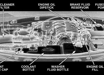
Adding Washer Fluid The fluid reservoir for the windshield washers and the rear window washer is shared. It is located in the front of the engine compartment, and should be checked for fluid level at regular intervals. Fill the reservoir with wind- shield washer solvent (not radiator antifreeze) and oper- ate the system for a few seconds to flush out the residual water. Rear Window Defroster — If Equipped
The push-button is located on the bottom of the blower con- trol knob. Press this button to turn on the rear window de- froster, and the optional elec- tric remote control heated mirrors. An light shows that the defroster is on.
amber
UNDERSTANDING THE FEATURES OF YOUR VEHICLE 159
The defroster will automatically turn off after about ten minutes. For five more minutes of operation, press the switch again. To prevent excessive battery drain, use the defroster only when the engine is operating.
CAUTION!
Use care when washing the inside of the rear window to prevent damage to heating elements. Use a soft cloth and a mild washing solution, wiping parallel to the heating elements. Also, keep all objects a safe distance from the window to prevent damaging the heating elements.
160 UNDERSTANDING THE FEATURES OF YOUR VEHICLE
ROOF LUGGAGE RACK— NON FUNCTIONAL The tie loops provided in the Roof Ditch Applique can be used to help tie down cargo; however, metal rails/ crossbars should always be used whenever cargo is placed on the roof. Tie loops should not be used on their own to attach luggage to the Roof Ditch Applique. The load carried on the roof, when equipped with a luggage rack, must not exceed 150 lbs (68 kg), and it should be uniformly distributed over the cargo area. Check the straps frequently to be sure that the load remains securely attached. NOTE: Metal rails/crossbars are offered by Mopart accessories. See your authorized dealer. External racks do not increase the total load carrying capacity of the vehicle. Be sure that the total occupant and luggage load inside the vehicle, plus the load on the luggage rack, do not exceed the maximum vehicle load capacity.
CAUTION!
To avoid damage to the roof rack and vehicle, do not exceed the maximum roof rack load capacity. Always distribute heavy loads as evenly as possible and secure the load appropriately. Long loads, which extend over the windshield, such as wood panels or surfboards, should be secured to both the front and rear of the vehicle. Place a blanket or other protection between the surface of the roof and the load. Travel at reduced speeds and turn corners carefully when carrying large or heavy loads on the roof rack. Wind forces, due to natural causes or nearby truck traffic, can add sudden upward loads. This is espe- cially true on large flat loads and may result in damage to the cargo or your vehicle.
WARNING!
Cargo must be securely tied before driving your vehicle. Improperly secured loads can fly off the vehicle, particularly at high speeds, resulting in per- sonal injury or property damage. Follow the roof rack Cautions when carrying cargo on your roof rack.
UNDERSTANDING THE FEATURES OF YOUR VEHICLE 161
INSTRUMENT PANEL AND CONTROLS
CONTENTS
m Instrument Panel And Controls . . . . . . . . . . . . . 166
m Instrument Cluster . . . . . . . . . . . . . . . . . . . . . . 167
m Instrument Cluster Description . . . . . . . . . . . . . 168
m Compass And Trip Computer — If Equipped . . . 180
N Control Buttons . . . . . . . . . . . . . . . . . . . . . . 181
N Trip Conditions . . . . . . . . . . . . . . . . . . . . . . . 182
N Compass/Temperature Display . . . . . . . . . . . 182m Electronic Vehicle Information Center (EVIC) —
If Equipped . . . . . . . . . . . . . . . . . . . . . . . . . . . 184
N Electronic Vehicle Information Center (EVIC)
Displays . . . . . . . . . . . . . . . . . . . . . . . . . . . . 186
N Oil Change Required . . . . . . . . . . . . . . . . . . . 187
N Trip Functions . . . . . . . . . . . . . . . . . . . . . . . 188
N Compass Display . . . . . . . . . . . . . . . . . . . . . 189
N Telephone — If Equipped . . . . . . . . . . . . . . . 191
N Personal Settings (Customer ProgrammableFeatures)
. . . . . . . . . . . . . . . . . . . . . . . . . . . 193
m Radio General Information . . . . . . . . . . . . . . . . 196
N Radio Broadcast Signals . . . . . . . . . . . . . . . . . 196164 INSTRUMENT PANEL AND CONTROLS
N Two Types Of Signals . . . . . . . . . . . . . . . . . . 196
N Electrical Disturbances . . . . . . . . . . . . . . . . . . 196
N AM Reception . . . . . . . . . . . . . . . . . . . . . . . 197
N FM Reception . . . . . . . . . . . . . . . . . . . . . . . . 197m Sales Code REQ — AM/FM Stereo Radio And
6–Disc CD/DVD Changer (MP3/WMA AUX Jack) . . . . . . . . . . . . . . . . . . . . . . . . . . . . . . . . 197
N Operating Instructions - Radio Mode . . . . . . . 198
N Operation Instructions - (Disc Mode For CDAnd MP3/WMA Audio Play, DVD-Video) . . . . 206
N Notes On Playing MP3/WMA Files . . . . . . . . 208
N List Button (Disc Mode For MP3/WMAPlay)
. . . . . . . . . . . . . . . . . . . . . . . . . . . . . . 210
N Info Button (Disc Mode For MP3/WMA
Play)
. . . . . . . . . . . . . . . . . . . . . . . . . . . . . . 210
m Sales Code RES — AM/FM Stereo Radio With
CD Player (MP3 AUX Jack) . . . . . . . . . . . . . . . . 213
N Operating Instructions - Radio Mode . . . . . . . 213
N Operation Instructions - CD Mode For CDAnd MP3 Audio Play . . . . . . . . . . . . . . . . . . 219
N Notes On Playing MP3 Files . . . . . . . . . . . . . 221
N List Button (CD Mode For MP3 Play) . . . . . . . 224
N Info Button (CD Mode For MP3 Play) . . . . . . . 224m Sales Code RER — AM/FM/CD/DVD Radio
With Navigation System — If Equipped . . . . . . . 225
N Operating Instructions — Satellite Radio . . . . . 226
N Clock Setting Procedure . . . . . . . . . . . . . . . . . 226m Satellite Radio (RSC) — If Equipped
(RER/REQ/REN Radios Only)
. . . . . . . . . . . . . 227
N System Activation . . . . . . . . . . . . . . . . . . . . . 227
N Electronic Serial Number/Sirius IdentificationNumber (ENS/SID) . . . . . . . . . . . . . . . . . . . . 228
N Selecting Satellite Mode . . . . . . . . . . . . . . . . . 228
N Satellite Antenna . . . . . . . . . . . . . . . . . . . . . . 228
N Reception Quality . . . . . . . . . . . . . . . . . . . . . 228
N Operating Instructions - Satellite Mode . . . . . . 229
N Operating Instructions - Hands Free Phone(If Equipped)
. . . . . . . . . . . . . . . . . . . . . . . . 231
N Operating Instructions - Video Entertainment
System (VES™) (If Equipped) . . . . . . . . . . . . . 231
INSTRUMENT PANEL AND CONTROLS 165
m Video Entertainment System (Sales Code XRV) —
If Equipped . . . . . . . . . . . . . . . . . . . . . . . . . . . 231
m Remote Sound System Controls — If Equipped . . 233
N Radio Operation . . . . . . . . . . . . . . . . . . . . . . 233
N CD Player . . . . . . . . . . . . . . . . . . . . . . . . . . 234
m CD/DVD Disc Maintenance . . . . . . . . . . . . . . . 234
m Climate Controls . . . . . . . . . . . . . . . . . . . . . . . 235N Manual Air Conditioning And Heating
System . . . . . . . . . . . . . . . . . . . . . . . . . . . . . 235
N Operating Tips . . . . . . . . . . . . . . . . . . . . . . . 239166 INSTRUMENT PANEL AND CONTROLS
INSTRUMENT PANEL AND CONTROLS
1 — Air Outlet 2 — Instrument Cluster
3 — Storage Tray 4 — Center Air Outlet 5 — Radio
6 — Glove Box 7 — Climate Control
8 — * Heated Seat Switch 9 — * Rear Park Assist Switch 10 — Passenger Airbag Disable Light
11 — Hazard Warning Flasher 12 — * Electronic Stability Control / Traction Control Switch 13 — Cigar Lighter / Power Outlet 14 — Storage Bin * — If Equipped
INSTRUMENT CLUSTER
INSTRUMENT PANEL AND CONTROLS 167
168 INSTRUMENT PANEL AND CONTROLS
INSTRUMENT CLUSTER DESCRIPTION
1. Fuel Gauge
The fuel gauge shows level of fuel in tank when ignition switch is in the ON position.
2. Fuel Cap Indicator
This symbol indicates the side of the vehicle where the fuel cap is located.
3. Temperature Gauge
The temperature gauge indicates engine coolant temperature. Any reading within the normal range indicates that the cooling system is operat- ing satisfactorily. The gauge needle will likely indicate a high temperature when driving in hot weather, up moun- tain grades, in heavy traffic, or when towing a trailer. If the needle rises to the “H” mark, stop the vehicle, shift
into N (Neutral) increase engine speed for 2-3 minutes. If the temperature reading does not return to normal, seek authorized service immediately.
CAUTION!
Do not leave your vehicle unattended with the en- gine running as you would not be able to react to the temperature indicator if the engine overheats.
The gauge pointer will remain near its last reading when the engine is turned off. It will return to a true reading when the engine is restarted. 4. Low Fuel Warning Light
This indicator lights when the fuel gauge reads 1/8
of a tank or less.5. Seat Belt Reminder Light
This light comes on for several seconds after the ignition is turned ON as a reminder to “buckle up.” This light will remain on as long as the driver or passengers seat belt remains unbuckled. If the seat belt indicator remains on and/or flashes with belts buckled, this may indicate a fault in the seat belt reminder system. Have the system checked by an authorized dealer. 6. Coolant Temperature Warning Light
This light warns of an overheated engine condi- tion. For a bulb check, this light will come on momentarily when the ignition is turned On. If the light turns on while driving, stop the vehicle, shift into N (Neutral) and increase the engine speed for 2 to 3
minutes. If the temperature reading does not return to normal, seek authorized service immediately.INSTRUMENT PANEL AND CONTROLS 169
As temperatures rise and the gauge approaches 9H9, this indicator will illuminate and a single chime will sound after reaching a set threshold. Further overheating will cause the temperature gauge to pass 9H9, the indicator will continuously flash, and a continuous chime will occur until the engine is allowed to cool.
CAUTION!
Driving with a hot engine cooling system could damage your vehicle. If the temperature light is on, safely pull over and stop the vehicle. Idle the vehicle in neutral with the air conditioner turned off until the light turns off. If the if the light remains on, turn the engine off immediately, and call for service.
170 INSTRUMENT PANEL AND CONTROLS
WARNING!
A hot engine cooling system is dangerous. You or others could be badly burned by steam or boiling coolant. You may want to call a service center if your vehicle overheats. If you decide to look under the hood yourself, see Section 7 of this manual. Follow the warnings under the Cooling System Pressure Cap paragraph.
7. Speedometer Shows the vehicles speed. 8. High Beam Indicator Light
Indicates that headlights are on high beam.
9. Security Alarm System Indicator Light — If Equipped This light will flash rapidly for approximately 15 seconds when the vehicle theft alarm is arming. The light will flash at a slower speed continuously after the alarm is set. The security light will also come on for about three seconds when the ignition is first turned on. 10. Electronic Stability Program (ESP) Warning Light/Brake Assist System (BAS) Warning Light – If Equipped
The malfunction lamp for the ESP is combined with BAS. The yellow “ESP/BAS Warning Lamp” and the yellow “ESP/TCS Indicator Light” in the instrument cluster both come on when the ignition switch is turned to the “ON” position. They should go out with the engine running. If the “ESP/BAS Warning Lamp” comes on continuously with the engine running, a malfunction has been detected in either the ESP or the BAS system. If this light remains on
after several ignition cycles, and the vehicle has been driven several miles at speeds greater than 30 mph (48
km/h), see your authorized dealer as soon as possible. NOTE: The 9ESP/TCS Indicator Light9 and the 9ESP/ BAS Warning Lamp9 come on momentarily each time the ignition switch is turned ON. The ESP Control System will make buzzing or clicking sounds when it is actively operating. 11. TOW/HAUL Indicator Light — If EquippedThe TOW/HAUL button is located on the gear shift bezel. This light will illuminate when the TOW/HAUL button has been selected.
12. Turn Signal Indicator Light
When a turn signal is activated, a right-pointing or left-pointing arrow lights up and flashes to indicate the direction of the turn. These indicators also indicate proper operation of the front and rear turn signal lights.
INSTRUMENT PANEL AND CONTROLS 171
If either indicator flashes at a faster rate than normal, check for a defective bulb. If either indicator fails to light up when the lever is moved, check for a defective turn signal LED. A single chime is activated when the left/ right turn signal is left on with the engine RPM vehicle speed greater than 15 mph (24 km/h) for more than one mile. 13. Transmission Temperature Warning Light — If Equipped
This light indicates that there is excessive trans- mission fluid temperature that might occur with severe usage such as trailer towing. If this light comes on, stop the vehicle and run the engine at idle or faster, with the transmission in N (Neutral) until the light goes off. 14. Brake Warning Light The red “BRAKE” warning light will come on when the ignition key is first turned on, and stay on briefly as a
172 INSTRUMENT PANEL AND CONTROLS
bulb check. If the bulb does not come on during starting, see your authorized dealer for service. If the light stays on, it may be an indication that the parking brake has not been released, or there is a low brake fluid level. If the light remains on when the parking brake has been disengaged, and the fluid level is at the full mark on the master cylinder reservoir, it indicates a possible brake hydraulic system malfunction or a problem with the Brake Booster. In this case, the light will remain on until the condition has been corrected. If the problem is related to the brake Booster the ABS pump will run when applying the brake. The “BRAKE” warning light will flash whether or not it is in gear, if the park brake is applied, and the engine is running (manual transmission only). The “BRAKE” warning light will remain on steady with the park brake on and the shifter in the P (Park) position. If shifted out of P (Park), it will begin to flash (automatic transmission only).
If brake failure is indicated, immediate repair is neces- sary. Operating the vehicle in this condition is danger- ous!
15. Electronic Throttle Control (ETC) Warning Light — If Equipped
This light informs you of a problem with the Electronic Throttle Control system. If a prob- lem is detected the light will come on while the engine is running. If the light remains lit with the engine running your vehicle will usually be drivable, however, see your dealer for service as soon as possible. If the light is flashing when the engine is running, immediate service is required and you may experience reduced performance, an elevated/rough idle or engine stall and your vehicle may require towing. The light will come on when the ignition is first turned on and remain on for 15 seconds as a bulb check. If the light does not come on during starting, have the system checked by an authorized dealer.
16. Electronic Stability Program (ESP) Indicator Light/Traction Control System (TCS) Indicator Light
The yellow ESP indicator light in the speedom- eter area illuminates with the key in the igni- tion switch turned to the ON/RUN position. It should go out with the engine running. The 9ESP/TCS Indicator Light9 starts to flash as soon as the tires lose traction and the ESP system becomes active. The 9ESP/TCS Indicator Light9 also flashes when TCS is active. If the 9ESP/TCS Indicator Light9 begins to flash during acceleration, ease up on the accelerator and apply as little throttle as possible. Be sure to adapt your speed and driving to the prevailing road conditions. The “ESP/ TCS Indicator Light” becomes illuminated when the ESP-Off button has been pressed or ESP is only partially available caused by lack of engine management or brake thermal model.
INSTRUMENT PANEL AND CONTROLS 173
17. Voltage Warning Light
This light monitors the electrical system voltage. The light should turn on momentarily as the engine is started. If the light stays on or turns on while driving, it indicates a problem with the charging system. Immediate service should be obtained. 18. SERV (Service) 4WD Indicator Light — If Equipped The “SERV 4WD Indicator Light” will come on when the ignition key is turned to the ON position and will stay on for 2 seconds. If the light stays on or comes on during driving, it means that the 4WD system is not functioning properly and that service is required. 19. Anti-Lock Brake Warning Light
This light monitors the Anti-Lock Brake System which is described elsewhere in this manual. This light will come on when the ignition key is turned to the ON position and may stay on for
174 INSTRUMENT PANEL AND CONTROLS
approximately 3 seconds. If this light remains on or comes on during driving, it indicates that the Anti-Lock portion of the brake system is not functioning and that service is required. See your authorized dealer immedi- ately. With the ABS malfunctioning, the BAS and ESP are also switched off. Both malfunction indicator lights illu- minate with the engine running. If the charging voltage falls below 10 volts, the malfunction indicator light illuminates and the ABS is switched off. When the voltage is above this value again, the malfunction indi- cator light should go out and the ABS is operational. If the malfunction indicator light stays illuminated, have the system checked at your authorized dealer as soon as possible. 20. Front Fog Light Indicator Light — If Equipped This light shows when the fog lights are ON.
21. Oil Pressure Warning Light
This light indicates that the engine oil pressure has become too low. For a bulb check, this light will come on momentarily when the ignition is turned On. If the light turns on while driving, stop the vehicle and shut off the engine as soon as possible. Immediate service should be obtained. 22. Airbag Warning Light
The indicator lights and remains lit for 6 to 8
seconds when the ignition is first turned ON. If the light does not come on when the ignition is first turned on, or the light stays on or comes on while driving, have the airbag system checked by an authorized dealer. 23. Tachometer This gauge measures engine revolutions-per-minute (rpm x 1000).24. Transmission Range Indicator The electronic gear selector display is self-contained within the instrument cluster. It displays the position of the automatic transmission shift lever, and the relation of each position to all other positions. For a good signal the display will place a box around the selected transmission range (PRND21). If the PRNDL displays only the char- acters PRND21 (no boxes) have the system checked by an authorized dealer. 25. Tire Pressure Monitoring Telltale Light — If Equipped
Each tire, including the spare (if provided), should be checked monthly when cold and inflated to the inflation pressure recommended by the vehicle manufacturer on the vehicle placard or tire inflation pressure label. (If your vehicle has tires of a different size than the size indicated on the
INSTRUMENT PANEL AND CONTROLS 175
vehicle placard or tire inflation pressure label, you should determine the proper tire inflation pressure for those tires.) As an added safety feature, your vehicle has been equipped with a tire pressure monitoring system (TPMS) that illuminates a low tire pressure telltale when one or more of your tires is significantly under-inflated. Accord- ingly, when the low tire pressure telltale illuminates, you should stop and check your tires as soon as possible, and inflate them to the proper pressure. Driving on a signifi- cantly under-inflated tire causes the tire to overheat and can lead to tire failure. Under-inflation also reduces fuel efficiency and tire tread life, and may affect the vehicle’s handling and stopping ability. Please note that the TPMS is not a substitute for proper tire maintenance, and it is the driver’s responsibility to
176 INSTRUMENT PANEL AND CONTROLS
maintain correct tire pressure, even if under-inflation has not reached the level to trigger illumination of the TPMS low tire pressure telltale. Your vehicle has also been equipped with a TPMS malfunction indicator to indicate when the system is not operating properly. The TPMS malfunction indicator is combined with the low tire pressure telltale. When the system detects a malfunction, the telltale will flash for approximately one minute and then remain continuously illuminated. This sequence will continue upon subse- quent vehicle start-ups as long as the malfunction exists. When the malfunction indicator is illuminated, the sys- tem may not be able to detect or signal low tire pressure as intended. TPMS malfunctions may occur for a variety of reasons, including the installation of replacement or alternate tires or wheels on the vehicle that prevent the TPMS from functioning properly. Always check the TPMS malfunction telltale after replacing one or more
tires or wheels on your vehicle to ensure that the replace- ment or alternate tires and wheels allow the TPMS to continue to function properly.
CAUTION!
The TPMS has been optimized for the original equipment tires and wheels. TPMS pressures and warnings have been established for the tire size equipped on your vehicle. Undesirable system opera- tion or sensor damage may result when using re- placement equipment that is not of the same size, type, and/or style. Aftermarket wheels can cause sensor damage. Do not use aftermarket tire sealants or balance beads if your vehicle is equipped with a TPMS, as damage to the sensors may result.
26. Odometer/Trip Odometer The odometer shows the total distance the vehicle has been driven. The trip odometer shows individual trip mileage. To toggle between the odometer and the trip odometer, press the Odometer/Trip Odometer Button. To reset the Trip Odometer, press and hold the button while in trip mode, until the Trip Odometer resets. If the vehicle diagnostic system determines that the fuel filler cap is loose, improperly installed, or damaged, GASCAP will be displayed in the instrument cluster. Tighten the fuel filler cap properly and press the odom- eter reset button to turn the GASCAP message off. If the problem continues, the message will appear the next time the vehicle is started. U.S. federal regulations require that upon transfer of vehicle ownership, the seller certify to the purchaser the
INSTRUMENT PANEL AND CONTROLS 177
correct mileage that the vehicle has been driven. There- fore, if the odometer reading is changed during repair or replacement, be sure to keep a record of the reading before and after the service so that the correct mileage can be determined. Change Oil Message Your vehicle is equipped with an engine oil change indicator system. The “Change Oil” message will flash in the instrument cluster odometer for approximately 12
seconds after a single chime has sounded to indicate the next scheduled oil change interval. The engine oil change indicator system is duty cycle based, which means the engine oil change interval may fluctuate dependent upon your personal driving style. Unless reset, this message will continue to display each time you turn the ignition switch to the ON/RUN position. To turn off the message temporarily, press and release the Trip Odometer button178 INSTRUMENT PANEL AND CONTROLS
on the instrument cluster. To reset the oil change indica- tor system (after performing the scheduled maintenance) refer to the following procedure.
1. Turn the ignition switch to the ON position (Do not start the engine). 2. Fully depress the accelerator pedal slowly three times within 10 seconds. 3. Turn the ignition switch to the OFF/LOCK position. If the indicator message illuminates when you NOTE: start the vehicle, the oil change indicator system did not reset. If necessary repeat this procedure.
27. Malfunction Indicator Light
This light is part of an onboard diagnostic system which monitors the emissions and engine control system. If the vehicle is ready for emissions testing the light will come on when the ignition is first turned on and remain on, as a bulb check, until the engine is started. If the vehicle is not ready for emissions testing the light will come on when the ignition is first turned on and remain on for 15 seconds, then blink for 10
seconds, and remain on until the vehicle is started. If the bulb does not come on during starting, have the condi- tion investigated promptly. If this light comes on and remains on while driving, it suggests a potential engine control problem and the need for system service. Although your vehicle will usually be drivable and not need towing, see your dealer for service as soon as possible.CAUTION!
Prolonged driving with the MIL on could cause damage to the engine control system. It also could affect fuel economy and driveability. If the MIL is flashing, severe catalytic converter damage and power loss will soon occur. Immediate service is required.
28. Cruise Indicator Light — If Equipped This indicator lights when the electronic speed control system is turned on. 29. Odometer/Trip Odometer Reset Button Press this button to change the display from odometer to either of the two trip odometer settings. When the trip odometer is displayed, press once for Trip A, and press again for Trip B. If the instrument cluster is a base cluster
INSTRUMENT PANEL AND CONTROLS 179
(no separate compass/temperature display), press the button a third time for outside Ambient Temperature on the odometer display. Press and hold the button for two seconds to reset the trip odometer to 0 miles or kilome- ters. The odometer must be in trip mode to reset. Press this button to view the compass display (if equipped). Refer to “Compass/Trip Computer” in this section. 30. Compass/Trip Computer or Electronic Vehicle Information Center (EVIC) Display—If Equipped this display When the appropriate conditions exist, shows the Compass/Trip Computer or Electronic Vehicle Information Center (EVIC) messages.
180 INSTRUMENT PANEL AND CONTROLS
COMPASS AND TRIP COMPUTER — IF EQUIPPED The Compass/Trip Computer a driver- interactive display (displays information on outside tem- perature, compass direction, and trip information). It is located on the lower left part of the cluster below the fuel and engine temperature gauge, and the tachometer.
features
Compass/Trip Computer Display
The compass/trip computer, when the appropriate con- ditions exist, will show the following messages in the odometer display: † Door Ajar (door) † Lift Gate Ajar (gATE)
† Loose Fuel Cap (gASCAP) These messages can be manually turned off by pressing the right button (on the instrument cluster). Control Buttons Press and release the odometer/trip odometer reset but- ton (right side of the instrument cluster) to access the compass/trip computer displays.
INSTRUMENT PANEL AND CONTROLS 181
Display Button
182 INSTRUMENT PANEL AND CONTROLS
Trip Conditions
Compass/Temperature Display
Trip Odometer (ODO) This display shows the distance traveled since the last reset. Press and release the right button (on the instru- ment cluster) to switch from odometer, to trip A or trip B. Press and hold the right button while the odometer/trip odometer is displayed to reset. Trip A Shows the total distance traveled for trip A since the last reset. Trip B Shows the total distance traveled for trip B since the last reset.
Compass Variance Compass Variance is the difference between magnetic North and Geographic North. In some areas of the country, the difference between magnetic and geographic North is great enough to cause the compass to give false readings. In order to ensure compass accuracy, the com- pass variance should be properly set according to the compass variance map zone that the vehicle is in.
INSTRUMENT PANEL AND CONTROLS 183
NOTE: Magnetic materials should be kept away from the top of the right rear quarter window. This is where the compass sensor is located. To Set the Variance Start the engine, and leave the transmission in the P (Park) position. Press and hold (approximately ten sec- onds) the odometer/trip odometer reset button until the current variance zone number is displayed. To change the zone, press and release the odometer/trip odometer reset button to increment the variance one step. Repeat as necessary, until the desired variance is achieved. NOTE: The factory default zone is 8. During program- ming, the zone value will wrap around from zone 15 to zone 1. Compass Calibration If the compass appears erratic, inaccurate or abnormal, you may wish to calibrate the compass. Prior to calibrat- ing the compass make sure the proper zone is selected.
184 INSTRUMENT PANEL AND CONTROLS
To Manually Calibrate the Compass Start the engine, and leave the transmission in the P (Park) position. Press and hold (approximately 10 sec- onds) the odometer/trip odometer reset button until the current variance zone number is displayed. Release the odometer/trip odometer reset button, then press and hold again (approximately 10 seconds), until the direc- tion is displayed with the “CAL” indicator on continu- ously in the display. To complete the compass calibration, drive the vehicle in one or more complete 360 degree circles under 5 mph (8 km/h) in an area free from power lines, large metallic objects, until the “CAL” indicator turns off. The compass will now function normally.
ELECTRONIC VEHICLE INFORMATION CENTER (EVIC) — IF EQUIPPED The Electronic Vehicle Information Center (EVIC) fea- tures a driver-interactive display. It is located on the instrument cluster in the lower half of the fuel/coolant temperature gauge.
Vehicles equipped with steering wheel mounted buttons (described in this section) are also equipped with the EVIC. The EVIC consists of the following: † System Status † Vehicle information warning message displays † Tire Pressure Monitor System (If Equipped) † Personal Settings (Customer Programmable Features) † Compass display † Outside temperature display † Trip computer functions † UConnect™ hands-free communication system dis- † Navigation system screens (If Equipped) † Audio mode display
plays (If Equipped)
INSTRUMENT PANEL AND CONTROLS 185
The system allows the driver to select information by pressing the following buttons mounted on the steering wheel:
Press and release the MENU button and the mode displayed will change between Trip Functions, Navigation (if equipped), System Status, Personal Settings, and Telephone (if equipped). Press the FUNCTION SELECT button to accept a selection. Also, the FUNCTION SELECT but- ton changes the current CD track being played (if so equipped) when the EVIC is in the Compass/Temp/Audio screen. Press the SCROLL button to scroll through Trip Functions, Navigation (if equipped), System Status Messages, and Personal Settings (Cus- tomer Programmable Features).
186 INSTRUMENT PANEL AND CONTROLS
Press and release the COMPASS/TEMPERATURE button to display one of eight compass readings and the outside temperature.
Electronic Vehicle Information Center (EVIC) Displays When the appropriate conditions exist, the Electronic Vehicle Information Center (EVIC) displays the following messages: † Turn Signal On (with a continuous warning chime) † Left Front Turn Signal Light Out (with a single chime) † Left Rear Turn Signal Light Out (with a single chime) † Right Front Turn Signal Light Out (with a single † Right Rear Turn Signal Light Out (with a single chime) † RKE Battery Low (with a single chime)
chime)
chime if speed is above 1 mph)
chime if speed is above 1 mph)
† Personal Settings Not Available – Vehicle Not in Park † Left/Right Front Door Ajar (one or more, with a single † Left/Right Rear Door Ajar (one or more, with a single † Door(s) Ajar (with a single chime if vehicle is in † Liftgate Ajar (with a single chime) † Left Front Low Pressure (with a single chime). Refer to “Tire Pressure Monitoring System” in Section 5 of this manual. † Left Rear Low Pressure (with a single chime). Refer to “Tire Pressure Monitoring System” in Section 5 of this manual.
motion)
† Right Front Low Pressure (with a single chime). Refer to “Tire Pressure Monitoring System” in Section 5 of this manual. † Right Rear Low Pressure (with a single chime). Refer to “Tire Pressure Monitoring System” in Section 5 of this manual. † Check TPM System (with a single chime). Refer to “Tire Pressure Monitoring System” in Section 5 of this manual. † Check Gascap (refer to “Adding Fuel” in Section 5 of † Oil Change Required (with a single chime).
this manual for more details)
INSTRUMENT PANEL AND CONTROLS 187
Oil Change Required Your vehicle is equipped with an engine oil change indicator system. The “Oil Change Required” message will flash in the EVIC display for approximately 10
seconds after a single chime has sounded to indicate the next scheduled oil change interval. The engine oil change indicator system is duty cycle based, which means the engine oil change interval may fluctuate dependent upon your personal driving style. Unless reset, this message will continue to display each time you turn the ignition switch to the ON/RUN position. To turn off the message temporarily, press and release the Menu button. To reset the oil change indicator system (after performing the scheduled maintenance) refer to the following procedure. 1. Turn the ignition switch to the ON position (Do not start the engine). 2. Fully depress the accelerator pedal slowly three times within 10 seconds.188 INSTRUMENT PANEL AND CONTROLS
3. Turn the ignition switch to the OFF/LOCK position. If the indicator message illuminates when you NOTE: start the vehicle, the oil change indicator system did not reset. If necessary repeat this procedure. Trip Functions Press and release the MENU button until one of the following Trip Functions displays in the EVIC: † Average Fuel Economy † Distance To Empty † Elapsed Time † Display Units of Measure in Press the SCROLL button to cycle through all the Trip Computer functions. The Trip Functions mode displays the following informa- tion:
† Average Fuel Economy Shows the average fuel economy since the last reset. When the fuel economy is reset, the display will read “RESET” or show dashes for two seconds. Then, the history information will be erased, and the averaging will continue from the last fuel average reading before the reset. † Distance To Empty (DTE) Shows the estimated distance that can be traveled with the fuel remaining in the tank. This estimated distance is determined by a weighted average of the instantaneous and average fuel economy, according to the current fuel tank level. DTE cannot be reset through the FUNCTION SELECT button. NOTE: Significant changes in driving style or vehicle loading will greatly affect the actual drivable distance of the vehicle, regardless of the DTE displayed value.
† When the DTE value is less than 30 miles (48 km) estimated driving distance, the DTE display will change to a text display of 9LOW FUEL.9 This display will continue until the vehicle runs out of fuel. Adding a significant amount of fuel to the vehicle will turn off the 9LOW FUEL9 text and a new DTE value will display.
† Elapsed Time Shows the total elapsed time of travel since the last reset when the ignition switch is in the ACC position. Elapsed time will increment when the ignition switch is in the ON or START position. † Display Units of Measure in: To make your selection, press and release the FUNC- TION SELECT button until “US” or “METRIC” appears. To Reset The Display Reset will only occur while a resettable function is being displayed. Press and release the FUNCTION SELECT
INSTRUMENT PANEL AND CONTROLS 189
button once to clear the resettable function being dis- played. To reset all resettable functions, press and release the FUNCTION SELECT button a second time within 3
seconds of resetting the currently displayed function (>Reset ALL will display during this 3 second window). Compass DisplayThe compass readings indicate the direction the vehicle is facing. Press and release the compass button to display one of eight com- pass readings and the outside temperature.
Automatic Compass Calibration This compass is self-calibrating, which eliminates the need to manually reset the compass. When the vehicle is new, the compass may appear erratic and the EVIC will display “CAL” until the compass is calibrated. You may also calibrate the compass by completing one or more 360° turns (in an area free from large metal or metallic
190 INSTRUMENT PANEL AND CONTROLS
objects) until the “CAL” indicator displayed in the EVIC turns off. The compass will now function normally. Manual Compass Calibration If the compass appears erratic and the “CAL” indicator does not appear in the EVIC display, you must put the compass into the Calibration Mode manually as follows: 1. Turn on the ignition switch. 2. Press the MENU button until Personal Settings (Cus- tomer Programmable Features) menu is reached. 3. Press the SCROLL button until “Calibrate Compass” is displayed in the EVIC. 4. Press and release the FUNCTION SELECT button to start the calibration. The “CAL” indicator will be dis- played in the EVIC.
5. Complete one or more 360° turns (in an area free from large metal or metallic objects) until the “CAL” indicator turns off. The compass will now function normally. Compass Variance Compass Variance is the difference between magnetic North and Geographic North. In some areas of the country, the difference between magnetic and geographic North is great enough to cause the compass to give false readings. For the most accurate compass performance, the compass variance must be set using the following procedure: NOTE: Magnetic materials should be kept away from the top of the right rear quarter window. This is where the compass sensor is located.
INSTRUMENT PANEL AND CONTROLS 191
1. Turn the ignition switch ON. 2. Press and hold the compass button for approximately 2 seconds. 3. Press the SCROLL button until “Compass Variance” message and the last variance zone number displays in the EVIC. 4. Press and release FUNCTION SELECT button until the proper variance zone is selected according to the map. 5. Press and release the compass button to exit. Telephone — If Equipped Press and release the MENU button until “Telephone” displays in the EVIC. When the appropriate conditions exist, the EVIC pro- vides the following telephone information:
192 INSTRUMENT PANEL AND CONTROLS
† Phone status:
idle, voice mail,
roaming, battery strength, and signal strength in increments of 20
percent. † Call status: Incoming call, connecting, connected, air time in minutes and seconds, call ended, call failed, roaming, and no phone connection.† UConnect Active. † Caller ID phone number display. When the appropriate conditions exist, and if supported by the cell phone, the EVIC will display the following telephone symbols:
The EVIC displays this symbol to indicate the signal strength of the UConnect™ phone. The number of horizontal bars increases as the strength of the UConnect™ phone signal in- creases.
Signal Strength
The EVIC displays this symbol to indicate an incoming call.
The EVIC displays this symbol to indicate that the UConnect™ phone is currently in analog mode.
The EVIC displays this symbol to indicate that the UConnect™ phone is currently roaming.
Incom- ing Call
Analog
Roam-
ing
The EVIC displays this symbol to indicate that you have voice mail.
The EVIC displays this symbol to indicate that a phone connection has been made.
INSTRUMENT PANEL AND CONTROLS 193
The EVIC displays this symbol to indicate a text message.
The EVIC displays this symbol to indicate that the Connect™ phone is currently not available.
Call in Progress
The EVIC displays this symbol to indicate the battery strength of the UConnect™ phone.
Phone Not Avail- able
Personal Settings (Customer Programmable Features) Personal Settings allows the driver to set and recall features when the transmission is in PARK. Press and release the MENU button until Personal Set- tings displays in the EVIC.
Voice Mail
Text
Message
Battery Strength
194 INSTRUMENT PANEL AND CONTROLS
Use the SCROLL button to display one of the following choices: Language When in this display you may select one of five lan- guages for all display nomenclature, including the trip functions and the navigation system (if equipped). Press the FUNCTION SELECT button while in this display to select English, Espanol, or Francais. Then, as you con- tinue, the information will display in the selected lan- guage. NOTE: The EVIC will not change the UConnect™ language selection. Please refer to “Language Selection” in the HANDS–FREE COMMUNICATION (UConnect™) section of this manual for details. Lock Doors Automatically at 15 mph (24 km/h) When ON is selected, all doors will lock automatically when the vehicle reaches a speed of 15 mph (24 km/h). To make your selection, press and release the FUNC- TION SELECT button until “ON” or “OFF” appears.
Unlock Doors Automatically on Exit When ON is selected, all doors will unlock when the vehicle is stopped and the transmission is in the P (Park) or N (Neutral) position and the driver’s door is opened. To make your selection, press and release the FUNC- TION SELECT button until “ON” or “OFF” appears. Remote Key Unlock When Driver Door 1st Press is selected, only the driver’s door will unlock on the first press of the remote keyless entry unlock button. When Driver Door 1st Press is selected, you must press of the remote keyless entry unlock button twice to unlock the passenger’s doors. When All Doors 1st Press is selected, all of the doors will unlock on the first press of the remote keyless entry unlock button. To make your selection, press and release the FUNCTION SELECT button until “Driver Door 1st Press” or “All Doors 1st Press” appears.
Sound Horn with Remote Key Lock When ON is selected, a short horn sound will occur when the remote keyless entry “Lock” button is pressed. This feature may be selected with or without the flash lights on lock/unlock feature. To make your selection, press and release the FUNCTION SELECT button until “ON” or “OFF” appears. Flash Lights with Remote Key Lock When ON is selected, the front and rear turn signals will flash when the doors are locked or unlocked with the remote keyless entry transmitter. This feature may be selected with or without the sound horn on lock feature selected. To make your selection, press and release the FUNCTION SELECT button until “ON” or “OFF” appears. Delay Turning Headlights Off When this feature is selected, the driver can choose to have the headlights remain on for 0, 30, 60, or 90 seconds
INSTRUMENT PANEL AND CONTROLS 195
when exiting the vehicle. To make your selection, press and release the FUNCTION SELECT button until “0,” “30,” “60,” or “90” appears. Turn Headlights On with Remote Key Unlock When this feature is selected, the headlights will activate and remain on for up to 90 seconds when the doors are unlocked with the remote keyless entry transmitter. To make your selection, press and release the FUNCTION SELECT button until “OFF,” “30 sec.,” “60 sec.,” or “90
sec.” appears. Delay Power Off to Accessories Until Exit When this feature is selected, the power window switches, radio, hands–free system (if equipped), DVD video system (if equipped), power sunroof (if equipped), and power outlets will remain active for up to 60 minutes after the ignition switch is turned off. Opening a vehicle door will cancel this feature. To make your selection, press and release the FUNCTION SELECT button until “Off,” “45 sec.,” “5 min.,” or “10 min.” appears.196 INSTRUMENT PANEL AND CONTROLS
Confirmation of Voice Commands — If Equipped When ON is selected, all voice commands from the UConnect™ system are confirmed. To make your selec- tion, press and release the FUNCTION SELECT button until “ON” or “OFF” appears. Display Units of Measure in The EVIC, odometer, and navigation system (if equipped) can be changed between English and Metric units of measure. To make your selection, press and release the FUNCTION SELECT button until “US” or “METRIC” appears.
RADIO GENERAL INFORMATION
Radio Broadcast Signals Your new radio will provide excellent reception under most operating conditions. Like any system, however, car radios have performance limitations, due to mobile op- eration and natural phenomena, which might lead you to believe your sound system is malfunctioning. To help
you understand and save you concern about these “ap- parent” malfunctions, you must understand a point or two about the transmission and reception of radio sig- nals. Two Types of Signals There are two basic types of radio signals... AM or Amplitude Modulation, in which the transmitted sound causes the amplitude, or height, of the radio waves to vary... and FM or Frequency Modulation, in which the frequency of the wave is varied to carry the sound. Electrical Disturbances Radio waves may pick up electrical disturbances during transmission. They mainly affect the wave amplitude, and thus remain a part of the AM reception. They interfere very little with the frequency variations that carry the FM signal.
INSTRUMENT PANEL AND CONTROLS 197
SALES CODE REQ — AM/FM STEREO RADIO AND 6–DISC CD/DVD CHANGER (MP3/WMA AUX JACK)
NOTE: The radio sales code is located on the lower right side of your radio faceplate.
AM Reception AM sound is based on wave amplitude, so AM reception can be disrupted by such things as lightning, power lines and neon signs. FM Reception Because FM transmission is based on frequency varia- tions, interference that consists of amplitude variations can be filtered out, leaving the reception relatively clear, which is the major feature of FM radio. NOTE: The radio, steering wheel radio controls (if equipped), and 6 disc CD/DVD changer (if equipped) will remain active for up to 10 minutes after the ignition switch has been turned off. Opening a vehicle front door will cancel this feature.
REQ Radio
198 INSTRUMENT PANEL AND CONTROLS
Operating Instructions - Radio Mode
NOTE: The ignition switch must be in the ON or ACC position to operate the radio. Power Switch/Volume Control (Rotary) Press the ON/VOL control to turn the radio ON. Press the ON/VOL a second time to turn OFF the radio. Electronic Volume Control The electronic volume control turns continuously (360
degrees) in either direction without stopping. Turning the volume control to the right increases the volume and to the left decreases it. When the audio system is turned on, the sound will be set at the same volume level as last played. SEEK Buttons (Radio Mode) Press and release the SEEK buttons to search for the next listenable station in AM/FM mode. Press the right switch to seek up and the left switch to seek down. The radiowill remain tuned to the new station until you make another selection. Holding either button will bypass stations without stopping until you release it. SCAN Button (Radio Mode) Pressing the SCAN button causes the tuner to search for the next listenable station, in AM, FM or Satellite (if equipped) frequencies, pausing for 5 seconds at each listenable station before continuing to the next. To stop the search, press the SCAN button a second time. Voice Recognition Button (UConnect™ Hands Free Phone) — If Equipped Press this button to operate the Hand Free Phone (UCon- nect™) feature (if equipped). Refer to “Hands-Free Com- munication (UConnect™)” in Section 3 for more informa- tion. If your vehicle is not equipped with or this feature is not available on your vehicle, a “UConnect™ System Not Available” message will display on the radio screen.
Phone Button (UConnect™ Hands Free Phone) — If Equipped Press this button to operate the Hand Free Phone (UCon- nect™) feature (if equipped). Refer to “Hands-Free Com- munication (UConnect™)” in Section 3 for more informa- tion. If your vehicle is not equipped with or this feature is not available on your vehicle, a “UConnect™ System Not Available” message will display on the radio screen. TIME Button Press the TIME button and the time of day will display. In AM or FM mode, pressing the TIME button will switch between the time and frequency displays. Clock Setting Procedure 1. Press and hold the TIME button, until the hours blink. 2. Adjust the hours by turning the right side TUNE control knob.
INSTRUMENT PANEL AND CONTROLS 199
3. After adjusting the hours, press the right side TUNE control knob to set the minutes. The minutes will begin to blink. 4. Adjust the minutes using the right side TUNE control knob. Press the TUNE control knob to save time change. 5. To exit, press any button/knob or wait 5 seconds. The clock can also be set by pressing the SETUP button and selecting the “SET HOME CLOCK” entry. Once in this display follow the above procedure, starting at step 2. INFO Button (Radio Mode) Press the INFO button for an RDS station (one with call letters displayed). The radio will return a Radio Text message broadcast from an FM station (FM mode only).
200 INSTRUMENT PANEL AND CONTROLS
RW/FF (Radio Mode) Pressing the rewind or fast forward button causes the tuner to search for the next frequency in the direction of the arrows. This feature operates in either AM, FM or Satellite (if equipped) frequencies. TUNE Control (Radio Mode) Turn the right side rotary control clockwise to increase or counter-clockwise to decrease the frequency. Setting the Tone, Balance, and Fade Press the rotary TUNE control knob and BASS will display. Turn the TUNE control knob to the right or left to increase or decrease the Bass tones. Press the rotary TUNE control knob a second time and MID will display. Turn the TUNE control knob to the right or left to increase or decrease the Mid Range tones.
Press the rotary TUNE control knob a third time and TREBLE will display. Turn the TUNE control knob to the right or left to increase or decrease the Treble tones. Press the rotary TUNE control knob a fourth time and BALANCE will display. Turn the TUNE control knob to the right or left to adjust the sound level from the right or left side speakers. Press the rotary TUNE control knob a fifth time and FADE will display. Turn the TUNE control knob to the left or right to adjust the sound level between the front and rear speakers. Press the rotary TUNE control knob again to exit setting tone, balance, and fade. MUSIC TYPE Button (Radio Mode) Pressing this button once will turn on the Music Type mode for 5 seconds. Pressing the Music Type button or turning the TUNE control knob within 5 seconds will
allow the program format type to be selected. Many radio stations do not currently broadcast Music Type informa- tion. Toggle the Music Type button to select the following format types:
Program Type
16 Digit-Character Display
No program type or un-
defined
Adult Hits Classical
Classic Rock
College Country
Foreign Language
Information
Jazz News
None
Adlt Hit Classicl Cls Rock College Country Language
Inform Jazz News
INSTRUMENT PANEL AND CONTROLS 201
Program Type
16 Digit-Character Display
Nostalgia
Oldies
Personality
Public
Rhythm and Blues Religious Music Religious Talk
Rock Soft
Soft Rock
Soft Rhythm and Blues
Sports Talk Top 40
WeatherNostalga Oldies Persnlty Public R & B
Rel Musc Rel Talk
Rock Soft
Soft Rck Soft R&B
Sports Talk Top 40
Weather202 INSTRUMENT PANEL AND CONTROLS
By pressing the SEEK button when the Music Type icon is displayed, the radio will be tuned to the next frequency station with the same selected Music Type name. The Music Type function only operates when in the FM mode. If a preset button is activated while in the Music Type (Program Type) mode, the Music Type mode will be exited and the radio will tune to the preset station. SETUP Button Pressing the SETUP button allows you to select between the following items: NOTE: Use the Tune Control Knob to scroll through the entries. Push the Audio/Select button to select an entry and make changes.
† DVD Enter - When the disc is in DVD Menu mode, selecting DVD Enter will allow you to play the current highlighted selection. Use the remote control to scroll up and down the menu (If Equipped). † DISC Play/Pause - You can toggle between playing the DVD and pausing the DVD by pushing the SELECT button (If Equipped). † DVD Play Options - Selecting the DVD Play Options will display the following: † Subtitle – Repeatedly Pressing SELECT will switch subtitles to different subtitle languages that are available on the disc (If Equipped). † Audio Stream – Repeatedly Pressing SELECT will switch to different audio languages (if supported on the disc) (If Equipped).
† Angle – Repeatedly Pressing SELECT will change the viewing angle if supported by the DVD disc (If Equipped).
Equipped).
NOTE: The available selections for each of the above entries varies depending upon the disc. NOTE: These selections can only be made while playing a DVD. † VES Power - Allows you to turn VES ON and OFF (If † VES Lock - Locks out rear VES remote controls (If † VES CH1/CH2 - Allows the user to change mode of either the IR1 or IR2, wireless headphones, by pressing the Audio/Select button (If Equipped). † Set Home Clock - Pressing the SELECT button will allow user to set the clock. Turn the TUNE control
Equipped).
INSTRUMENT PANEL AND CONTROLS 203
knob to adjust the hours and then press and turn the TUNE control knob to adjust the minutes. Press the TUNE control knob again to save changes. † Player Defaults - Selecting this item will allow the user to scroll through the following items, and set defaults according to customer preference.
Menu Language — If Equipped Selecting this item will allow the user to choose the default startup DVD menu language (effective only if language supported by disc). If customer wishes to select a language not listed, then scroll down and select 9other.9
Enter the 4-digit country code using the TUNE control knob to scroll up and down to select the # and then push to select. Audio Language — If Equipped Selecting this item will allow the user to choose a default audio language (effective only if language supported by204 INSTRUMENT PANEL AND CONTROLS
disc). If customer wishes to select a language not listed, then scroll down and select 9other.9 Enter the country code using the TUNE control knob to scroll up and down to select the # and then push to select. Subtitle Language — If Equipped Selecting this item will allow the user to choose a default subtitle language (effective only if language supported by disc). If customer wishes to select a language not listed, then scroll down and select 9other.9 Enter the country code using the TUNE control knob to scroll up and down to select the # and then push to select. Subtitles — If Equipped Selecting this item will allow the user to choose between subtitle OFF or ON.
Audio DRC — If Equipped Selecting this item will allow the user to limit maximum audio dynamic range - The default is set to 9High,9 and under this setting, dialogues will play at 11 db higher than if the setting is 9Normal.9
Aspect Ratio — If Equipped Selecting this item will allow the user to choose between wide screen, pan scan, and letter box. AutoPlay — If Equipped When this is set to ON and a DVD video is inserted, it will bypass the DVD menu screen and automatically play the movie. In some rare cases, the DVD player may not auto play the main title. In such cases, use the menu button on the remote control to select desired title to play. NOTE: The user will have to set these defaults before loading a disc. If changes are made to these settings aftera disc is loaded, changes will not be effective. Also, the defaults are effective only if the disc supports the customer-preferred settings. AM and FM Buttons (Radio Mode) Press the buttons to select AM or FM Modes. SET Button (Radio Mode) — To Set the Push-Button Memory When you are receiving a station that you wish to commit to push-button memory, press the SET button. The symbol SET 1 will now show in the display window. Select the button (1-6) you wish to lock onto this station and press and release that button. If a button is not selected within 5 seconds after pressing the SET button, the station will continue to play but will not be stored into push-button memory. You may add a second station to each push-button by repeating the above procedure with this exception: Press the SET button twice and SET 2 will show in the display
INSTRUMENT PANEL AND CONTROLS 205
window. Each button can be set for SET 1 and SET 2 in both AM and FM. This allows a total of 12 AM, 12 FM, and 12 Satellite (if equipped) stations to be stored into push-button memory. The stations stored in SET 2
memory can be selected by pressing the push-button twice. Every time a preset button is used, a corresponding button number will display. Buttons 1 - 6 (Radio Mode) These buttons tune the Radio to the stations that you commit to push-button memory {12 AM, 12 FM, and 12
Satellite (if equipped) stations}. DISC Button Pressing the DISC button will allow you to switch from AM/FM modes to Disc modes.206 INSTRUMENT PANEL AND CONTROLS
Operation Instructions - (DISC MODE for CD and MP3/WMA Audio Play, DVD-VIDEO) The radio DVD player and many DVD discs are coded by geographic region. These region codes must match in order for the disc to play. If the region code for the DVD disc does not match the region code for the radio DVD player, it will not play the disc. Customers may take their vehicle to an authorized dealer to change the region code of the player a maximum of 5 times.
CAUTION!
The radio may shut down during extremely hot conditions. When this occurs, the radio will indicate “Disc Hot” and shut off until a safe temperature is reached. This shutdown is necessary to protect the optics of the DVD player and other radio internal components.
NOTE: The ignition switch must be in the ON or ACC position to operate the radio. LOAD Button — Loading Compact Disc(s) Press the LOAD button and the push-button with the corresponding number (1-6) where the CD is being loaded. The radio will display PLEASE WAIT and prompt when to INSERT DISC. After the radio displays 9INSERT DISC,9 insert the CD into the player. Radio display will show 9LOADING DISC9 when the disc is loading and “READING DISC” when the radio is reading the disc.
CAUTION!
† This CD player will accept 4 3/4 inch (12 cm) discs only. The use of other sized discs may damage the CD player mechanism.
Eject Button — Ejecting Compact Disc(s)
Press the eject button and the push-button with the corresponding number (1-6) where the CD was loaded and the disc will unload and move to the entrance for easy removal. Radio display will show 9EJECTING DISC9 when the disc is being ejected and prompt the user to remove the disc. Press and hold the eject button for 5 seconds and all CDs will be ejected from the radio. The disc can be ejected with the radio and ignition OFF. SEEK Button (CD MODE) Press the right SEEK button for the next selection on the CD. Press the left SEEK button to return to the beginning of the current selection, or return to the beginning of the previous selection if the CD is within the first second of the current selection. Pressing and holding the SEEK button will allow to scroll through tracks faster in CD, MP3/MWA modes.
INSTRUMENT PANEL AND CONTROLS 207
SCAN Button (CD MODE) Press the Scan button to scan through each track on the CD currently playing. TIME Button (CD MODE) Press this button to change the display from a large CD playing time display to a small CD playing time display. RW/FF (CD MODE) Press and hold FF (Fast Forward) and the CD player will begin to fast forward until FF is released or RW or another CD button is pressed. The RW (Reverse) button works in a similar manner. AM or FM Button (CD MODE) Switches the Radio to the Radio mode.
208 INSTRUMENT PANEL AND CONTROLS
Notes On Playing MP3/WMA Files The radio can play MP3/WMA files; however, acceptable MP3/WMA file recording media and formats are limited. When writing MP3/WMA files, pay attention to the following restrictions. Supported Media (Disc Types) The MP3/WMA file recording media supported by the radio are CDDA, CD-R, CD-RW, MP3,WMA, DVD Video, DVD-R, DVD-RW, DVD+R, DVD+RW, and CDDA+MP3. Supported Medium Formats (File Systems) The medium formats supported by the radio are ISO 9660
Level 1 and Level 2 and includes the Joliet extension. When reading discs recorded using formats other than ISO 9660 Level 1 and Level 2, the radio may fail to read files properly and may be unable to play the file nor- mally. UDF and Apple HFS formats are not supported. The radio uses the following limits for file systems:† Maximum number of directory levels: 8
† Maximum number of files: 255
† Maximum number of folders: 100
† Maximum number of characters in file/folder names: † Level 1: 12 (including a separator 9.9 and a † Level 2: 31 (including a separator3-character extension)
9.9 and a
3-character extension)
Multisession disc formats are supported by the radio. Multisession discs may contain combinations of normal CD audio tracks and computer files (including MP3/ WMA files). Discs created with an option such as 9keep disc open after writing9 are most likely multisession discs. The use of multisession for CD audio or MP3/ WMA playback may result in longer disc loading times.
If a disc contains multi formats, such as CD audio and mp3/wma tracks, the radio will only play the mp3/wma tracks on that disc. Supported MP3/WMA File Formats The radio will recognize only files with the *.MP3/WMA extension as MP3/WMA files. Non-MP3/WMA files named with the *.MP3/WMA extension may cause play- back problems. The radio is designed to recognize the file as an invalid MP3/WMA and will not play the file. When using the MP3/WMA encoder to compress audio data to an MP3/WMA file, the bit rate and sampling frequencies in the following table are supported. In addition, variable bit rates (VBR) are also supported. The majority of MP3/WMA files use a 44.1 kHz sampling rate and a 192, 160, 128, 96 or VBR bit rates.
INSTRUMENT PANEL AND CONTROLS 209
MPEG Specifi-
cation
Sampling Fre- quency (kHz)
MPEG-1 Audio
Layer 3
MPEG-2 Audio
Layer 3
48, 44.1, 32
24, 22.05, 16
Bit rate (kbps)
320, 256, 224, 192, 160, 128, 112, 96, 80,
64, 56, 48
160, 128, 144, 112, 96, 80, 64, 56, 48
WMA Specifi-
cation
Sampling Fre- quency (kHz)
WMA
44.1 and 48
Bit Rate (kbps)
48, 64, 96, 128, 160,
192 VBR
ID3 Tag information for artist, song title, and album title are supported for version 1 ID3 tags. ID3 version 2 is not supported by the radios. Playlist files are not supported. MP3 Pro files are not supported.
210 INSTRUMENT PANEL AND CONTROLS
Playback of MP3/WMA Files When a medium containing MP3/WMA data is loaded, the radio checks all files on the medium. If the medium contains a lot of folders or files, the radio will take more time to start playing the MP3/WMA files. Loading times for playback of MP3/WMA files may be affected by the following: † Media - CD-RW media may take longer to load than † Medium formats - Multisession discs may take longer † Number of files and folders - Loading times will
to load than non-multisession discs
CD-R media
increase with more files and folders
To increase the speed of disc loading, it is recommended to use CD-R media and single-session discs. To create a single-session disc, enable the Disc at Once option before writing to the disc.
LIST Button (DISC Mode for MP3/WMA Play) Pressing the LIST button will bring up a list of all folders on the disc. Scrolling up or down the list is done by turning the TUNE control knob. Selecting a folder by pressing the TUNE control knob will begin playing the files contained in that folder (or the next folder in sequence if the selection does not contain playable files). The folder list will time out after 5 seconds. INFO Button (DISC Mode for MP3/WMA Play) Pressing the INFO button repeatedly will scroll through the following TAG information: Song Title, Artist, File Name, and Folder Name (if available). Press the INFO button once more to return to 9elapsed time9 priority mode. Press and hold the INFO button for 3 seconds or more and radio will display song titles for each file. Press and hold the INFO button again for 3 seconds to return to 9elapsed time9 display.
Operation Instructions - Auxiliary Mode The auxiliary (AUX) jack is an audio input jack, which allows the user to plug in a portable device such as an MP3/WMA player, cassette player, or microphone and utilize the vehicle’s audio system to amplify the source and play through the vehicle speakers. Pushing the AUX button will change the mode to auxil- iary device if the AUX jack is connected. NOTE: The AUX device must be turned on and the device’s volume set to proper level. If the AUX audio is not loud enough, turn the device’s volume up. If the AUX audio sounds distorted, turn the device’s volume down. SEEK Button (Auxiliary Mode) No function. SCAN Button (Auxiliary Mode) No function.
INSTRUMENT PANEL AND CONTROLS 211
EJECT Button (Auxiliary Mode)
No function.
TIME Button (Auxiliary Mode) Press this button to change the display from elapsed playing time to time of day. The time of day will display for 5 seconds. RW/FF (Auxiliary Mode) No function. SET Button (Auxiliary Mode) No function. Operating Instructions — Voice Recognition System (VR) (If Equipped) For the radio, refer to “Voice Recognition System (VR) — If Equipped ” in section 3 of this manual for detailed operating instructions.
212 INSTRUMENT PANEL AND CONTROLS
For UConnect™ “Voice Recognition System (VR) — If Equipped ” refer to “Hands-Free Communication (UCon- nect™)” in section 3 of this manual for detailed operating instructions. Operating Instructions - Hands Free Phone (UConnect™) (If Equipped) Refer to “Hands-Free Communication (UConnect™)” in Section 3 of this manual. Operating Instructions - Satellite Radio Mode (If Equipped) Refer to “Satellite Radio” in this section. Operating Instructions - Video Entertainment System (VESt) (If Equipped) Refer to separate “Video Entertainment System (VESt) Guide.”
Dolby Manufactured under license from Dolby Laboratories. 9Dolby9 and the double-D symbol are trademarks of Dolby Laboratories. Macrovision This product incorporates copyright protection technol- ogy that is protected by U.S. patents and other intellec- tual property rights. Use of this copyright protection technology must be authorized by Macrovision, and is intended for home and other limited viewing uses only unless otherwise authorized by Macrovision. Reverse engineering or disassembly is prohibited DTS 9DTS9 and 9DTS 2.09 are trademarks of Digital Theater Systems, Inc.
SALES CODE RES — AM/FM STEREO RADIO WITH CD PLAYER (MP3 AUX JACK)
NOTE: The radio sales code is located on the lower right side of your radio faceplate.
(Non-Satellite Model Shown - With Satellite Similar)
RES Radio
INSTRUMENT PANEL AND CONTROLS 213
Operating Instructions - Radio Mode
NOTE: The ignition switch must be in the ON or ACC position to operate the radio. Power Switch/Volume Control (Rotary) Press the ON/VOLUME control knob to turn on the radio. Press the ON/VOLUME control knob a second time to turn off the radio. Electronic Volume Control The electronic volume control turns continuously (360
degrees) in either direction without stopping. Turning the ON/VOLUME control knob to the right increases the volume and to the left decreases it. When the audio system is turned on, the sound will be set at the same volume level as last played.214 INSTRUMENT PANEL AND CONTROLS
SEEK Buttons Press and release the SEEK buttons to search for the next listenable station in AM/FM mode. Press the right switch to seek up and the left switch to seek down. The radio will remain tuned to the new station until you make another selection. Holding either button will bypass stations without stopping until you release it. SCAN Button Pressing the SCAN button causes the tuner to search for the next listenable station in AM or FM frequencies, pausing for 5 seconds at each listenable station before continuing to the next. To stop the search, press the SCAN button a second time. Voice Recognition System (Radio) — If Equipped Refer to “Voice Recognition System (VR) — If Equipped” in section 3 of this manual for detailed operating instruc- tions.
Voice Recognition Button (UConnect™ Hands Free Phone) — If Equipped Press this button to operate the Hand Free Phone (UCon- nect™) feature (if equipped). Refer to “Hands-Free Com- munication (UConnect™)” in Section 3 for more informa- tion. If your vehicle is not equipped with or this feature is not available on your vehicle, a “Not Equipped With UCon- nect” message will display on the radio screen. Phone Button (UConnect™ Hands Free Phone) — If Equipped Press this button to operate the Hand Free Phone (UCon- nect™) feature (if equipped). Refer to “Hands-Free Com- munication (UConnect™)” in Section 3 for more informa- tion. If your vehicle is not equipped with or this feature is not available on your vehicle, a “Not Equipped With UCon- nect” message will display on the radio screen.
TIME Button Press the TIME button and the time of day will display. In AM or FM mode, pressing the TIME button will switch between the time and frequency displays. Clock Setting Procedure 1. Press and hold the TIME button, until the hours blink. 2. Adjust the hours by turning the right side TUNE control knob. 3. After adjusting the hours, press the right side TUNE control knob to set the minutes. The minutes will begin to blink. 4. Adjust the minutes using the right side TUNE control knob. Press the TUNE control knob to save time change. 5. To exit, press any button/knob or wait 5 seconds. The clock can also be set by pressing the SETUP button. For vehicles equipped with satellite radio, press the
INSTRUMENT PANEL AND CONTROLS 215
SETUP button, use the TUNE control to select SET CLOCK, and then follow the above procedure, starting at Step 2. For vehicles not equipped with satellite radio, press the SETUP button and then follow the above procedure, starting at Step 2. INFO Button Press the INFO button for an RDS station (one with call letters displayed). The radio will return a Radio Text message broadcast from an FM station (FM mode only). RW/FF Pressing the RW (Rewind) or FF (Fast Forward) buttons causes the tuner to search for the next frequency in the direction of the arrows. This feature operates in either AM or FM frequencies. TUNE Control Turn the right side rotary control clockwise to increase or counter-clockwise to decrease the frequency.
216 INSTRUMENT PANEL AND CONTROLS
Setting the Tone, Balance, and Fade Press the rotary TUNE control knob and BASS will display. Turn the TUNE control knob to the right or left to increase or decrease the Bass tones. Press the rotary TUNE control knob a second time and MID will display. Turn the TUNE control knob to the right or left to increase or decrease the Mid Range tones. Press the rotary TUNE control knob a third time and TREBLE will display. Turn the TUNE control knob to the right or left to increase or decrease the Treble tones. Press the rotary TUNE control knob a fourth time and BALANCE will display. Turn the TUNE control knob to the right or left to adjust the sound level from the right or left side speakers.
Press the rotary TUNE control knob a fifth time and FADE will display. Turn the TUNE control knob to the left or right to adjust the sound level between the front and rear speakers. Press the rotary TUNE control knob again to exit setting tone, balance, and fade. MUSIC TYPE Button Pressing this button once will turn on the Music Type mode for 5 seconds. Pressing the Music Type button or turning the TUNE control knob within 5 seconds will allow the program format type to be selected. Many radio stations do not currently broadcast Music Type informa- tion. Toggle the Music Type button to select the following format types:
Program Type
16 Digit-Character Display
No program type or un-
defined
Adult Hits Classical
Classic Rock
College Country
Foreign Language
Information
Jazz News
Nostalgia
Oldies
Personality
Public
Rhythm and Blues
None
Adlt Hit Classicl Cls Rock College Country Language
Inform Jazz News
Nostalga Oldies Persnlty Public R & B
INSTRUMENT PANEL AND CONTROLS 217
Program Type Religious Music Religious Talk
Rock Soft
Soft Rock
Soft Rhythm and Blues
Sports Talk Top 40
Weather16 Digit-Character Display
Rel Musc Rel Talk
Rock Soft
Soft Rck Soft R&B
Sports Talk Top 40
WeatherBy pressing the SEEK button when the Music Type icon is displayed, the radio will be tuned to the next frequency station with the same selected Music Type name. The Music Type function only operates when in the FM mode.
218 INSTRUMENT PANEL AND CONTROLS
If a preset button is activated while in the Music Type (Program Type) mode, the Music Type mode will be exited and the radio will tune to the preset station. SETUP Button Pressing the SETUP button allows you to select between the following items: † Set Clock — Pressing the SELECT button will allow user to set the clock. Turn the TUNE control knob to adjust the hours and then press and turn the TUNE control knob to adjust the minutes. Press the TUNE control knob again to save changes.
AM and FM Buttons Press the buttons to select AM or FM Modes. SET Button — To Set the Push-Button Memory When you are receiving a station that you wish to commit to push-button memory, press the SET button. The symbol SET 1 will now show in the display window.
Select the button (1-6) you wish to lock onto this station and press and release that button. If a button is not selected within 5 seconds after pressing the SET button, the station will continue to play but will not be stored into push-button memory. You may add a second station to each push-button by repeating the above procedure with this exception: Press the SET button twice and SET 2 will show in the display window. Each button can be set for SET 1 and SET 2 in both AM and FM. This allows a total of 12 AM and 12 FM stations to be stored into push-button memory. The stations stored in SET 2 memory can be selected by pressing the push-button twice. Every time a preset button is used, a corresponding button number will display.
Buttons 1 - 6
These buttons tune the radio to the stations that you commit to push-button memory {12 AM and 12 FM stations}. DISC Button Pressing the DISC button will allow you to switch from AM/FM modes to Disc modes. Operation Instructions - CD MODE for CD and MP3 Audio PlayNOTE: The ignition switch must be in the ON or ACC position to operate the radio. NOTE: This Radio is capable of playing compact discs (CD), recordable compact discs (CD-R), rewritable com- pact discs (CD-RW) compact discs with MP3 tracks and multisession compact discs with CD and MP3 tracks.
INSTRUMENT PANEL AND CONTROLS 219
Inserting Compact Disc(s) Gently insert one CD into the CD player with the CD label facing up. The CD will automatically be pulled into the CD player and the CD icon will illuminate on the radio display. If a CD does not go into the slot more than an inch, a disc may already be loaded and must be ejected before a new disc can be loaded. If you insert a disc with the ignition ON and the radio ON, the unit will switch from radio to CD mode and begin to play when you insert the disc. The display will show the disc number, the track number, and index time in minutes and seconds. Play will begin at the start of track 1.
220 INSTRUMENT PANEL AND CONTROLS
CAUTION!
away and jam the player mechanism.
† This CD player will accept 4 3/4 inch (12 cm) discs only. The use of other sized discs may damage the CD player mechanism. † Do not use adhesive labels. These labels can peel † RES is a single CD player. Do not attempt to insert † Dual-media disc types (one side is a DVD, the other side is a CD) should not be used, and they can cause damage to the player.
a second CD if one is already loaded.
EJECT Button - Ejecting a CD
Press the EJECT button to eject the CD.
If you have ejected a disc and have not removed it within 10 seconds, it will be reloaded. If the CD is not removed, the radio will reinsert the CD but will not play it. A disc can be ejected with the radio and ignition OFF. NOTE: Ejecting with ignition OFF is not allowed on convertible or soft-top models (if equipped). SEEK Button Press the right SEEK button for the next selection on the CD. Press the left SEEK button to return to the beginning of the current selection, or return to the beginning of the previous selection if the CD is within the first second of the current selection. Pressing and holding the SEEK button will allow to scroll through tracks faster in CD, MP3 modes. SCAN Button Press the Scan button to scan through each track on the CD currently playing.
TIME Button Press this button to change the display from a large CD playing time display to a small CD playing time display. RW/FF Press the RW button to stop the CD at the beginning of the current CD track/title. Press and hold FF (Fast Forward) and the CD player will begin to fast forward until FF is released or RW or another CD button is pressed. The RW (Reverse) button works in a similar manner. AM or FM Button Switches the Radio to the Radio mode. RND Button (Random Play Button) Press this button while the CD is playing to activate Random Play. This feature plays the selections on the compact disc in random order to provide an interesting change of pace.
INSTRUMENT PANEL AND CONTROLS 221
Press the right SEEK button to move to the next ran- domly selected track. Press the RND button a second time to stop Random Play. Notes On Playing MP3 Files The radio can play MP3 files; however, acceptable MP3
file recording media and formats are limited. When writing MP3 files, pay attention to the following restric- tions. Supported Media (Disc Types) The MP3 file recording media supported by the radio are CDDA, CD-R, CD-RW, MP3, and CDDA+MP3. Supported Medium Formats (File Systems) The medium formats supported by the radio are ISO 9660
Level 1 and Level 2 and includes the Joliet extension. When reading discs recorded using formats other than ISO 9660 Level 1 and Level 2, the radio may fail to read222 INSTRUMENT PANEL AND CONTROLS
files properly and may be unable to play the file nor- mally. UDF and Apple HFS formats are not supported. The radio uses the following limits for file systems: † Maximum number of folder levels: 8
† Maximum number of files: 255
† Maximum number of folders (The radio display of file names and folder names is limited. For large numbers of files and/or folders, the radio may be unable to display the file name and folder name and will assign a number instead. With a maximum number of files, exceeding 20 folders will result in this display. With in this 200 files, exceeding 50 folders will result display. † Maximum number of characters in file/folder names: † Level 1: 12 (including a separator 9.9 and a3-character extension)
† Level 2: 31 (including a separator
3-character extension)
9.9 and a
Multisession disc formats are supported by the radio. Multisession discs may contain combinations of normal CD audio tracks and computer files (including MP3 files). Discs created with an option such as 9keep disc open after writing9 are most likely multisession discs. The use of multisession for CD audio or MP3 playback may result in longer disc loading times. Supported MP3 File Formats The radio will recognize only files with the *.MP3 exten- sion as MP3 files. Non-MP3 files named with the *.MP3
extension may cause playback problems. The radio is designed to recognize the file as an invalid MP3 and will