- 2010 Dodge Grand Caravan Owners Manuals
- Dodge Grand Caravan Owners Manuals
- 2011 Dodge Grand Caravan Owners Manuals
- Dodge Grand Caravan Owners Manuals
- 2012 Dodge Grand Caravan Owners Manuals
- Dodge Grand Caravan Owners Manuals
- 2013 Dodge Grand Caravan Owners Manuals
- Dodge Grand Caravan Owners Manuals
- 2009 Dodge Grand Caravan Owners Manuals
- Dodge Grand Caravan Owners Manuals
- Download PDF Manual
-
▫ Uconnect™ Multimedia (Satellite Radio) — If
Equipped . . . . . . . . . . . . . . . . . . . . . . . . . . 306
▫ Operating Instructions (Uconnect™ Phone)
— If Equipped . . . . . . . . . . . . . . . . . . . . . . 310
䡵 iPod威/USB/MP3 Control — If Equipped . . . . . 310▫ Connecting The iPod威 Or External USB
Device . . . . . . . . . . . . . . . . . . . . . . . . . . . . 311
▫ Using This Feature . . . . . . . . . . . . . . . . . . . 312▫ Controlling The iPod威 Or External USB
Device Using Radio Buttons . . . . . . . . . . . . . 312
▫ Play Mode . . . . . . . . . . . . . . . . . . . . . . . . . 312
▫ List Or Browse Mode . . . . . . . . . . . . . . . . . 314
▫ Bluetooth Streaming Audio (BTSA) . . . . . . . . 316䡵 Video Entertainment System (VES)™ — If
Equipped . . . . . . . . . . . . . . . . . . . . . . . . . . . . 317
䡵 Steering Wheel Audio Controls —
If Equipped . . . . . . . . . . . . . . . . . . . . . . . . . . 319
▫ Radio Operation . . . . . . . . . . . . . . . . . . . . . 319
▫ CD Player . . . . . . . . . . . . . . . . . . . . . . . . . 320
䡵 CD/DVD Disc Maintenance . . . . . . . . . . . . . . 320
䡵 Radio Operation And Mobile Phones . . . . . . . 321
䡵 Climate Controls . . . . . . . . . . . . . . . . . . . . . . 321UNDERSTANDING YOUR INSTRUMENT PANEL 245
▫ Manual Heating And Air Conditioning
System — If Equipped . . . . . . . . . . . . . . . . . 321
▫ Three-Zone Temperature Control — If
Equipped . . . . . . . . . . . . . . . . . . . . . . . . . . 325
▫ Rear Manual Climate Control — If Equipped . . 330
▫ Automatic Temperature Control (ATC) — IfEquipped . . . . . . . . . . . . . . . . . . . . . . . . . . 333
▫ Summer Operation . . . . . . . . . . . . . . . . . . . 343
▫ Winter Operation . . . . . . . . . . . . . . . . . . . . 343
▫ Vacation/Storage . . . . . . . . . . . . . . . . . . . . 343
▫ Window Fogging . . . . . . . . . . . . . . . . . . . . 344
▫ Outside Air Intake . . . . . . . . . . . . . . . . . . . 344
▫ Operating Tips . . . . . . . . . . . . . . . . . . . . . . 344
▫ A/C Air Filter— If Equipped . . . . . . . . . . . . 345246 UNDERSTANDING YOUR INSTRUMENT PANEL INSTRUMENT PANEL FEATURES
1 — Air Vents 2 — Instrument Cluster 3 — Shift Lever 4 — Radio
5 — Upper Glove Compartment 6 — Lower Glove Compartment 7 — Climate Controls 8 — DVD – If Equipped
9 — Storage Bin 10 — Cup Holders 11 — Switch Bank 12 — Ignition Switch
13 — Hood Release 14 — Dimmer Switch 15 — Headlight Switch
INSTRUMENT CLUSTER — BASE
UNDERSTANDING YOUR INSTRUMENT PANEL 247
248 UNDERSTANDING YOUR INSTRUMENT PANEL INSTRUMENT CLUSTER — PREMIUM
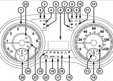
INSTRUMENT CLUSTER DESCRIPTIONS
1. Tachometer The red segments indicate the maximum permissible engine revolutions per minute (RPM x 1000) for each gear range. Before reaching the red area, ease up on the accelerator. 2. Front Fog Light Indicator — If Equipped
This indicator will illuminate when the front fog lights are on.
3. Park/Headlight ON Indicator — If Equipped
This indicator will illuminate when the park lights or headlights are turned on.
4. Turn Signal Indicators
The arrow will flash with the exterior turn signal when the turn signal lever is operated.
UNDERSTANDING YOUR INSTRUMENT PANEL 249
If the vehicle is driven 1 mile (1.6 km) with either turn signal on, a continuous chime will sound to alert you to turn the signal off. If either indicator flashes at a rapid rate, check for a defective outside light bulb. 5. High Beam IndicatorThis indicator shows that the high beam head- lights are on. Push the multifunction lever forward to switch the headlights to high beam, and pull toward yourself (normal position) to return to low beam. 6. Compass Mini-Trip Computer (CMTC) or Electronic Vehicle Information Center (EVIC) Display — If Equipped
Odometer The odometer display shows the total distance the ve- hicle has been driven.
250 UNDERSTANDING YOUR INSTRUMENT PANEL U.S. Federal regulations require that upon transfer of vehicle ownership, the seller certify to the purchaser the correct mileage that the vehicle has been driven. If your odometer needs to be repaired or serviced, the repair technician should leave the odometer reading the same as it was before the repair or service. If s/he cannot do so, then the odometer must be set at zero, and a sticker must be placed in the door jamb stating what the mileage was before the repair or service. It is a good idea for you to make a record of the odometer reading before the repair/ service, so that you can be sure that it is properly reset, or that the door jamb sticker is accurate if the odometer must be reset at zero.
Message Display Area When the appropriate conditions exist, the following odometer messages will display:
door . . . . . . . . . . . . . . . . . . . . . . . . . . . . . Door Ajar gATE . . . . . . . . . . . . . . . . . . . . . . . . . . . Liftgate Ajar LoW tirE. . . . . . . . . . . . . . . . . . . . . Low Tire Pressure gASCAP . . . . . . . . . . . . . . . . . . . . . . . Fuel Cap Fault noFUSE . . . . . . . . . . . . . . . . . . . . . . . . . . Fuse Fault CHAngE OIL . . . . . . . . . . . . . . . Oil Change Required CRUISE. . . . . . . . . . . . . . . . . . . . . Cruise Control On LoCOOL . . . . . . . . . . . . . . . . . . . . . . . . Low Coolant LoWASH . . . . . . . . . . . . . . . . . . . . Low Washer Fluid NOTE: Some of the above warnings will be displayed in the Electronic Vehicle Information Center Display Area located in the instrument cluster. Refer to ”Electronic Vehicle Information Center (EVIC) Display — If Equipped” for further information.
LoW tirE When the appropriate condition exists, the odometer dis- play will toggle between LoW and tirE for three cycles. gASCAP If the vehicle diagnostic system determines that the fuel filler cap is loose, improperly installed, or damaged, a “gASCAP” message will display in the odometer display area. Tighten the fuel filler cap properly and press the TRIP ODOMETER button to turn off the message. If the problem continues, the message will appear the next time the vehicle is started. noFUSE If the vehicle diagnostic system determines that the Ignition Off Draw (IOD) fuse is improperly installed, or damaged, a “noFUSE” message will display in the odom- eter display area. For further information on fuses and fuse locations refer to “Fuses” in “Maintaining Your Vehicle”.
UNDERSTANDING YOUR INSTRUMENT PANEL 251
CHAngE OIL Your vehicle is equipped with an engine oil change indicator system. The CHAngE OIL message will flash in the instrument cluster odometer for approximately 12 seconds, after a single chime has sounded, to indicate the next scheduled oil change interval. The engine oil change indicator system is duty cycle-based, which means the engine oil change interval may fluctuate dependent upon your personal driving style. Unless reset, this message will continue to display each time you turn the ignition switch to the ON/RUN position. To turn off the message temporarily, press and release the Trip / Odometer Display reset button on the instrument cluster. To reset the oil change indicator system (after performing the scheduled maintenance), perform the following steps. 1. Turn the ignition switch to the ON/RUN position (do not start the engine).
252 UNDERSTANDING YOUR INSTRUMENT PANEL 2. Fully depress the accelerator pedal, slowly, three times within 10 seconds. 3. Turn the ignition switch to the OFF/LOCK position. If the indicator message illuminates when you NOTE: start the engine, the oil change indicator system did not reset. If necessary, repeat these steps. Compass Mini-Trip Computer (CMTC) Display — If Equipped On vehicles equipped with Compass Mini-Trip Com- puter (CMTC), the display provides the outside tempera- ture, one of eight compass headings to indicate the direction the vehicle is facing, and the current radio station. For further information, refer to “Compass Mini- Trip Computer”.
Electronic Vehicle Information Center (EVIC) Display — If Equipped The Electronic Vehicle Information Center (EVIC) fea- tures a driver-interactive display that is located in the instrument cluster. For further information, refer to “Electronic Vehicle Information Center (EVIC)”. 7. Anti-Lock Brake (ABS) Light
This light monitors the Anti-Lock Brake System (ABS). The light will turn on when the ignition switch is turned to the ON/RUN position and may stay on for as long as four seconds.
If the ABS light remains on or turns on while driving, it indicates that the Anti-Lock portion of the brake system is not functioning and that service is required. However, the conventional brake system will continue to operate normally if the BRAKE warning light is not on.
If the ABS light is on, the brake system should be serviced as soon as possible to restore the benefits of Anti-Lock brakes. If the ABS light does not turn on when the ignition switch is turned to the ON/RUN position, have the light inspected by an authorized dealer. 8. Tire Pressure Monitoring Telltale Light — If Equipped
Each tire, including the spare (if provided), should be checked monthly when cold and inflated to the inflation pressure recommended by the vehicle manufacturer on the vehicle placard or tire inflation pressure label. (If your vehicle has tires of a different size than the size indicated on the vehicle placard or tire inflation pressure label, you should determine the proper tire inflation pressure for those tires.)
UNDERSTANDING YOUR INSTRUMENT PANEL 253
As an added safety feature, your vehicle has been equipped with a Tire Pressure Monitoring System (TPMS) that illuminates a low tire pressure telltale when one or more of your tires is significantly under-inflated. Accordingly, when the low tire pressure telltale illumi- nates, you should stop and check your tires as soon as possible, and inflate them to the proper pressure. Driving on a significantly under-inflated tire causes the tire to overheat and can lead to tire failure. Under-inflation also reduces fuel efficiency and tire tread life, and may affect the vehicle’s handling and stopping ability. Please note that the TPMS is not a substitute for proper tire maintenance, and it is the driver’s responsibility to maintain correct tire pressure, even if under-inflation has not reached the level to trigger illumination of the TPMS low tire pressure telltale.254 UNDERSTANDING YOUR INSTRUMENT PANEL Your vehicle has also been equipped with a TPMS malfunction indicator to indicate when the system is not operating properly. The TPMS malfunction indicator is combined with the low tire pressure telltale. When the system detects a malfunction, the telltale will flash for approximately one minute and then remain continuously illuminated. This sequence will continue upon subse- quent vehicle start-ups as long as the malfunction exists. When the malfunction indicator is illuminated, the sys- tem may not be able to detect or signal low tire pressure as intended. TPMS malfunctions may occur for a variety of reasons, including the installation of replacement or alternate tires or wheels on the vehicle that prevent the TPMS from functioning properly. Always check the TPMS malfunction telltale after replacing one or more tires or wheels on your vehicle, to ensure that the replacement or alternate tires and wheels allow the TPMS to continue to function properly.
CAUTION!
The TPMS has been optimized for the original equipment tires and wheels. TPMS pressures and warning have been established for the tire size equipped on your vehicle. Undesirable system opera- tion or sensor damage may result when using re- placement equipment that is not of the same size, type, and/or style. Aftermarket wheels can cause sensor damage. Do not use tire sealant from a can or balance beads if your vehicle is equipped with a TPMS, as damage to the sensors may result.
9. Malfunction Indicator Light (MIL)
The Malfunction Indicator Light (MIL) is part of an onboard diagnostic system, called OBD, that monitors engine and automatic transmission con- trol systems. The light will illuminate when the key is in the ON/RUN position, before engine start. If the bulb
does not come on when turning the key from OFF to ON/RUN, have the condition checked promptly. Certain conditions, such as a loose or missing gas cap, poor fuel quality, etc., may illuminate the MIL after engine start. The vehicle should be serviced if the light stays on through several of your typical driving cycles. In most situations, the vehicle will drive normally and will not require towing.
CAUTION!
Prolonged driving with the MIL on could cause damage to the engine control system. It also could affect fuel economy and drivability. If the MIL is flashing, severe catalytic converter damage and power loss will soon occur. Immediate service is required.
UNDERSTANDING YOUR INSTRUMENT PANEL 255
WARNING!
A malfunctioning catalytic converter, as referenced above, can reach higher temperatures than in normal operating conditions. This can cause a fire if you drive slowly or park over flammable substances such as dry plants, wood, cardboard, etc. This could result in death or serious injury to the driver, occupants or others.
10. Electronic Stability Control (ESC) Activation/ Malfunction Indicator Light — If Equipped
The “ESC Activation/Malfunction Indicator Light” in the instrument cluster will come on when the ignition switch is turned to the ON/RUN position. It should go out with the engine running. If the “ESC Activation/Malfunction In- dicator Light” comes on continuously with the engine running, a malfunction has been detected in the ESC
256 UNDERSTANDING YOUR INSTRUMENT PANEL system. If this light remains on after several ignition cycles, and the vehicle has been driven several miles (kilometers) at speeds greater than 30 mph (48 km/h), see your authorized dealer as soon as possible to have the problem diagnosed and corrected. NOTE: • The “ESC Off
Indicator Light” and the “ESC Activation/Malfunction Indicator Light” come on mo- mentarily each time the ignition switch is turned to ON/RUN. • Each time the ignition is turned to ON/RUN, the ESC system will be ON, even if it was turned off previously. • The ESC system will make buzzing or clicking sounds when it is active. This is normal; the sounds will stop when ESC becomes inactive following the maneuver that caused the ESC activation.
11. Electronic Stability Control (ESC) OFF Indicator Light — If Equipped
This light indicates the Electronic Stability Con- trol (ESC) is off.
12. Speedometer Indicates vehicle speed. 13. Fuel Door Reminder
The arrow in this symbol is a reminder that the Fuel Filler Door is located on the left side of the vehicle.
14. Fuel Gauge The pointer shows the level of fuel in the fuel tank when the ignition switch is in the ON/RUN position.
15. Air Bag Warning Light
This light will turn on for four to eight seconds as a bulb check when the ignition switch is first turned to ON/RUN. If the light is either not on during starting, stays on, or turns on while driving, have the system inspected at an authorized dealer as soon as possible. Refer to “Occupant Restraints” in “Things To Know Before Starting Your Vehicle” for further information. 16. Shift Lever Indicator The Shift Lever Indicator is self-contained within the instrument cluster. It displays the gear position of the automatic transmission. NOTE: • You must apply the brakes before shifting from PARK. • The highest available transmission gear is displayed in the lower right corner of the Electronic Vehicle Infor- mation Center (EVIC) whenever the Electronic Range
UNDERSTANDING YOUR INSTRUMENT PANEL 257
Select (ERS) feature is active. Use the +/- selector on the shift lever to activate ERS. Refer to “Automatic Transmission” in “Starting And Operating” for further information.17. Vehicle Security Light — If Equipped
This light will flash at a fast rate for approxi- mately 15 seconds, when the vehicle security alarm is arming, and then will flash slowly until the vehicle is disarmed.
18. Brake Warning Light
This light monitors various brake functions, including brake fluid level and parking brake application. If the brake light turns on it may indicate that the parking brake is applied, that the brake fluid level is low, or that there is a problem with the anti-lock brake system reservoir.
258 UNDERSTANDING YOUR INSTRUMENT PANEL If the light remains on when the parking brake has been disengaged, and the fluid level is at the full mark on the master cylinder reservoir, it indicates a possible brake hydraulic system malfunction or that a problem with the Brake Booster has been detected by the Anti-Lock Brake System (ABS) / Electronic Stability Control (ESC) system. In this case, the light will remain on until the condition has been corrected. If the problem is related to the brake booster, the ABS pump will run when applying the brake and a brake pedal pulsation may be felt during each stop. The dual brake system provides a reserve braking capac- ity in the event of a failure to a portion of the hydraulic system. A leak in either half of the dual brake system is indicated by the Brake Warning Light, which will turn on when the brake fluid level in the master cylinder has dropped below a specified level. The light will remain on until the cause is corrected.
NOTE: The light may flash momentarily during sharp cornering maneuvers, which change fluid level condi- tions. The vehicle should have service performed, and the brake fluid level checked. If brake failure is indicated, immediate repair is neces- sary.
WARNING!
Driving a vehicle with the red brake light on is dangerous. Part of the brake system may have failed. It will take longer to stop the vehicle. You could have a collision. Have the vehicle checked immediately.
Vehicles equipped with the Anti-Lock Brake System (ABS), are also equipped with Electronic Brake Force Distribution (EBD). In the event of an EBD failure, the Brake Warning Light will turn on along with the ABS Light. Immediate repair to the ABS system is required.
Operation of the Brake Warning Light can be checked by turning the ignition switch from the OFF position to the ON/RUN position. The light should illuminate for ap- proximately two seconds. The light should then turn off unless the parking brake is applied or a brake fault is detected. If the light does not illuminate, have the light inspected by an authorized dealer. The light also will turn on when the parking brake is applied with the ignition switch in the ON/RUN posi- tion. NOTE: This light shows only that the parking brake is applied. It does not show the degree of brake application.
UNDERSTANDING YOUR INSTRUMENT PANEL 259
19. Seat Belt Reminder Light
When the ignition switch is first turned to ON/ RUN, this light will turn on for four to eight seconds as a bulb check. During the bulb check, if the driver or front passenger’s seat belt is unbuckled, a chime will sound. After the bulb check or when driving, if the driver’s seat belt remains unbuckled, the Seat Belt Reminder Light will illuminate and the chime will sound. Refer to “Occupant Restraints” in “Things To Know Before Starting Your Vehicle” for further information. 20. Temperature Gauge The temperature gauge shows engine coolant tempera- ture. Any reading within the normal range indicates that the engine cooling system is operating satisfactorily. The gauge pointer will likely indicate a higher tempera- ture when driving in hot weather, up mountain grades, or when towing a trailer. It should not be allowed to exceed the upper limits of the normal operating range.
260 UNDERSTANDING YOUR INSTRUMENT PANEL
CAUTION!
Driving with a hot engine cooling system could damage your vehicle. If the temperature gauge reads “H” pull over and stop the vehicle. Idle the vehicle with the air conditioner turned off until the pointer drops back into the normal range. If the pointer remains on the “H” and you hear continuous chimes, turn the engine off imme- diately and call an authorized dealership for service.
WARNING!
A hot engine cooling system is dangerous. You or others could be badly burned by steam or boiling coolant. You may want to call an authorized dealer- ship for service if your vehicle overheats. If you decide to look under the hood yourself, see “Main- taining Your Vehicle”. Follow the warnings under the Cooling System Pressure Cap paragraph.
21. Low Fuel Light
When the fuel level reaches approximately 2.0 gal (7.8 L) this light will turn on, and remain on until fuel is added.
22. Charging System Light
This light shows the status of the electrical charg- ing system. The light should come on when the ignition switch is first turned to ON/RUN and remain on briefly as a bulb check. If the light stays on or comes on while driving, turn off some of the vehicle’s non-essential electrical devices or increase engine speed (if at idle). If the charging system light remains on, it means that the vehicle is experiencing a problem with the charging system. Obtain SERVICE IMMEDIATELY. See an autho- rized dealer. If jump starting is required, refer to “Jump Starting Procedures” in “What To Do In Emergencies”.
23. Oil Pressure Warning Light
This light indicates low engine oil pressure. The light should turn on momentarily when the engine is started. If the light turns on while driving, stop the vehicle and shut off the engine as soon as possible. A chime will sound for four minutes when this light turns on. Do not operate the vehicle until the cause is corrected. This light does not indicate how much oil is in the engine. The engine oil level must be checked under the hood. 24. Engine Temperature Warning Light
This light warns of an overheated engine condi- tion. As temperatures rise and the gauge ap- proaches H , this indicator will illuminate and a single chime will sound after reaching a set threshold. Further overheating will cause the temperature gauge to
UNDERSTANDING YOUR INSTRUMENT PANEL 261
pass H , the indicator will continuously flash and a continuous chime will occur until the engine is allowed to cool. If the light turns on while driving, safely pull over and stop the vehicle. If the A/C system is on, turn it off. Also, shift the transmission into NEUTRAL and idle the ve- hicle. If the temperature reading does not return to normal, turn the engine off immediately and call for service. Refer to “If Your Engine Overheats” in “What To Do In Emergencies” for further information. 25. Electronic Throttle Control (ETC) LightThis light informs you of a problem with the Electronic Throttle Control (ETC) system. The light will come on when the ignition is first turned to ON/RUN and remain on briefly as a bulb check. If the light does not come on during starting, have the system checked by an authorized dealer.
262 UNDERSTANDING YOUR INSTRUMENT PANEL If a problem is detected, the light will come on while the engine is running. Cycle the ignition key when the vehicle has completely stopped and the shift lever is placed in the PARK position, the light should turn off. If the light remains lit with the engine running, your vehicle will usually be drivable; however, see an autho- rized dealer for service as soon as possible. If the light is flashing when the engine is running, immediate service is required and you may experience reduced performance, an elevated/rough idle or engine stall and your vehicle may require towing.
COMPASS MINI-TRIP COMPUTER (CMTC) — IF EQUIPPED NOTE: • The compass on your vehicle is self-calibrating, elimi- nating the need to manually calibrate the compass.
• If the vehicle is equipped with the manufacturers gps (Navigation Radio), the NAV system will provide the compass direction, and the variance and calibration menus will be unavailable. The compass will perform accurately, based on GPS signals instead of the Earth’s magnetic field.
The Compass Mini-Trip Computer is located in the instrument cluster and features a driver-interactive dis- play (displays information on outside temperature, com- pass direction, and trip information). NOTE: The system will display the last known outside temperature when starting the vehicle and may need to be driven several minutes before the updated tempera- ture is displayed. Engine temperature can also affect the displayed temperature; therefore, temperature readings are not updated when the vehicle is not moving.
CMTC Reset Buttons
CMTC Reset Button Press the STEP button located on the steering wheel to scroll through sub menus (i.e., Trip Functions: AVG Fuel Economy, DTE, Elapsed Time, and Units). To reset the display shown, turn the ignition switch to the ON position, then press and hold the RESET button for approximately two seconds. When the appropriate conditions exist, the following messages will display: NE . . . . . . . Eight-point compass headings are displayed (N, S, E, W, NE, NW, SE, SW) 14°F. . . . . . . . . . . . Temperature (Fahrenheit or Celsius) AVG . . . . . . . . . Average Fuel Economy (U.S. or Metric) DTE . . . . . . . . . . . . . . . . . . . . . . . Distance to Empty ET . . . . . . . . . . . . . . . . . . . . . . . . . . . . Elapsed Time P. . . . . . . . . . . . . . . . . . . . . . . . . . Park Assist On/Off
UNDERSTANDING YOUR INSTRUMENT PANEL 263
Should this wrench symbol display with the letter P next to it, your Park Assist System needs servicing. Contact an authorized dealer.CMTC Trip Odometer (ODO) This display shows the distance traveled since the last reset. Press and release the STEP button on the steering wheel to switch from odometer to Trip A or Trip B or to ECO. Press and hold the RESET button while the odometer/trip odometer is displayed to reset. Trip A Shows the total distance traveled for Trip A since the last reset. Trip B Shows the total distance traveled for Trip B since the last reset.
264 UNDERSTANDING YOUR INSTRUMENT PANEL Compass/Temperature Display
Compass Variance Compass Variance is the difference between Magnetic North and Geographic North. To ensure compass accu- racy, the compass variance should be properly set accord- ing to the variance map for the zone where the vehicle will be driven. When properly set, the compass will automatically account for this difference. NOTE: • A good calibration requires a level surface and an environment free from large metallic objects such as railroad buildings, bridges, underground cables, tracks, etc. • Magnetic and battery powered devices, (such as cell phones, iPod’s, radar detectors, PDA’s and laptops) should be kept away from the top of the instrument panel. This is where the compass module is located
and such devices may interfere and cause false com- pass readings.
Compass Variance Map
To Set The Variance Start the engine and leave the transmission gear selector lever in the PARK position. Press and hold the CMTC reset button (for approximately ten seconds) until the current variance zone number is displayed. To change the zone, press and release the CMTC reset button to increase the variance one step. Repeat as necessary until the desired variance is achieved. NOTE: The factory default zone is 8. During program- ming, the zone value will wrap around from zone 15 to zone 1. Manual Compass Calibration If the compass appears erratic or inaccurate, and the variance has been properly set, you may wish to manu- ally recalibrate the compass. To manually calibrate the compass: 1. Start the engine and leave the transmission in the PARK position.
UNDERSTANDING YOUR INSTRUMENT PANEL 265
2. Press and hold the RESET button (for approximately 10 seconds) until the current variance zone number is displayed. 3. Release the RESET button, then press and hold again for approximately 10 seconds, until the direction is displayed, with the CAL indicator on continuously in the display. 4. To complete the compass calibration, drive the vehicle in one or more complete 360–degree circles, under 5 mph (8 km/h) in an area free from power lines and large metallic objects, until the CAL indicator turns off. The compass will now function normally.ELECTRONIC VEHICLE INFORMATION CENTER (EVIC) — IF EQUIPPED The Electronic Vehicle Information Center (EVIC) fea- tures a driver-interactive display that is located in the instrument cluster.
266 UNDERSTANDING YOUR INSTRUMENT PANEL
Electronic Vehicle Information Center (EVIC)
This system conveniently allows the driver to select a variety of useful information by pressing the switches mounted on the steering wheel. The EVIC consists of the following: • Radio Information
• Fuel Economy • Vehicle Speed • Trip Info • Tire PSI • Vehicle Info • Messages • Units • System Setup (Personal Settings) • Turn Menu Off
The system allows the driver to select information by pressing the following buttons mounted on the steering wheel:
EVIC Steering Wheel Buttons
UNDERSTANDING YOUR INSTRUMENT PANEL 267
UP Button
Press and release the UP button to scroll up- ward through the main menus (Fuel Economy, Vehicle Info, Tire PSI, Cruise, Messages, Units, System Setup) and sub-menus.
DOWN Button
Press and release the DOWN button to scroll downward through the main menus and sub- menus.
SELECT Button
The SELECT button allows access to informa- tion in EVIC submenus, selects some feature settings, and resets some EVIC features. The EVIC prompts the driver when the SELECT button can be used by displaying the right arrow graphic.
268 UNDERSTANDING YOUR INSTRUMENT PANEL BACK Button
Press the BACK button to scroll back to a previous menu or sub-menu.
Electronic Vehicle Information Center (EVIC) Displays When the appropriate conditions exist, the EVIC displays the following messages: • Key in ignition • Ignition or Accessory On • Remote start aborted — Door ajar • Remote start aborted — Hood ajar • Remote start aborted — L/Gate ajar • Remote start aborted — Fuel low • Remote start disabled — Start Vehicle to Reset
• Remote start active — Push Start Button • Remote start active — Key to Run • Wrong Key • Damaged Key • Key not programmed • Vehicle Not in Park • Key Left Vehicle • Key Not Detected • Press Brake Pedal and Push Button to Start • Door(s) Ajar (with a single chime, if vehicle is in • Liftgate Ajar (chime will sound when vehicle starts • Low Tire Pressure
moving)
motion)
Passive Entry - if equipped)
ing System” in “Starting And Operating”)
• Service TPM System (refer to “Tire Pressure Monitor- • Premium TPM Service Graphic Display • Turn Signal On • RKE Battery Low • Service Keyless System (refer to Keyless Enter-N-Go, • LOW WASHER FLUID • Oil Change Required • Left Front Turn Signal Light Out • Left Rear Turn Signal Light Out • Right Front Turn Signal Light Out • Right Rear Turn Signal Light Out • Park Assist Disabled
UNDERSTANDING YOUR INSTRUMENT PANEL 269
• Service Park Assist System • Personal Settings Not Available — Vehicle Not In Park • Blind Spot System Off — This message is displayed when the ignition is turned to ON to indicate the Blind Spot System has been turned off. • Blind Spot System Not Available — This message is displayed to indicate the Blind Spot Monitor (BSM) system is temporarily unavailable due to sensor block- age, electronic interference, or other ⬙temporary⬙ con- ditions. When this message is displayed both outside rear view icons will be illuminated. If electronic inter- ference is present, the BSM system will illuminate the icon only on the side of interference as long as interference is present. • Service Blind Spot System — This message is dis- played to indicate the Blind Spot Monitor (BSM) system is permanently unavailable. The driver will
270 UNDERSTANDING YOUR INSTRUMENT PANEL
receive an EVIC message and the BSM display warn- ing in both mirrors will be permanently illuminated. If this message is present see an authorized dealer.
EVIC White Telltale Lights This area will show reconfigurable white caution tell- tales. These telltales include: • Electronic Range Select (ERS) Status The shift lever status “5,4,3,2,1” are displayed indicating the shift lever position. Telltales “5,4,3,2,1” indicate the Electronic Range Select (ERS) feature has been engaged and the gear selected is displayed. For further informa- tion on ERS, refer to “Starting And Operating” • Electronic Speed Control Ready
This light will turn on when the electronic speed control is ready. For further information, refer to “Electronic Speed Control” in “Under- standing The Features Of Your Vehicle.”
• Electronic Speed Control SET
This light will turn on when the electronic speed control is SET. For further information, refer to “Electronic Speed Control” in “Under- standing The Features Of Your Vehicle.”
EVIC Amber Telltale Lights This area will show reconfigurable amber caution tell- tales. These telltales include: • Low Fuel Light
When the fuel level reaches approximately 3.0 gal (11.0 L) this light will turn on, and remain on until fuel is added.
• Loose Gascap Indicator
If the vehicle diagnostic system determines that the fuel filler cap is loose, improperly installed, or damaged, a loose gascap indicator will display in the telltale display area. Tighten the fuel filler cap properly and press the SELECT button
to turn off the message. If the problem continues, the message will appear the next time the vehicle is started. A loose, improperly installed, or damaged fuel filler cap may also turn on the Malfunction Indicator Light (MIL). • Windshield Washer Fluid Low Indicator
This light will turn on to indicate the wind- shield washer fluid is low.
EVIC Red Telltale Lights This area will show reconfigurable red telltales. These telltales include: • Door Ajar
This light will turn on to indicate that one or more doors may be ajar.
UNDERSTANDING YOUR INSTRUMENT PANEL 271
• Oil Pressure Warning Light
This light indicates low engine oil pressure. The light should turn on momentarily when the engine is started. If the light turns on while driving, stop the vehicle and shut off the engine as soon as possible. A chime will sound for four minutes when this light turns on. Do not operate the vehicle until the cause is corrected. This light does not show how much oil is in the engine. The engine oil level must be checked under the hood. • Charging System Light
This light shows the status of the electrical charg- ing system. The light should come on when the ignition switch is first turned ON and remain on briefly as a bulb check. If the light stays on or comes on while driving, turn off some of the vehicle’s non-essential electrical devices or increase engine speed (if at idle). If the charging system light remains on, it means that the
272 UNDERSTANDING YOUR INSTRUMENT PANEL vehicle is experiencing a problem with the charging system. Obtain SERVICE IMMEDIATELY. See an autho- rized dealer. If jump starting is required, refer to “Jump Starting Procedures” in “What To Do In Emergencies”. • Electronic Throttle Control (ETC) Light
This light informs you of a problem with the Electronic Throttle Control (ETC) system. The light will come on when the ignition is first turned ON and remain on briefly as a bulb check. If the light does not come on during starting, have the system checked by an authorized dealer. If a problem is detected, the light will come on while the engine is running. Cycle the ignition key when the vehicle has completely stopped and the shift lever is placed in the PARK position. The light should turn off.
If the light remains lit with the engine running, your vehicle will usually be drivable. However, see an autho- rized dealer for service as soon as possible. If the light is flashing when the engine is running, immediate service is required. You may experience reduced performance, an elevated/rough idle or engine stall and your vehicle may require towing. • Engine Temperature Warning Light
This light warns of an overheated engine condi- tion. As temperatures rise and the gauge ap- proaches H, this indicator will illuminate and a single chime will sound after reaching a set threshold. Further overheating will cause the temperature gauge to pass H, the indicator will continuously flash and a continuous chime will occur until the engine is allowed to cool. If the light turns on while driving, safely pull over and stop the vehicle. If the A/C system is on, turn it off. Also,
shift the transmission into NEUTRAL and idle the ve- hicle. If the temperature reading does not return to normal, turn the engine off immediately and call for service. Refer to “If Your Engine Overheats” in “What To Do In Emergencies” for more information. • Transmission Temperature Warning Light
This light indicates that the transmission fluid temperature is running hot. This may occur with severe usage, such as trailer towing. If this light turns on, safely pull over and stop the vehicle. Then, shift the transmission into NEUTRAL and run the engine at idle or faster until the light turns off.
CAUTION!
Continuous driving with the Transmission Tempera- ture Warning Light illuminated will eventually cause severe transmission damage or transmission failure.
UNDERSTANDING YOUR INSTRUMENT PANEL 273
WARNING!
If the Transmission Temperature Warning Light is illuminated and you continue operating the vehicle, in some circumstances you could cause the fluid to boil over, come in contact with hot engine or exhaust components and cause a fire.
Oil Change Required Your vehicle is equipped with an engine oil change indicator system. The Oil Change Required message will flash in the EVIC display for approximately 10 seconds, after a single chime has sounded, to indicate the next scheduled oil change interval. The engine oil change indicator system is duty-cycle based, which means the engine oil change interval may fluctuate dependent upon your personal driving style.
274 UNDERSTANDING YOUR INSTRUMENT PANEL Unless reset, this message will continue to display each time you turn the ignition switch to the ON/RUN position. To turn off the message temporarily, press and release the Menu button. To reset the oil change indicator system (after performing the scheduled maintenance), perform the following steps. 1. Turn the ignition switch to the ON position (do not start the engine.) 2. Fully depress the accelerator pedal, slowly, three times within 10 seconds. 3. Turn the ignition switch to the OFF/LOCK position. If the indicator message illuminates when you NOTE: start the engine, the oil change indicator system did not reset. If necessary, repeat these steps.
Fuel Economy Press and release the UP or DOWN button until “Fuel Economy” displays highlighted in the EVIC and press the SELECT button. The following Fuel Economy func- tions display in the EVIC: • Average Fuel Economy • Distance To Empty (DTE) • Miles Per Gallon (MPG) Average Fuel Economy Shows the average fuel economy since the last reset. The Average Fuel Economy can be reset by following the prompt in the EVIC to use the SELECT button. When the fuel economy is reset, the display will read “zero” for two seconds. Then, the history information will be erased, and the averaging will continue from the last fuel aver- age reading before the reset.
UNDERSTANDING YOUR INSTRUMENT PANEL 275
NOTE: Significant changes in driving style or vehicle loading will greatly affect the actual drivable distance of the vehicle, regardless of the DTE displayed value. When the DTE value is less than 30 miles (48 km) estimated driving distance, the DTE display will change to a “LOW FUEL” message. This display will continue until the vehicle runs out of fuel. Adding a significant amount of fuel to the vehicle will turn off the “LOW FUEL” message and a new DTE value will display. Vehicle Speed Press and release the UP or DOWN button until “Vehicle Speed” displays highlighted in the EVIC and press the SELECT button. Press the SELECT button to display the current speed in mph or km/h. Pressing the SELECT button a second time will toggle the unit of measure between mph or km/h.Average Fuel Economy Display
Distance To Empty (DTE) Shows the estimated distance that can be traveled with the fuel remaining in the tank. This estimated distance is determined by a weighted average of the instantaneous and average fuel economy, according to the current fuel tank level. DTE cannot be reset through the SELECT button.
276 UNDERSTANDING YOUR INSTRUMENT PANEL NOTE: Changing the unit of measure in the Vehicle Speed menu will not change the unit of measure in the EVIC. Trip Info Press and release the UP or DOWN button until “Trip Info” is highlighted in the EVIC and press the SELECT button. Press and release the UP/DOWN buttons to highlight one of the following functions if you want to reset it: Trip A Shows the total distance traveled for Trip A since the last reset. Trip B Shows the total distance traveled for Trip B since the last reset.
Elapsed Time Shows the total elapsed time of travel since the last reset when the ignition switch is in the ACC position. Elapsed time will increment when the ignition switch is in the ON or START position. To Reset A Trip Function Reset will only occur while a resettable function is selected (highlighted). Press and hold the SELECT button to clear the resettable function being displayed. Units Press and release the UP or DOWN button until “Units” displays highlighted in the EVIC and press the SELECT button. The EVIC, odometer, and navigation system (if equipped) can be changed between English and Metric units of measure. To make your selection, scroll up or down until the preferred setting is highlighted, then press and release the SELECT button until a check-mark appears next to the setting, showing that the setting has been selected.
Vehicle Info (Customer Information Features) Press and release the UP or DOWN button until “Vehicle Info” displays in the EVIC and press the SELECT button. Press the UP and DOWN button to scroll through the selections below: • Coolant Temp Displays the actual coolant temperature. • Oil Temperature Displays the actual oil temperature. • Oil Pressure Displays the actual oil pressure. • Engine Hours Displays the number of hours of engine operation. Compass / Temperature Display The compass readings indicate the direction the vehicle is facing. The EVIC will display one of eight compass readings and the outside temperature.
UNDERSTANDING YOUR INSTRUMENT PANEL 277
NOTE: The system will display the last known outside temperature when starting the vehicle and may need to be driven several minutes before the updated tempera- ture is displayed. Engine temperature can also affect the displayed temperature; therefore, temperature readings are not updated when the vehicle is not moving. Automatic Compass Calibration This compass is self-calibrating, which eliminates the need to manually reset the compass. When the vehicle is new, the compass may appear erratic and the EVIC will display CAL until the compass is calibrated. You may also calibrate the compass by completing one or more 360–degree turns (in an area free from large metal or metallic objects) until the CAL indicator displayed in the EVIC turns off. The compass will now function normally.278 UNDERSTANDING YOUR INSTRUMENT PANEL NOTE: A good calibration requires a level surface and an environment free from large metallic objects such as buildings, bridges, underground cables, railroad tracks, etc. Manual Compass Calibration If the compass appears erratic and the CAL indicator does not appear in the EVIC display, you must put the compass into the Calibration Mode manually, as follows: 1. Turn ON the ignition switch. 2. Press the UP or DOWN button until the Setup (Customer-Programmable Features) menu is reached, then press the SELECT button. 3. Press the DOWN button until “Calibrate Compass” is displayed in the EVIC. 4. Press and release the SELECT button to start the calibration. The “CAL” indicator will be displayed in the EVIC.
5. Complete one or more 360–degree turns (in an area free from large metal or metallic objects) until the “CAL” indicator turns off. The compass will now function normally. Compass Variance Compass Variance is the difference between Magnetic North and Geographic North. To compensate for the differences the variance should be set for the zone where the vehicle is driven, per the zone map. Once properly set, the compass will automatically compensate for the differences, and provide the most accurate compass heading. For the most accurate compass performance, the compass must be set using the following steps. NOTE: Keep magnetic materials away from the top of the instrument panel, such as iPod’s, Mobile Phones, Laptops and Radar Detectors. This is where the compass module is located, and it can cause interference with the compass sensor, and it may give false readings.
UNDERSTANDING YOUR INSTRUMENT PANEL 279
3. Press the DOWN button until the “Compass Variance” message is displayed in the EVIC, then press the SELECT button. The last variance zone number displays in the EVIC. 4. Press and release the SELECT button until the proper variance zone is selected, according to the map. 5. Press and release the RETURN button to exit. Customer-Programmable Features (System Setup) Personal Settings allows you to set and recall features when the transmission is in PARK. If the transmission is out of PARK or the vehicle begins moving, a warning message SYSTEM SETUP NOT AVAILABLE VEHICLE NOT IN PARK displays when you try to select “System Setup” from the main menu. Press and release the UP or DOWN button until ⬙System Setup⬙ is highlighted in the main menu of the EVIC. ThenCompass Variance Map
1. Turn the ignition switch ON. 2. Press the UP or DOWN button until the Setup (Customer-Programmable Features) menu is reached, then press the SELECT button.
280 UNDERSTANDING YOUR INSTRUMENT PANEL press the SELECT button to enter the System Setup sub-menu. Press and release the UP or DOWN button to select a feature form the following choices: Language When in this display you may select one of five lan- guages for all display nomenclature, including the trip functions and the navigation system (if equipped). Press the UP or DOWN button while in this display and scroll through the language choices. Press the SELECT button to select English, Spanish (Español), French (Français). Then, as you continue, the information will display in the selected language. Enable/Disable the Rear Park Assist System The Rear Park Assist system will scan for objects behind the vehicle when the transmission is in the REVERSE position and the vehicle speed is less than 11 mph (18 km/h). The system can be enabled with Sound Only, Sound and Display, or turned OFF through the EVIC. To
make your selection, press and release the SELECT button until a check-mark appears next to the feature showing the system has been activated or the check-mark is removed showing the system has been deactivated. Refer to “Rear Park Assist System” in “Understanding The Features Of Your Vehicle” for system function and operating information. Auto Unlock Doors Exit When ON is selected, all doors will unlock when the vehicle is stopped and the transmission is in the PARK or NEUTRAL position and the driver’s door is opened. To make your selection, press and release the SELECT button until a check-mark appears next to the feature showing the system has been activated or the check-mark is removed showing the system has been deactivated. Remote Unlock Sequence When Driver Door 1st Press is selected, only the driver’s door will unlock on the first press of the Remote Keyless
Entry (RKE) transmitter UNLOCK button. When Driver Door 1st Press is selected, you must press the RKE transmitter UNLOCK button twice, to unlock the passen- ger’s doors. When All Doors 1st Press is selected, all of the doors will unlock on the first press of the RKE transmitter UNLOCK button. To make your selection, press and release the SELECT button until a check-mark appears next to the feature showing the system has been activated or the check-mark is removed showing the system has been deactivated. RKE Linked To Memory When this feature is selected the memory seat, mirror, and radio settings will return to the memory set position when the RKE transmitter UNLOCK button is pressed. If this feature is not selected then the memory seat, mirror, and radio settings can only return to the memory set position using the door mounted switch. To make your selection, press and release the SELECT button until a check-mark appears next to the feature showing the
UNDERSTANDING YOUR INSTRUMENT PANEL 281
system has been activated or the check-mark is removed showing the system has been deactivated. Horn With Remote Lock When this feature is selected, a short horn sound will occur when the RKE transmitter LOCK button is pressed. This feature may be selected with or without the Flash Lamps with Lock feature. To make your selection, press and release the SELECT button until a check-mark ap- pears next to the feature showing the system has been activated or the check-mark is removed showing the system has been deactivated. Flash Lamps with Lock When ON is selected, the front and rear turn signals will flash when the doors are locked or unlocked with the RKE transmitter. This feature may be selected with or without the sound horn on lock feature selected. To make your selection, press and release the SELECT button until a check-mark appears next to the feature showing the282 UNDERSTANDING YOUR INSTRUMENT PANEL system has been activated or the check-mark is removed showing the system has been deactivated. Headlamp Off Delay When this feature is selected, the driver can choose to have the headlights remain on for 0, 30, 60, or 90 seconds when exiting the vehicle. To make your selection, scroll up or down until the preferred setting is highlighted, then press and release the SELECT button until a check- mark appears next to the setting, showing that the setting has been selected. Headlamps with Wipers (Available with Auto Headlights Only) When ON is selected, and the headlight switch is in the AUTO position, the headlights will turn on approxi- mately 10 seconds after the wipers are turned on. The headlights will also turn off when the wipers are turned off if they were turned on by this feature. To make your
selection, press and release the SELECT button until a check-mark appears next to the setting, showing that the setting has been selected. NOTE: Turning the headlights on during the daytime causes the instrument panel lights to dim. To increase the brightness, refer to “Lights” in “Understanding The Features Of Your Vehicle.” Intermittent Wiper Options — If Equipped When ON is selected, the system will automatically activate the windshield wipers if it senses moisture on the windshield. To make your selection, press and release the SELECT button until a check-mark appears next to the feature showing the system has been activated or the check-mark is removed showing the system has been deactivated. When the system is deactivated, the system reverts to the standard intermittent wiper operation.
Key-Off Power Delay When this feature is selected, the power window switches, radio, Uconnect™ phone (if equipped), DVD video system (if equipped), power sunroof (if equipped), and power outlets will remain active for up to 10 minutes after the ignition switch is turned OFF. Opening either front vehicle door will cancel this feature. To make your selection, scroll up or down until the preferred setting is highlighted, then press and release the SELECT button until a check-mark appears next to the setting, showing that the setting has been selected. Illuminated Approach When this feature is selected, the headlights will activate and remain on for up to 90 seconds when the doors are unlocked with the RKE transmitter. To make your selec- tion, scroll up or down until the preferred setting is highlighted, then press and release the SELECT button until a check-mark appears next to the setting, showing that the setting has been selected.
UNDERSTANDING YOUR INSTRUMENT PANEL 283
Flashers with Sliding Door When this feature is selected the signal lamps activate when power or manual sliding doors are in operation, signaling other drivers that someone may be exiting or entering the vehicle. To make your selection, press and release the SELECT button until a check-mark appears next to the feature showing the system has been activated or the check-mark is removed showing the system has been deactivated. Keyless Enter-N-Go (Passive Entry) — If Equipped The Passive Entry system is an enhancement to the vehicle’s Remote Keyless Entry (RKE) system. When ON is selected, this feature allows you to lock and unlock the vehicle’s door(s) without having to press the RKE trans- mitter lock or unlock buttons. To make your selection, press and release the RESET button until “ON” or “OFF” appears. Refer to “Keyless Enter-N-Go — If Equipped” in “Things To Know Before Starting Your Vehicle” for further information.
284 UNDERSTANDING YOUR INSTRUMENT PANEL Easy Entry/Exit Seat This feature provides automatic driver seat positioning to enhance driver mobility when entering and exiting the vehicle. To make your selection, press and release the SELECT button until a check-mark appears next to the feature showing the system has been activated or the check-mark is removed showing the system has been deactivated. NOTE: The seat will return to the memorized seat location (if Recall Memory with Remote Key Unlock is set to ON) when the RKE transmitter is used to unlock the door. Refer to “Driver Memory Seat” in “Understanding The Features Of Your Vehicle” for further information. Tilt Mirror In Reverse When this feature is selected and the vehicle is placed in a reverse gear, the driver’s side mirror will tilt downward to allow the driver to see into the previous blind spot and avoid objects in close proximity to the rear of the vehicle.
To make your selection, press and release the SELECT button until a check-mark appears next to the feature showing the system has been activated or the check-mark is removed showing the system has been deactivated. Blind Spot Alert There are three selections when operating Blind Spot Alert (“Blind Spot Alert Lights”, “Blind Spot Alert Lights/CHM”, “Blind Spot Alert Off”). The Blind Spot Alert feature can be activated in “Blind Spot Alert Lights” mode, when this mode is selected the Blind Spot Monitor (BSM) system is activated and will only show a visual alert in the outside mirrors. The Blind Spot Alert feature can be activated in “Blind Spot Alert Lights/CHM” mode, in this mode the Blind Spot Monitor (BSM) will show a visual alert in the outside mirrors as well as an audible alert when the turn signal is on. When “Blind Spot Alert Off” is selected the Blind Spot Monitor (BSM) system is deactivated.
To make your selection, press and release the SELECT button until a check-mark appears next to the feature showing the system has been activated or the check-mark is removed showing the system has been deactivated. If your vehicle has experienced any damage in NOTE: the area where the sensor is located, even if the fascia is not damaged, the sensor may have become misaligned. Take your vehicle to an authorized dealer to verify sensor alignment. Having a sensor that is misaligned will result in the BSM not operating to specification. Calibrate Compass Refer to “Compass Display” for more information. Compass Variance Refer to “Compass Display” for more information.
UNDERSTANDING YOUR INSTRUMENT PANEL 285
MEDIA CENTER 730N/430/430N (RHR/RER/RBZ/ RHB) CD/DVD/HDD/NAV — IF EQUIPPED
NOTE: The sales code is located on the lower right side of the unit’s faceplate. Refer to your Uconnect™ Multimedia RHR, RER, RBZ or RHB user’s manual for detailed operating instructions. Operating Instructions (Voice Command System) — If Equipped Refer to “Voice Command” in the Uconnect™ User Manual located on the DVD for further details. Operating Instructions (Uconnect™ Phone) — If Equipped Refer to “Uconnect™ Phone” in the Uconnect™ User Manual located on the DVD for further details.
286 UNDERSTANDING YOUR INSTRUMENT PANEL MEDIA CENTER 130 (SALES CODE RES)
NOTE: The radio sales code is located on the lower right side of the radio faceplate.
Media Center 130 (RES)
Operating Instructions — Radio Mode
NOTE: The ignition switch must be in the ON or ACC position to operate the radio. Power Switch/Volume Control (Rotary) Push the ON/VOLUME control knob to turn on the radio. Push the ON/VOLUME control knob a second time to turn off the radio. Electronic Volume Control The electronic volume control turns continuously (360
degrees) in either direction, without stopping. Turning the ON/VOLUME control knob to the right increases the volume, and to the left decreases it. When the audio system is turned on, the sound will be set at the same volume level as last played.SEEK Buttons Press and release the SEEK buttons to search for the next listenable station in AM/FM mode. Press the right switch to seek up and the left switch to seek down. The radio will remain tuned to the new station until you make another selection. Holding either button will bypass stations without stopping, until you release it. TIME Button Press the TIME button to alternate display of the time and radio frequency. Clock Setting Procedure 1. Press and hold the TIME button until the hours blink. 2. Adjust the hours by turning the right side TUNE/ SCROLL control knob. 3. After adjusting the hours, press the right side TUNE/ SCROLL control knob to set the minutes. The minutes will begin to blink.
UNDERSTANDING YOUR INSTRUMENT PANEL 287
the minutes using the right side TUNE/ 4. Adjust SCROLL control knob. Press the TUNE/SCROLL control knob to save time change. 5. To exit, press any button/knob, or wait five seconds. RW/FF Pressing the RW (Rewind) or FF (Fast Forward) buttons causes the tuner to search for the next frequency in the direction of the arrows. This feature operates in either AM or FM frequencies. TUNE Control Turn the rotary TUNE/SCROLL control knob clockwise to increase or counterclockwise to decrease the frequency. Setting the Tone, Balance, and Fade Push the rotary TUNE/SCROLL control knob and BASS will display. Turn the TUNE/SCROLL control knob to the right or left to increase or decrease the bass tones.288 UNDERSTANDING YOUR INSTRUMENT PANEL Push the rotary TUNE/SCROLL control knob a second time and MID will display. Turn the TUNE/SCROLL control knob to the right or left to increase or decrease the mid-range tones. Push the rotary TUNE/SCROLL control knob a third time and TREBLE will display. Turn the TUNE/SCROLL control knob to the right or left to increase or decrease the treble tones. Push the rotary TUNE/SCROLL control knob a fourth time and BALANCE will display. Turn the TUNE/ SCROLL control knob to the right or left to adjust the sound level from the right or left side speakers. Push the rotary TUNE/SCROLL control knob a fifth time and FADE will display. Turn the TUNE/SCROLL control knob to the left or right to adjust the sound level between the front and rear speakers.
Push the rotary TUNE/SCROLL control knob again to exit setting tone, balance, and fade. AM/FM Button Press the buttons to select either AM or FM mode. SET/RND Button — To Set the Pushbutton Memory When you are receiving a station that you wish to commit to pushbutton memory, press the SET/RND button. The symbol SET 1 will now show in the display window. Select the button (1 to 6) you wish to lock onto this station and press and release that button. If a button is not selected within five seconds after pressing the SET/RND button, the station will continue to play but will not be stored into pushbutton memory.
You may add a second station to each pushbutton by repeating the above procedure with this exception: Press the SET/RND button twice and SET 2 will show in the display window. Each button can be set for SET 1 and SET 2 in both AM and FM. This allows a total of 12 AM and 12 FM stations to be stored into pushbutton memory. The stations stored in SET 2 memory can be selected by pressing the pushbutton twice. Every time a preset button is used, a corresponding button number will display. Buttons 1 - 6
These buttons tune the radio to the stations that you commit to pushbutton memory (12 AM and 12 FM stations). DISC Button Pressing the DISC button will allow you to switch from AM/FM modes to Disc modes.UNDERSTANDING YOUR INSTRUMENT PANEL 289
Operation Instructions — CD MODE For CD And MP3 Audio Play NOTE: • The ignition switch must be in the ON or ACC • This radio is capable of playing compact discs (CD), recordable compact discs (CD-R), rewritable compact discs (CD-RW), compact discs with MP3 tracks and multisession compact discs with CD and MP3 tracks.
position to operate the radio.
Inserting Compact Disc(s) Gently insert one CD into the CD player with the CD label facing up. The CD will automatically be pulled into the CD player and the CD icon will illuminate on the radio display. If a CD does not go into the slot more than 1.0 in (2.5 cm), a disc may already be loaded and must be ejected before a new disc can be loaded.
290 UNDERSTANDING YOUR INSTRUMENT PANEL If you insert a disc with the ignition ON and the radio ON, the unit will switch from radio to CD mode and begin to play when you insert the disc. The display will show the track number, and index time in minutes and seconds. Play will begin at the start of track 1.
CAUTION!
away and jam the player mechanism.
• This CD player will accept 4-3/4 in (12 cm) discs only. The use of other sized discs may damage the CD player mechanism. • Do not use adhesive labels. These labels can peel • The RES Media Center is a single CD player. Do not attempt to insert a second CD if one is already loaded. • Dual-media disc types (one side is a DVD, the other side is a CD) should not be used, and they can cause damage to the player.
EJECT Button - Ejecting a CD
Press the EJECT button to eject the CD.
If you have ejected a disc and have not removed it within 10 seconds, it will be reloaded. If the CD is not removed, the radio will reinsert the CD but will not play it. A disc can be ejected with the radio and ignition OFF. NOTE: Ejecting with the ignition OFF is not allowed on convertible or soft-top models (if equipped). SEEK Button Press the right SEEK button for the next selection on the CD. Press the left SEEK button to return to the beginning of the current selection, or return to the beginning of the previous selection if the CD is within the first second of the current selection. Pressing and holding the SEEK button will allow faster scrolling through the tracks in CD and MP3 modes.
TIME Button Press this button to change the display from a large CD playing time display to a small CD playing time display. RW/FF Press and hold the FF (Fast Forward) button and the CD player will begin to fast forward until FF is released, or RW or another CD button is pressed. The RW (Reverse) button works in a similar manner. AM/FM Button Press the button to select either AM or FM mode. SET/RND Button (Random Play Button) Press this button while the CD is playing to activate Random Play. This feature plays the selections on the compact disc in random order to provide an interesting change of pace. Press the right SEEK button to move to the next ran- domly selected track.
UNDERSTANDING YOUR INSTRUMENT PANEL 291
Press the RND button a second time to stop Random Play. Notes on Playing MP3 Files The radio can play MP3 files; however, acceptable MP3
file recording media and formats are limited. When writing MP3 files, pay attention to the following restric- tions. Supported Media (Disc Types) The MP3 file recording media supported by the radio are CDDA, CD-R, CD-RW, MP3, and CDDA+MP3. Supported Medium Formats (File Systems) The medium formats supported by the radio are ISO 9660
Level 1 and Level 2 and includes the Joliet extension. When reading discs recorded using formats other than ISO 9660 Level 1 and Level 2, the radio may fail to read files properly and may be unable to play the file nor- mally. UDF and Apple HFS formats are not supported.292 UNDERSTANDING YOUR INSTRUMENT PANEL The radio uses the following limits for file systems: • Maximum number of folder levels: 8
• Maximum number of files: 255
• Maximum number of folders. (The radio display of file names and folder names is limited. For large numbers of files and/or folders, the radio may be unable to display the file name and folder name, and will assign a number instead. With a maximum number of files, exceeding 20 folders will result in this display. With in this 200 files, exceeding 50 folders will result display.) • Maximum number of characters in file/folder names: • Level 1: 12 (including a separator ⬙.⬙ and a three- • Level 2: 31 (including a separator ⬙.⬙ and a three-character extension)
character extension)
Multisession disc formats are supported by the radio. Multisession discs may contain combinations of normal CD audio tracks and computer files (including MP3 files). Discs created with an option such as ⬙keep disc open after writing⬙ are most likely multisession discs. The use of multisession for CD audio or MP3 playback may result in longer disc loading times. Supported MP3 File Formats The radio will recognize only files with the *.MP3 exten- sion as MP3 files. Non-MP3 files named with the *.MP3
extension may cause playback problems. The radio is designed to recognize the file as an invalid MP3 and will not play the file. When using the MP3 encoder to compress audio data to an MP3 file, the bit rate and sampling frequencies in the following table are supported. In addition, variable bitrates (VBR) are also supported. The majority of MP3 files use a 44.1 kHz sampling rate and a 192, 160, 128, 96 or VBR bit rate. MPEG
Sampling
Specification
MPEG-1 Audio
Layer 3
MPEG-2 Audio
Layer 3
48, 44.1, 32
Frequency (kHz) Bit Rate (kbps) 320, 256, 224, 192, 160, 128, 112, 96, 80, 64, 56, 48, 40, 32
160, 128, 144, 112, 96, 80, 64, 56, 48, 40, 32, 24,24, 22.05, 16
16, 8
ID3 Tag information for artist, song title, and album title are supported for version 1 ID3 tags. ID3 version 2 is not supported by the radios. Playlist files are not supported. MP3 Pro files are not supported.
UNDERSTANDING YOUR INSTRUMENT PANEL 293
Playback of MP3 Files When a medium containing MP3 data is loaded, the radio checks all files on the medium. If the medium contains a lot of folders or files, the radio will take more time to start playing the MP3 files. Loading times for playback of MP3 files may be affected by the following: • Media - CD-RW media may take longer to load than • Medium formats - Multisession discs may take longer • Number of files and folders - Loading times will
to load than non-multisession discs
CD-R media
increase with more files and folders
To increase the speed of disc loading, it is recommended to use CD-R media and single-session discs. To create a single-session disc, enable the “Disc at Once” option before writing to the disc.
294 UNDERSTANDING YOUR INSTRUMENT PANEL Operation Instructions - Auxiliary Mode The auxiliary (AUX) jack is an audio input jack, which allows the user to plug in a portable device, such as an MP3 player, or cassette player, and utilize the vehicle’s audio system to amplify the source and play through the vehicle speakers. Pressing the DISC/AUX button will change the mode to auxiliary device if the AUX jack is connected. NOTE: The AUX device must be turned on and the device’s volume set to proper level. If the AUX audio is not loud enough, turn the device’s volume up. If the AUX audio sounds distorted, turn the device’s volume down. TIME Button (Auxiliary Mode) Press this button to change the display to time of day. The time of day will display for five seconds (when ignition is OFF).
MEDIA CENTER 130 WITH SATELLITE RADIO (SALES CODE RES+RSC)
NOTE: The radio sales code is located on the lower right side of the radio faceplate.
Media Center 130 (RES/RSC)
Operating Instructions — Radio Mode
NOTE: The ignition switch must be in the ON/RUN or ACC position to operate the radio. Power Switch/Volume Control (Rotary) Push the ON/VOLUME control knob to turn on the radio. Push the ON/VOLUME control knob a second time to turn off the radio. Electronic Volume Control The electronic volume control turns continuously (360
degrees) in either direction without stopping. Turning the ON/VOLUME control knob to the right increases the volume and to the left decreases it. When the audio system is turned on, the sound will be set at the same volume level as last played. SEEK Buttons Press and release the SEEK buttons to search for the next listenable station in AM/FM mode. Press the right switchUNDERSTANDING YOUR INSTRUMENT PANEL 295
to seek up and the left switch to seek down. The radio will remain tuned to the new station until you make another selection. Holding either button will bypass stations without stopping until you release it. Voice Command System (Radio) — If Equipped Refer to “Voice Command” in the Uconnect™ User Manual located on the DVD for further details. Voice Command Button Uconnect™ Phone — If Equipped Press this button to operate the Uconnect™ Phone feature (if equipped). Refer to “Voice Command” in the Uconnect™ User Manual located on the DVD for further details. If your vehicle is not equipped with or this feature is not available on your vehicle, a “Not Equipped With Uconnect Phone” message will display on the radio screen.296 UNDERSTANDING YOUR INSTRUMENT PANEL Phone Button Uconnect™ Phone — If Equipped Press this button to operate the Uconnect™ Phone feature (if equipped). Refer to “Uconnect™ Phone” in the Uconnect™ User Manual located on the DVD for further details. If your vehicle is not equipped with or this feature is not available on your vehicle, a “Not Equipped With Uconnect Phone” message will display on the radio screen. TIME Button Press the TIME button to alternate display of the time and radio frequency. Clock Setting Procedure 1. Press and hold the TIME button until the hours blink. 2. Adjust the hours by turning the right side TUNE/ SCROLL control knob.
3. After adjusting the hours, press the right side TUNE/ SCROLL control knob to set the minutes. The minutes will begin to blink. the minutes using the right side TUNE/ 4. Adjust SCROLL control knob. Press the TUNE/SCROLL control knob to save time change. 5. To exit, press any button/knob or wait five seconds. The clock can also be set by pressing the SETUP button. For vehicles equipped with satellite radio, press the SETUP button, use the TUNE/SCROLL control to select SET CLOCK, and then follow the above procedure, starting at Step 2. For vehicles not equipped with satellite radio, press the SETUP button and then follow the above procedure, starting at Step 2.
INFO Button Press the INFO button for an RDS station (one with call letters displayed). The radio will return a Radio Text message broadcast from an FM station (FM mode only). RW/FF Pressing the RW (Rewind) or FF (Fast Forward) buttons causes the tuner to search for the next frequency in the direction of the arrows. This feature operates in either AM or FM frequencies. TUNE Control Turn the rotary TUNE/SCROLL control knob clockwise to increase or counterclockwise to decrease the frequency. Setting the Tone, Balance, and Fade Push the rotary TUNE/SCROLL control knob and BASS will display. Turn the TUNE/SCROLL control knob to the right or left to increase or decrease the bass tones.
UNDERSTANDING YOUR INSTRUMENT PANEL 297
Push the rotary TUNE/SCROLL control knob a second time and MID will display. Turn the TUNE/SCROLL control knob to the right or left to increase or decrease the mid-range tones. Push the rotary TUNE/SCROLL control knob a third time and TREBLE will display. Turn the TUNE/SCROLL control knob to the right or left to increase or decrease the treble tones. Push the rotary TUNE/SCROLL control knob a fourth time and BALANCE will display. Turn the TUNE/ SCROLL control knob to the right or left to adjust the sound level from the right or left side speakers. Push the rotary TUNE/SCROLL control knob a fifth time and FADE will display. Turn the TUNE/SCROLL control knob to the left or right to adjust the sound level between the front and rear speakers. Push the rotary TUNE/SCROLL control knob again to exit setting tone, balance, and fade.298 UNDERSTANDING YOUR INSTRUMENT PANEL MUSIC TYPE Button Pressing this button once will turn on the Music Type mode for five seconds. Pressing the MUSIC TYPE button or turning the TUNE/SCROLL control knob within five seconds will allow the program format type to be se- lected. Many radio stations do not currently broadcast Music Type information. Toggle the MUSIC TYPE button to select the following format types:
Program Type
No program type or un-
defined
Adult Hits Classical
Classic Rock
College Country
16-Digit Character
Display
None
Adlt Hit Classicl Cls Rock College Country
Program Type
Foreign Language
Information
Jazz News
Nostalgia
Oldies
Personality
Public
Rhythm and Blues Religious Music Religious Talk
Rock Soft
Soft Rock
Soft Rhythm and Blues
16-Digit Character
Display Language
Inform Jazz News
Nostalga Oldies Persnlty Public R & B
Rel Musc Rel Talk
Rock Soft
Soft Rck Soft R&B
Program Type
Sports Talk Top 40
Weather16-Digit Character
Display Sports Talk Top 40
WeatherBy pressing the SEEK button when the Music Type icon is displayed, the radio will be tuned to the next frequency station with the same selected Music Type name. The Music Type function only operates when in the FM mode. If a preset button is activated while in the Music Type (Program Type) mode, the Music Type mode will be exited and the radio will tune to the preset station. SETUP Button Pressing the SETUP button allows you to select between the following items:
UNDERSTANDING YOUR INSTRUMENT PANEL 299
• Set Clock — Pressing the SELECT button will allow you to set the clock. Adjust the hours by turning the TUNE/SCROLL control knob. After adjusting the hours, press the TUNE/SCROLL control knob to set the minutes. The minutes will begin to blink. Adjust the minutes using the right side TUNE/SCROLL control knob. Press the TUNE/SCROLL control knob to save time change.
AM/FM Button Press the button to select either AM or FM mode. SET/RND Button — To Set the Pushbutton Memory When you are receiving a station that you wish to commit to pushbutton memory, press the SET/RND button. The symbol SET 1 will now show in the display window. Select the button (1–6) you wish to lock onto this station and press and release that button. If a button is
300 UNDERSTANDING YOUR INSTRUMENT PANEL not selected within five seconds after pressing the SET/ RND button, the station will continue to play but will not be stored into pushbutton memory. You may add a second station to each pushbutton by repeating the above procedure with this exception: Press the SET/RND button twice and SET 2 will show in the display window. Each button can be set for SET 1 and SET 2 in both AM and FM. This allows a total of 12 AM and 12 FM stations to be stored into pushbutton memory. The stations stored in SET 2 memory can be selected by pressing the pushbutton twice. Every time a preset button is used, a corresponding button number will display. Buttons 1 - 6
These buttons tune the radio to the stations that you commit to pushbutton memory (12 AM and 12 FM stations).DISC/AUX Button Pressing the DISC/AUX button will allow you to switch from AM/FM modes to DISC/AUX mode. Operation Instructions — CD MODE for CD and MP3 Audio Play NOTE: • The ignition switch must be in the ON/RUN or ACC • This radio is capable of playing compact discs (CD), recordable compact discs (CD-R), rewritable compact discs (CD-RW), compact discs with MP3 tracks and multisession compact discs with CD and MP3 tracks.
position to operate the radio.
Inserting Compact Disc(s) Gently insert one CD into the CD player with the CD label facing up. The CD will automatically be pulled into the CD player and the CD icon will illuminate on the
radio display. If a CD does not go into the slot more than 1.0 in (2.5 cm), a disc may already be loaded and must be ejected before a new disc can be loaded. If you insert a disc with the ignition ON/RUN and the radio ON, the unit will switch from radio to CD mode and begin to play when you insert the disc. The display will show the track number, and index time in minutes and seconds. Play will begin at the start of track 1.
CAUTION!
• This CD player will accept 4–3/4 in (12 cm) discs only. The use of other sized discs may damage the CD player mechanism. • Do not use adhesive labels. These labels can peel
away and jam the player mechanism.
(Continued)
UNDERSTANDING YOUR INSTRUMENT PANEL 301
CAUTION! (Continued)
• The RES Media Center is a single CD player. Do not attempt to insert a second CD if one is already loaded. • Dual-media disc types (one side is a DVD, the other side is a CD) should not be used, and they can cause damage to the player.
EJECT Button - Ejecting a CD
Press the EJECT button to eject the CD.
If you have ejected a disc and have not removed it within 10 seconds, it will be reloaded. If the CD is not removed, the radio will reinsert the CD but will not play it. A disc can be ejected with the radio and ignition OFF.
302 UNDERSTANDING YOUR INSTRUMENT PANEL NOTE: Ejecting with the ignition OFF is not allowed on convertible or soft-top models (if equipped). SEEK Button Press the right SEEK button for the next selection on the CD. Press the left SEEK button to return to the beginning of the current selection, or return to the beginning of the previous selection if the CD is within the first second of the current selection. Pressing and holding the SEEK button will allow faster scrolling through the tracks in CD and MP3 modes. TIME Button Press this button to change the display from a large CD playing time display to a small CD playing time display. RW/FF Press and hold FF (Fast Forward) and the CD player will begin to fast forward until FF is released or RW or another CD button is pressed. The RW (Reverse) button works in a similar manner.
AM/FM Button Press the button to select either AM or FM mode. SET/RND Button (Random Play Button) Press this button while the CD is playing to activate Random Play. This feature plays the selections on the compact disc in random order to provide an interesting change of pace. Press the right SEEK button to move to the next ran- domly selected track. Press the SET/RND button a second time to stop Ran- dom Play. Notes On Playing MP3 Files The radio can play MP3 files; however, acceptable MP3
file recording media and formats are limited. When writing MP3 files, pay attention to the following restric- tions.Supported Media (Disc Types) The MP3 file recording media supported by the radio are CDDA, CD-R, CD-RW, MP3, and CDDA+MP3. Supported Medium Formats (File Systems) The medium formats supported by the radio are ISO 9660
Level 1 and Level 2 and includes the Joliet extension. When reading discs recorded using formats other than ISO 9660 Level 1 and Level 2, the radio may fail to read files properly and may be unable to play the file nor- mally. UDF and Apple HFS formats are not supported. The radio uses the following limits for file systems: • Maximum number of folder levels: 8
• Maximum number of files: 255
• Maximum number of folders. (The radio display of file names and folder names is limited. For large numbers of files and/or folders, the radio may be unable to display the file name and folder name and will assignUNDERSTANDING YOUR INSTRUMENT PANEL 303
a number instead. With a maximum number of files, exceeding 20 folders will result in this display. With in this 200 files, exceeding 50 folders will result display.) • Maximum number of characters in file/folder names: • Level 1: 12 (including a separator ⬙.⬙ and a three- • Level 2: 31 (including a separator ⬙.⬙ and a three-character extension)
character extension)
Multisession disc formats are supported by the radio. Multisession discs may contain combinations of normal CD audio tracks and computer files (including MP3 files). Discs created with an option such as ⬙keep disc open after writing⬙ are most likely multisession discs. The use of multisession for CD audio or MP3 playback may result in longer disc loading times.
304 UNDERSTANDING YOUR INSTRUMENT PANEL Supported MP3 File Formats The radio will recognize only files with the *.MP3 exten- sion as MP3 files. Non-MP3 files named with the *.MP3
extension may cause playback problems. The radio is designed to recognize the file as an invalid MP3 and will not play the file. When using the MP3 encoder to compress audio data to an MP3 file, the bit rate and sampling frequencies in the following table are supported. In addition, variable bit rates (VBR) are also supported. The majority of MP3 files use a 44.1 kHz sampling rate and a 192, 160, 128, 96 or VBR bit rates.MPEG
Specification
Sampling
Frequency (kHz)
MPEG-1 Au- dio Layer 3
MPEG-2 Au- dio Layer 3
48, 44.1, 32
24, 22.05, 16
Bit Rate (kbps)
320, 256, 224, 192, 160, 128, 112, 96,
80, 64, 56, 48, 40, 32
160, 128, 144, 112, 96, 80, 64, 56, 48, 40, 32, 24, 16, 8ID3 Tag information for artist, song title, and album title are supported for version 1 ID3 tags. ID3 version 2 is not supported by the radios. Playlist files are not supported. MP3 Pro files are not supported. Playback of MP3 Files When a medium containing MP3 data is loaded, the radio checks all files on the medium. If the medium contains a lot of folders or files, the radio will take more time to start playing the MP3 files. Loading times for playback of MP3 files may be affected by the following: • Media - CD-RW media may take longer to load than • Medium formats - Multisession discs may take longer
CD-R media
to load than non-multisession discs
• Number of files and folders - Loading times will
increase with more files and folders
To increase the speed of disc loading, it is recommended to use CD-R media and single-session discs. To create a single-session disc, enable the “Disc at Once” option before writing to the disc. LIST Button (CD Mode for MP3 Play) Pressing the LIST button will bring up a list of all folders on the disc. Scrolling up or down the list is done by turning the TUNE/SCROLL control knob. Selecting a folder by pressing the TUNE/SCROLL control knob will begin playing the files contained in that folder (or the next folder in sequence if the selection does not contain playable files). The folder list will time out after five seconds.
UNDERSTANDING YOUR INSTRUMENT PANEL 305
INFO Button (CD Mode for MP3 Play) Pressing the INFO button repeatedly will scroll through the following TAG information: Song Title, Artist, File Name, and Folder Name (if available). Press the INFO button once more to return to ⬙elapsed time⬙ priority mode. Press and hold the INFO button for three seconds or more and the radio will display song titles for each file. Press and hold the INFO button again for three seconds to return to ⬙elapsed time⬙ display. Operation Instructions - Auxiliary Mode The auxiliary (AUX) jack is an audio input jack which allows the user to plug in a portable device such as an MP3 player or cassette player and utilize the vehicle’s audio system to amplify the source and play through the vehicle speakers.
306 UNDERSTANDING YOUR INSTRUMENT PANEL Pressing the AUX button will change the mode to auxil- iary device if the AUX jack is connected. NOTE: The AUX device must be turned on and the device’s volume set to the proper level. If the AUX audio is not loud enough, turn the device’s volume up. If the AUX audio sounds distorted, turn the device’s volume down. TIME Button (Auxiliary Mode) Press this button to change the display to time of day. The time of day will display for five seconds (when the ignition is OFF). Uconnect™ Multimedia (Satellite Radio) — If Equipped Satellite radio uses direct satellite-to-receiver broadcast- ing technology to provide clear digital sound, coast to coast. The subscription service provider is Sirius Satellite Radio. This service offers over 130 channels of music, sports, news, entertainment, and programming for chil- dren, directly from its satellites and broadcasting studios.
NOTE: Sirius service is not available in Hawaii and has limited coverage in Alaska. System Activation Sirius Satellite Radio service is pre-activated, and you may begin listening immediately to the one year of audio service that is included with the factory-installed satellite radio system in your vehicle. Sirius will supply a wel- come kit that contains general information, including how to setup your on-line listening account. For further information, call the toll-free number 888-539-7474, or visit the Sirius web site at www.sirius.com, or at www.siriuscanada.ca for Canadian residents.
Electronic Serial Number/Sirius Identification Number (ESN/SID) Please have the following information available when calling: 1. The Electronic Serial Number/Sirius Identification Number (ESN/SID). 2. Your Vehicle Identification Number. To access the ESN/SID, refer to the following steps: ESN/SID Access With the ignition switch in the ON/RUN or ACC posi- tion and the radio on, press the SETUP button and scroll using the TUNE/SCROLL control knob until Sirius ID is selected. Press the TUNE/SCROLL control knob and the Sirius ID number will display. The Sirius ID number display will time out in two minutes. Press any button on the radio to exit this screen.
UNDERSTANDING YOUR INSTRUMENT PANEL 307
Selecting Uconnect™ Multimedia (Satellite) Mode Press the SAT button until ⬙SAT⬙ appears in the display. A CD may remain in the radio while in the Satellite radio mode. Satellite Antenna To ensure optimum reception, do not place items on the roof around the rooftop antenna location. Metal objects placed within the line of sight of the antenna will cause decreased performance. Larger luggage items such as bikes should be placed as far rearward as possible, within the loading design of the rack. Do not place items directly on or above the antenna. Reception Quality Satellite reception may be interrupted due to one of the following reasons: • The vehicle is parked in an underground parking
structure or under a physical obstacle.
308 UNDERSTANDING YOUR INSTRUMENT PANEL
form of short audio mutes.
• Dense tree coverage may interrupt reception in the • Driving under wide bridges or along tall buildings can • Placing objects over or too close to the antenna can
cause intermittent reception.
cause signal blockage.
Operating Instructions - Uconnect™ Multimedia (Satellite) Mode NOTE: The ignition switch must be in the ON/RUN or ACC position to operate the radio. SEEK Buttons Press and release the SEEK buttons to search for the next channel in Satellite mode. Press the right switch to seek up and the left switch to seek down. The radio will remain tuned to the new channel until you make another selection. Holding either button will bypass channels without stopping until you release it.
SCAN Button Pressing the SCAN button causes the tuner to search for the next channel, pausing for eight seconds before con- tinuing to the next. To stop the search, press the SCAN button a second time. INFO Button Pressing the INFO button will cycle the display informa- tion between Artist, Song Title, and Composer (if avail- able). Also, pressing and holding the INFO button for an additional three seconds will make the radio display the Song Title all of the time (press and hold again to return to normal display). RW/FF Pressing the RW (Rewind) or FF (Fast Forward) buttons causes the tuner to search for the next channel in the direction of the arrows.
TUNE Control (Rotary) Turn the rotary TUNE/SCROLL control knob clockwise to increase or counterclockwise to decrease the channel. MUSIC TYPE Button Pressing this button once will turn on the Music Type mode for five seconds. Pressing the MUSIC TYPE button or turning the TUNE/SCROLL control knob within five seconds will allow the program format type to be se- lected. Toggle the MUSIC TYPE button again to select the music type. By pressing the SEEK button when the Music Type function is active, the radio will be tuned to the next channel with the same selected Music Type name. If a preset button is activated while in the Music Type (Program Type) mode, the Music Type mode will be exited and the radio will tune to the preset channel.
UNDERSTANDING YOUR INSTRUMENT PANEL 309
SETUP Button Pressing the SETUP button allows you to select the following items: • Display Sirius ID number — Press the AUDIO/ SELECT button to display the Sirius ID number. This number is used to activate, deactivate, or change the Sirius subscription.
SET Button – To Set the Pushbutton Memory When you are receiving a channel that you wish to commit to pushbutton memory, press the SET button. The symbol SET 1 will now show in the display window. Select the button (1-6) you wish to lock onto this channel and press and release that button. If a button is not selected within five seconds after pressing the SET but- ton, the channel will continue to play but will not be