- 2010 Dodge Grand Caravan Owners Manuals
- Dodge Grand Caravan Owners Manuals
- 2011 Dodge Grand Caravan Owners Manuals
- Dodge Grand Caravan Owners Manuals
- 2012 Dodge Grand Caravan Owners Manuals
- Dodge Grand Caravan Owners Manuals
- 2013 Dodge Grand Caravan Owners Manuals
- Dodge Grand Caravan Owners Manuals
- 2009 Dodge Grand Caravan Owners Manuals
- Dodge Grand Caravan Owners Manuals
- Download PDF Manual
-
䡵 Seats . . . . . . . . . . . . . . . . . . . . . . . . . . . . . . 123
106 UNDERSTANDING THE FEATURES OF YOUR VEHICLE
▫ Manual Front And Second Row
Seat Adjuster
. . . . . . . . . . . . . . . . . . . . . . . 124
▫ Manual Reclining Seats — If Equipped . . . . . 124
▫ Manual Lumbar Adjust Lever —If Equipped . . . . . . . . . . . . . . . . . . . . . . . . 126
▫ Eight–Way Power Seats — If Equipped . . . . . 126
▫ Heated Seats — If Equipped . . . . . . . . . . . . 128
▫ Adjusting Head Restraints . . . . . . . . . . . . . . 129
▫ Stow ’n Go威 Seating — If Equipped . . . . . . . 132
▫ Easy Access Seating . . . . . . . . . . . . . . . . . . 135
▫ Swivel ’n Go™ Premium Seating —If Equipped . . . . . . . . . . . . . . . . . . . . . . . . 136
▫ Second Row Bench Seat — If Equipped . . . . 144
▫ Third Row Power Recline — If Equipped . . . 145䡵 Driver Memory Seat — If Equipped . . . . . . . . 149
▫ Setting Memory Positions And Linking RKE
Transmitter To Memory . . . . . . . . . . . . . . . . 150
▫ Easy Entry/Exit Seat
(Available With Memory Seat Only)
. . . . . . . 152
䡵 To Open And Close The Hood . . . . . . . . . . . . 153
䡵 Lights . . . . . . . . . . . . . . . . . . . . . . . . . . . . . 155
▫ Interior Lighting . . . . . . . . . . . . . . . . . . . . . 155
▫ Parking Lights . . . . . . . . . . . . . . . . . . . . . . 157
▫ Headlights . . . . . . . . . . . . . . . . . . . . . . . . . 157
▫ Automatic Headlights — If Equipped . . . . . . 157
▫ Headlights On With Wipers — If Equipped . . 158
▫ Headlight Delay — If Equipped . . . . . . . . . . 158
▫ Daytime Running Lights — If Equipped . . . . 159▫ Front Fog Lights — If Equipped . . . . . . . . . . 160
▫ Battery Protection . . . . . . . . . . . . . . . . . . . . 160
▫ Multifunction Lever . . . . . . . . . . . . . . . . . . 160
▫ Turn Signals . . . . . . . . . . . . . . . . . . . . . . . . 160
▫ Lane Change Assist . . . . . . . . . . . . . . . . . . . 161
▫ High/Low Beam Switch . . . . . . . . . . . . . . . 161
▫ Flash-To-Pass . . . . . . . . . . . . . . . . . . . . . . . 162
䡵 Windshield Wiper And Washers . . . . . . . . . . . 162
▫ Rain Sensing Wipers — If Equipped . . . . . . . 164
䡵 Tilt Steering Column . . . . . . . . . . . . . . . . . . . 165
䡵 Adjustable Pedals — If Equipped . . . . . . . . . . 166
䡵 Electronic Speed Control — If Equipped . . . . . 168
▫ To Activate . . . . . . . . . . . . . . . . . . . . . . . . . 169UNDERSTANDING THE FEATURES OF YOUR VEHICLE 107
▫ To Set At A Desired Speed . . . . . . . . . . . . . . 169
▫ Deactivating Electronic Speed Control . . . . . . 169
▫ Resuming Speed . . . . . . . . . . . . . . . . . . . . . 169
▫ Varying The Speed Setting . . . . . . . . . . . . . . 170
▫ Accelerating To Pass . . . . . . . . . . . . . . . . . . 170
䡵 Parksense威 Rear Park Assist — If Equipped . . . 171
▫ Parksense威 Sensors . . . . . . . . . . . . . . . . . . . 172
▫ Parksense威 Warning Display . . . . . . . . . . . . 172
▫ Parksense威 Display . . . . . . . . . . . . . . . . . . . 173
▫ Enabling/Disabling Parksense威 . . . . . . . . . . 177
▫ Service Parksense威 . . . . . . . . . . . . . . . . . . . 177
▫ Cleaning Parksense威 . . . . . . . . . . . . . . . . . . 177
▫ Parksense威 System Usage Precautions . . . . . . 178108 UNDERSTANDING THE FEATURES OF YOUR VEHICLE 䡵 Parkview威 Rear Back Up Camera —
If Equipped . . . . . . . . . . . . . . . . . . . . . . . . . . 181
▫ Turning Parkview威 On Or Off —With Navigation/Multimedia Radio . . . . . . . 182
▫ Turning Parkview威 On Or Off —
䡵 Overhead Consoles
Without Navigation/Multimedia Radio . . . . . 182
. . . . . . . . . . . . . . . . . . . . 183
▫ Front Overhead Console . . . . . . . . . . . . . . . 183
䡵 Garage Door Opener — If Equipped . . . . . . . . 186
▫ Programming HomeLink威 . . . . . . . . . . . . . . 187
▫ Gate Operator/Canadian Programming . . . . 190
▫ Security . . . . . . . . . . . . . . . . . . . . . . . . . . . 191
▫ Troubleshooting Tips . . . . . . . . . . . . . . . . . . 191
▫ General Information . . . . . . . . . . . . . . . . . . 191䡵 Power Sunroof — If Equipped . . . . . . . . . . . . 192
▫ Power Sunroof Operation . . . . . . . . . . . . . . 192
䡵 Electrical Power Outlets — If Equipped . . . . . . 195
䡵 Power Inverter — If Equipped . . . . . . . . . . . . 197
䡵 Cupholders . . . . . . . . . . . . . . . . . . . . . . . . . . 199
▫ Instrument Panel Cupholders . . . . . . . . . . . . 199
▫ Interior Bottle Holders . . . . . . . . . . . . . . . . 200
▫ Smoker’s Package Kit — If Equipped . . . . . . 200
䡵 Storage . . . . . . . . . . . . . . . . . . . . . . . . . . . . . 201
▫ Glove Compartments . . . . . . . . . . . . . . . . . 201
▫ Door Trim Panel Storage . . . . . . . . . . . . . . . 202
▫ Driver Seatback Storage — If Equipped . . . . 203
▫ Umbrella Holder . . . . . . . . . . . . . . . . . . . . . 204▫ Second Row Seat Storage Bins —
If Equipped . . . . . . . . . . . . . . . . . . . . . . . . 204
▫ Storage Bin Safety Warning . . . . . . . . . . . . . 206
▫ Coat Hooks . . . . . . . . . . . . . . . . . . . . . . . . 207
▫ Cargo Area Storage . . . . . . . . . . . . . . . . . . . 208
䡵 Console Features . . . . . . . . . . . . . . . . . . . . . . 208
▫ Basic Console . . . . . . . . . . . . . . . . . . . . . . . 208UNDERSTANDING THE FEATURES OF YOUR VEHICLE 109
▫ Premium Console — If Equipped . . . . . . . . . 209
䡵 Rear Window Features . . . . . . . . . . . . . . . . . . 213
▫ Rear Window Defroster . . . . . . . . . . . . . . . . 213
䡵 Load-Leveling System . . . . . . . . . . . . . . . . . . 214
䡵 Roof Luggage Rack — If Equipped . . . . . . . . . 215
䡵 Sun Screens — If Equipped . . . . . . . . . . . . . . 217110 UNDERSTANDING THE FEATURES OF YOUR VEHICLE MIRRORS
Inside Day/Night Mirror — If Equipped A two-point pivot system allows for horizontal and vertical adjustment of the mirror. Adjust the mirror to center on the view through the rear window. Headlight glare can be reduced by moving the small control under the mirror to the night position (toward the rear of the vehicle). The mirror should be adjusted while set in the day position (toward the windshield).
Manual Rearview Mirror
Automatic Dimming Mirror — If Equipped This mirror automatically adjusts for headlight glare from vehicles behind you. You can turn the feature on or off by pressing the button at the base of the mirror. A light next to the button will illuminate to indicate when the dimming feature is activated.
UNDERSTANDING THE FEATURES OF YOUR VEHICLE 111
Outside Mirrors To receive maximum benefit, adjust the outside mirror(s) to center on the adjacent lane of traffic with a slight overlap of the view obtained on the inside mirror.
WARNING!
Vehicles and other objects seen in an outside convex mirror will look smaller and farther away than they really are. Relying too much on side convex mirrors could cause you to collide with another vehicle or other object. Use your inside mirror when judging the size or distance of a vehicle seen in a side convex mirror.
Automatic Dimming Mirror
CAUTION!
To avoid damage to the mirror during cleaning, never spray any cleaning solution directly onto the mirror. Apply the solution onto a clean cloth and wipe the mirror clean.
112 UNDERSTANDING THE FEATURES OF YOUR VEHICLE Driver’s Automatic Dimming Mirror — If Equipped The driver’s outside mirror will automatically adjust for glare from vehicles behind you. This feature is controlled by the inside automatic dimming mirror and can be turned on or off by pressing the button at the base of the inside mirror. The mirror will automatically adjust for headlight glare when the inside mirror adjusts. Outside Mirror Folding Feature All outside mirrors are hinged and may be moved either forward or rearward to resist damage. The hinges have three detent positions: full forward, full rearward and normal. Power Mirrors — If Equipped Use the mirror select switch located on the driver’s door trim panel to adjust the view obtained in the outside mirrors. Press the switch to the L (left) or R (right) for mirror selection. Press the mirror select switch again to
guard against accidentally moving a mirror position. The mirror selection will also automatically turn off after 30 seconds.
Power Side Mirror Adjust
1 — Left Mirror 2 — Right Mirror
3 — Adjusting Switch
Select a mirror and press one of the four arrows for the direction you want the mirror to move. Driver’s side power mirror preselected positions can be controlled by the optional Driver Memory Seat Feature. Refer to “Driver Memory Seat” in “Understanding the Features of Your Vehicle” for further information. Heated Mirrors — If Equipped
These mirrors are heated to melt frost or ice. This feature is activated whenever you turn on the rear window defroster. Refer to “Rear Window Features” in “Understanding the Features of Your Vehicle” for further information.
UNDERSTANDING THE FEATURES OF YOUR VEHICLE 113
Tilt Mirrors in Reverse (Available with Memory Seat Only) — If Equipped Tilt Mirrors in Reverse provides automatic outside mirror positioning which will aid the drivers view of the ground rearward of the front doors. The driver’s outside mirror will move slightly downward from the present position when the vehicle is shifted into REVERSE. The driver’s outside mirror will then return to the original position when the vehicle is shifted out of REVERSE position. Each stored memory setting will have an associated Tilt Mirrors in Reverse position. NOTE: The Tilt Mirrors in Reverse feature is not en- abled when delivered from the factory. The Tilt Mirrors in Reverse feature can be enabled or disabled in the Elec- tronic Vehicle Information Center (EVIC). Refer to “Elec- tronic Vehicle Information Center (EVIC)/Customer- Programmable Features” in “Understanding Your Instrument Panel” for further information.
114 UNDERSTANDING THE FEATURES OF YOUR VEHICLE Illuminated Vanity Mirrors — If Equipped An illuminated vanity mirror is located on the sun visor. To use the mirror, rotate the sun visor down and swing the mirror cover upward. The lights turn on automati- cally. Closing the mirror cover turns off the lights.
BLIND SPOT MONITORING — IF EQUIPPED The Blind Spot Monitoring (BSM) system uses two radar- based sensors, located inside the rear bumper fascia, to detect Highway licensable vehicles (automobiles, trucks, motorcycles etc.) that enter the blind spot zones from the rear/front/side of the vehicle.
Illuminated Mirror
Rear Detection Zones
When the vehicle is started, the BSM warning light will be momentarily illuminated in both outside rear view mirrors to let the driver know that the system is opera- tional. The BSM system sensors operate when the vehicle is in any forward gear or REVERSE and enters stand by mode when the vehicle is in PARK. The BSM detection zone covers approximately one lane on both sides of the vehicle (11 ft or 3.35 m). The zone starts at the outside rear view mirror and extends ap- proximately 20 ft (6 m) to the rear of the vehicle. The BSM system monitors the detection zones on both sides of the vehicle when the vehicle speed has reached approxi- mately 6 mph (10 km/h) or higher and will alert the driver of vehicles in these areas.
UNDERSTANDING THE FEATURES OF YOUR VEHICLE 115
NOTE: • The BSM system does NOT alert the driver about rapidly approaching vehicles that are outside the detection zones. • The BSM system detection zone DOES NOT change if your vehicle is towing a trailer. Therefore, visually verify the adjacent lane is clear for both your vehicle and trailer before making a lane change. If the trailer or other object (i.e., bicycle, sports equipment) extends beyond the side of your vehicle, this may result in the BSM warning light remaining illuminated the entire time the vehicle is in a forward gear.
116 UNDERSTANDING THE FEATURES OF YOUR VEHICLE The area on the rear fascia where the radar sensors are located must remain free of snow, ice, and dirt/road contamination so that the BSM system can function properly. Do not block the area of the rear fascia where the radar sensors are located with foreign objects (bumper stickers, bicycle racks, etc.).
The BSM system notifies the driver of objects in the detection zones by illuminating the BSM warning light located in the outside mirrors.
Sensor Locations
BSM Warning Light
The BSM system can also be configured to sound an audible (chime) alert and mute the radio to notify the driver of objects that have entered the detection zones. Refer to “Modes Of Operation” for further information.
The BSM system monitors the detection zone from three different entry points (Side, Rear, Front) while driving to see if an alert is necessary. The BSM system will issue an alert during these types of zone entries. Entering From The Side Vehicles that move into your adjacent lanes from either side of the vehicle.
UNDERSTANDING THE FEATURES OF YOUR VEHICLE 117
Entering From The Rear Vehicles that come up from behind your vehicle on either side and enter the rear detection zone with a relative speed of less than 30 mph (48 km/h).
Side Monitoring
Rear Monitoring
118 UNDERSTANDING THE FEATURES OF YOUR VEHICLE Overtaking Traffic If you pass another vehicle slowly (with a relative speed less than 10 mph (16 km/h) and the vehicle remains in the blind spot for approximately 1.5 seconds, the warning light will be illuminated. If the difference in speed between the two vehicles is greater than 10 mph (16 km/h), the warning light will not illuminate.
Overtaking/Passing
The BSM system is designed not to issue an alert on stationary objects such as guardrails, posts, walls, foliage, berms, etc. However, occasionally the system may alert on such objects. This is normal operation and your vehicle does not require service.
Overtaking/Approaching
UNDERSTANDING THE FEATURES OF YOUR VEHICLE 119
Stationary Objects
Opposing Traffic
The BSM system will not alert you of objects that are traveling in the opposite direction of the vehicle in adjacent lanes.
120 UNDERSTANDING THE FEATURES OF YOUR VEHICLE
WARNING!
The Blind Spot Monitoring system is only an aid to help detect objects in the blind spot zones. The BSM system is not designed to detect pedestrians, bicy- clists, or animals. Even if your vehicle is equipped with the BSM system, always check your vehicles mirrors, glance over your shoulder, and use your turn signal before changing lanes. Failure to do so can result in serious injury or death.
Rear Cross Path The Rear Cross Path (RCP) feature is intended to aid the driver when backing out of parking spaces where their vision of oncoming vehicles may be blocked. Proceed slowly and cautiously out of the parking space until the rear end of the vehicle is exposed. The RCP system will then have a clear view of the cross traffic and if an oncoming vehicle is detected, alert the driver.
RCP Detection Zones
RCP monitors the rear detection zones on both sides of the vehicle, for objects that are moving toward the side of the vehicle with a minimum speed of approximately 1 to 2 mph (1 km/h to 3 km/h), to objects moving a maxi- mum of approximately 10 mph (16 km/h), such as in parking lot situations.
In a parking lot situation, oncoming vehicles can NOTE: be obscured by vehicles parked on either side. If the sensors are blocked by other structures or vehicles, the system will not be able to alert the driver. When RCP is on and the vehicle is in REVERSE, the driver is alerted using both the visual and audible alarms, including radio muting.
WARNING!
RCP is not a Back Up Aid system. It is intended to be used to help a driver detect an oncoming vehicle in a parking lot situation. Drivers must be careful when backing up, even when using RCP. Always check carefully behind your vehicle, look behind you, and be sure to check for pedestrians, animals, other vehicles, obstructions, and blind spots before back- ing up. Failure to do so can result in serious injury or death.
UNDERSTANDING THE FEATURES OF YOUR VEHICLE 121
Modes Of Operation Three selectable modes of operation are available in the Electronic Vehicle Information Center (EVIC). Refer to ⬙Electronic Vehicle Information Center (EVIC)/Personal Settings (Customer-Programmable Features)” in “Under- standing Your Instrument Panel” for further information. Blind Spot Alert When operating in Blind Spot Alert mode, the BSM system will provide a visual alert in the appropriate side view mirror based on a detected object. However, when the system is operating in RCP, the system will respond with both visual and audible alerts when a detected object is present. Whenever an audible alert is requested, the radio is muted. Blind Spot Alert Lights/Chime When operating in Blind Spot Alert Lights/Chime, the BSM system will provide a visual alert in the appropriate side view mirror based on a detected object. If the turn
122 UNDERSTANDING THE FEATURES OF YOUR VEHICLE signal is then activated, and it corresponds to an alert present on that side of the vehicle, an audible chime will also be sounded. Whenever a turn signal and detected object are present on the same side at the same time, both the visual and audio alerts will be issued. In addition to the audible alert the radio (if on) will also be muted. NOTE: • Whenever an audible alert is requested by the BSM • If the Hazard Flashers are on, the system will request
system, the radio is also muted.
the appropriate visual alert only. When the system is in RCP, the system shall respond with both visual and audible alerts when a detected object is present. Whenever an audible alert is re- quested, the radio is also muted. Turn/hazard signal status is ignored; the RCP state always requests the chime.
Blind Spot Alert Off When the BSM system is turned off there will be no visual or audible alerts from either the BSM or RCP systems. NOTE: The BSM system will store the current operating mode when the vehicle is shut off. Each time the vehicle is started the previously stored mode will be recalled and used.
Uconnect™ Phone — IF EQUIPPED Uconnect™ Phone is a hands-free system that allows you to use voice commands to dial a phone number stored in your cellular phone. Press the Uconnect™ Phone on the radio or steering wheel controls (if button equipped) and follow the instructions to pair the cellular phone. Refer to “Uconnect™ Phone” in the Uconnect™ User Manual located on the DVD for further details.
VOICE COMMAND — IF EQUIPPED Voice Command can be initiated by pressing the VR located on the radio or steering wheel button controls (if equipped). Refer to “Voice Command” in the Uconnect™ Phone User Manual located on the DVD for further details.
UNDERSTANDING THE FEATURES OF YOUR VEHICLE 123
SEATS Seats are a primary part of the Occupant Restraint System of the vehicle. They need to be used properly for safe operation of the vehicle.
WARNING!
• DO NOT allow people to ride in any area of your vehicle that is not equipped with seats and seat belts. In a collision, people riding in these areas are more likely to be seriously injured or killed. • Be sure everyone in your vehicle is in a seat and
using a seat belt properly.
124 UNDERSTANDING THE FEATURES OF YOUR VEHICLE Manual Front And Second Row Seat Adjuster The adjusting bar is located under the front of the seat. Pull the bar upward and move the seat to the desired position. Release the bar to lock the seat into position. Using body pressure, move forward and rearward on the seat to be sure the seat adjusters have latched.
WARNING!
Adjusting a seat while the vehicle is moving is dangerous. The sudden movement of the seat could cause you to lose control. The seat belt might not be properly adjusted and you could be injured. Adjust any seat only while the vehicle is parked.
Manual Reclining Seats — If Equipped The recliner control lever is on the outboard side of the seat. To recline, lean forward slightly, lift the lever, then push back to the desired position and release the lever. Lean forward and lift the lever to return the seatback to its normal position. Using body pressure, lean forward and rearward on the seat to be sure the seatback has latched.
Manual Seat Adjuster
UNDERSTANDING THE FEATURES OF YOUR VEHICLE 125
WARNING!
DO NOT ride with the seatback reclined so that the shoulder belt is no longer resting against your chest. In a collision you could slide under the seat belt and be seriously or fatally injured. Use the recliner only when the vehicle is parked.
Manual Reclining Seat Control
126 UNDERSTANDING THE FEATURES OF YOUR VEHICLE Manual Lumbar Adjust Lever — If Equipped The lumbar adjustment lever is located on the outboard side of the seat. To increase the support, rotate the lever downward. To decrease the support, rotate the handle upward.
WARNING!
Adjusting a seat while the vehicle is moving is dangerous. The sudden movement of the seat could cause you to lose control. The seat belt might not be properly adjusted and you could be injured. Adjust any seat only while the vehicle is parked.
Eight–Way Power Seats — If Equipped The power seat switches are located on the outboard side of the seats. The front switch controls the up/down, forward/rearward and tilt adjustment. The rear switch controls the recline adjustment of the seatback.
Manual Lumbar Lever
UNDERSTANDING THE FEATURES OF YOUR VEHICLE 127
WARNING!
Adjusting a seat while the vehicle is moving is dangerous. The sudden movement of the seat could cause you to lose control. The seat belt might not be properly adjusted and you could be injured. Adjust any seat only while the vehicle is parked.
CAUTION!
DO NOT place any article under a power seat or impede its ability to move as it may cause damage to the seat controls. Seat travel may become limited if movement is stopped by an obstruction in the seat’s path.
Driver Power Seat Switch
1 — Front Switch
2 — Rear Switch
128 UNDERSTANDING THE FEATURES OF YOUR VEHICLE Heated Seats — If Equipped This feature heats the front driver and passenger seats. The controls for front heated seats are located on the center instrument panel area. After turning the ignition ON, you can choose from High, Low, or Off heat settings. Amber indicator lights in each switch indicate the level of heat in use. Two indicator lights will illuminate for High, one for Low, and none for Off.
Press the switch once to select High-level heat- ing. Press the switch a second time to select Low-level heating. Press the switch a third time to shut the heating elements Off.
Second row heated seat switches are located in the sliding side door handle trim panels and function the same as front switches.
Heated Seat Switch
WARNING!
• Persons who are unable to feel pain to the skin because of advanced age, chronic illness, diabetes, spinal cord injury, medication, alcohol use, ex- haustion or other physical condition must exercise care when using the seat heater. It may cause burns even at low temperatures, especially if used for long periods of time. • Do not place anything on the seat that insulates against heat, such as a blanket or cushion. This may cause the seat heater to overheat. Sitting in a seat that has been overheated could cause serious burns due to the increased surface temperature of the seat.
CAUTION!
Repeated overheating of the seat could damage the heating element and/or degrade the material of the seat.
UNDERSTANDING THE FEATURES OF YOUR VEHICLE 129
Adjusting Head Restraints Head restraints can reduce the risk of injury in the event of a rear impact. The head restraint should be adjusted so the top of the head restraint is located above the top of your ear.
Adjusted Head Restraint
130 UNDERSTANDING THE FEATURES OF YOUR VEHICLE To raise the head restraint, pull upward on the head restraint (on some models, you may need to press the push button). To lower the head restraint, press the push button, located at the base of the head restraint, and push downward on the head restraint.
Active Head Restraint — If Equipped For comfort the Active Head Restraints can be tilted forward and backward. To tilt the head restraint closer to the back of your head, pull outward on the bottom of the head restraint. Push rearward on the bottom of the head restraint to move the head restraint away from your head.
Push Button
Active Head Restraint (Normal Position)
UNDERSTANDING THE FEATURES OF YOUR VEHICLE 131
• In the event of deployment of an Active Head Re- straint, refer to “Occupant Restraints/Resetting Active Head Restraints (AHR)” in “Things to Know Before Starting Your Vehicle” for further information.
WARNING!
• Driving a vehicle with the head restraints removed or improperly adjusted could cause serious injury or death in the event of a collision. The head restraints should always be checked prior to oper- ating the vehicle and never adjusted while the vehicle is in motion. Always adjust the head restraints when the vehicle is in PARK.
(Continued)
Active Head Restraint (Tilted)
NOTE: • The head restraints should only be removed by quali- fied technicians, for service purposes only. If either of the head restraints require removal, see your autho- rized dealer.
132 UNDERSTANDING THE FEATURES OF YOUR VEHICLE
WARNING! (Continued)
• Do not place items over the top of the Active Head Restraint, such as coats, seat covers or portable DVD players. These items may interfere with the operation of the Active Head Restraint in the event of an accident and could result in serious injury or death. • Active Head Restraints may be deployed if they are struck by an object such as a hand, foot or loose cargo. To avoid accidental deployment of the Ac- tive Head Restraint ensure that all cargo is se- cured, as loose cargo could contact the Active Head Restraint during sudden stops. Failure to follow this warning could cause personal injury if the Active Head Restraint is deployed.
Stow ’n Go姞 Seating — If Equipped On vehicles equipped with Stow ’n Go威 seating, the second and third row seats may be folded into the floor for convenient storage. To Fold Second Row Seats 1. Move the front seat fully forward. 2. Lower the head restraints and raise the armrests on the second row seat.
3. Slide the storage bin locking mechanism to the ⬙LOCK⬙ position and then pull up on the storage bin latch to open the cover.
UNDERSTANDING THE FEATURES OF YOUR VEHICLE 133
4. Pull up on the seatback recliner lever located on the outboard side of the seat and fold the seatback down. To assure the seatback is latched in the folded position, additional downward pressure on the seatback may be required when folding.Storage Bin Cover Lock Release
Second Row Seatback Release Lever
134 UNDERSTANDING THE FEATURES OF YOUR VEHICLE 5. Pull rearward on the release strap located at the rear of the seat and tumble the seat forward into the storage bin.
CAUTION!
The storage bin cover must be locked and flat to avoid damage from contact with the front seat tracks, which have minimal clearance to the cover.
WARNING!
Second Row Seat Release Strap
6. Close the storage bin cover.
In an accident, serious injury could result if the seat storage bin covers are not properly latched. • DO NOT drive the vehicle with the storage bin • Keep the storage bin covers closed and latched • DO NOT use a storage bin latch as a tie down.
while the vehicle is in motion.
covers open.
To Unfold Second Row Seats 1. Pull up on the storage bin latch to open the cover.
2. Pull up on the handle to lift the seat out of the storage bin and push the seat rearward to latch the seat anchors.
UNDERSTANDING THE FEATURES OF YOUR VEHICLE 135
Second Row Seat Release Handle
3. Pull upward on the seatback recliner lever, located on the outboard side of the seat, to return the seatback to its full upright position.
Second Row Seatback Release Lever
4. Adjust the head restraint to the desired position, close the storage bin cover and slide the storage bin locking mechanism to the ⬙Unlocked⬙ position. Easy Access Seating The second row Stow ’n Go威 seats can be tilted forward for easy access to the third row seat or rear cargo area.
136 UNDERSTANDING THE FEATURES OF YOUR VEHICLE To tilt the seat, pull forward on the release strap located on the front of the seat between the seatback and seat cushion and tilt the seat fully forward. To return the seat to its upright position, push rearward on the seatback until it latches. Always ensure that it is fully latched.
Tilting Second Row Stow ’n Go威 Seat
WARNING!
In the event of a collision you could be injured if the seat is not fully latched.
Swivel ’n Go™ Premium Seating — If Equipped Premium second row Swivel ’n Go™ Seating features include: • A table that installs between the second and third row seats. The table disassembles and stows in the hidden second row floor storage bin
• Seats rotate to face forward or rearward • Seat belts are integrated into the swivel seats • Dual folding armrests • A side storage pocket that will accommodate a phone
or handheld game
• Seats are removable
UNDERSTANDING THE FEATURES OF YOUR VEHICLE 137
WARNING!
When the seatback release handle is lifted, the seat- back will rotate forward. To avoid injury, if you are not seated in the seat, stay clear from the area in the path of the rotating seatback.
Swivel ’n Go™ Seating Features
1 — Moveable Armrest 2 — Seatback Release 3 — Swivel Release
4 — Fore-Aft Adjustment 5 — Seat Release
138 UNDERSTANDING THE FEATURES OF YOUR VEHICLE To swivel the seat: Pull the lower handle on the outboard side of the seat and push the side of the seatback to begin rotation. Once the seat begins to rotate, the handle may be released. The seat locks in position once reaching the forward or rearward positions only.
Swivel Release
Seatbacks fold forward on an angle, not flat. This allows the seats to swivel when the seatbacks are folded.
WARNING!
Failure to comply with the following conditions could result in serious injury or even death: • NEVER place any child seat or infant carrier in the Swivel ’n Go™ seat while it is in the rearward facing position. • The swivel seat should be locked in the forward position when using any child seat or infant carriers, with the vehicle in motion. • Occupants riding in Swivel ’n Go™ seating must be wearing their seat belt and the seat must be locked in either the forward-facing or rearward- facing position.
(Continued)
WARNING! (Continued)
• Make sure the Swivel ’n Go™ seat is in a locked position with the release handle fully engaged. Test the seat after it is locked to see that it doesn’t swivel.
Removing Swivel ’n Go™ Premium Seating — If Equipped 1. Remove any obstructions from the floor behind the seat, and stow the third row seat. 2. Pull up on the release bar located at the bottom front edge of the swivel seat.
UNDERSTANDING THE FEATURES OF YOUR VEHICLE 139
Release Bar
3. From behind the seat, lift up on the rear of the seat cushion while pulling the seat in a rearward direction. 4. Remove the seat from vehicle through the liftgate. Rollers are part of the seat frame and will ease the removal process.
140 UNDERSTANDING THE FEATURES OF YOUR VEHICLE 5. Lower the release handle located at the bottom front edge of the seat. Each seat weighs about 90 lbs (41 kg). NOTE: Electrical contacts for the available heated seats automatically disengage or engage as the seat is removed or installed. The contacts slide past each other as the seat is rolled to and from the strikers. When reinstalling the seat, make certain to lower the release handle to ensure the seat is latched securely.
WARNING!
In a collision, you or others in your vehicle could be injured if seats are not properly latched to their floor attachments. Always be sure the seats are fully latched.
Swivel ’n Go™ Premium Seating Table — If Equipped The Swivel ’n Go™ Seating Table consists of an easily assembled post and top.
Second Row Seating and Table
The table and leg are stored beneath the floor when not in use. To install the table follow these steps: 1. Open the floor storage cover in front of the second row seats.
UNDERSTANDING THE FEATURES OF YOUR VEHICLE 141
3. Swivel the second row seats so they are facing the rear. 4. Insert pole into base by aligning the lock button into notch of the base.Table and Leg Storage
2. Remove the pole and table top by loosening the hook and loop straps.
Installing Table Leg Into Base
1 — Table Base 5. Twist the pole in a clockwise rotation until it stops.
2 — Lock/Release Button
142 UNDERSTANDING THE FEATURES OF YOUR VEHICLE NOTE: You will hear an audible “click” when the lock button engages the base. 6. Place the table top over the installed pole aligning with the mating feature of the underside of the table top. Apply pressure on the table top and press downward. NOTE: You will hear an audible “click” when the table latch engages the pole.
WARNING!
Failure to comply with the following conditions could result in serious injury or even death: • DO NOT install the table while vehicle is in
motion.
(Continued)
WARNING! (Continued)
stalled.
• NEVER drive the vehicle with only the pole in- • DO NOT place heavy or sharp objects on table. • DO NOT place liquid drinks on the table, use • Second row seats must be locked in the rearward
available cupholders.
facing position before installing the table.
To separate the table top from the pole, follow these steps: 1. Locate the release latch on the underside of the table top.
UNDERSTANDING THE FEATURES OF YOUR VEHICLE 143
NOTE: The table top should be removed from the leg prior to removing the leg from its mounting base. 4. Locate the release button on the pole. Press the release button firmly to activate the release from the base. 5. While pressing the release button, twist the pole in a counterclockwise rotation until it stops. Pull upward to remove the pole from the base. 6. Place the pole on the underside of the table top and secure with the hook and loop straps. 7. Once the pole and table top are secured, you may place them in the floor storage bin in front of the second row seats. NOTE: Always store the table and pole in the floor storage bin when not in use.Table Top Release
2. Pull horizontally on the latch to activate the release from the pole. 3. While pulling on the latch, pull upward to remove the table top from the pole.
144 UNDERSTANDING THE FEATURES OF YOUR VEHICLE Plastic Grocery Bag Retainer Hooks Retainer hooks which will hold plastic grocery bag handles are built into the seatbacks of all rear seats and some front seats. The floor supports the partial weight of the bagged goods. Second Row Bench Seat — If Equipped While the bench seat does not stow in the floor, it is removable for added cargo space. Release levers are located on the rear leg assemblies, near the floor. To remove the seat, squeeze each release handle and rotate downwards to deploy the wheels. A lock indicator button pops up when the seat is unlocked. The seat assembly can now be removed from the vehicle and moved on its Easy Out威 Rollers.
Release Handles
To reinstall the seat, align the seat into the detent posi- tions on the floor. Squeeze the release handle and rotate upward until the lock indicator button returns into the handle.
WARNING!
If not properly latched, the bench seats could become loose. Personal injuries could result. After reinstall- ing these seats, be sure the red indicator button on the release handles return into the handles.
Third Row Power Recline — If Equipped The power recline feature, located on the side of the seat cushion, adjusts the seatback angle forward/rearward for occupant comfort.
UNDERSTANDING THE FEATURES OF YOUR VEHICLE 145
Third Row Power Seat Switch
Third Row Power Seat Switch — If Equipped A one-touch power folding seat switch is located in the left rear trim panel as part of a switch bank.
146 UNDERSTANDING THE FEATURES OF YOUR VEHICLE The switch is only functional when the liftgate is open and the vehicle is in PARK.
Left and right third row seats can be folded individually or together. The third row power folding seat adjusts to the following positions using the switch bank located on the left rear trim panel:
One Touch Folding Seat Third Row
The rear switch bank allows multiple power folding and unfolding positions for the third row seats.
Rear Panel Power Switch Bank
1 — Open to Normal 2 — Stow 3 — Tailgate
4 — Fold Flat 5 — Right/Left Seats 5 — Both Seats
NOTE: • Disconnect the center shoulder belt from the small buckle and lower the head restraints before attempting to fold/stow the power third row seats. • To abort seat operation while seat is in motion, press a different seat position selector switch to stop the seat. Once the seat stops moving, then the desired position can be selected. • The third row power seat system includes obstacle detection for safe operation. When the system detects an obstacle, the motors will stop and reverse the motion a short distance to move the seat away from the obstacle. Should this occur, remove the obstacle and press the button again, for the desired position. To Fold Third Row Seats Manually — If Equipped 1. Lower the head restraint to its full down position.
UNDERSTANDING THE FEATURES OF YOUR VEHICLE 147
2. Pull release strap marked “1” located on the rear of the seat to lower the seatback. 3. Pull release strap marked “2” to release the anchors.Folding Third Row Seat Strap
4. Pull release strap marked “3” and tumble the seat rearward into the storage bin.
148 UNDERSTANDING THE FEATURES OF YOUR VEHICLE To Unfold Third Row Seats 1. Pull up on the assist strap to lift the seat out of the storage bin and push the seat forward until the anchors latch. 2. Pull release strap marked “1” to unlock the recliner. 3. Pulling strap “3” releases the seatback to return to its full upright position. 4. Adjust the head restraint to the desired position.
WARNING!
In a collision, you or others in your vehicle could be injured if seats are not properly latched to their floor attachments. Always be sure the seats are fully latched.
Tailgate Mode 1. Pull release strap “2”, then pull release strap “3” to rotate the entire seat rearward.
Tailgate Positioning Release Straps 2 and 3
2. To restore the seat to its upright position, lift up on the seatback and push forward until the anchors latch.
WARNING!
To avoid serious injury or death, NEVER operate the vehicle with occupants in the third row seat while in the tailgate mode.
DRIVER MEMORY SEAT — IF EQUIPPED The Memory Buttons 1 and 2 on the driver’s door panel can be programmed to recall the driver’s seat, driver’s outside mirror, adjustable brake and accelerator pedals, and radio station preset settings. Your Remote Keyless Entry (RKE) transmitters can also be programmed to recall the same positions when the UNLOCK button is pressed.
UNDERSTANDING THE FEATURES OF YOUR VEHICLE 149
Driver Memory Switch
Your vehicle may have been delivered with two RKE transmitters. Only one RKE transmitter can be linked to each of the memory positions.
150 UNDERSTANDING THE FEATURES OF YOUR VEHICLE Setting Memory Positions and Linking RKE Transmitter to Memory
NOTE: Each time the SET (S) button and a numbered button (1 or 2) is pressed, you erase the memory settings for that button and store a new one. 1. Insert the ignition key and turn the ignition switch to the ON position. 2. Press the driver door MEMORY button number 1 if you are setting the memory for driver 1, or button number 2 if you are setting the memory for driver 2. The system will recall any stored settings. Wait for the system to complete the memory recall before continuing to Step 3. 3. Adjust the driver’s seat, recliner, and driver’s side- view mirror to the desired positions. 4. Adjust the brake and accelerator pedals to the desired positions.
5. Turn on the radio and set the radio station presets (up to 10 AM and 10 FM stations can be set). 6. Turn the ignition switch to the OFF position and remove the key. 7. Press and release the SET (S) button located on the driver’s door. 8. Within five seconds, press and release MEMORY button 1 or 2 on the driver’s door. The next step must be performed within 10 seconds if you desire to also use a RKE transmitter to recall memory positions. 9. Press and release the LOCK button on one of the RKE transmitters. 10. Insert the ignition key and turn the ignition switch to the ON position. 11. Select ⬙Remote Linked to Memory⬙ in the Electronic Vehicle Information Center (EVIC) and enter “Yes”. Refer
to “Electronic Vehicle Information Center (EVIC)/ Customer-Programmable Features” in “Understanding Your Instrument Panel” for further information. 12. Repeat the above steps to set the next Memory position using the other numbered Memory button or to link another RKE transmitter to memory. Memory Position Recall NOTE: The vehicle must be in PARK to recall memory positions. If a recall is attempted when the vehicle is not in PARK, a message will be displayed in the EVIC. To recall the memory settings for driver one, press MEMORY button 1 on the driver’s door or the UNLOCK button on the RKE transmitter linked to memory position 1.
UNDERSTANDING THE FEATURES OF YOUR VEHICLE 151
To recall the memory setting for driver two, press MEMORY button 2 on the driver’s door or the UNLOCK button on the RKE transmitter linked to Memory Position 2. A recall can be cancelled by pressing any of the MEMORY buttons on the driver’s door during a recall (S, 1, or 2). When a recall is cancelled, the driver’s seat, driver’s mirror, and the pedals stop moving. A delay of one second will occur before another recall can be selected. To Disable RKE Transmitter Linked to Memory 1. Turn the ignition switch to the OFF position and remove the key. 2. Press and release MEMORY button 1. The system will recall any memory settings stored in position 1. Wait for the system to complete the memory recall before continu- ing to Step 3.152 UNDERSTANDING THE FEATURES OF YOUR VEHICLE 3. Press and release the memory SET (S) button located on the driver’s door. A chime will sound signaling that you are in the memory set mode. 4. Within five seconds, press and release MEMORY button 1 on the driver’s door. A chime will sound signaling to you that the driver memory has been set. 5. Within five seconds, press and release the UNLOCK button on the RKE transmitter. A chime will sound signaling to you that the RKE transmitter link has been successfully disabled. To disable another RKE transmitter linked to either Memory Position, repeat Steps 1 to 5 for each RKE transmitter. NOTE: Once programmed, all RKE transmitters linked to memory can be easily enabled or disabled at one time. Refer to “Electronic Vehicle Information Center (EVIC)/ Customer-Programmable Features⬙ in “Understanding Your Instrument Panel” for further information.
Easy Entry/Exit Seat (Available with Memory Seat ONLY) This feature provides automatic driver seat positioning to enhance driver mobility when entering and exiting the vehicle. The distance the driver seat moves depends on where you have the driver seat positioned when you remove the key from the ignition switch. • When you remove the key from the ignition switch, the driver seat will move about 2.4 in (60 mm) rearward if the driver seat position is greater than or equal to 2.7 in (67.7 mm) forward of the rear stop. The seat will return to its previously set position when you insert the key into the ignition switch and turn it out of the LOCK position. • When you remove the key from the ignition switch the driver seat will move to a position 0.3 in (7.7 mm) forward of the rear stop if the driver seat position is
between 0.9 – 2.7 in (22.7 – 67.7 mm) forward of the rear stop. The seat will return to its previously set position when you insert the key into the ignition switch and turn it out of the LOCK position. • The Easy Entry/Easy Exit feature is disabled when the driver seat position is less than 0.9 in (22.7 mm) forward of the rear stop. At this position, there is no benefit to the driver by moving the seat for Easy Exit or Easy Entry.
Each stored memory setting will have an associated Easy Entry and Easy Exit Position. NOTE: The Easy Entry/Easy Exit feature can be en- abled or disabled through the programmable features in the Electronic Vehicle Information Center (EVIC). If your vehicle is not equipped with an EVIC, your dealership can activate/deactivate this feature for you. For details, refer to “Electronic Vehicle Information Center (EVIC)/ Customer-Programmable Features” in “Understanding Your Instrument Panel” for further information.
UNDERSTANDING THE FEATURES OF YOUR VEHICLE 153
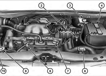
TO OPEN AND CLOSE THE HOOD To open the hood, two latches must be released. 1. Pull the hood release lever located on the instrument panel, below the steering column.
Hood Release Lever
154 UNDERSTANDING THE FEATURES OF YOUR VEHICLE 2. Move to the front of the vehicle and look inside the center of the hood opening. Locate, then push the safety catch lever to the right while raising the hood at the same time.
Safety Lever Location
Use the hood prop rod to secure the hood in the open position.
CAUTION!
To prevent possible damage, do not slam the hood to close it. Lower the hood until it is open approxi- mately 12 in (30 cm) and then drop it. This should secure both latches. Never drive your vehicle unless the hood is fully closed, with both latches engaged.
WARNING!
Be sure the hood is fully latched before driving your vehicle. If the hood is not fully latched, it could open when the vehicle is in motion and block your vision. Failure to follow this warning could result in serious injury or death.
LIGHTS All of the lights, except the Hazard Warning lights, headlight high beams and flash-to-pass, are controlled by switches to the left of the steering column on the instru- ment panel.
Headlight Switch With Halo Control
UNDERSTANDING THE FEATURES OF YOUR VEHICLE 155
Interior Lighting Interior lights are turned on when a door or liftgate is opened, the Remote Keyless Entry (RKE) transmitter is activated, or when the dimmer control is moved to the extreme top. The interior lights will automatically turn off in approxi- mately 10 minutes for the first activation and 90 seconds every activation thereafter until the engine is started, if one of the following occur: • A door, sliding door or the liftgate is left open • Any overhead reading light is left on NOTE: The key must be out of the ignition switch or the ignition switch must be in the OFF position for this feature to operate.
156 UNDERSTANDING THE FEATURES OF YOUR VEHICLE Dome Light Positions
Rotate the dimmer control completely upward to the second detent (extreme top position) to turn on the interior lights. The interior lights will remain on when the dimmer control is in this position.
Parade Mode (Daytime Brightness Feature)
feature brightens
Rotate the dimmer control to the first detent. This the odometer, radio and overhead dis- plays when the parking lights or head- lights are on.
Interior Lighting Defeat (Off)
Rotate the dimmer control to the off position (extreme bottom). The inte- rior lights will remain off when the doors or liftgate are open.
Dimmer Control
With the parking lights or headlights on, rotating the dimmer control for the interior lights on the instrument panel upward will increase the brightness of the instrument panel lights.
Halo Lights — If Equipped Halo lights are strategically placed soft lighting that help to illuminate specific areas to aid the occupants in locating specific features while driving at night.
To activate the Halo lights, push in the Halo switch control knob. Pressing the switch con- trol knob in a second time will turn the Halo lights off.
Parking Lights
Turn the headlight switch knob to the first detent to turn on the parking lights. This also turns on all
instrument panel lighting.
UNDERSTANDING THE FEATURES OF YOUR VEHICLE 157
Headlights
Turn the headlight switch knob to the second detent to turn the headlights and parking lights on. This also turns on all instrument panel lighting.
To change the brightness of the instrument panel lights, rotate the dimmer control up or down. Automatic Headlights — If Equipped This system automatically turns your headlights on or off based on ambient light levels. To turn the system on, turn the headlight switch to the extreme counterclockwise position aligning the indicator with the A (AUTO) on the headlight switch. When the system is on, the Headlight Time Delay feature is also on. This means your headlights will stay on for up to 90 seconds after you turn the
158 UNDERSTANDING THE FEATURES OF YOUR VEHICLE ignition switch OFF. To turn the Automatic System off, turn the headlight switch clockwise to the O (OFF) position.
Automatic Headlights
NOTE: The engine must be running before the head- lights will come on in the Automatic mode.
Headlights On With Wipers — If Equipped When your headlights are in the Automatic mode and the engine is running, the headlights will automatically turn on when the wiper system is also turned on. Headlights on when windshield wipers are on may be found on vehicles equipped with an automatic headlight system. Refer to “Electronic Vehicle Information Center (EVIC)/ Customer-Programmable Features” in “Understanding Your Instrument Panel” for further information. Headlight Delay — If Equipped This feature provides the safety of headlight illumination for up to 90 seconds after exiting your vehicle. To activate the delay feature, turn OFF the ignition switch while the headlights are still on. Then turn off the headlights within 45 seconds. The 90 second delay inter- val begins when headlight switch is turned off. If the headlights or parking lights are turned back on or the ignition switch is turned ON, the delay will be cancelled.
When exiting the vehicle the driver can choose to have the headlights remain on for 30, 60 or 90 seconds or not remain on. To change the timer setting, see your autho- rized dealer. The headlight delay time is programmable on vehicles equipped with an EVIC. Refer to “Electronic Vehicle Information Center (EVIC)/Customer-Programmable Features” in “Understanding Your Instrument Panel” for further information. If the headlights are turned off before the ignition, they will turn off in the normal manner. NOTE: The headlights must be turned off within 45 sec- onds of turning the ignition OFF to activate this feature.
UNDERSTANDING THE FEATURES OF YOUR VEHICLE 159
Lights-On Reminder If the headlights or the parking lights are left on, or if the dimmer control is in the extreme top position after the ignition switch is turned OFF, a chime will sound when the driver’s door is opened. Daytime Running Lights — If Equipped The headlights on your vehicle will illuminate when the engine is started and the transmission is in any gear except PARK. This provides a constant lights on condi- tion until the ignition is turned OFF. The lights illuminate at less than 50% of normal intensity. If the parking brake is applied, the Daytime Running Lights (DRL) will turn off. Also, if a turn signal is activated, the DRL lamp on the same side of the vehicle will turn off for the duration of the turn signal activation. Once the turn signal is no longer active, the DRL lamp will illuminate.
160 UNDERSTANDING THE FEATURES OF YOUR VEHICLE Front Fog Lights — If Equipped
To activate the front fog lights, turn on the parking lights or the low beam headlights and push in the headlight switch control knob. Pressing the head- light switch control knob in a second time will turn the front fog lights off. Battery Protection This feature provides battery protection to avoid wearing down the battery if the headlights, parking lights, or front fog lights are left on for extended periods of time when the ignition switch is in the LOCK position. After eight minutes of the ignition switch being in the LOCK position and the headlight switch in any position other than OFF or AUTO, the lights will turn off automatically until the next cycle of the ignition switch or headlight switch.
The battery protection feature will be disabled if the ignition switch is turned to any other position other than LOCK during the three minute delay. Multifunction Lever The multifunction lever is located on the left side of the steering column. The multifunction lever controls the: • Turn Signals • Headlight Beams Low/High • Flash-To-Pass (Optical Horn) • Front and Rear Wipers — Washer Functions Turn Signals Move the multifunction lever up or down and the arrows on each side of the instrument cluster flash to show proper operation of the front and rear turn signal lights.
UNDERSTANDING THE FEATURES OF YOUR VEHICLE 161
Turn Signal Warning If the vehicle electronics sense that the vehicle has traveled at over 18 mph (29 km/h) for about 1 mile (1.6 km) with the turn signals on, a chime will sound to alert the driver. Lane Change Assist Tap the lever up or down once, without moving beyond the detent, and the turn signal (right or left) will flash three times then automatically turn off. High/Low Beam Switch When the headlights are turned on, pushing the multi- function lever toward the instrument panel will switch from low beams to high beams. Pulling back to the neutral position returns the headlights to the low beam operation.
Turn Signals
If either light remains on and does not flash, or NOTE: there is a very fast flash rate, check for a defective outside light bulb. If an indicator fails to light when the lever is moved, the indicator bulb is defective.
it would suggest
that
162 UNDERSTANDING THE FEATURES OF YOUR VEHICLE Flash-To-Pass You can signal another vehicle with your headlights by lightly pulling the multifunction lever toward you. This will cause the headlights to turn on at high beam and remain on until the lever is released.
WINDSHIELD WIPER AND WASHERS The wipers and washers are operated by a switch within the multifunction lever. Rotate the end of the multifunc- tion lever to select the desired wiper speed. NOTE: Always remove any buildup of snow that pre- vents the windshield wiper blades from returning to the off position. If the windshield wiper switch is turned off and the blades cannot return to the off position, damage to the wiper motor may occur.
Washer And Wiper Controls
3 — Rear Wiper/Washer
1 — Front Mist/Washer 2 — Wiper Speeds 1. Mist, Front Wiper and Washer Press the end of the multifunction lever inward to the first detent and release to clear the windshield. Pressing the multifunction lever inward to the second detent will
cause the washers to spray for a maximum of 10 seconds, or until the multifunction lever is released, and the wipers will cycle three times. NOTE: • If the multifunction lever is pressed while in the delay range, the wipers will operate for several seconds after the multifunction lever is released, and then resume the intermittent interval previously selected. • If the multifunction lever is pressed while in the off position, the wipers will operate for approximately two or three wipe cycles and automatically turn off.
2. Intermittent, Low and High Speed Wipers Use the intermittent wipers when weather conditions make a single wiping cycle, with a variable pause be- tween cycles, desirable. Rotate the end of the multifunc- tion lever to the first detent position, then turn the end of the multifunction lever to select the desired delay inter- val. The delay can be regulated from approximately two
UNDERSTANDING THE FEATURES OF YOUR VEHICLE 163
seconds, to a maximum of 20 seconds between cycles. The time delay will be doubled if the vehicle speed is less than 10 mph (16 km/h). Low-speed is achieved by rotating the multifunction lever past the intermittent settings, to the first detent. High-speed is achieved by rotating the multifunction lever past the intermittent settings, to the second detent. 3. Rear Wiper and Washer Rotating the rotary ring to the first detent activates the rear intermittent wipers. To activate the washers, rotate the rotary ring fully forward and the washers will spray until the ring is released, and then resume the intermit- tent interval. NOTE: Rear window wipers function in the intermittent wiper speed only.164 UNDERSTANDING THE FEATURES OF YOUR VEHICLE
WARNING!
Sudden loss of visibility through the windshield could lead to an accident. You might not see other vehicles or other obstacles. To avoid sudden icing of the windshield during freezing weather, warm the windshield with the defroster before and during windshield washer use.
Rain Sensing Wipers — If Equipped This feature senses moisture on the windshield and automatically activates the wipers for the driver. This feature is especially useful for road splash or overspray from the windshield washers of the vehicle ahead. Rotate the end of the multifunction lever to one of the five intermittent wiper sensitivity settings to activate this feature.
The sensitivity of the system is adjustable from the multifunction lever. Wiper sensitivity position 3 has been calibrated for best overall wiping sensitivity. If the opera- tor desires more wiping sensitivity, they may select sensitivity positions 4 or 5. If the operator desires less wiping sensitivity, they may select sensitivity positions 2
or 1. Place the multifunction lever in the OFF position when not using the system. NOTE: • The Rain Sensing feature will not operate when the • The Rain Sensing feature may not function properly when ice or dried saltwater is present on the wind- shield. • Use of Rain-X威 or products containing wax or siliconewiper speed is in the low or high position.
may reduce rain sensor performance.
• The Rain Sensing feature can be turned on and off through the EVIC (if equipped). Refer to “Electronic Vehicle Information Center (EVIC)/Personal Settings (Customer-Programmable Features)” in “Understand- ing Your Instrument Panel” for further information.
The Rain Sensing system has protective features for the wiper blades and arms. It will not operate under the following conditions: • Low Temperature Wipe Inhibit — The Rain Sensing feature will not operate when the ignition is first switched ON, and the vehicle is stationary, and the outside temperature is below 32°F (0°C), unless the wiper control on the multifunction lever is moved, or the vehicle speed becomes greater than 0 mph (0 km/h), or the outside temperature rises above freezing.
UNDERSTANDING THE FEATURES OF YOUR VEHICLE 165
• Neutral Wipe Inhibit — The Rain Sensing feature will not operate when the ignition is ON, and the transmis- sion shift lever is in the NEUTRAL position, and the vehicle speed is less than 5 mph (8 km/h), unless the wiper control on the multifunction lever is moved or the shift lever is moved out of the NEUTRAL position. • Remote Start Mode Inhibit — On vehicles equipped with Remote Starting system, Rain Sensing wipers are not operational when the vehicle is in the remote start mode. Once the operator is in the vehicle and has placed the ignition switch in the RUN position, rain sensing wiper operation can resume, if it has been selected, and no other inhibit conditions (mentioned previously) exist.
TILT STEERING COLUMN This feature allows you to tilt the steering column upward or downward. The tilt control lever is located on the steering column, below the steering wheel.
166 UNDERSTANDING THE FEATURES OF YOUR VEHICLE To tilt the column, push the lever downward to the unlocked position. Move the steering column up or down, as desired. Pull the lever upward to the locked position to lock the steering column firmly in place.
Tilt Steering Column Lever
1 — Locked Position 2 — Unlocked Position
WARNING!
Do not adjust the steering column while driving. Adjusting the steering column while driving or driv- ing with the steering column unlocked, could cause the driver to lose control of the vehicle. Be sure the steering column is locked before driving your ve- hicle. Failure to follow this warning may result in serious injury or death.
ADJUSTABLE PEDALS — IF EQUIPPED This feature allows both the brake and accelerator pedals to move toward, or away, from the driver to provide improved position with the steering wheel. The adjust- able pedal system is designed to allow a greater range of driver comfort for steering wheel tilt and seat positions. The switch is located on the left side of the steering column.
UNDERSTANDING THE FEATURES OF YOUR VEHICLE 167
• The pedals cannot be adjusted when the vehicle is in REVERSE or when the Electronic Speed Control Sys- tem is on. The following messages will be displayed on vehicles equipped with the Electronic Vehicle In- formation System (EVIC) if the pedals are attempted to be adjusted when the system is locked out (“Adjust- able Pedal Disabled — Cruise Control Engaged” or “Adjustable Pedal Disabled — Vehicle In Reverse”.
CAUTION!
Do not place any article under the adjustable pedals or impede its ability to move, as it may cause damage to the pedal controls. Pedal travel may become lim- ited if movement is stopped by an obstruction in the adjustable pedal’s path.
Adjustable Pedal Switch
Press the button forward to move the pedals forward (toward the front of the vehicle). Press the button rearward to move the pedals rearward (toward the driver). • The pedals can be adjusted with the ignition OFF.
168 UNDERSTANDING THE FEATURES OF YOUR VEHICLE
WARNING!
Do not adjust the pedals while the vehicle is moving. You could lose control and have an accident. Always adjust the pedals while the vehicle is parked.
ELECTRONIC SPEED CONTROL — IF EQUIPPED When engaged, Electronic Speed Control takes over the accelerator operation at speeds greater than 25 mph (40 km/h).
Electronic Speed Control Lever
In order to ensure proper operation, the Elec- NOTE: tronic Speed Control System has been designed to shut down if multiple Speed Control functions are operated at the same time. If this occurs, the Electronic Speed Control System can be reactivated by pushing the Electronic Speed Control ON/OFF button and resetting the desired vehicle set speed.
To Activate Push the ON/OFF button (located in the end of the lever) once, and the cruise indicator light (located in the mes- sage window of the odometer) will illuminate, showing that the Electronic Speed Control system is on. To turn the Electronic Speed Control system off, push the ON/ OFF button a second time, and both the Electronic Speed Control system and indicator will turn off.
WARNING!
Leaving the Electronic Speed Control system on when not in use is dangerous. You could accidently set the system or cause it to go faster than you want. You could lose control and have an accident. Always leave the Electronic Speed Control system off when you are not using it.
UNDERSTANDING THE FEATURES OF YOUR VEHICLE 169
To Set At A Desired Speed Turn the Electronic Speed Control ON. When the vehicle has reached the desired speed, press the SET lever downward and then release. Lift your foot off the accel- erator and the vehicle will operate at the selected speed. Deactivating Electronic Speed Control A soft tap on the brake pedal or pulling the Electronic Speed Control lever (CANCEL) toward you will deacti- vate the Electronic Speed Control without erasing the set speed memory. Pushing the ON/OFF button to the OFF position or turning OFF the ignition erases the set speed memory. Resuming Speed To resume a previously set speed, raise the Electronic Speed Control lever (RESUME ACCEL) upward, and release. Resume can be used at any speed above 25 mph (40 km/h).
170 UNDERSTANDING THE FEATURES OF YOUR VEHICLE Varying The Speed Setting When the Electronic Speed Control is set, you can in- crease speed by pushing up and holding the RESUME ACCEL lever. If the lever is continually held in the RESUME ACCEL position, the set speed will continue to increase until the lever is released, then the new set speed will be established. Tapping the Electronic Speed Control lever to RESUME ACCEL once will result in a 1 mph (1.6 km/h) speed increase. Each time the lever is tapped speed increases, so tapping the lever three times will increase speed by 3 mph (4.8 km/h), etc. To decrease speed while Electronic Speed Control is set, push down and hold the Electronic Speed Control lever in SET DECEL. If the lever is continually held in the SET DECEL position, the set speed will continue to decrease until the lever is released. Release the lever when the desired speed is reached, and a new set speed will be established.
Tapping the Electronic Speed Control lever to SET DE- CEL once will result in a 1 mph (1.6 km/h) speed decrease. Each time the lever is tapped, speed decreases. Accelerating To Pass Press the accelerator as you normally would. When the pedal is released, the vehicle will return to the set speed. NOTE: The Electronic Speed Control system maintains speed up and down hills. A slight speed change on moderate hills is normal. Your vehicle may experience a downshift (automatic transmissions only) while climbing uphill or descending downhill. This downshift is necessary to maintain vehicle set speed. On steep hills, a greater speed loss or gain may occur, so it may be preferable to drive without Electronic Speed Control.
UNDERSTANDING THE FEATURES OF YOUR VEHICLE 171
ParkSense威 will remember the last system state (enabled or disabled) from the last ignition cycle when the ignition is changed to the RUN/ON position. ParkSense威 can be active only when the shift lever is in REVERSE. If ParkSense威 is enabled at this shift lever position, the system will be active until the vehicle speed is increased to approximately 11 mph (18 km/h) or above. The system will be active again if the vehicle speed is decreased to speeds less than approximately 10 mph (16 km/h).WARNING!
Electronic Speed Control can be dangerous where the system cannot maintain a constant speed. Your ve- hicle could go too fast for the conditions, and you could lose control. An accident could be the result. Do not use Electronic Speed Control in heavy traffic or on roads that are winding, icy, snow-covered, or slippery.
PARKSENSE姞 REAR PARK ASSIST — IF EQUIPPED The ParkSense威 Rear Park Assist system provides visual and audible indications of the distance between the rear fascia and the detected obstacle when backing up. Refer to ParkSense威 System Usage Precautions for limitations of this system and recommendations.
172 UNDERSTANDING THE FEATURES OF YOUR VEHICLE ParkSense姞 Sensors The ParkSense威 sensors, located in the rear fascia/ bumper, monitor the area behind the vehicle that is within the sensors’ field of view. The sensors can detect obstacles from approximately 12 in (30 cm) up to 79 in (200 cm) from the rear fascia/bumper in the horizontal direction, depending on the location, type and orientation of the obstacle. ParkSense姞 Warning Display The ParkSense威 Warning screen will only be displayed if Sound and Display is selected from the Customer- Programmable Features section of the Electronic Vehicle Information Center (EVIC). Refer to “Electronic Vehicle Information Center (EVIC)/Personal Settings (Customer- Programmable Features)” in “Understanding Your In- strument Panel” for further information.
The ParkSense威 Warning Display is located in the Instru- ment cluster’s EVIC display. It provides both visual and audible warnings to indicate the distance between the rear fascia/bumper and the detected obstacle.
ParkSense威 Warning Display
ParkSense姞 Display When the vehicle is in REVERSE, the warning display will turn ON indicating the system status.
UNDERSTANDING THE FEATURES OF YOUR VEHICLE 173
Park Assist ON
Park Assist Disabled
174 UNDERSTANDING THE FEATURES OF YOUR VEHICLE The system will indicate a detected obstacle by showing three solid arcs and will produce a 1⁄2 second tone. As the vehicle moves closer to the object the EVIC display will show fewer arcs and the sound tone will change from slow, to fast, to continuous.
Slow Tone
UNDERSTANDING THE FEATURES OF YOUR VEHICLE 175
Fast Tone
Continuous Tone
The vehicle is close to the obstacle when the EVIC display shows one flashing arc and sounds a continuous tone.
176 UNDERSTANDING THE FEATURES OF YOUR VEHICLE The following chart shows the warning display operation when the system is detecting an obstacle: WARNING DISPLAY DISTANCES
DISPLAY MESSAGE
OBSTACLE DISTANCE FROM:
ARC’s
AUDIBLE SIGNAL
Park Assist ON
Warning Object Detected Warning Object Detected Warning Object Detected Warning Object Detected Warning Object Detected Warning Object Detected Warning Object Detected
REAR CORNERS
REAR CENTER
27.5 in (70 cm) 25.5 in (65 cm) 19.7 in (50 cm) 15.7 in (40 cm) 11.8 in (30 cm)
78.7 in (200 cm) 39.3 in (100 cm) 31.4 in (80 cm) 25.5 in (65 cm) 19.7 in (50 cm) 15.7 in (40 cm) 11.8 in (30 cm)
None 3 Solid
3 Flashing 3 Flashing 2 Flashing 2 Flashing 2 Flashing 1 Flashing
None
Yes, 1/2 second
Slow Tone Slow Tone Fast Tone Fast Tone Fast Tone
Continuous Tone
NOTE: ParkSense威 will MUTE the radio, if on, when the system is sounding an audio tone.
Enabling/Disabling ParkSense姞 You can turn ParkSense威 ON or OFF through the EVIC. The available choices are: OFF, Sound Only, or Sound and Display. Refer to “Electronic Vehicle Information Center (EVIC)/Personal Settings (Customer-Programmable Fea- tures)” in “Understanding Your Instrument Panel” for further information. As soon as the system is disabled, the instrument cluster will display the “PARK ASSIST DISABLED” message, refer to “Electronic Vehicle Information Center (EVIC)” in “Understanding Your Instrument Panel” for further in- formation. When the shift lever is moved to REVERSE and the system is disabled, the EVIC will display the “PARK ASSIST DISABLED” message for as long as the vehicle is in REVERSE. Service ParkSense姞 When the ParkSense威 system is malfunctioning, the instrument cluster will actuate a single chime, once per
UNDERSTANDING THE FEATURES OF YOUR VEHICLE 177
ignition cycle, and it will display the “SERVICE PARK ASSIST SYSTEM” message. Refer to “Electronic Vehicle Information Center (EVIC)” in “Understanding Your Instrument Panel” for further information. When the shift lever is moved to REVERSE and the system has detected a faulted condition, the EVIC will display the “SERVICE PARK ASSIST SYSTEM” message for as long as the vehicle is in REVERSE. Under this condition ParkSense威 will not operate. If “SERVICE PARK ASSIST SYSTEM” appears in the Electronic Vehicle Information Center (EVIC) after mak- ing sure the rear fascia/bumper is free from snow, ice, mud, dirt and debris, see your authorized dealer. Cleaning ParkSense姞 Clean the ParkSense威 sensors with water, car wash soap and a soft cloth. Do not use rough or hard cloths. Do not scratch or poke the sensors. Otherwise, you could dam- age the sensors.178 UNDERSTANDING THE FEATURES OF YOUR VEHICLE ParkSense姞 System Usage Precautions NOTE: • Ensure that the rear bumper is free of dirt and debris to keep the ParkSense威 Rear Park Assist system oper- ating properly. • Jackhammers, large trucks, and other vibrations could • When you turn ParkSense威 off, the instrument cluster will display “PARK ASSIST DISABLED.” Further- more, once you turn ParkSense威 off, it remains off until you turn it on again, even if you cycle the ignition key.
affect the performance of the ParkSense威 system.
sounding a tone.
• When you move the shift lever to the REVERSE position and ParkSense威 is turned off, the instrument cluster will display “PARK ASSIST DISABLED” mes- sage for as long as the vehicle is in REVERSE. • ParkSense威, when on, will MUTE the radio when it is • If a ParkSense威 system malfunction occurs, a single chime will sound once per ignition cycle. In addition, the Electronic Vehicle Information Center (EVIC) will display “SERVICE PARK ASSIST SYSTEM”. If this occurs making sure the rear fascia/bumper is free from snow, ice, mud, dirt and debris, see your autho- rized dealer.
• Clean the ParkSense威 sensors regularly, taking care not to scratch or damage them. The sensors must not be covered with ice, snow, slush, mud, dirt, or debris. Failure to do so can result in the ParkSense威 system not working properly. The ParkSense威 system might not detect an obstacle behind the fascia/bumper, or it could provide a false indication that an obstacle is behind the fascia/bumper. • Objects must not be within 12 in (30 cm) from the rear fascia/bumper while driving the vehicle. Failure to do so can result in the system misinterpreting a close object as a sensor problem, causing the “SERVICE PARK ASSIST SYSTEM” message to be displayed in the instrument cluster.
UNDERSTANDING THE FEATURES OF YOUR VEHICLE 179
CAUTION!
• ParkSense威 is only a parking aid and it is unable to recognize every obstacle, including small ob- stacles. Parking curbs might be temporarily de- tected or not detected at all. Obstacles located above or below the ParkSense威 sensors will not be detected when they are in close proximity. • The vehicle must be driven slowly when using ParkSense威 to be able to stop in time when the obstacle is detected. It is recommended that the driver looks over his/her shoulder when using ParkSense威.
180 UNDERSTANDING THE FEATURES OF YOUR VEHICLE
WARNING!
• Drivers must be careful when backing up even when using the ParkSense威 Rear Park Assist sys- tem. Always check carefully behind your vehicle, look behind you, and be sure to check for pedes- trians, animals, other vehicles, obstructions, and blind spots before backing up. You are responsible for safety and must continue to pay attention to your surroundings. Failure to do so can result in serious injury or death.
(Continued)
WARNING! (Continued)
• Before using the ParkSense威 Rear Park Assist system, it is strongly recommended that the ball mount and hitch ball assembly is disconnected from the vehicle when the vehicle is not used for towing. Failure to do so can result in injury or damage to vehicles or obstacles because the hitch ball will be much closer to the obstacle than the rear fascia when the warning display turns on the single flashing arc and sounds the continuous tone. Also, the sensors could detect the ball mount and hitch ball assembly, depending on its size and shape, giving a false indication that an obstacle is behind the vehicle.
PARKVIEW姞 REAR BACK UP CAMERA — IF EQUIPPED Your vehicle may be equipped with the ParkView威 Rear Back Up Camera that allows you to see an on-screen image of the rear of your vehicle whenever the shift lever is put into REVERSE. The image will be displayed on the Navigation/Multimedia radio display screen. The Park- View威 camera is located in the light bar over the rear license plate.
UNDERSTANDING THE FEATURES OF YOUR VEHICLE 181
WARNING!
Drivers must be careful when backing up even when using the ParkView威 Rear Back Up Camera. Always check carefully behind your vehicle, and be sure to check for pedestrians, animals, other vehicles, ob- structions, or blind spots before backing up. You are responsible for the safety of your surroundings and must continue to pay attention while backing up. Failure to do so can result in serious injury or death.
CAUTION!
• To avoid vehicle damage, ParkView威 should only be used as a parking aid. The camera is unable to view every obstacle or object in your drive path.
(Continued)
182 UNDERSTANDING THE FEATURES OF YOUR VEHICLE
CAUTION! (Continued)
• To avoid vehicle damage, the vehicle must be driven slowly when using ParkView威 to be able to stop in time when an obstacle is seen. It is recom- mended that the driver look frequently over his/ her shoulder when using ParkView威.
If snow, ice, mud, or anything else builds up on NOTE: the camera lens, clean the lens, rinse with water, and dry with a soft cloth. Do not cover the lens. Turning ParkView姞 On or Off — With Navigation/Multimedia Radio 1. Press the “menu” hard key. 2. Select ⬙system setup⬙ soft key. 3. Press the “camera setup” soft key. 4. Enable or disable the rear camera feature by selecting “enable rear camera in reverse” soft key.
5. Press the “save” soft key. 6. When the vehicle is shifted into REVERSE, an image of the rear of the vehicle will appear with a caution note to “check entire surroundings” displayed across the top of the screen. After five seconds this note will disappear. 7. When the vehicle is shifted out of REVERSE, the rear camera mode is exited and the navigation or audio screen appears again. Turning ParkView姞 On or Off — Without Navigation/Multimedia Radio
1. Press the “menu” hard key. 2. Select “system setup” soft key. 3. Enable or disable the rear camera feature by selecting “enable rear camera in reverse” soft key. 4. When the vehicle is shifted into REVERSE, an image of the rear of the vehicle will appear with a caution note to
“check entire surroundings” displayed across the top of the screen. After five seconds this note will disappear. 5. When the vehicle is shifted out of REVERSE, the rear camera mode is exited and the audio screen appears again.
OVERHEAD CONSOLES
Front Overhead Console Two versions of the overhead console are available. The base front overhead console model featured fixed incan- descent courtesy/reading lights, flip-down sunglass stor- age and conversation mirror. The premium front over- head console model features a LED focused light that illuminates the instrument panel cupholders, Infrared Automatic Temperature Control Sensor (ATC equipped only), two swiveling LED lights, flip-down sunglass storage, conversation mirror, optional power sliding door switches and an optional power liftgate switch.
UNDERSTANDING THE FEATURES OF YOUR VEHICLE 183
NOTE: Premium sunroof console models include all of above except sunglass storage.Front Premium Overhead Console Features
1 — Cupholder LED 2 — ATC Sensor 3 — Interior Lights
4 — Storage/Mirror 5 — Switch Bank
184 UNDERSTANDING THE FEATURES OF YOUR VEHICLE Courtesy/Interior Lighting At the forward end of the console are two courtesy lights (standard dome light has two buttons). The lights turn on when a front door, a sliding door or the liftgate is opened. If your vehicle is equipped with Remote Keyless Entry (RKE) the lights will also turn on when the UNLOCK button on the RKE transmitter is pressed. The courtesy lights also function as reading lights. Press in on each lens to turn these lights on while inside the vehicle. Press a second time to turn each light off. You may adjust the direction of these lights by pressing the outside ring, which is identified with four directional arrows (LED lamps only). The area around the instrument panel cupholders is also illuminated from a light in the overhead console (pre- mium console only). This light is turned on when the headlight switch is on, and will adjust in brightness when the dimmer control is rotated up or down.
Sunglass Storage (non-sunroof only) At the rear of the front overhead console, a compartment is provided for the storage of two pairs of sunglasses. From the closed position, press the door over-travel latch to open the compartment. The door will slowly rotate to the full open position. From this position, the door can be fully closed or, by rotating upward about 3/4 of the way and releasing, positioned for conversation mirror use. From the ⬙conversation mirror⬙ position, the door can only be closed. To return to the full open position, the door must first be closed and then opened by pressing the over-travel latch again to release. NOTE: The front overhead console supplied with fac- tory sunroof, incorporates a sunroof switch. Rear Overhead Consoles — If Equipped The rear overhead storage system is available in two versions: with or without sunroof.
An additional LED at the front of the rear console shines down on the front foot-well area while in courtesy mode, for added convenience.
UNDERSTANDING THE FEATURES OF YOUR VEHICLE 185
Rear Courtesy/Reading Lights — If Equipped The overhead console has two sets of courtesy lights. The lights turn on when a front door, a sliding door or the liftgate is opened. If your vehicle is equipped with Remote Keyless Entry (RKE) the lights will also turn on when the UNLOCK button on the RKE transmitter is pressed. The courtesy lights also function as reading lights. Press in on each lens to turn these lights on while inside the vehicle. Press the lens a second time to turn each light off. You may adjust the direction of these lights by pressing the outside ring, which is identified with four directional arrows.
Overhead Compartment Features
1 — DVD 1
2 — Rear HVAC 3 — Interior Lights 4 — Storage 1 If equipped, otherwise storage.5 — Storage 6 — DVD 1
7 — Interior Lights 8 — Halo Lighting186 UNDERSTANDING THE FEATURES OF YOUR VEHICLE Rear Console Halo Lighting The rear overhead console has recessed halo lighting around the perimeter of the console base. This feature provides additional lighting options while traveling and is controlled by the headlight switch. Refer to “Lights/ Halo Lights — If Equipped” in “Understanding the Features Of Your Vehicle” for further information.
GARAGE DOOR OPENER — IF EQUIPPED HomeLink威 replaces up to three remote controls (hand- held transmitters) that operate devices such as garage door openers, motorized gates, lighting or home security systems. The HomeLink威 unit operates off your vehicle’s battery. The HomeLink威 buttons that are located in the headliner or sun visor designate the three different HomeLink威 channels.
HomeLink威 Buttons
NOTE: HomeLink威 is disabled when the Vehicle Secu- rity Alarm is active.
WARNING!
• Your motorized door or gate will open and close while you are training the universal transceiver. Do not train the transceiver if people, pets or other objects are in the path of the door or gate. Only use this transceiver with a garage door opener that has a “stop and reverse” feature as required by Federal safety standards. This includes most garage door opener models manufactured after 1982. Do not use a garage door opener without these safety features. Call toll-free 1–800–355–3515 or, on the Internet at www.HomeLink.com for safety infor- mation or assistance. • Vehicle exhaust contains carbon monoxide, a dan- gerous gas. Do not run your vehicle in the garage while training the transceiver. Exhaust gas can cause serious injury or death.
UNDERSTANDING THE FEATURES OF YOUR VEHICLE 187
Programming HomeLink姞
Before You Begin If you have not trained any of the HomeLink威 buttons, erase all channels before you begin training. To do this, press and hold the two outside buttons for up to 20 seconds until the red indicator flashes. It is recommended that a new battery be placed in the handheld transmitter of the device that is being copied to HomeLink威 for more efficient training and accurate transmission of the radio-frequency signal. Your vehicle should be parked outside of the garage when programming. Begin Programming 1. Turn the ignition switch to the ON/RUN position. 2. Hold the battery side of the handheld transmitter away from the HomeLink威 button you wish to program.
188 UNDERSTANDING THE FEATURES OF YOUR VEHICLE Place the handheld transmitter 1 to 3 in (3 to 8 cm) away from the HomeLink威 button you wish to program while keeping the indicator light in view. 3. Simultaneously press and hold both the chosen HomeLink威 button and the handheld transmitter button until the HomeLink威 indicator changes from a slow to a rapidly blinking light, then release both the HomeLink威 and handheld transmitter buttons. Watch for the HomeLink威 indicator to change flash rates. When it changes, it is programmed. It may take up to 30 seconds or longer in rare cases. The garage door may open and close while you train. NOTE: • Some gate operators and garage door openers may require you to replace Step 3 with procedures noted in the “Gate Operator/Canadian Programming” section.
• After training a HomeLink威 channel, if the garage door does not operate with HomeLink威 and the ga- rage door opener was manufactured after 1995, the garage door opener may have a rolling code. If so, proceed to Step 5 “Programming A Rolling Code System.”
4. Press and hold the just-trained HomeLink威 button and observe the indicator light. If the indicator light stays on constantly, programming is complete and the garage door (or device) should activate when the HomeLink威 button is pressed. If the indicator light blinks rapidly for two seconds and then turns to a constant light, proceed to Step 5 “Pro- gramming A Rolling Code System.” 5. Programming A Rolling Code System At the garage door opener motor (in the garage), locate the “Learn” or “Training” button.
This can usually be found where the hanging antenna wire is attached to the garage door opener motor. It is NOT the button normally used to open and close the door.
Training The Garage Door Opener
1 — Door Opener 2 — Training Button
UNDERSTANDING THE FEATURES OF YOUR VEHICLE 189
6. Firmly press and release the LEARN or TRAINING button. The name and color of the button may vary by manufacturer. NOTE: You have 30 seconds in which to initiate the next step after the LEARN button has been pressed. 7. Return to the vehicle and press the programmed HomeLink威 button twice (holding the button for two seconds each time). If the device is plugged in and activates, programming is complete. If the device does not activate, press the button a third time (for two seconds) to complete the training. If you have any problems, or require assistance, please call toll-free 1–800–355–3515 or, on the Internet at www.HomeLink.com for information or assistance. To program the remaining two HomeLink威 buttons, repeat each step for each remaining button. DO NOT