- 2011 Dodge Durango Owners Manuals
- Dodge Durango Owners Manuals
- 2008 Dodge Durango Owners Manuals
- Dodge Durango Owners Manuals
- 2009 Dodge Durango Owners Manuals
- Dodge Durango Owners Manuals
- 2007 Dodge Durango Owners Manuals
- Dodge Durango Owners Manuals
- 2004 Dodge Durango Owners Manuals
- Dodge Durango Owners Manuals
- 2013 Dodge Durango Owners Manuals
- Dodge Durango Owners Manuals
- 2005 Dodge Durango Owners Manuals
- Dodge Durango Owners Manuals
- 2006 Dodge Durango Owners Manuals
- Dodge Durango Owners Manuals
- 2012 Dodge Durango Owners Manuals
- Dodge Durango Owners Manuals
- Download PDF Manual
-
and California reformulated gasoline.
Materials Added To Fuel All gasoline sold in the United States is required to contain effective detergent additives. Use of additional detergents or other additives is not needed under normal conditions and they would result in additional cost. Therefore, you should not have to add anything to the fuel. Fuel System Cautions
CAUTION!
Follow these guidelines to maintain your vehicle’s performance: • The use of leaded gas is prohibited by Federal law. Using leaded gasoline can impair engine perfor- mance and damage the emissions control system.
(Continued)
STARTING AND OPERATING 539
CAUTION! (Continued)
• An out-of-tune engine or certain fuel or ignition malfunctions can cause the catalytic converter to overheat. If you notice a pungent burning odor or some light smoke, your engine may be out of tune or malfunctioning and may require immediate service. Contact your authorized dealer for service assistance. • The use of fuel additives, which are now being sold as octane enhancers, is not recommended. Most of these products contain high concentrations of methanol. Fuel system damage or vehicle perfor- mance problems resulting from the use of such fuels or additives is not the responsibility of the manufacturer.
NOTE: Intentional tampering with the emissions control system can result in civil penalties being assessed against you.
540 STARTING AND OPERATING Carbon Monoxide Warnings
WARNING!
Carbon monoxide (CO) in exhaust gases is deadly. Follow the precautions below to prevent carbon monoxide poisoning: • Do not inhale exhaust gases. They contain carbon monoxide, a colorless and odorless gas, which can kill. Never run the engine in a closed area, such as a garage, and never sit in a parked vehicle with the engine running for an extended period. If the vehicle is stopped in an open area with the engine running for more than a short period, adjust the ventilation system to force fresh, outside air into the vehicle.
(Continued)
WARNING! (Continued)
• Guard against carbon monoxide with proper main- tenance. Have the exhaust system inspected every time the vehicle is raised. Have any abnormal conditions repaired promptly. Until repaired, drive with all side windows fully open.
FLEXIBLE FUEL (3.6L ENGINE ONLY) — IF EQUIPPED
E-85 General Information The information in this section is for Flexible Fuel ve- hicles only. These vehicles can be identified by a unique fuel filler door label that states Ethanol (E-85) or Un- leaded Gasoline Only. This section only covers those subjects that are unique to these vehicles. Please refer to the other sections of this manual for information on features that are common between Flexible Fuel and gasoline-only powered vehicles.
STARTING AND OPERATING 541
E-85 Badge
E-85 Fuel Cap
CAUTION!
Only vehicles with the E-85 fuel filler door label can operate on E-85.
542 STARTING AND OPERATING Ethanol Fuel (E-85) E-85 is a mixture of approximately 85% fuel ethanol and 15% unleaded gasoline.
WARNING!
Ethanol vapors are extremely flammable and could cause serious personal injury. Never have any smok- ing materials lit in or near the vehicle when remov- ing the fuel filler tube cap (gas cap) or filling the tank. Do not use E-85 as a cleaning agent and never use it near an open flame.
Fuel Requirements If your vehicle is E-85 compatible, it will operate on unleaded gasoline with an octane rating of 87, or E-85
fuel, or any mixture of these two fuels.For best results, a refueling pattern that avoids alternat- ing between E-85 and unleaded gasoline is recom- mended. When you do switch fuel types it is recommended that: • you do not add less than 5 gallons (19 Liters) when • you drive the vehicle immediately after refueling for at
refueling
least 5 miles (8 km)
Observing these precautions will avoid possible hard starting and/or significant deterioration in driveability during warm up. NOTE: • Use seasonally adjusted E-85 fuel (ASTM D5798). With non-seasonally adjusted E-85 fuel, you may experience hard starting and rough idle following start up even if the above recommendations are followed, especially when the ambient temperature is below 32°F (0°C).
• Some additives used in regular gasoline are not fully compatible with E-85 and may form deposits in your engine. To eliminate driveability issues that may be caused by these deposits, a supplemental gasoline additive, such as MOPAR® Injector Cleanup or Techron may be used.
Selection Of Engine Oil For Flexible Fuel Vehicles (E-85) And Gasoline Vehicles FFV vehicles operated on E-85 require specially formu- lated engine oils. These special requirements are included in MOPAR® engine oils, and in equivalent oils meeting Chrysler Specification MS-6395. The manufacturer only recommends engine oils that are API Certified and meet the requirements of Material Standard MS-6395. MS-6395
contains additional requirements, developed during ex- tensive fleet testing, to provide additional protection to Chrysler Group LLC engines. Use MOPAR® or an equivalent oil meeting the specification MS-6395.STARTING AND OPERATING 543
Starting The characteristics of E-85 fuel make it unsuitable for use when ambient temperatures fall below 0°F (-18°C). In the range of 0°F (-18°C) to 32°F (0°C), you may experience an increase in the time it takes for your engine to start, and a deterioration in driveability (sags and/or hesitations) until the engine is fully warmed up. NOTE: Use of the engine block heater (if equipped) is beneficial for E-85 startability when the ambient tempera- ture is less than 32°F (0°C). Cruising Range Because E-85 fuel contains less energy per gallon/liter than gasoline, you will experience an increase in fuel consumption. You can expect your miles per gallon (mpg)/miles per liter and your driving range to decrease by about 30%, compared to gasoline operation.
ADDING FUEL
Fuel Filler Cap (Gas Cap) The gas cap is located behind the locking fuel filler door, on the driver’s side of the vehicle. If the gas cap is lost or damaged, be sure the replacement cap is for use with this vehicle. 1. Press the fuel filler door release switch (located under
the headlamp switch).
544 STARTING AND OPERATING Replacement Parts Many components in your Flexible Fuel Vehicle (FFV) are designed to be compatible with ethanol. Always be sure that your vehicle is serviced with correct ethanol com- patible parts.
CAUTION!
Replacing fuel system components with non-ethanol compatible components can damage your vehicle.
Maintenance
CAUTION!
Do not use ethanol mixture greater than 85% in your vehicle. It will cause difficulty in cold starting and may affect driveability.
STARTING AND OPERATING 545
Fuel Filler Door Release Switch
Fuel Filler Cap
2. Open the fuel filler door, and remove the fuel filler
cap.
546 STARTING AND OPERATING
CAUTION!
• Damage to the fuel system or emission control system could result from using an improper fuel cap (gas cap). A poorly fitting cap could let impu- rities into the fuel system. Also, a poorly fitting aftermarket cap can cause the “Malfunction Indi- cator Light (MIL)” to illuminate, due to fuel vapors escaping from the system. • A poorly fitting gas cap may cause the MIL to turn on. • To avoid fuel spillage and overfilling, do not “top off” the fuel tank after filling.
WARNING!
• Never have any smoking materials lit in or near the vehicle when the gas cap is removed or the tank is being filled.
(Continued)
WARNING! (Continued)
• Never add fuel when the engine is running. This is in violation of most state and federal fire regula- tions and may cause the malfunction indicator light to turn on. • A fire may result if gasoline is pumped into a portable container that is inside of a vehicle. You could be burned. Always place gas containers on the ground while filling.
is full.
NOTE: • When the fuel nozzle “clicks” or shuts off, the fuel tank • Tighten the gas cap about one-quarter turn until you hear one click. This is an indication that the cap is properly tightened.
• If the gas cap is not tighten properly, the MIL will come on. Be sure the gas cap is tightened every time the vehicle is refueled.
Emergency Fuel Filler Door Release If you are unable to open the fuel filler door, use the fuel filler door emergency release. 1. Open the liftgate. 2. Push down on the inboard edge of the left storage bin,
this will pop up the outboard edge.
3. Grab popped up outboard edge with other hand to
disengage snaps.
4. Remove the storage bin. 5. Pull the release cable.
STARTING AND OPERATING 547
Release Cable Loose Fuel Filler Cap Message
If the vehicle diagnostic system determines that the fuel filler cap is loose, improperly installed, or damaged, a loose gascap indicator will display in the EVIC telltale display area.
548 STARTING AND OPERATING Refer to “Electronic Vehicle Information Center (EVIC)” in “Understanding Your Instrument Panel” for further information. Tighten the fuel filler cap properly and press the SELECT button to turn off the message. If the problem continues, the message will appear the next time the vehicle is started.
VEHICLE LOADING
Certification Label As required by National Highway Traffic Safety Admin- istration regulations, your vehicle has a certification label affixed to the driver’s side door or pillar. This label contains the month and year of manufacture, Gross Vehicle Weight Rating (GVWR), Gross Axle Weight Rating (GAWR) front and rear, and Vehicle Identification Number (VIN). A Month-Day-Hour (MDH) number is in- cluded on this label and indicates the Month, Day and Hour of manufacture. The bar code that appears on the bottom of the label is your VIN.
Gross Vehicle Weight Rating (GVWR) The GVWR is the total permissible weight of your vehicle including driver, passengers, vehicle, options and cargo. The label also specifies maximum capacities of front and rear axle systems (GAWR). Total load must be limited so GVWR and front and rear GAWR are not exceeded. Payload The payload of a vehicle is defined as the allowable load weight a truck can carry, including the weight of the driver, all passengers, options and cargo. Gross Axle Weight Rating (GAWR) The GAWR is the maximum permissible load on the front and rear axles. The load must be distributed in the cargo area so that the GAWR of each axle is not exceeded.
Each axle GAWR is determined by the components in the system with the lowest load carrying capacity (axle, springs, tires or wheels). Heavier axles or suspension components sometimes specified by purchasers for in- creased durability does not necessarily increase the vehi- cle’s GVWR. Tire Size The tire size on the Vehicle Certification Label represents the actual tire size on your vehicle. Replacement tires must be equal to the load capacity of this tire size. Rim Size This is the rim size that is appropriate for the tire size listed. Inflation Pressure This is the cold tire inflation pressure for your vehicle for all loading conditions up to full GAWR.
STARTING AND OPERATING 549
Curb Weight The curb weight of a vehicle is defined as the total weight of the vehicle with all fluids, including vehicle fuel, at full capacity conditions, and with no occupants or cargo loaded into the vehicle. The front and rear curb weight values are determined by weighing your vehicle on a commercial scale before any occupants or cargo are added. Loading The actual total weight and the weight of the front and rear of your vehicle at the ground can best be determined by weighing it when it is loaded and ready for operation. The entire vehicle should first be weighed on a commer- cial scale to insure that the GVWR has not been exceeded. The weight on the front and rear of the vehicle should then be determined separately to be sure that the load is properly distributed over the front and rear axle. Weigh- ing the vehicle may show that the GAWR of either the
550 STARTING AND OPERATING front or rear axles has been exceeded but the total load is within the specified GVWR. If so, weight must be shifted from front to rear or rear to front as appropriate until the specified weight limitations are met. Store the heavier items down low and be sure that the weight is distributed equally. Stow all loose items securely before driving. Improper weight distributions can have an adverse effect on the way your vehicle steers and handles and the way the brakes operate.
CAUTION!
Do not load your vehicle any heavier than the GVWR or the maximum front and rear GAWR. If you do, parts on your vehicle can break, or it can change the way your vehicle handles. This could cause you to lose control. Also overloading can shorten the life of your vehicle.
TRAILER TOWING In this section you will find safety tips and information on limits to the type of towing you can reasonably do with your vehicle. Before towing a trailer, carefully review this information to tow your load as efficiently and safely as possible. To maintain warranty coverage, follow the requirements and recommendations in this manual concerning ve- hicles used for trailer towing. Common Towing Definitions The following trailer towing related definitions will assist you in understanding the following information: Gross Vehicle Weight Rating (GVWR) The GVWR is the total allowable weight of your vehicle. This includes driver, passengers, cargo and tongue weight. The total load must be limited so that you do not
exceed the GVWR. Refer to “Vehicle Loading/Vehicle Certification Label” in “Starting and Operating” for further information. Gross Trailer Weight (GTW) The GTW is the weight of the trailer plus the weight of all cargo, consumables and equipment (permanent or tem- porary) loaded in or on the trailer in its ⬙loaded and ready for operation⬙ condition. The recommended way to measure GTW is to put your fully loaded trailer on a vehicle scale. The entire weight of the trailer must be supported by the scale.
STARTING AND OPERATING 551
WARNING!
If the gross trailer weight is 3,500 lbs (1 587 kg) or more, it is mandatory to use a weight-distributing hitch to ensure stable handling of your vehicle. If you use a standard weight-carrying hitch, you could lose control of your vehicle and cause a collision.
Gross Combination Weight Rating (GCWR) The GCWR is the total permissible weight of your vehicle and trailer when weighed in combination. NOTE: The GCWR rating includes a 150 lbs (68 kg) allowance for the presence of a driver. Gross Axle Weight Rating (GAWR) The GAWR is the maximum capacity of the front and rear axles. Distribute the load over the front and rear axles evenly. Make sure that you do not exceed either front or
552 STARTING AND OPERATING rear GAWR. Refer to “Vehicle Loading/Vehicle Certifica- tion Label” in “Starting and Operating” for further information.
WARNING!
It is important that you do not exceed the maximum front or rear GAWR. A dangerous driving condition can result if either rating is exceeded. You could lose control of the vehicle and have a collision.
Tongue Weight (TW) The tongue weight is the downward force exerted on the hitch ball by the trailer. In most cases it should not be more than 10% of the trailer load. You must consider this as part of the load on your vehicle. Frontal Area The frontal area is the maximum height multiplied by the maximum width of the front of a trailer.
Trailer Sway Control The trailer sway control can be a mechanical telescoping link that can be installed between the hitch receiver and the trailer tongue that typically provides adjustable fric- tion associated with the telescoping motion to dampen any unwanted trailer swaying motions while traveling. If equipped, the electronic Trailer Sway Control (TSC) recognizes a swaying trailer and automatically applies individual wheel brakes and/or reduces engine power to attempt to eliminate the trailer sway. Weight-Carrying Hitch A weight-carrying hitch supports the trailer tongue weight, just as if it were luggage located at a hitch ball or some other connecting point of the vehicle. These kinds of hitches are the most popular on the market today and they are commonly used to tow small- and medium- sized trailers.
STARTING AND OPERATING 553
WARNING!
• An improperly adjusted weight-distributing hitch system may reduce handling, stability, and braking performance, and could result in a collision. • Weight-distributing hitch systems may not be com- patible with Surge Brake Couplers. Consult with your hitch and trailer manufacturer or a reputable Recreational Vehicle dealer for additional informa- tion.
Weight-Distributing Hitch A weight-distributing system works by applying lever- age through spring (load) bars. They are typically used for heavier loads, to distribute trailer tongue weight to the tow vehicle’s front axle and the trailer axle(s). When used in accordance with the manufacturers’ directions, it provides for a more level ride, offering more consistent steering and brake control thereby enhancing towing safety. The addition of a friction/hydraulic sway control also dampens sway caused by traffic and crosswinds and contributes positively to tow vehicle and trailer stability. Trailer sway control and a weight distributing (load equalizing) hitch are recommended for heavier Tongue Weights (TW) and may be required depending on Vehicle and Trailer configuration/loading to comply with gross axle weight rating (GAWR) requirements.
554 STARTING AND OPERATING
Without Weight-Distributing Hitch (Incorrect)
With Weight-Distributing Hitch (Correct)
STARTING AND OPERATING 555
Trailer Hitch Classification Definitions
Class
Max. Trailer Hitch Industry Standards 2,000 lbs (907 kg) 3,500 lbs (1 587 kg) 5,000 lbs (2 268 kg) 10,000 lbs (4 540 kg)
Class I - Light Duty Class II - Medium Duty Class III - Heavy Duty Class IV - Extra Heavy Duty Refer to the “Trailer Towing Weights (Maximum Trailer Weight Ratings)” chart for the Maximum Gross Trailer Weight (GTW) towable for your given drivetrain. All trailer hitches should be professionally installed on your vehicle.
Improper Adjustment Of Weight-Distributing Hitch
(Incorrect)
Trailer Hitch Classification The following chart provides the industry standard for the maximum trailer weight a given trailer hitch class can tow and should be used to assist you in selecting the correct trailer hitch for your intended towing condition.
556 STARTING AND OPERATING Trailer Towing Weights (Maximum Trailer Weight Ratings) The following chart provides the maximum trailer weight ratings towable for your given drivetrain.
Engine
Model
3.6L
3.6L
5.7L
5.7L
RWD
AWD
RWD
AWD
GCWR (Gross
Combined Wt. Rating) 11,600 lbs (5 262 kg) 11,600 lbs (5 262 kg) 13,100 lbs (5 942 kg) 13,100 lbs (5 942 kg)
Frontal Area
Max. GTW (Gross
Max. Trailer Tongue
Trailer Wt.)
Wt. (See Note)
40 sq ft
(3.72 sq m)
40 sq ft
(3.72 sq m)
60 sq ft
(5.57 sq m)
60 sq ft
(5.57 sq m)
6,200 lbs (2 812 kg)
620 lbs (281 kg)
6,200 lbs (2 812 kg)
620 lbs (281 kg)
7,200 lbs (3 266 kg)
720 lbs (327 kg)
7,200 lbs (3 266 kg)
720 lbs (327 kg)
Refer to local laws for maximum trailer towing speeds.
STARTING AND OPERATING 557
wheels or heavier in the rear can cause the trailer to sway severely side to side which will cause loss of control of the vehicle and trailer. Failure to load trailers heavier in front is the cause of many trailer collisions. Never exceed the maximum tongue weight stamped on your trailer hitch.NOTE: • The trailer tongue weight must be considered as part of the combined weight of occupants and cargo, and should never exceed the weight referenced on the Tire and Loading Information placard. Refer to “Tire Safety Infor- mation” in “Starting and Operating” for further informa- tion. The addition of passengers and cargo may require reducing trailer tongue load and Gross Trailer Weight (GTW). Redistributing cargo (to the trailer) may be nec- essary to avoid exceeding Rear Gross Axle Weight Rating (GAWR) of 3,900 lbs (1 769 kg). • Vehicles not factory equipped with trailer tow package
are limited to 3,500 lbs (350 lbs tongue weight).
Trailer And Tongue Weight Always load a trailer with 60% to 65% of the weight in the front of the trailer. This places 10% to 15% of the GTW on the tow hitch of your vehicle. Loads balanced over the
put in or on your vehicle
558 STARTING AND OPERATING Consider the following items when computing the weight on the rear axle of the vehicle: • The tongue weight of the trailer • The weight of any other type of cargo or equipment • The weight of the driver and all passengers. NOTE: Remember that everything put into or on the trailer adds to the load on your vehicle. Also, additional factory-installed options or dealer-installed options must be considered as part of the total load on your vehicle. Refer to “Tire Safety Information/Tire and Loading In- formation Placard” in “Starting and Operating” for fur- ther information.
Towing Requirements To promote proper break-in of your new vehicle drive- train components, the following guidelines are recom- mended.
CAUTION!
• Do not tow a trailer at all during the first 500 miles (805 km) the new vehicle is driven. The engine, axle or other parts could be damaged. • Then, during the first 500 miles (805 km) that a trailer is towed, do not drive over 50 mph (80 km/h) and do not make starts at full throttle. This helps the engine and other parts of the vehicle wear in at the heavier loads.
Perform the maintenance listed in the “Maintenance Schedule.” Refer to “Maintenance Schedule” for the proper maintenance intervals. When towing a trailer, never exceed the GAWR or GCWR ratings.
WARNING!
Improper towing can lead to a collision. Follow these guidelines to make your trailer towing as safe as possible: • Make certain that the load is secured in the trailer and will not shift during travel. When trailering cargo that is not fully secured, dynamic load shifts can occur that may be difficult for the driver to control. You could lose control of your vehicle and have a collision.
(Continued)
STARTING AND OPERATING 559
WARNING! (Continued)
• When hauling cargo or towing a trailer, do not overload your vehicle or trailer. Overloading can cause a loss of control, poor performance or dam- age to brakes, axle, engine, transmission, steering, suspension, chassis structure or tires. • Safety chains must always be used between your vehicle and trailer. Always connect the chains to the hook retainers of the vehicle hitch. Cross the chains under the trailer tongue and allow enough slack for turning corners. • Vehicles with trailers should not be parked on a grade. When parking, apply the parking brake on the tow vehicle. Put the tow vehicle transmission in PARK. For four-wheel drive vehicles, make sure the transfer case is not in NEUTRAL. Always, block or ⴖchockⴖ the trailer wheels.
(Continued)
560 STARTING AND OPERATING
WARNING! (Continued)
• GCWR must not be exceeded. • Total weight must be distributed between the tow vehicle and the trailer such that the following four ratings are not exceeded: 1. GVWR 2. GTW 3. GAWR 4. Trailer tongue weight rating for the trailer hitch utilized .
Towing Requirements – Tires • Do not attempt to tow a trailer while using a compact • Proper tire inflation pressures are essential to the safe and satisfactory operation of your vehicle. Refer to
spare tire.
sures before trailer usage.
“Tires – General Information” in “Starting and Oper- ating” for proper tire inflation procedures. • Check the trailer tires for proper tire inflation pres- • Check for signs of tire wear or visible tire damage before towing a trailer. Refer to “Tires – General Information” in “Starting and Operating” for the proper inspection procedure. • When replacing tires, refer to “Tires – General Infor- mation” in “Starting and Operating” for the proper tire replacement procedures. Replacing tires with a higher load carrying capacity will not increase the vehicle’s GVWR and GAWR limits.
Towing Requirements – Trailer Brakes • Do not interconnect the hydraulic brake system or vacuum system of your vehicle with that of the trailer. This could cause inadequate braking and possible personal injury. • An electronically actuated trailer brake controller is required when towing a trailer with electronically actuated brakes. When towing a trailer equipped with a hydraulic surge actuated brake system, an electronic brake controller is not required. • Trailer brakes are recommended for trailers over 1,000 lbs (454 kg) and required for trailers in excess of 2,000 lbs (907 kg).
STARTING AND OPERATING 561
CAUTION!
If the trailer weighs more than 1,000 lbs (454 kg) loaded, it should have its own brakes and they should be of adequate capacity. Failure to do this could lead to accelerated brake lining wear, higher brake pedal effort, and longer stopping distances.
WARNING!
• Do not connect trailer brakes to your vehicle’s hy- draulic brake lines. It can overload your brake sys- tem and cause it to fail. You might not have brakes when you need them and could have a collision. • Towing any trailer will increase your stopping distance. When towing you should allow for addi- tional space between your vehicle and the vehicle in front of you. Failure to do so could result in a collision.
562 STARTING AND OPERATING Towing Requirements – Trailer Lights And Wiring Whenever you pull a trailer, regardless of the trailer size, stoplights and turn signals on the trailer are required for motoring safety. The Trailer Tow Package may include a four- and seven- pin wiring harness. Use a factory approved trailer har- ness and connector. NOTE: Do not cut or splice wiring into the vehicles wiring harness. The electrical connections are all complete to the vehicle but you must mate the harness to a trailer connector. Refer to the following illustrations.
Four-Pin Connector
1 — Female Pins 2 — Male Pin 3 — Ground
4 — Park 5 — Left Stop/Turn 6 — Right Stop/Turn
STARTING AND OPERATING 563
Towing Tips Before setting out on a trip, practice turning, stopping and backing the trailer up in an area away from heavy traffic. Automatic Transmission The DRIVE range can be selected when towing. The transmission controls include an adaptive drive strategy to avoid frequent shifting when towing. However, if frequent shifting does occur while in DRIVE, select TOW/HAUL mode (if equipped), or a lower gear range (using the Electronic Range Select [ERS] shift control). NOTE: Using the TOW/HAUL mode (if equipped) or selecting a lower gear range (using the ERS shift control) while operating the vehicle under heavy loading condi- tions, will improve performance and extend transmission life by reducing excessive shifting and heat buildup. This action will also provide better engine braking.
Seven-Pin Connector
1 — Battery 2 — Backup Lamps 3 — Right Stop/Turn 4 — Electric Brakes
5 — Ground 6 — Left Stop/Turn 7 — Running Lamps
564 STARTING AND OPERATING If you REGULARLY tow a trailer for more than 45
minutes of continuous operation, then change the trans- mission fluid and filter(s) as specified for “police, taxi, fleet, or frequent trailer towing.” Refer to the “Mainte- nance Schedule” for the proper maintenance intervals. NOTE: Check the transmission fluid level before towing (5.7L engine). Electronic Speed Control – If Equipped • Do not use in hilly terrain or with heavy loads. • When using the speed control, if you experience speed drops greater than 10 mph (16 km/h), disengage until you can get back to cruising speed. • Use speed control in flat terrain and with light loads tomaximize fuel efficiency.
Cooling System To reduce potential for engine and transmission over- heating, take the following actions: City Driving When stopped for short periods of time, shift the trans- mission into NEUTRAL and increase engine idle speed. Highway Driving Reduce speed. Air Conditioning Turn off temporarily.
SNOW PLOW Snow plows, winches, and other aftermarket equipment should not be added to the front end of your vehicle. The airbag crash sensors may be affected by the change in the front end structure. The airbags could deploy unexpect- edly or could fail to deploy during a collision.
STARTING AND OPERATING 565
WARNING!
Do not add a snow plow, winches, or any other aftermarket equipment to the front of your vehicle. This could adversely affect the functioning of the airbag system and you could be injured.
566 STARTING AND OPERATING RECREATIONAL TOWING (BEHIND MOTORHOME, ETC.) Towing This Vehicle Behind Another Vehicle
Towing Condition
Wheels OFF the
Flat Tow
Dolly Tow
On Trailer
Ground NONE
Front
Rear ALL
Rear-Wheel Drive Models
NOT
ALLOWED
NOT
ALLOWED
OK OK
All-Wheel Drive Models
• See Instructions • Transmission in PARK • Transfer case in NEUTRAL (N) • Tow in forward direction NOT ALLOWED
NOT ALLOWED
OK
Recreational Towing – Rear-Wheel Drive Models DO NOT flat tow this vehicle. Damage to the drivetrain will result. Recreational towing (for two-wheel drive models) is allowed ONLY if the rear wheels are OFF the ground. This may be accomplished using a tow dolly or vehicle trailer. If using a tow dolly, follow this procedure: 1. Properly secure the dolly to the tow vehicle, following
the dolly manufacturer’s instructions.
2. Drive the rear wheels onto the tow dolly. 3. Firmly apply the parking brake. Shift the transmission
into PARK.
4. Turn the engine OFF and remove the key fob from the
ignition switch.
5. Properly secure the rear wheels to the dolly, following
the dolly manufacturer’s instructions.
STARTING AND OPERATING 567
6. Install a suitable clamping device, designed for tow- ing, to secure the front wheels in the straight position.CAUTION!
Towing with the rear wheels on the ground will cause severe transmission damage. Damage from improper towing is not covered under the New Vehicle Limited Warranty.
Recreational Towing – All-Wheel Drive Models (Single-Speed Transfer Case) Recreational towing is not allowed. These models do not have a NEUTRAL (N) position in the transfer case. NOTE: This vehicle may be towed on a flatbed or vehicle trailer provided all four wheels are OFF the ground.
568 STARTING AND OPERATING
CAUTION!
Towing this vehicle in violation of the above require- ments can cause severe transmission and/or transfer case damage. Damage from improper towing is not covered under the New Vehicle Limited Warranty.
Recreational Towing – All-Wheel Drive Models (Two-Speed Transfer Case) The transfer case must be shifted into NEUTRAL (N) and the transmission must be in PARK for recreational tow- ing. The NEUTRAL (N) selection button is adjacent to the transfer case selector switch. Shifts into and out of transfer case NEUTRAL (N) can take place with the selector switch in any mode position.
CAUTION!
• Front or rear wheel lifts should not be used. Inter- nal damage to the transmission or transfer case will occur if a front or rear wheel lift is used when recreational towing. • Tow only in the forward direction. Towing this vehicle backwards can cause severe damage to the transfer case. • The transmission must be in PARK for recreational towing. • Before recreational towing, perform the procedure outlined under “Shifting Into NEUTRAL (N)” to be certain that the transfer case is fully in NEU- TRAL (N). Otherwise, internal damage will result.
(Continued)
CAUTION! (Continued)
• Failure to follow these procedures can cause severe transmission and/or transfer case damage. Damage from improper towing is not covered under the New Vehicle Limited Warranty. • Do not use a bumper-mounted clamp-on tow bar on your vehicle. The bumper face bar will be damaged.
STARTING AND OPERATING 569
Shifting Into NEUTRAL (N)
WARNING!
You or others could be injured if you leave the vehicle unattended with the transfer case in the NEUTRAL (N) position without first fully engaging the parking brake. The transfer case NEUTRAL (N) position disengages both the front and rear drive- shafts from the powertrain and will allow the vehicle to move, even if the transmission is in PARK. The parking brake should always be applied when the driver is not in the vehicle.
570 STARTING AND OPERATING Use the following procedure to prepare your vehicle for recreational towing.
CAUTION!
It is necessary to follow these steps to be certain that the transfer case is fully in NEUTRAL (N) before recreational towing to prevent damage to internal parts.
1. Bring the vehicle to a complete stop and shift the
transmission into PARK.
2. Turn the engine OFF. 3. For vehicles with Keyless Enter-N-Go™, remove the Keyless Enter-N-Go™ button and use the key fob to complete this procedure. Refer to “Installing And Removing The ENGINE START/STOP Button/ Keyless Enter-N-Go™” in “Starting and Operating” for how to remove the Keyless Enter-N-Go™ button.
4. Turn the ignition switch to the ON/RUN position, but
do not start the engine.
5. Press and hold the brake pedal. 6. Shift the transmission into NEUTRAL. 7. Using the point of a ballpoint pen or similar object, press and hold the recessed transfer case NEUTRAL (N) button (located by the selector switch) for four seconds. The light behind the N symbol will blink, indicating shift in progress. The light will stop blinking (stay on solid) when the shift to NEUTRAL (N) is complete. A “FOUR WHEEL DRIVE SYSTEM IN NEUTRAL” mes- sage will display on the EVIC (Electronic Vehicle Infor- mation Center). Refer to “Electronic Vehicle Information Center (EVIC)” in “Understanding Your Instrument Panel” for further information.
STARTING AND OPERATING 571
11. Release the brake pedal for five seconds and ensurethat there is no vehicle movement.
12. Turn the engine OFF, then turn the ignition switch back to the ON/RUN position without starting the engine.
13. Firmly apply the parking brake. 14. Shift the transmission into PARK.
CAUTION!
Damage to the transmission may occur if the trans- mission is shifted into PARK with the transfer case in NEUTRAL (N) and the engine running. With the transfer case in NEUTRAL (N) ensure that the engine is OFF before shifting the transmission into PARK.
15. Attach the vehicle to the tow vehicle using a suitable
tow bar.
NEUTRAL (N) Switch
8. After the shift is completed and the NEUTRAL (N)
light stays on, release the NEUTRAL (N) button.
9. Start the engine. 10. Shift the transmission into REVERSE.
572 STARTING AND OPERATING 16. Release the parking brake. 17. Disconnect the negative battery cable, and secure it
away from the negative battery post.
NOTE: • Steps 1 through 6 are requirements that must be met before pressing the NEUTRAL (N) button, and must continue to be met until the shift has been completed. If any of these requirements are not met before press- ing the NEUTRAL (N) button or are no longer met during the shift, then the NEUTRAL (N) indicator light will flash continuously until all requirements are met or until the NEUTRAL (N) button is released. • The ignition switch must be in the ON/RUN position for a shift to take place and for the position indicator lights to be operable. If the ignition switch is not in the ON/RUN position, the shift will not take place and no position indicator lights will be on or flashing.
• A flashing NEUTRAL (N) position indicator light indicates that shift requirements have not been met.
Shifting Out Of NEUTRAL (N) Use the following procedure to prepare your vehicle for normal usage. 1. Bring the vehicle to a complete stop, leaving it con-
nected to the tow vehicle.
2. Firmly apply the parking brake. 3. Reconnect the negative battery cable. 4. Turn the ignition switch to the LOCK/OFF position. 5. Turn the ignition switch to the ON/RUN position, but
do not start the engine.
6. Press and hold the brake pedal. 7. Shift the transmission into NEUTRAL.
8. Using the point of a ballpoint pen or similar object, press and hold the recessed transfer case NEU- TRAL (N) button (located by the selector switch) for one second.
STARTING AND OPERATING 573
NOTE: When shifting out of case NEU- TRAL (N), turning the engine OFF may be required to avoid gear clash. 9. After the NEUTRAL (N) indicator light turns off,transfer
release the NEUTRAL (N) button.
10. After the NEUTRAL (N) button has been released, the transfer case will shift to the position indicated by the selector switch.
11. Shift the transmission into PARK. 12. Release the brake pedal. 13. Disconnect vehicle from the tow vehicle. 14. Start the engine. 15. Press and hold the brake pedal. 16. Release the parking brake.
NEUTRAL (N) Switch
• The ignition switch must be in the ON/RUN position for a shift to take place and for the position indicator lights to be operable. If the ignition switch is not in the ON/RUN position, the shift will not take place and no position indicator lights will be on or flashing. • A flashing NEUTRAL (N) position indicator light indicates that shift requirements have not been met.
574 STARTING AND OPERATING 17. Shift the transmission into DRIVE, release the brake pedal, and check that the vehicle operates normally. 18. The Keyless Enter-N-Go™ button (if equipped) may now be reinstalled if desired. Refer to “Starting Procedures/Keyless Enter-N-Go™” in “Starting and Operating” for further information.
NOTE: • Steps 1 through 7 are requirements that must be met prior to pressing the NEUTRAL (N) button, and must continue to be met until the shift has been completed. If any of these requirements are not met prior to pressing the NEUTRAL (N) button or are no longer met during the shift, the NEUTRAL (N) indicator light will flash continuously until all requirements are met or until the NEUTRAL (N) button is released.
WHAT TO DO IN EMERGENCIES
CONTENTS 䡵 HAZARD WARNING FLASHERS . . . . . . . . . ..576
䡵 IF YOUR ENGINE OVERHEATS . . . . . . . . . . ..576
䡵 JACKING AND TIRE CHANGING . . . . . . . . ..577
▫ Jack Location . . . . . . . . . . . . . . . . . . . . . . . .578
▫ Spare Tire Stowage . . . . . . . . . . . . . . . . . . ..579
▫ Spare Tire Removal . . . . . . . . . . . . . . . . . . ..580
▫ Preparations For Jacking . . . . . . . . . . . . . . ..582
▫ Jacking Instructions . . . . . . . . . . . . . . . . . ..583
▫ Road Tire Installation . . . . . . . . . . . . . . . . . ..591䡵 JUMP-STARTING . . . . . . . . . . . . . . . . . . . . . . .592
▫ Preparations For Jump-Start . . . . . . . . . . . . ..592
▫ Jump-Starting Procedure . . . . . . . . . . . . . . ..594
䡵 FREEING A STUCK VEHICLE . . . . . . . . . . . ..596
䡵 EMERGENCY TOW HOOKS — IF EQUIPPED . .598
䡵 SHIFT LEVER OVERRIDE . . . . . . . . . . . . . . ..598
䡵 TOWING A DISABLED VEHICLE . . . . . . . . . ..599
▫ Without The Key Fob. . . . . . . . . . . . . . . . . ..601
▫ Rear-Wheel Drive Models. . . . . . . . . . . . . . ..601
▫ All-Wheel Drive Models. . . . . . . . . . . . . . . ..602576 WHAT TO DO IN EMERGENCIES HAZARD WARNING FLASHERS The Hazard Warning flasher switch is located on the switch bank just above the climate controls.
Press the switch to turn on the Hazard Warning flasher. When the switch is activated, all direc- tional turn signals will flash on and off to warn oncoming traffic of an emergency. Press the switch a second time to turn off the Hazard Warning flashers. This is an emergency warning system and it should not be used when the vehicle is in motion. Use it when your vehicle is disabled and it is creating a safety hazard for other motorists. When you must leave the vehicle to seek assistance, the Hazard Warning flashers will continue to operate even though the ignition is placed in the OFF position. NOTE: With extended use the Hazard Warning flashers may wear down your battery.
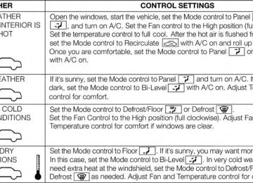
IF YOUR ENGINE OVERHEATS In any of the following situations, you can reduce the potential for overheating by taking the appropriate action. • On the highways — slow down. • In city traffic — while stopped, place the transmission in NEUTRAL, but do not increase the engine idle speed.
NOTE: There are steps that you can take to slow down an impending overheat condition: • If your air conditioner (A/C) is on, turn it off. The A/C system adds heat to the engine cooling system and turning the A/C off can help remove this heat. • You can also turn the temperature control to maximum heat, the mode control to floor and the blower control to high. This allows the heater core to act as a supplement to the radiator and aids in removing heat from the engine cooling system.
CAUTION!
WARNING!
WHAT TO DO IN EMERGENCIES 577
Driving with a hot cooling system could damage your vehicle. If the temperature gauge reads HOT (H), pull over and stop the vehicle. Idle the vehicle with the air conditioner turned off until the pointer drops back into the normal range. If the pointer remains on HOT (H), and you hear continuous chimes, turn the engine off immediately and call for service.
You or others can be badly burned by hot engine coolant (antifreeze) or steam from your radiator. If you see or hear steam coming from under the hood, do not open the hood until the radiator has had time to cool. Never try to open a cooling system pressure cap when the radiator or coolant bottle is hot.
JACKING AND TIRE CHANGING
WARNING!
• Do not attempt to change a tire on the side of the vehicle close to moving traffic. Pull far enough off the road to avoid the danger of being hit when operating the jack or changing the wheel.
(Continued)
578 WHAT TO DO IN EMERGENCIES
WARNING! (Continued)
• Being under a jacked-up vehicle is dangerous. The vehicle could slip off the jack and fall on you. You could be crushed. Never put any part of your body under a vehicle that is on a jack. If you need to get under a raised vehicle, take it to a service center where it can be raised on a lift. • Never start or run the engine while the vehicle is on a jack. • The jack is designed to be used as a tool for changing tires only. The jack should not be used to lift the vehicle for service purposes. The vehicle should be jacked on a firm level surface only. Avoid ice or slippery areas.
Jack Location The scissor-type jack and tire changing tools are located in rear cargo area, below the load floor.
Jack Storage Location
Rotate the plastic thumb screw on the end of the jack to loosen the jack and remove from the bracket.
WHAT TO DO IN EMERGENCIES 579
the square socket extension to rotate the “spare tire drive” nut. The nut is located under a plastic cover at the center-rear of the cargo floor area, just inside the liftgate opening.Thumb Screw Location
Spare Tire Stowage The spare tire is stowed under the rear of the vehicle by means of a cable winch mechanism. To remove or stow the spare, use the jack handle/lug wrench connected to
Spare Tire Location
580 WHAT TO DO IN EMERGENCIES
CAUTION!
Do not use power tools to winch the tire up or down. Impact type tools can damage the winch mechanism.
Spare Tire Removal
1. Remove the jack tools from the bag. 2. Raise the rubber mat and remove the plug from
storage compartment floor.
3. Fit the jack handle extension over the drive nut. Use the lug wrench handle and extension to completely lower the spare tire. Keep turning the handle until the winch stops.
Lowering/Raising Spare Tire
4. Slide the tire out from under the vehicle and rotate it
vertically behind the rear bumper.
WHAT TO DO IN EMERGENCIES 581
Spare Tire
Tab Location
5. Spread the retaining tabs on the plastic plate and pull the metal stamping toward you to release it from the plastic plate.
582 WHAT TO DO IN EMERGENCIES 6. Slide the metal stamping up the steel extension tube and winch cable. Rotate the metal stamping and push it through the hole in the plastic plate and wheel.
Sleeve And Cable
7. Pinch the three short and two long tubes to remove the
protective plate from the steel spare wheel.
Releasing Protective Plate
Preparations For Jacking
1. Park the vehicle on a firm level surface, away from
traffic.
WARNING!
Jacking Instructions
WHAT TO DO IN EMERGENCIES 583
Do not attempt to change a tire on the side of the vehicle closest to moving traffic, pull far enough off the road to avoid being hit when operating the jack or changing the wheel.
2. Place the transmission in PARK, set the parking brake
and activate the Hazard Warning flashers.
3. Block the diagonally opposite wheel.
NOTE: Passengers should not remain in the vehicle when the vehicle is being jacked.
WARNING!
Carefully follow these tire changing warnings to help prevent personal injury or damage to your vehicle: • Always park on a firm, level surface as far from the edge of the roadway as possible before raising the vehicle. • Turn on the Hazard Warning flasher. • Block the wheel diagonally opposite the wheel to be raised. • Set the parking brake firmly and set the automatic transmission in PARK. • Never start or run the engine with the vehicle on a jack.
(Continued)
584 WHAT TO DO IN EMERGENCIES
WARNING! (Continued)
• Do not let anyone sit in the vehicle when it is on a jack. • Do not get under the vehicle when it is on a jack. If you need to get under a raised vehicle, take it to a service center where it can be raised on a lift. • Only use the jack in the positions indicated and for lifting this vehicle during a tire change. • If working on or near a roadway, be extremely careful of motor traffic. • To assure that spare tires, flat or inflated, are securely stowed, spares must be stowed with the valve stem facing the ground.
Jack Warning Label
CAUTION!
Do not attempt to raise the vehicle by jacking on locations other than those indicated in the Jacking Instructions for this vehicle.
1. Loosen (but do not remove) the wheel lug nuts by turning them to the left, one turn, while the wheel is still on the ground.
2. Assemble the jack and jacking tools.
WHAT TO DO IN EMERGENCIES 585
Jack And Tool Assembly
Lift Point Symbol On Sill Molding
3. For the front axle, place the jack on the body flange just behind the front tire as indicated by the triangular lift point symbol on the sill molding. Do not raise the vehicle until you are sure the jack is fully engaged.
586 WHAT TO DO IN EMERGENCIES
Front Jack Location
Lift Point On Sill Molding
4. For a rear tire, place the jack in the slot on the rear tie-down bracket, just forward of the rear tire (as indicated by the triangular lift point symbol on the sill molding). Do not raise the vehicle until you are sure the jack is fully engaged.
WHAT TO DO IN EMERGENCIES 587
WARNING!
Raising the vehicle higher than necessary can make the vehicle less stable. It could slip off the jack and hurt someone near it. Raise the vehicle only enough to remove the tire.
6. Remove the lug nuts and wheel. 7. Install the spare wheel/tire on the vehicle and install the lug nuts with the cone-shaped end toward the wheel. Lightly tighten the nuts.
Rear Jacking Location
5. Raise the vehicle by turning the jack screw clockwise. Raise the vehicle just enough to remove the flat tire.
588 WHAT TO DO IN EMERGENCIES
CAUTION!
WARNING!
Be sure to mount the spare tire with the valve stem facing outward. The vehicle could be damaged if the spare tire is mounted incorrectly.
To avoid the risk of forcing the vehicle off the jack, do not fully tighten the lug nuts until the vehicle has been lowered. Failure to follow this warning may result in personal injury.
8. Lower the vehicle by turning the jack screw counter-
clockwise, and remove the jack and wheel blocks.
9. Finish tightening the lug nuts. Push down on the wrench while at the end of the handle for increased leverage. Tighten the lug nuts in a star pattern until each nut has been tightened twice. The correct wheel nut tightness is 110 ft lbs (150 N·m). If in doubt about the correct tightness, have them checked with a torque wrench by your authorized dealer or at a service station.
Mounting Spare Tire
10. Push out the small center cap using the jack tool from inside the aluminum road wheel and position the wheel behind the rear bumper with the “beauty side” facing rearward.
WHAT TO DO IN EMERGENCIES 589
11. Insert the two long tubes on the plastic protective plate in the lug holes of the road wheel. Push the end of the winch’s cable, spring, steel sleeve and stamped cone shape wheel plate though the road wheel and protective plate.“Beauty Side”
NOTE: The plastic plate will prevent the road wheel from being scratched when sliding it under the vehicle.
Installing Winch
590 WHAT TO DO IN EMERGENCIES 12. Slide the road wheel on the ground using the protec- tive plate until it is directly under the winch and between the rear bumper and exhaust system heat shields. Raise the tire by turn the lug wrench on the winch extension clockwise until it clicks/ratchets three times to make sure the cable is tight.
Road Wheel Installed In Spare Location
NOTE: Double check to ensure the tire is snug against the underbody of the vehicle. Damage to the winch cable may result if the vehicle is driven with the tire loose.
WARNING!
Do not use power tools to winch the tire up or down. Impact-type tools may damage the winch mecha- nism.
13. Lower the jack to the fully closed position. Return the tools to the proper positions in the tool bag. Fold the flap on the tool bag under the tools and roll the tools in the bag underneath the others. Use the Velcro straps to secure the tool bag to the jack with the lug wrench on the forward side of the jack. Expand the jack on the bracket by turning the thumb screw clockwise until it is tight to prevent rattles.
14. Reinstall the plastic plug into the floor of the cargo area. Roll up and store the Jack, Tool Kit and Tire Changing Instructions. Reinstall the cover for the jack in the rear storage bin.
15. Have the aluminum road wheel and tire repaired as soon as possible and properly secure the spare tire, jack and tool kit.
WARNING!
A loose tire or jack thrown forward in a collision or hard stop could endanger the occupants of the ve- hicle. Always stow the jack parts and the spare tire in the places provided.
WHAT TO DO IN EMERGENCIES 591
Road Tire Installation
1. Mount the road tire on the axle. 2. Install the remaining lug nuts with the cone shaped end of the nut toward the wheel. Lightly tighten the lug nuts.
WARNING!
To avoid the risk of forcing the vehicle off the jack, do not tighten the lug nuts fully until the vehicle has been lowered. Failure to follow this warning may result in personal injury.
3. Lower the vehicle to the ground by turning the jack
handle counterclockwise.
592 WHAT TO DO IN EMERGENCIES 4. Finish tightening the lug nuts. Push down on the wrench while at the end of the handle for increased leverage. Tighten the lug nuts in a star pattern until each nut has been tightened twice. The correct tight- ness of each lug nut is 110 ft-lbs (150 N·m). If in doubt about the correct tightness, have them checked with a torque wrench by your authorized dealer or service station.
5. After 25 miles (40 km) check the lug nut torque with a torque wrench to ensure that all lug nuts are properly seated against the wheel.
JUMP-STARTING If your vehicle has a discharged battery it can be jump- started using a set of jumper cables and a battery in another vehicle or by using a portable battery booster pack. Jump-starting can be dangerous if done improperly so please follow the procedures in this section carefully.
NOTE: When using a portable battery booster pack follow the manufacturer’s operating instructions and precautions.
CAUTION!
Do not use a portable battery booster pack or any other booster source with a system voltage greater than 12 Volts or damage to the battery, starter motor, alternator or electrical system may occur.
WARNING!
Do not attempt jump-starting if the battery is frozen. It could rupture or explode and cause personal injury.
Preparations For Jump-Start The battery in your vehicle is located under the passen- ger’s front seat. There are remote locations located under the hood to assist in jump-starting.
WHAT TO DO IN EMERGENCIES 593
WARNING!
• Take care to avoid the radiator cooling fan when- ever the hood is raised. It can start anytime the ignition switch is ON. You can be injured by moving fan blades. • Remove any metal jewelry such as watch bands or bracelets that might make an inadvertent electrical contact. You could be seriously injured. • Batteries contain sulfuric acid that can burn your skin or eyes and generate hydrogen gas which is flammable and explosive. Keep open flames or sparks away from the battery.
1. Set the parking brake, shift the automatic transmission
into PARK and turn the ignition to LOCK.
2. Turn off the heater, radio, and all unnecessary electri-
cal accessories.
Remote Battery Posts
1 — Remote Positive (+) Post (covered with protective cap) 2 — Remote Negative (-) Post
594 WHAT TO DO IN EMERGENCIES 3. Remove the protective cover over the remote posi- tive (+) battery post. Pull upward on the cover to remove it.
4. If using another vehicle to jump-start the battery, park the vehicle within the jumper cables reach, set the parking brake and make sure the ignition is OFF.
WARNING!
Do not allow vehicles to touch each other as this could establish a ground connection and personal injury could result.
Jump-Starting Procedure
WARNING!
Failure to follow this procedure could result in per- sonal injury or property damage due to battery ex- plosion.
CAUTION!
Failure to follow these procedures could result in damage to the charging system of the booster vehicle or the discharged vehicle.
1. Connect the positive (+) end of the jumper cable to the
remote positive (+) post of the discharged vehicle.
2. Connect the opposite end of the positive (+) jumper
cable to the positive (+) post of the booster battery.
3. Connect the negative end (-) of the jumper cable to the
negative (-) post of the booster battery.
4. Connect the opposite end of the negative (-) jumper cable to the remote negative (-) post of the vehicle with the discharged battery.
WARNING!
Do not connect the cable to the negative post (-) of the discharged battery. The resulting electrical spark could cause the battery to explode and could result in personal injury.
5. Start the engine in the vehicle that has the booster battery, let the engine idle a few minutes, and then start the engine in the vehicle with the discharged battery.
WHAT TO DO IN EMERGENCIES 595
Once the engine is started, remove the jumper cables in the reverse sequence: 6. Disconnect the negative (-) jumper cable from theremote negative (-) post of the discharged vehicle.
7. Disconnect the negative end (-) of the jumper cable
from the negative (-) post of the booster battery.
8. Disconnect the opposite end of the positive (+) jumper cable from the positive (+) post of the booster battery. 9. Disconnect the positive (+) end of the jumper cable from the remote positive (+) post of the discharged vehicle.
10. Reinstall the protective cover over the remote posi-
tive (+) battery post of the discharged vehicle.
If frequent jump-starting is required to start your vehicle you should have the battery and charging system in- spected at your authorized dealer.
596 WHAT TO DO IN EMERGENCIES
CAUTION!
Accessories that can be plugged into the vehicle power outlets draw power from the vehicle’s battery, even when not in use (i.e., cellular phones, etc.). Eventually, if plugged in long enough, the vehicle’s battery will discharge sufficiently to degrade battery life and/or prevent the engine from starting.
FREEING A STUCK VEHICLE If your vehicle becomes stuck in mud, sand or snow, it can often be moved using a rocking motion. Turn the steering wheel right and left to clear the area around the front wheels. Press and hold the lock button on the shift lever. Then shift back and forth between DRIVE and REVERSE while gently pressing the accelerator.
NOTE: Shifts between DRIVE and REVERSE can only be achieved at wheel speeds of 5 mph or less. Whenever the transmission remains in NEUTRAL for more than 2 sec- onds, you must press the brake pedal to engage DRIVE or REVERSE. Use the least amount of accelerator pedal pressure that will maintain the rocking motion without spinning the wheels or racing the engine. NOTE: Press the ⬙ESC Off⬙ switch (if necessary), to place the Electronic Stability Control (ESC) system in ⬙Partial Off⬙ mode, before rocking the vehicle. Refer to “Elec- tronic Brake Control” in “Starting And Operating” for further information. Once the vehicle has been freed, press the ⬙ESC Off⬙ switch again to restore ⬙ESC On⬙ mode.
CAUTION!
Racing the engine or spinning the wheels may lead to transmission overheating and failure. Allow the en- gine to idle with the transmission in NEUTRAL for at least one minute after every five rocking-motion cycles. This will minimize overheating and reduce the risk of transmission failure during prolonged efforts to free a stuck vehicle.
CAUTION!
• When “rocking” a stuck vehicle by shifting between DRIVE and REVERSE, do not spin the wheels faster than 15 mph (24 km/h), or drivetrain damage may result.
(Continued)
WHAT TO DO IN EMERGENCIES 597
CAUTION! (Continued)
• Revving the engine or spinning the wheels too fast may lead to transmission overheating and failure. It can also damage the tires. Do not spin the wheels above 30 mph (48 km/h) while in gear (no trans- mission shifting occurring).
WARNING!
Fast spinning tires can be dangerous. Forces gener- ated by excessive wheel speeds may cause damage, or even failure, of the axle and tires. A tire could explode and injure someone. Do not spin your vehi- cle’s wheels faster than 30 mph (48 km/h) or for longer than 30 seconds continuously without stop- ping when you are stuck and do not let anyone near a spinning wheel, no matter what the speed.
598 WHAT TO DO IN EMERGENCIES EMERGENCY TOW HOOKS — IF EQUIPPED If your vehicle is equipped with tow hooks, there will be one in the rear and two mounted on the front of the vehicle. The rear hook will be located on the driver’s side of the vehicle. NOTE: For off-road recovery, it is recommended to use both of the front tow hooks to minimize the risk of damage to the vehicle.
WARNING!
• Do not use a chain for freeing a stuck vehicle. Chains may break, causing serious injury or death. • Stand clear of vehicles when pulling with tow hooks. Tow straps may become disengaged, caus- ing serious injury.
CAUTION!
Tow hooks are for emergency use only, to rescue a vehicle stranded off road. Do not use tow hooks for tow truck hookup or highway towing. You could damage your vehicle.
SHIFT LEVER OVERRIDE If a malfunction occurs and the shift lever cannot be moved out of the PARK position, you can use the following procedure to temporarily move the shift lever: 1. Turn the engine OFF. 2. Firmly apply the parking brake. 3. Remove the rubber liner from the cupholder (located
next to the shifter on the center console).
4. Using a small screwdriver or similar tool, remove the shift lever override access cover (located on the bot- tom of the cupholder).
Shift Lever Override Access Cover
WHAT TO DO IN EMERGENCIES 599
5. Press and maintain firm pressure on the brake pedal. 6. Insert the screwdriver or similar tool into the access hole, and push and hold the override release lever down.
7. Move the shift lever to the NEUTRAL position. 8. The vehicle may then be started in NEUTRAL. 9. Reinstall the shift lever override access cover and
cupholder liner.
TOWING A DISABLED VEHICLE This section describes procedures for towing a disabled vehicle using a commercial wrecker service. If the trans- mission and drivetrain are operable, disabled vehicles may also be towed as described under “Recreational Towing” in the “Starting and Operating” section.
600 WHAT TO DO IN EMERGENCIES
Towing Condition Flat Tow
Wheels OFF the Ground
NONE
RWD MODELS
AWD MODELS
If transmission is operable: • Transmission in NEUTRAL • 30 mph (48 km/h) • 15 miles (24 km) max
max speed
distance
See instructions in “Recreational
Towing” under “Starting and
Operating” • Transmission in PARK • Transfer Case in NEUTRAL • Tow in forward direction NOT ALLOWED NOT ALLOWED BEST METHOD
Wheel Lift or
Dolly Tow
Flatbed
Front Rear ALL
OK
BEST METHOD
Proper towing or lifting equipment is required to prevent damage to your vehicle. Use only tow bars and other equipment designed for this purpose, following equip- ment manufacturer’s instructions. Use of safety chains is mandatory. Attach a tow bar or other towing device to
main structural members of the vehicle, not to bumpers or associated brackets. State and local laws regarding vehicles under tow must be observed. If you must use the accessories (wipers, defrosters, etc.) while being towed, the ignition must be in the ON/RUN position, not the ACC position.
If the key fob is unavailable or the battery is discharged, refer to “Shift Lever Override” in “What To Do In Emergencies” for instructions on shifting the automatic transmission out of PARK for towing.
CAUTION!
Do not use sling type equipment when towing. When securing the vehicle to a flat bed truck, do not attach to front or rear suspension components. Dam- age to your vehicle may result from improper towing.
Without The Key Fob Special care must be taken when the vehicle is towed with the ignition in the LOCK/OFF position. The only approved method of towing without the key fob is with a flatbed truck. Proper towing equipment is necessary to prevent damage to the vehicle.
WHAT TO DO IN EMERGENCIES 601
Rear-Wheel Drive Models The manufacturer recommends towing your vehicle with all four wheels OFF the ground using a flatbed. If flatbed equipment is not available, and the transmis- sion is operable, the vehicle may be towed (with rear wheels on the ground) with the transmission in NEU- TRAL. Speed must not exceed 30 mph (48 km/h) and the distance must not exceed 15 miles (24 km).
CAUTION!
Towing faster than 30 mph (48 km/h) or farther than 15 mi (24 km) with rear wheels on the ground can cause severe engine or transmission damage. Such damage is not covered by the New Vehicle Limited Warranty.
602 WHAT TO DO IN EMERGENCIES If the transmission is not operable, or the vehicle must be towed faster than 30 mph (48 km/h) or farther than 15 miles (24 km), tow with the rear wheels OFF the ground. Acceptable methods are to tow the vehicle on a flatbed, or with the front wheels raised and the rear wheels on a towing dolly, or (when using a suitable steering wheel stabilizer to hold the front wheels in the straight position) with the rear wheels raised and the front wheels on the ground. All-Wheel Drive Models The manufacturer recommends towing with all wheels OFF the ground. Acceptable methods are to tow the vehicle on a flatbed or with one end of vehicle raised and the opposite end on a towing dolly. If flatbed equipment is not available, and the transfer case is operable, the vehicles with a two-speed transfer case may be towed (in the forward direction, with ALL wheels on the ground), IF the transfer case is in NEUTRAL and the
transmission is in PARK. Refer to “Recreational Towing” in “Starting and Operating” for detailed instructions. Vehicles equipped with a single-speed transfer case have no NEUTRAL position, and therefore must be towed will all four wheels OFF the ground.
CAUTION!
• Front or rear wheel lifts must not be used. Internal damage to the transmission or transfer case will occur if a front or rear wheel lift is used when towing. • Towing this vehicle in violation of the above re- quirements can cause severe transmission and/or transfer case damage. Damage from improper tow- ing is not covered under the New Vehicle Limited Warranty.
MAINTAINING YOUR VEHICLE
CONTENTS 䡵 ENGINE COMPARTMENT — 3.6L . . . . . . . . ..605
䡵 ENGINE COMPARTMENT — 5.7L . . . . . . . . ..606
䡵 ONBOARD DIAGNOSTIC SYSTEM (OBD II) . . .607
▫ Loose Fuel Filler Cap Message . . . . . . . . . . ..607
䡵 EMISSIONS INSPECTION AND MAINTENANCEPROGRAMS . . . . . . . . . . . . . . . . . . . . . . . . . .608
䡵 REPLACEMENT PARTS . . . . . . . . . . . . . . . . ..609
䡵 DEALER SERVICE . . . . . . . . . . . . . . . . . . . . . .610
䡵 MAINTENANCE PROCEDURES . . . . . . . . . ..610
. . . . . . . . . . . . . . . . . . . . . . . . . .611▫ Engine Oil
▫ Engine Oil Filter . . . . . . . . . . . . . . . . . . . . . .614
▫ Engine Air Cleaner Filter . . . . . . . . . . . . . . ..614
▫ Maintenance-Free Battery . . . . . . . . . . . . . ..615
▫ Air Conditioner Maintenance . . . . . . . . . . . ..616
▫ Body Lubrication . . . . . . . . . . . . . . . . . . . ..619
▫ Windshield Wiper Blades . . . . . . . . . . . . . ..619
▫ Adding Washer Fluid . . . . . . . . . . . . . . . . ..621
▫ Exhaust System . . . . . . . . . . . . . . . . . . . . . .622
▫ Cooling System . . . . . . . . . . . . . . . . . . . . . .625
▫ Brake System . . . . . . . . . . . . . . . . . . . . . . . .630604 MAINTAINING YOUR VEHICLE
▫ Front/Rear Axle Fluid . . . . . . . . . . . . . . . . ..632
▫ Transfer Case . . . . . . . . . . . . . . . . . . . . . . . .633
▫ Automatic Transmission . . . . . . . . . . . . . . ..634
▫ Appearance Care And ProtectionFrom Corrosion . . . . . . . . . . . . . . . . . . . . . .638
䡵 FUSES . . . . . . . . . . . . . . . . . . . . . . . . . . . . . .643
▫ Totally Integrated Power Module . . . . . . . . ..643
䡵 VEHICLE STORAGE . . . . . . . . . . . . . . . . . . ..650
䡵 REPLACEMENT BULBS . . . . . . . . . . . . . . . ..650
䡵 BULB REPLACEMENT . . . . . . . . . . . . . . . . ..651▫ High Intensity Discharge Headlamps (HID) – If
Equipped . . . . . . . . . . . . . . . . . . . . . . . . . . .651
▫ Halogen Headlamps – If Equipped . . . . . . . ..652▫ Front Turn Signal . . . . . . . . . . . . . . . . . . . ..652
▫ Front Fog Lamps . . . . . . . . . . . . . . . . . . . ..652
▫ Rear Tail, Stop, Turn Signal,And Backup Lamps
. . . . . . . . . . . . . . . . . ..653
▫ Rear Liftgate Mounted Tail Lamp . . . . . . . . ..654
▫ Center High-Mounted Stop Lamp (CHMSL) . .655
▫ Rear License Lamp . . . . . . . . . . . . . . . . . . ..655
䡵 FLUID CAPACITIES . . . . . . . . . . . . . . . . . . ..656
䡵 FLUIDS, LUBRICANTS ANDGENUINE PARTS . . . . . . . . . . . . . . . . . . . . . .657
▫ Engine . . . . . . . . . . . . . . . . . . . . . . . . . . . . .657
▫ Chassis . . . . . . . . . . . . . . . . . . . . . . . . . . . . .658ENGINE COMPARTMENT — 3.6L
MAINTAINING YOUR VEHICLE 605
1 — Totally Integrated Power Module (Fuses) 2 — Engine Oil Dipstick 3 — Engine Oil Fill 4 — Brake Fluid Reservoir 5 — Power Steering Fluid Reservoir
6 — Air Cleaner Filter 7 — Washer Fluid Reservoir 8 — Coolant Pressure Cap (Radiator) 9 — Engine Coolant Reservoir
606 MAINTAINING YOUR VEHICLE ENGINE COMPARTMENT — 5.7L
1 — Totally Integrated Power Module (Fuses) 2 — Automatic Transmission Dipstick 3 — Engine Oil Fill 4 — Brake Fluid Reservoir 5 — Air Cleaner Filter
6 — Washer Fluid Reservoir 7 — Engine Oil Dipstick 8 — Coolant Pressure Cap (Radiator) 9 — Engine Coolant Reservoir
ONBOARD DIAGNOSTIC SYSTEM (OBD II) Your vehicle is equipped with a sophisticated onboard diagnostic system called OBD II. This system monitors the performance of the emissions, engine, and automatic transmission control systems. When these systems are operating properly, your vehicle will provide excellent performance and fuel economy, as well as engine emis- sions well within current government regulations. If any of these systems require service, the OBD II system will turn on the “Malfunction Indicator Light (MIL).” It will also store diagnostic codes and other information to assist your service technician in making repairs. Al- though your vehicle will usually be drivable and not need towing, see your authorized dealer for service as soon as possible.
MAINTAINING YOUR VEHICLE 607
CAUTION!
• Prolonged driving with the MIL on could cause further damage to the emission control system. It could also affect fuel economy and drivability. The vehicle must be serviced before any emissions tests can be performed. • If the MIL is flashing, while the engine is running, severe catalytic converter damage and power loss will soon occur. Immediate service is required.
Loose Fuel Filler Cap Message
If the vehicle diagnostic system determines that the fuel filler cap is loose, improperly installed, or damaged, a loose gascap indicator will display in the EVIC telltale display area. Refer to “Electronic Vehicle Information Center (EVIC) in “Understanding Your Instrument Panel” for further in- formation. Tighten the fuel filler cap properly and press
608 MAINTAINING YOUR VEHICLE the SELECT button to turn off the message. If the problem continues, the message will appear the next time the vehicle is started. A loose, improperly installed, or damaged fuel filler cap may also turn on the Malfunction Indicator Light (MIL).
EMISSIONS INSPECTION AND MAINTENANCE PROGRAMS In some localities, it may be a legal requirement to pass an inspection of your vehicle’s emissions control system. Failure to pass could prevent vehicle registration.
For states that require an Inspection and Mainte- nance (I/M), this check verifies the “Malfunction Indicator Light (MIL)” is functioning and is not on when the engine is running, and that the OBD II system is ready for testing.
Normally, the OBD II system will be ready. The OBD II system may not be ready if your vehicle was recently serviced, recently had a dead battery or a battery replace- ment. If the OBD II system should be determined not ready for the I/M test, your vehicle may fail the test. Your vehicle has a simple ignition key-actuated test, which you can use prior to going to the test station. To check if your vehicle’s OBD II system is ready, you must do the following: 1. Turn the ignition switch to the ON position, but do not
crank or start the engine.
2. If you crank or start the engine, you will have to start
this test over.
3. As soon as you turn the ignition switch to the ON position, you will see the MIL symbol come on as part of a normal bulb check.
happen:
4. Approximately 15 seconds later, one of two things will • The MIL will flash for about 10 seconds and then return to being fully illuminated until you turn OFF the ignition or start the engine. This means that your vehicle’s OBD II system is not ready and you should not proceed to the I/M station. • The MIL will not flash at all and will remain fully illuminated until you turn OFF the ignition or start the engine. This means that your vehicle’s OBD II system is ready and you can proceed to the I/M station.
If your OBD II system is not ready, you should see your authorized dealer or repair facility. If your vehicle was recently serviced or had a battery failure or replacement, you may need to do nothing more than drive your
MAINTAINING YOUR VEHICLE 609
vehicle as you normally would in order for your OBD II system to update. A recheck with the above test routine may then indicate that the system is now ready. Regardless of whether your vehicle’s OBD II system is ready or not, if the MIL is illuminated during normal vehicle operation you should have your vehicle serviced before going to the I/M station. The I/M station can fail your vehicle because the MIL is on with the engine running.REPLACEMENT PARTS Use of genuine MOPAR® parts for normal/scheduled maintenance and repairs is highly recommended to en- sure the designed performance. Damage or failures caused by the use of non-MOPAR® parts for mainte- nance and repairs will not be covered by the manufac- turer’s warranty.
610 MAINTAINING YOUR VEHICLE DEALER SERVICE Your authorized dealer has the qualified service person- nel, special tools, and equipment to perform all service operations in an expert manner. Service Manuals are available which include detailed service information for your vehicle. Refer to these Service Manuals before attempting any procedure yourself. NOTE: Intentional tampering with emissions control systems may void your warranty and could result in civil penalties being assessed against you.
WARNING!
You can be badly injured working on or around a motor vehicle. Only do service work for which you have the knowledge and the proper equipment. If you have any doubt about your ability to perform a service job, take your vehicle to a competent mechanic.
MAINTENANCE PROCEDURES The pages that follow contain the required maintenance services determined by the engineers who designed your vehicle. Besides those maintenance items specified in the fixed maintenance schedule, there are other components which may require servicing or replacement in the future.
CAUTION!
• Failure to properly maintain your vehicle or per- form repairs and service when necessary could result in more costly repairs, damage to other components or negatively impact vehicle perfor- mance. Immediately have potential malfunctions examined by an authorized dealer or qualified repair center.
(Continued)
CAUTION! (Continued)
• Your vehicle has been built with improved fluids that protect the performance and durability of your vehicle and also allow extended maintenance inter- vals. Do not use chemical flushes in these compo- nents as the chemicals can damage your engine, transmission, power steering or air conditioning. Such damage is not covered by the New Vehicle Limited Warranty. If a flush is needed because of component malfunction, use only the specified fluid for the flushing procedure.
Engine Oil
Checking Oil Level To assure proper engine lubrication, the engine oil must be maintained at the correct level. Check the oil level at regular intervals, such as every fuel stop. The best time to
MAINTAINING YOUR VEHICLE 611
check the engine oil level is about five minutes after a fully warmed engine is shut off, or before starting the engine after it has sat overnight. Checking the oil while the vehicle is on level ground will improve the accuracy of the oil level readings. Maintain the oil level in the SAFE level range. Adding 1 U.S. Quart (0.95L) of oil when the level is at the bottom of the SAFE range will result in the level being at the top of the SAFE range.CAUTION!
Overfilling or underfilling the crankcase will cause aeration or loss of oil pressure. This could damage your engine.
612 MAINTAINING YOUR VEHICLE Change Engine Oil The oil change indicator system will remind you that it is time to take your vehicle in for scheduled maintenance. Refer to the “Maintenance Schedule” for further informa- tion. NOTE:Under no circumstances should oil change inter- vals exceed 10,000 miles (16,000 km) or twelve months, whichever occurs first.
Engine Oil Selection For best performance and maximum protection under all types of operating conditions, the manufacturer only recommends engine oils that are API Certified and meet the requirements of Chrysler Material Standard MS-6395.
American Petroleum Institute (API) Engine Oil Identification Symbol
This symbol means that the oil has been certified by the American Pe- troleum Institute (API). The manu- facturer only recommends API Cer- tified engine oils.
CAUTION!
Do not use chemical flushes in your engine oil as the chemicals can damage your engine. Such damage is not covered by the New Vehicle Limited Warranty.
Engine Oil Viscosity – 3.6L Engine SAE 5W-20 engine oil is recommended for all operating temperatures. This engine oil improves low temperature starting and vehicle fuel economy. The engine oil filler cap also shows the recommended engine oil viscosity for your engine. For information on engine oil filler cap location, refer to the “Engine Com- partment” illustration in this section. Engine Oil Viscosity – 5.7L Engine SAE 5W-20 engine oil is recommended for all operating temperatures. This engine oil improves low temperature starting and vehicle fuel economy. The engine oil filler cap also shows the recommended engine oil viscosity for your engine. For information on engine oil filler cap location, refer to “Engine Compartment” in “Main- taining Your Vehicle” for further information.
MAINTAINING YOUR VEHICLE 613
NOTE: Vehicles equipped with a 5.7L engine must use SAE 5W-20 oil. Failure to do so may result in improper operation of the Fuel Saver Technology. Refer to “Fuel Saver Technology – If Equipped” in “Starting and Oper- ating” for further information. Lubricants that do not have both, the engine oil certifi- cation mark and the correct SAE viscosity grade number should not be used. Materials Added To Engine Oil The manufacturer strongly recommends against the addi- tion of any additives (other than leak detection dyes) to the engine oil. Engine oil is an engineered product and its performance may be impaired by supplemental additives. Disposing Of Used Engine Oil And Oil Filters Care should be taken in disposing of used engine oil and oil filters from your vehicle. Used oil and oil filters, indiscriminately discarded, can present a problem to the