- 2011 Dodge Durango Owners Manuals
- Dodge Durango Owners Manuals
- 2008 Dodge Durango Owners Manuals
- Dodge Durango Owners Manuals
- 2009 Dodge Durango Owners Manuals
- Dodge Durango Owners Manuals
- 2007 Dodge Durango Owners Manuals
- Dodge Durango Owners Manuals
- 2004 Dodge Durango Owners Manuals
- Dodge Durango Owners Manuals
- 2013 Dodge Durango Owners Manuals
- Dodge Durango Owners Manuals
- 2005 Dodge Durango Owners Manuals
- Dodge Durango Owners Manuals
- 2006 Dodge Durango Owners Manuals
- Dodge Durango Owners Manuals
- 2012 Dodge Durango Owners Manuals
- Dodge Durango Owners Manuals
- Download PDF Manual
-
section in your vehicle’s Owner’s Manual for more information. Ensure the Remote Control and Headphone switch is on Channel 1. Using The Remote Control 1. Press the MODE button on the Remote Control. 2. While looking at the video screen, highlight VES AUX 1, by either pressing Up/Down/Left/Right buttons or by repeatedly pressing the MODE button, then press ENTER on the Remote Control.
UNDERSTANDING YOUR INSTRUMENT PANEL 393
Using The Touch-Screen Radio Controls 1. Press the MENU hard-key on the radio faceplate. 2. Touch the Rear VES soft-key to display the Rear VES Controls. If a channel list is displayed, press the HIDE LIST soft-key to display the Rear VES Controls screen.
Select VES AUX1 Mode On The VES Screen
Rear VES Soft-Key
394 UNDERSTANDING YOUR INSTRUMENT PANEL 3. Touch the 1 soft-key and then touch AUX 1 in the VES column. To exit press the back arrow soft-key at the top of the screen.
Listen To An Audio Source On Channel 2 While A Video Is Playing On Channel 1
Ensure the Remote Control and Headphone switch is on Channel 2. Using The Remote Control 1. Press the MODE/SOURCE button on the Remote Control and the Mode Select Screen will display, unless a video is playing then only a small banner will appear on the bottom of the screen.Select Channel/Screen 1 And AUX 1 In The VES
Column
2. While looking at the video screen, either press Up/ Down/Left/Right on the Remote Control to highlight the desired audio source or repeatedly press the MODE/SOURCE button on the remote until the de- sired audio source appears on the screen.
UNDERSTANDING YOUR INSTRUMENT PANEL 395
Using The Touch-Screen Radio Controls 1. Press the MENU hard-key on the radio faceplate. 2. Touch the Rear VES soft-key to display the Rear VES Controls. If a channel list is displayed, press the HIDE LIST soft-key to display the Rear VES Controls screen.
Select FM Mode On The VES Screen
Rear VES Soft-Key
396 UNDERSTANDING YOUR INSTRUMENT PANEL 3. To listen to an audio source on Channel 2 while a video is playing on Channel 1, touch the 2 soft-key and choose an audio source. To exit touch the back arrow soft-key at the top left of the left screen.
simultaneously.
and right side equates to Channel 2.
Important Notes For Single Video Screen System • VES™ is able to transmit two channels of stereo audio • In split screen mode the left side equates to Channel 1
• If a video source is selected on Channel 1, then Channel 2 is for audio only. Selecting a video source (DVD) will not show the video on the screen. • When selecting a video source on Channel 1, the video will display on the screen and the audio could be heard on Channel 1 in the headphones. • Audio can be heard through the headphones evenwhen the Video Screen is closed.
Select Channel/Screen 2 And HDD In The Media
Play A DVD Using The Touch-Screen Radio
Column
1. Press the OPEN/CLOSE or LOAD hard-key on the
radio faceplate (Touch-Screen).
2. Insert the DVD with the label facing up. The radio automatically selects the appropriate mode after the disc is recognized and displays the menu screen or starts playing the first track.
3. To watch a DVD on Screen 1 for second row passen- gers, ensure the Remote Control and Headphone switch is on Channel 1.
Using The Remote Control 1. Press the MODE button on the Remote Control. 2. While looking at Screen 1, highlight DISC by either pressing Up/Down/Left/Right buttons or by repeat- edly pressing the MODE button, then press ENTER. NOTE:
UNDERSTANDING YOUR INSTRUMENT PANEL 397
Select DISC Mode On The VES Screen
• Channel/Screen 1 select mode information is shown • Channel/Screen 2 select mode information is shown
on the left side of the screen.
on the right side of the screen.
398 UNDERSTANDING YOUR INSTRUMENT PANEL Using The Touch-Screen Radio Controls 1. Press the MENU hard-key on the radio faceplate. 2. Touch the Rear VES soft-key to display the Rear VES Controls. If a channel list is displayed, press the HIDE LIST soft-key to display the Rear VES Controls screen.
Rear VES Soft-key
3. Touch the 1 or 2 soft-key and then the DISC soft-key in the MEDIA column. To exit touch the back arrow at the top left of the screen.
NOTE: • To view a DVD on the radio press the RADIO/MEDIA hard-key, on the radio faceplate, then touch the DISC tab soft-key and then the VIEW VIDEO soft-key. • Viewing a DVD on the Touch-Screen radio screen is not available in all states/provinces, and the vehicle must be stopped, and the shift lever must be in the PARK position for vehicles with automatic transmission. In vehicles with manual transmission the parking brake must be engaged. • Touching the screen on a Touch-Screen radio while a DVD is playing brings up basic remote control functions for DVD play such as scene selection, Play, Pause, FF, RW, and Stop. Pressing the X in the upper corner will turn off the remote control screen functions.
VES Remote Control – If Equipped
Remote Control
UNDERSTANDING YOUR INSTRUMENT PANEL 399
Controls And Indicators 1. Power – Turns the screen and wireless headphone transmitter for the selected Channel on or off. To hear audio while the screen is closed, press the Power button to turn the headphone transmitter on.
2. Channel Selector Indicators – When a button is pressed, the currently affected channel or channel button is illuminated momentarily.
3. Light – Turns the remote control backlighting on or off. The remote backlighting turns off automatically after five seconds.
400 UNDERSTANDING YOUR INSTRUMENT PANEL 4. Channel/Screen Selector Switch - Indicates which chan- nel is being controlled by the remote control. When the selector switch is in the Channel 1 position, the remote controls the functionality of screen Channel 1 (right side of the screen). When the selector switch is in the Channel 2, position the remote controls the functional- ity of screen Channel 2 (left side of the screen).
5. 䉴䉴 – In radio modes, press to seek the next tunable station. In disc modes, press and hold to fast forward through the current audio track or video chapter. In satellite video mode, press to advance to the next channel. In menu modes use to navigate in the menu. 6. 䉲 / Prev – In radio modes, press to select to the previous station. In disc modes, press to advance to the start of the current or previous audio track or video chapter. In satellite video mode, press to ad- vance to the previous channel. In menu modes, use to navigate in the menu.
7. MENU – Press to return to the main menu of a DVD disc, to select a satellite audio or video channel from the Station list, or select playback modes (SCAN/ RANDOM for a CD).
8. 䉴 / 㥋 (Play/Pause) – Begin/resume or pause disc play. 9. ▪ (Stop) – Stops disc play. 10. PROG Up/Down – When listening to a radio mode, pressing PROG Up selects the next preset and press- ing PROG Down selects the previous preset stored in the radio. When listening to compressed audio on a data disc, PROG Up selects the next directory and PROG Down selects the previous directory. When listening to a disc in a radio with a multiple-disc changer, PROG Up selects the next disc and PROG Down selects the previous disc.
11. MUTE – Press to mute the headphone audio output
for the selected channel.
12. SLOW – Press to slow playback of a DVD disc. Press
play (䉴) to resume normal play.
13. STATUS – Press to display the current status. 14. MODE – Press to change the mode of the selected this
channel. See the Mode Selection section of manual for details on changing modes.
15. SETUP – When in a video mode, press the SETUP button to access the display settings (see the display settings section) or the DVD Setup menu. When a disc is loaded in the DVD player (if equipped) and the VES™ mode is selected and the disc is stopped, press the SETUP button to access the DVD Setup menu. (see the DVD Setup Menu of this manual.)
16. BACK – When navigating in menu mode, press to return to the previous screen. When navigating a DVDs disc menu, the operation depends on the disc’s contents.
UNDERSTANDING YOUR INSTRUMENT PANEL 401
17. 䉳䉳 – In radio modes, press to seek to the previous tunable station. In disc modes, press and hold to fast rewind through the current audio track or video chapter. In satellite video mode, press to advance to the previous channel. In menu modes use to navigate in the menu.18. ENTER – Press to select the highlighted option in a
menu.
19. 䉱 / NEXT – In radio modes, press to select to the next station. In disc modes, press to advance to the next audio track or video chapter. In satellite video mode, press to advance to the next channel. In menu modes, use to navigate in the menu.
402 UNDERSTANDING YOUR INSTRUMENT PANEL Remote Control Storage The video screen(s) come with a built in storage compart- ment for the remote control which is accessible when the screen is opened. To remove the remote, use your index finger to pull and rotate the remote towards you. Do not try to pull the remote straight down as it will be very difficult to remove. To return the remote back into its storage area, insert one long edge of the remote into the two retaining clips first, and then rotate the remote back up into the other two retaining clips until it snaps back into position.
The Remote Control Storage
Locking The Remote Control All remote control functionality can be disabled as a parental control feature. • To disable the Remote Control from making any changes, press the Video Lock button on the DVD player (if equipped). If the vehicle is not equipped with a DVD player, follow the radio’s instructions to turn Video Lock on. The radio and the video screen(s) indicate when Video Lock is active. • Pressing the Video Lock again or turning the ignition OFF turns Video Lock OFF and allows remote control operation of the VES™.
UNDERSTANDING YOUR INSTRUMENT PANEL 403
Replacing The Remote Control Batteries The remote control requires two AAA batteries for op- eration. To replace the batteries: • Locate the battery compartment on the back of the • Replace the batteries, making sure to orient them according to the polarity diagram shown. • Replace the battery compartment cover.
remote, then slide the battery cover downward.
404 UNDERSTANDING YOUR INSTRUMENT PANEL Headphones Operation The headphones receive two separate channels of audio using an infrared transmitter from the video screen. Front seat occupants receive some headphone audio coverage to allow them to adjust the headphone volume for the young rear seat occupants that may not be able to do so for themselves. If no audio is heard after increasing the volume control, verify that the screen is turned on and in the down position and that the channel is not muted and the headphone channel selector switch is on the desired channel. If audio is still not heard, check that fully charged batteries are installed in the headphones.
1. Volume Control 2. Power Button 3. Channel Selection Switch 4. Power Indicator
Controls The headphone power indicator and controls are located on the right ear cup. NOTE: The rear video system must be turned on before sound can be heard from the headphones. To conserve battery life, the headphones will automatically turn off approximately three minutes after the rear video system is turned off. Changing the Audio Mode for Headphones 1. Ensure the Remote Control channel/screen selector switch is in the same position as the headphone selector switch.
NOTE: • When both switches are on Channel 1, the Remote is controlling Channel 1 and the headphones are tuned to the audio of the VES™ Channel 1.
UNDERSTANDING YOUR INSTRUMENT PANEL 405
• When both switches are on Channel 2, the Remote is controlling Channel 2 and the headphones are tuned to the audio of the VES™ Channel 2.
2. Press the MODE/SOURCE button on the remote
control.
3. If the video screen is displaying a video source (such as a DVD Video), pressing DISPLAY shows the status on a popup banner at the bottom of the screen. Pressing the MODE/SOURCE button will advance to the next mode. When the mode is in an audio only source (such as FM), the Mode Selection menu appears on screen.
4. When the Mode Selection menu appears on screen, use the cursor buttons on the remote control to navi- gate to the available modes and press the OK button to select the new mode.
5. To cancel out of the Mode Selection menu, press the
BACK button on the remote control.
406 UNDERSTANDING YOUR INSTRUMENT PANEL Replacing The Headphone Batteries Each set of headphones requires two AAA batteries for operation. To replace the batteries: • Locate the battery compartment on the left ear cup of the headphones, and then slide the battery cover downward. • Replace the batteries, making sure to orient them according to the polarity diagram shown. • Replace the battery compartment cover. Unwired® Stereo Headphone Lifetime Limited Warranty Who Does This Warranty Cover? This warranty covers the initial user or purchaser (⬙you⬙ or ⬙your⬙) of this particu- lar Unwired Technology LLC (⬙Unwired⬙) wireless head- phone (⬙Product⬙). The warranty is not transferable.
How Long Does the Coverage Last? This warranty lasts as long as you own the Product. What Does This Warranty Cover? Except as specified below, this warranty covers any Product that in normal use is defective in workmanship or materials. What Does This Warranty Not Cover? This warranty does not cover any damage or defect that results from misuse, abuse or modification of the Product other than by Unwired. Foam earpieces, which will wear over time through normal use, are specifically not covered (replace- ment foam is available for a nominal charge). UNWIRED TECHNOLOGY IS NOT LIABLE FOR ANY INJURIES OR DAMAGES TO PERSONS OR PROPERTY RESULT- ING FROM THE USE OF, OR ANY FAILURE OR DE- FECT IN, THE PRODUCT, NOR IS UNWIRED LIABLE FOR ANY GENERAL, SPECIAL, DIRECT, INDIRECT, INCIDENTAL, CONSEQUENTIAL, EXEMPLARY, PU- NITIVE OR OTHER DAMAGES OF ANY KIND OR
NATURE WHATSOEVER. Some states and jurisdictions may not allow the exclusion or limitation of incidental or consequential damages, so the above limitation may not apply to you. This warranty gives you specific legal rights. You may also have other rights, which vary from jurisdiction to jurisdiction. What Will Unwired® Do? Unwired®, at its option, will repair or replace any defective Product. Unwired® re- serves the right to replace any discontinued Product with a comparable model. THIS WARRANTY IS THE SOLE WARRANTY FOR THIS PRODUCT, SETS FORTH YOUR EXCLUSIVE REMEDY REGARDING DEFECTIVE PRODUCTS, AND IS IN LIEU OF ALL OTHER WAR- RANTIES (EXPRESS OR IMPLIED), INCLUDING ANY WARRANTY OR MERCHANTABILITY OR FITNESS FOR A PARTICULAR PURPOSE.
UNDERSTANDING YOUR INSTRUMENT PANEL 407
If you have any questions or comments regarding your Unwired® wireless headphones, please phone 1-888-293- 3332 or email [email protected]. You may register your Unwired® wireless headphones online at www.unwiredtechnology.com or by phone at 1-888-293-3332. System InformationShared Modes The VES™ and radio are capable of communicating with each other. This allows the VES™ to output radio audio to the headphones and the radio to output VES™ audio to the vehicle speakers. When the radio and VES™ are in the same (shared) mode, a VES™ icon will be visible on the radio’s display and the shared icon will be visible on the VES™ screen. When in shared mode, the same audio source is heard in the headphones and vehicle speakers simultaneously.
408 UNDERSTANDING YOUR INSTRUMENT PANEL If the radio functions (FM, AM, or SAT) are in the shared mode with the VES™, only the radio is able to control the radio functions. In this case, VES™ can share the radio mode, but not change stations until the radio mode is changed to a mode that is different from the VES™ selected radio mode. When shared, the radio has priority over the VES™ or all radio modes (FM, AM, and SAT). The VES™ has the ability to switch tuner (AM/FM), SEEK, SCAN, TUNE, and recall presets in radio modes as long as it is not in shared mode. When in shared disc or satellite video mode both the radio and the VES™ have control of the video functions. The VES™ has the ability to control the following video modes: 1. CD: Ability to Fast Forward, Rewind, Scan, and Track
Up/Down.
2. CD Changer (in radio): Ability to Disk Up/Down and program all listed CD controls (Fast Forward, Rewind, Scan, and Track Up/Down).
The VES™ can even control radio modes or video modes while the radio is turned off. The VES™ can access the radio modes or disc modes by navigating to those modes on the VES™ and activating a radio mode or disc mode. Information Mode Display
Information Mode Video Screen Display
When information mode is active, the current mode setting for both audio channels is displayed. In addition to the items called out by number, the remaining infor- mation displays the current status of the source (such as station frequency, name, preset or track number, song title, artist name, album name, etc.). 1. Channel 1 Mode – Displays the current source for
Channel 1.
2. Channel 1 Shared Status – When the icon is displayed, the audio for Channel 1 is also shared with the radio and playing through the cabin speakers.
UNDERSTANDING YOUR INSTRUMENT PANEL 409
4. Channel 2 Mode – Displays the current source forChannel 2.
5. Channel 2 Shared Status – When the icon is displayed, the audio for Channel 2 is also shared with the radio and playing through the cabin speakers.
6. Channel 2 Audio Only/Mute – Audio: Only in a single screen system: The audio only icon is displayed on Channel 2 when Channel 1 is in a video mode. Mute: when the Mute icon is displayed, the audio for Chan- nel 2 has been muted using the remote control’s MUTE button.
3. Channel 1 Audio Only/Mute - Audio: The audio only icon is not used on Channel 1, in a single screen system. Mute: when the Mute icon is displayed, the audio for Channel 1 has been muted using the remote control’s MUTE button.
7. Channel 1 ENTER Button Action – When the ENTER button on the remote control is pressed with the ⬙INPUT FILE #⬙ button visible on the screen, the screen shows a numeric entry keypad which allows you to enter a specific track number on data discs and HDD
410 UNDERSTANDING YOUR INSTRUMENT PANEL
(see Numeric Keypad Menu section of this manual). Also, Enter Button Action – “INPUT TRK #” to enter a specific track number on audio discs.
12. Disc Changer Status – When the source for either Channel 1 or Channel 2 is a multi-disc changer, the disc loaded / selected status is displayed.
Mode Selection Menu
8. Channel 2 ENTER Button Action – When the ENTER button on the remote control is pressed with the ⬙DIRECT TUNE⬙ button visible on the screen, the screen shows a numeric entry keypad which allows you to enter a specific tuner frequency, or tuner channel for AM/FM/MW/LW (see Numeric Keypad Menu section).
9. Clock – Displays the time. 10. Video Lock – When the icon is displayed, the remote
control functions are disabled.
11. Not Available / Error – Operational or status errors
are displayed here.
Mode Selection Menu
The first press of the MODE button causes the Mode Selection menu to appear on screen. The current mode is always the default selection. The mode can be changed for either Channel/Screen 1 or Channel/Screen 2 using the remote control. Use the remote control’s navigation buttons (䉱, 䉲, 䉴, 䉳) to navigate through the available modes, and then press the remote control’s ENTER button to select the mode. An alternate method of changing modes is repeated pressing of the MODE button until the desired mode is highlighted then press the ENTER button on the remote control to select the mode. In a single screen system, when a video mode (such as DVD-video, Aux video, etc.) is active and Channel/ Screen 1 is selected using the remote control selector switch, the first press of the remote control’s MODE button causes the Mode Selection menu to appear.
UNDERSTANDING YOUR INSTRUMENT PANEL 411
Numeric Keypad Menu
Numeric Keypad Menu
When the display for either Channel 1 or Channel 2
shows DIRECT TUNE, pressing the remote control’s ENTER button activates a numeric keypad menu.412 UNDERSTANDING YOUR INSTRUMENT PANEL This screen makes it easy to enter a specific tuner frequency, satellite channel, or track number. To enter the desired digit: 1. Press the remote control’s navigation buttons (䉱, 䉲,
䉴, 䉳) to navigate to the desired digit.
2. When the digit is highlighted, press the remote con- trol’s ENTER button to select the digit. Repeat these steps until all digits are entered.
3. To delete the last digit, navigate to the Del button and
press the remote control’s ENTER button.
4. After all of the digits are entered, navigate to the Go button and press the remote control’s ENTER button.
Station List Menu When listening to Satellite audio, pressing the remote control’s MENU button displays a list of all available channels. Navigate this list using the remote control’s
navigation buttons (䉱, 䉲) to find the desired station, press the remote control’s ENTER button to tune to that station. To jump through the list more quickly, navigate to the Page Up and Page Down icons on the screen. Disc Menu
Disc Menu For CDs
When listening to a CD Audio or CD Data disc, pressing the remote control’s MENU button displays a list of all com- mands which control playback of the disc. Using the options you can activate or cancel Scan play and Random play. Display Settings
Video Screen Display Settings
UNDERSTANDING YOUR INSTRUMENT PANEL 413
When watching a video source (DVD Video with the disc in Play mode, Aux Video, SIRIUS Backseat TV™, etc.), pressing the remote control’s SETUP button activates the Display Settings menu. These settings control the appear- ance of the video on the screen. The factory default settings are already set for optimum viewing, so there is no need to change these settings under normal circum- stances. To change the settings, press the remote control’s navi- gation buttons (䉱, 䉲) to select an item, then press the remote control’s navigation buttons (䉴, 䉳) to change the value for the currently selected item. To reset all values back to the original settings, select the Default Settings menu option and press the remote control’s ENTER button. the remote DVD player’s (if Disc Features control equipped) settings of DVD being watched in the remote player.414 UNDERSTANDING YOUR INSTRUMENT PANEL Listening To Audio With The Screen Closed To listen to only audio portion of the channel with the screen closed: • Set the audio to the desired source and channel. • Close the video screen. • To change the current audio mode, press the remote control’s MODE/SOURCE button. This will automati- cally select the next available audio mode without using the Mode/Source Select menu. • When the screen is reopened, the video screen will automatically turn back on and show the appropriate display menu or media.
If the screen is closed and there is no audio heard, verify that the headphones are turned on (the ON indicator is illuminated) and the headphone selector switch is on the
desired channel. If the headphones are turned on, press the remote control’s power button to turn audio on. If audio is still not heard, check that fully charged batteries are installed in the headphones. Disc Formats The VES™ DVD player is capable of playing the follow- ing types of discs (12 mm or 8 mm diameter): • DVD-Video discs (MPEG-2 video compression) (see • DVD-Audio discs (2 channel audio output only) • Audio Compact Discs (CDs) • CD Data discs with MP3 and WMA compressed audio • Video CDs (MPEG-1 video compression)
notes about DVD Region Codes)
format files
The Blu-Ray player is capable of the playing the follow- ing types of discs (12 mm or 8 mm diameter): • BD: BDMV (Profile 1.1), BDAV (Profile 1.1), • DVD: DVD-Video, DVD-Audio, AVCREC, AVCHD, • CD: CD-DA, VCD, CD-TEXT • DVD/CD: MP3, WMA, AAC, DivX (versions 3 – 6)
DVD-VR
profile 3.0
DVD Region Codes The VES™ DVD player and many DVD discs are coded by geographic region. These region codes must match in order for the disc to play. If the region code for the DVD disc does not match the region code for the player, the disc will not play and will be ejected.
UNDERSTANDING YOUR INSTRUMENT PANEL 415
DVD Audio Support When a DVD-Audio disc is inserted in the VES™ DVD player, the DVD-Audio title on the disc is played by default (most DVD-Audio discs also have a Video title, but the Video title is ignored). All multi-channel program material is automatically mixed down to two channels, which may result in a lowered apparent volume level. If you increase the volume level to account for this change in level, remember to lower the volume before changing the disc or to another mode. Recorded Discs The VES™ DVD player will play CD-R and CD-RW discs recorded in CD-Audio or Video-CD format, or as a CD-ROM containing MP3 or WMA files. The player will also play DVD-Video content recorded to a DVD-R or DVD-RW disc. DVD-ROM discs (either pressed or re- corded) are not supported.
closed are playable.
416 UNDERSTANDING YOUR INSTRUMENT PANEL If you record a disc using a personal computer, there may be cases where the VES™ DVD player may not be able to play some or the entire disc, even if it is recorded in a compatible format and is playable on other players. To help avoid playback problems, use the following guide- lines when recording discs. • Open sessions are ignored. Only sessions that are • For multi-session CDs that contain only multiple CD- Audio sessions, the player will renumber the tracks so each track number is unique. • For CD Data (or CD-ROM) discs, always use the ISO-9660 (Level 1 or Level 2), Joliet, or Romeo format. Other formats (such as UDF, HFS, or others) are not supported. • The player recognizes a maximum of 512 files and
99 folders per CD-R and CD-RW disc.
• Mixed media recordable DVD formats will only play
the Video_TS portion of the disc.
If you are still having trouble writing a disc that is playable in the VES™ DVD player, check with the disc recording software publisher for more information about burning playable discs. The recommended method for labeling recordable discs (CD-R, CD-RW, and DVD-R) is with a permanent marker. Do not use adhesive labels as they may separate from the disc, become stuck, and cause permanent damage to the DVD player. Compressed Audio Files (MP3 and WMA) The DVD player is capable of playing MP3 (MPEG-1
Audio Layer 3) and WMA (Windows Media Audio) files from a CD Data disc (usually a CD-R or CD-RW). • The DVD player always uses the file extension to determine the audio format, so MP3 files must alwaysartist name, track title, album, etc.) are supported.
end with the extension ⬙.mp3⬙ or ⬙.MP3⬙ and WMA files must always end with the extension ⬙.wma⬙ or ⬙.WMA⬙. To prevent incorrect playback, do not use these extensions for any other types of files. • For MP3 files, only version 1 ID3 tag data (such as • Any file that is copy protected (such as those down- loaded from many online music stores) will not play. The DVD player will automatically skip the file and begin playing the next available file. • Other compression formats such as AAC, MP3 Pro, Ogg Vorbis, and ATRAC3 will not play. The DVD player will automatically skip the file and begin play- ing the next available file. • If you are creating your own files, the recommended fixed bit rate for MP3 files is between 96 and 192Kbps and the recommended fixed bit rate for WMA files is
UNDERSTANDING YOUR INSTRUMENT PANEL 417
between 64 and 192Kbps. Variable bit rates are also the recommended supported. For both formats, sample rate is either 44.1kHz or 48kHz. • To change the current file, use the remote control’s or DVD player’s 䉱 button to advance to the next file, or the 䉲 button to return to the start of the current or previous file. • To change the current directory, use the remote con- trol’s PROG UP and Down buttons or Rewind/skip back and fast fwd/skip forward.Disc Errors If the DVD player is unable to read the disc, a ⬙Disc Error⬙ message is displayed on the VES™ and Radio displays and the disc is automatically ejected. A dirty, damaged, or incompatible disc format are all potential causes for a ⬙Disc Error⬙ message.
Display Other Language Setup
418 UNDERSTANDING YOUR INSTRUMENT PANEL If a disc has a damaged track which results in audible or visible errors that persists for 2.0 seconds, the DVD player will attempt to continue playing the disc by skipping forward 1.0 to 3.0 seconds at a time. If the end of the disc is reached, the DVD player will return to the beginning of the disc and attempt to play the start of the first track. The DVD player may shut down during extremely hot conditions, such as when the vehicle’s interior tempera- ture is above 120°F. When this occurs, the DVD player will display ⬙VES High Temp⬙ and will shut off the VES™ displays until a safe temperature is reached. This shut- down is necessary to protect the optics of the DVD player.
DVD Player Language Menu
All of the Language settings have a special ⬙Other⬙ setting to accommodate languages other than Japanese or Eng- lish. These languages are selected using a special four- digit code. To enter a new language code, activate the DVD Setup Menu and follow these additional instructions: • Using the remote control Up and Down cursor but- tons, highlight the Language item you want to edit, and then press the remote control ENTER button. • Using the remote control Down cursor button, select the ⬙Other⬙ setting, then press the remote control’s Right cursor button to begin editing the setting. • Using the remote control Up and Down cursor but- tons, select a digit for the current position. After selecting the digit, press the remote control’s Right cursor button to select the next digit. Repeat this digit selection sequence for all four digits.
UNDERSTANDING YOUR INSTRUMENT PANEL 419
• When the entire four-digit code is entered, press the remote control’s ENTER button. If the language code is not valid, the numbers all change back to ⬙夡⬙. If the digits are visible after this step, then the language code is valid.
Here is an abbreviated list of language codes. For more language codes, please contact the dealer where the vehicle was purchased.
Language Dutch German Portuguese
Code 2311
1304
2519Language French Italian Spanish
Code 1517
1819
1418Rating and Password Setup The Rating and Password settings work together to control the types of DVDs that your family watches. Most DVD-Video discs have a rating (from 1 to 8) assigned to
420 UNDERSTANDING YOUR INSTRUMENT PANEL them where lower numbers are designated for all audi- ences and higher numbers are designated for more adult audiences. When a DVD-Video disc is loaded, its rating is compared to the setting in the DVD player. If the rating of the disc is higher than the setting in the player, a Password screen is displayed. In order to watch the disc, the rear passen- ger must enter the correct password using the password entry method described below. To play all discs without requiring a password, set the DVD player’s rating to Level 8. Setting the rating to Level 1 always requires the password to play any DVD disc. Not all DVD discs encode a Rating, so it is still possible that discs designed for adult audiences can still play without requiring a password. The default rating is Level 8 (play all discs without a password) and the default password is 0000.
DVD Password Entry
tons, select the Rating tab.
remote control’s ENTER button.
To set the password, activate the DVD Setup Menu and follow these additional instructions: • Using the remote control Left and Right cursor but- • Highlight ⬙Change Password⬙, and then press the • Enter the current password. Select a digit, use the remote control Up and Down cursor buttons to set the value for the current digit, and then press the remote control’s Right cursor button to select the next digit. Repeat this digit selection sequence for all four digits. • After the four-digit password is entered, press the remote control’s ENTER button. If the password is correct, the set password screen is displayed. • Using the remote control’s Up and Down cursor buttons to set the value for the current digit and the remote control’s Right cursor button to select digits, enter the new password.
UNDERSTANDING YOUR INSTRUMENT PANEL 421
• After the four-digit password is entered, press the remote control’s ENTER button to accept the change.
DVD Player Level Menu
control’s ENTER button.
buttons, select the Rating tab.
422 UNDERSTANDING YOUR INSTRUMENT PANEL To set the rating, activate the DVD Setup Menu and follow these additional instructions: • Using the remote control’s Left and Right cursor • Highlight ⬙Change Rating⬙, and then press the remote • Enter the current password. Select a digit, use the remote control’s Up and Down cursor buttons to set the value for the current digit, and then press the remote control’s Right cursor button to select the next digit. Repeat this digit selection sequence for all four digits. • After the four-digit password is entered, press the remote control’s ENTER button. If the password is correct, the Rating Level menu is displayed. • Using the remote control’s Up and Down cursor buttons, select the new rating level, and then press the remote control’s ENTER button to accept the change.
Product Agreement This product incorporates copyright protection technol- ogy that is protected by U.S. patents and other intellec- tual property rights. Use of this copyright protection technology must be authorized by Macrovision, and is intended for home or other limited viewing uses other- wise authorized by Macrovision. Reverse engineering or disassembly is prohibited.
Dolby® Digital and MLP Lossless Manufactured under license from Dolby Laboratories. ⬙Dolby⬙, ⬙MLP Lossless⬙, and the double-D symbol are trademarks of Dolby Laboratories. Confidential unpublished works. Copyright 1992-1997 Dolby Laboratories. All right reserved.
General Information This system complies with Part 15 of the FCC Operation is subject to the following two conditions: 1. This device may not cause harmful interference. 2. This device must accept any interference received, including interference that may cause undesired op- eration.
STEERING WHEEL AUDIO CONTROLS — IF EQUIPPED The remote sound system controls are located on the rear surface of the steering wheel. Reach behind the wheel to access the switches.
UNDERSTANDING YOUR INSTRUMENT PANEL 423
Remote Sound System Controls (Back View Of Steering Wheel)
The right-hand control is a rocker-type switch with a pushbutton in the center and controls the volume and mode of the sound system. Pressing the top of the rocker switch will increase the volume, and pressing the bottom of the rocker switch will decrease the volume.
424 UNDERSTANDING YOUR INSTRUMENT PANEL Pressing the center button will make the radio switch between the various modes available (AM/FM/CD/ HDD/AUX/VES, etc.). is a rocker-type switch with a The left-hand control pushbutton in the center. The function of the left-hand control is different depending on which mode you are in. The following describes the left-hand control operation in each mode. Radio Operation Pressing the top of the switch will “Seek” up for the next listenable station and pressing the bottom of the switch will “Seek” down for the next listenable station. The button located in the center of the left-hand control will tune to the next preset station that you have pro- grammed in the radio preset pushbutton.
CD Player Pressing the top of the switch once will go to the next track on the CD. Pressing the bottom of the switch once will go to the beginning of the current track, or to the beginning of the previous track if it is within one second after the current track begins to play. If you press the switch up or down twice, it plays the second track; three times, it will play the third, etc. The center button on the left side rocker switch has no function for a single-disc CD player. However, when a multiple-disc CD player is equipped on the vehicle, the center button will select the next available CD in the player.
CD/DVD DISC MAINTENANCE To keep a CD/DVD in good condition, take the following precautions: 1. Handle the disc by its edge; avoid touching the
surface.
2. If the disc is stained, clean the surface with a soft cloth,
wiping from center to edge.
3. Do not apply paper or tape to the disc; avoid scratch-
ing the disc.
4. Do not use solvents such as benzene, thinner, cleaners,
or anti-static sprays.
5. Store the disc in its case after playing. 6. Do not expose the disc to direct sunlight. 7. Do not store the disc where temperatures may become
too high.
UNDERSTANDING YOUR INSTRUMENT PANEL 425
NOTE: If you experience difficulty in playing a particu- lar disc, it may be damaged (i.e., scratched, reflective coating removed, a hair, moisture or dew on the disc) oversized, or have protection encoding. Try a known good disc before considering disc player service.RADIO OPERATION AND MOBILE PHONES Under certain conditions, the mobile phone being on in your vehicle can cause erratic or noisy performance from your radio. This condition may be lessened or eliminated by relocating the mobile phone antenna. This condition is not harmful to the radio. If your radio performance does not satisfactorily “clear” by the repositioning of the antenna, it is recommended that the radio volume be turned down or off during mobile phone operation when not using Uconnect® (if equipped).
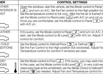
426 UNDERSTANDING YOUR INSTRUMENT PANEL CLIMATE CONTROLS The air conditioning and heating system is designed to make you comfortable in all types of weather. Dual-Zone Automatic Temperature Control (ATC) — If Equipped • The Automatic Temperature Control (ATC) allows both driver and front passenger seat occupants to select individual comfort settings. • When occupants in the vehicle select the AUTO mode operation, a comfort temperature can be set by using the temperature up and down buttons, and the auto blower operation will be set automatically. • The system provides set-and-forget operation for op- • The system can be controlled manually, if desired.
timum comfort and convenience.
The ATC system automatically maintains the interior comfort level desired by the driver and passenger.
Automatic Temperature Control (ATC) Panel
1. A/C Button Press and release to change the current Air Conditioning (A/C) setting, the indicator illuminates when A/C is ON. Performing this function will cause the ATC to switch into manual mode. 2. Recirculation Control Button Press and release to change the current setting, the indicator illuminates when ON. 3. Left Front Seat Occupant Temperature Display This display shows the temperature setting for the left front seat occupant. 4. Mode Display This display shows the current Mode selection (Panel, Bi-Level, Floor, Mix).
UNDERSTANDING YOUR INSTRUMENT PANEL 427
5. Blower Control Display This display shows the current Blower speed selection. 6. Right Front Seat Occupant Temperature Display This display shows the temperature setting for the right front seat occupant. 7. Front Defrost Button Press and release to change the current setting, the indicator illuminates when ON. Performing this function will cause the ATC to switch into manual mode. The blower will engage immediately if the Defrost mode is selected. 8. Passenger Temperature Control Up Button Provides the passenger with independent temperature control. Push the button for warmer temperature set- tings.
428 UNDERSTANDING YOUR INSTRUMENT PANEL 9. Passenger Temperature Control Down Button Provides the passenger with independent temperature control. Push the button for cooler temperature settings. 10. Auto Temperature Control Button Controls airflow temperature, distribution, volume, and the amount of air recirculation automatically. Press and release to select. Refer to “Automatic Operation” for more information. Performing this function will cause the ATC to switch between manual mode and automatic modes. 11. Blower Control There are seven blower speeds, the blower speed in- creases as you move the control to the right from the lowest blower setting. Performing this function will cause the ATC to switch into manual mode.
12. Climate Control OFF Button Press and release to turn the Climate Control OFF. 13. Mode Control Button Press and release to select between Modes (Panel, Bi- Level, Floor, Mix). Performing this function will cause the ATC to switch into manual mode. 14. SYNC Button Press and release to control the temperature setting for both zones from the driver temperature control. 15. Driver Temperature Control Down Button Provides the driver with independent temperature con- trol. Push the button for cooler temperature settings. 16. Driver Temperature Control Up Button Provides the driver with independent temperature con- trol. Push the button for warmer temperature settings.
17. Rear Control Button Provides the rear seat occupants with independent blower and temperature control. Push the button to activate the rear climate control and allow the rear seat occupants control of the rear blower and temperature settings. Automatic Operation 1. Press the AUTO button on the Automatic Temperature
Control (ATC) Panel.
2. Next, adjust the temperature you would like the system to maintain by adjusting the driver and front passenger temperature control buttons. Once the de- sired temperature is displayed, the system will achieve and automatically maintain that comfort level.
UNDERSTANDING YOUR INSTRUMENT PANEL 429
3. When the system is set up for your comfort level, it is not necessary to change the settings. You will experi- ence the greatest efficiency by simply allowing the system to function automatically.NOTE: • It is not necessary to move the temperature settings for cold or hot vehicles. The system automatically adjusts the temperature, mode and fan speed to provide comfort as quickly as possible. • The temperature can be displayed in U.S. or Metric units by selecting the US/M customer-programmable feature. Refer to the “Electronic Vehicle Information Center (EVIC) — Customer-Programmable Features (SETUP)” in this section of the manual.
To provide you with maximum comfort in the Automatic mode, during cold start-ups, the blower fan will remain on low until the engine warms up. The blower will increase in speed and transition into Auto mode.
430 UNDERSTANDING YOUR INSTRUMENT PANEL Manual Operation This system offers a full complement of manual override features. NOTE: Each of these features operate independently from each other. If any one feature is controlled manually, temperature control will continue to operate automatically. Blower Control
There are seven fixed blower speeds. Use the outer dial control to regulate the amount of air forced through the system in any mode you select. The blower speed increases as you move the control clockwise and decreases when you move the control counter-clockwise.
The blower fan speed can be set to any fixed speed by adjusting the blower control outer dial. The fan will now operate at a fixed speed until additional speeds are selected. This allows the front occupants to control the volume of air circulated in the vehicle and cancel the Auto mode. The operator can also select the direction of the airflow by selecting one of the following positions. Panel Mode
Air comes from the outlets in the instrument panel. Each of these outlets can be individually adjusted to direct the flow of air. The air vanes of the center outlets and outboard outlets can be moved up and down or side to side to regulate airflow direction. There is a shut off wheel located below the air vanes to shut off or adjust the amount of airflow from these outlets.
UNDERSTANDING YOUR INSTRUMENT PANEL 431
Bi-Level Mode
Defrost Mode
Air comes from the instrument panel outlets, floor outlets and defrost outlets.
NOTE: In many temperature positions, the Bi–Level mode is designed to provide cooler air out of the panel outlets and warmer air from the floor outlets. Floor Mode
Air comes from the floor outlets. A slight amount of air is directed through the defrost and side
window demister outlets. Mix Mode
Air comes from the floor, defrost and side window demist outlets. This mode works best in cold or snowy conditions. It allows you to stay comfortable while keeping the windshield clear.
Air comes from the windshield and side window demist outlets. Use Defrost mode with maximum temperature settings for best windshield and side win- dow defrosting. When the defrost mode is selected, the blower will automatically default to medium-high unless the blower is controlled manually. NOTE: While operating in the other modes, the system will not automatically sense the presence of fog, mist or ice on the windshield. Defrost mode must be manually selected to clear the windshield and side glass. Air Conditioning (A/C) The Air Conditioning (A/C) button allows the operator to manually activate or deactivate the air conditioning system. When in A/C mode and the ATC is set to a cool temperature, dehumidified air flows through the air
432 UNDERSTANDING YOUR INSTRUMENT PANEL outlets. If Economy mode is desired, press the A/C button to turn off the A/C mode in the ATC display and deactivate the A/C system. Also, make sure to select only Panel, Bi-Level or Floor modes. NOTE: • If the system is in Mix, Floor or Defrost Mode, the A/C can be turned off, but the A/C system shall remain active to prevent fogging of the windows. • If fog or mist appears on the windshield or side glass,
select Defrost mode and increase blower speed.
Recirculation Control
When outside air contains smoke, odors, or high humidity, or if rapid cooling is desired, you may wish to recirculate interior air by pressing the Recirculation control button. Re- circulation mode should only be used temporarily. The recirculation LED will illuminate when this button is
selected. Push the button a second time to turn off the Recirculation mode LED and allow outside air into the vehicle. NOTE: In cold weather, use of Recirculation mode may lead to excessive window fogging. The Recirculation mode is not allowed in the Defrost modes to improve window clearing operation. Recirculation will be dis- abled automatically if Defrost is selected. Rear Climate Control — If Equipped The Rear Climate Control system has floor air outlets, and overhead outlets at each outboard rear seating position. The unit provides warm or cool air through the floor and upper outlets. The rear blower and temperature controls for the rear seat passengers are located in the headliner, near the center of the vehicle.
If the rear system is off, changing the rear setting to a position other than off will turn the rear system on. If both the front and rear systems are off, the rear system will not turn on. The rear system will not operate with the front system off.
UNDERSTANDING YOUR INSTRUMENT PANEL 433
Rear Blower Control The primary control for the rear blower is on the front climate control unit, located on the instrument panel. Only when the Rear Control Icon is illuminated do the second row seat occupants have control of the rear blower speed. The rear blower control, located in the rear overhead console, has an off position and a range of blower speeds. This allows the second row seat occupants to control the volume of air circulated in the rear of the vehicle.
Rear Manual Climate Controls
1 – Rear Blower 2 – Rear Climate Control Icon
3 – Rear Temperature
434 UNDERSTANDING YOUR INSTRUMENT PANEL
CAUTION!
Interior air enters the Rear Manual Climate Control system through an intake grille, located in the right side trim panel behind the third row seats. The heater outlets are located in the right side trim panel, just behind the sliding door. Do not block or place objects directly in front of the inlet grille or heater outlets. The electrical system could overload, causing damage to the blower motor.
Rear Temperature Control Only when the Rear Control Icon is illuminated do the second row seat occupants have control of the rear temperature control knob. To change the temperature in the rear of the vehicle, rotate the temperature control knob counterclockwise for cold air, and clockwise for heated air.
Rear Mode Control Headliner Mode
Air comes from the outlets in the headliner. Each of these outlets can be individually adjusted to direct the flow of air. Moving the air vanes of the outlets to one side will shut off the airflow. Bi-Level Mode
Air comes from both the headliner outlets and the floor outlets.
NOTE: In many temperature positions, the Bi-Level mode is designed to provide cooler air out of the head- liner outlets and warmer air from the floor outlets. Floor Mode
Air comes from the floor outlets.
Operating Tips
Window Fogging Windows will fog on the inside when the humidity inside the vehicle is high. This often occurs in mild or cool temperatures when it’s rainy or humid. In most cases, turning the air conditioning (pressing the A/C button) on will clear the fog. Adjust the temperature control, air direction, and blower speed to maintain comfort. As the temperature gets colder, it may be necessary to direct air onto the windshield. Adjust the temperature control and blower speed to maintain comfort. Higher blower speeds will reduce fogging. Interior fogging on the windshield can be quickly removed by selecting the Defrost mode.
UNDERSTANDING YOUR INSTRUMENT PANEL 435
Regular cleaning of the inside of the windows with a non-filming cleaning solution (vinegar and water works very well) will help prevent contaminates (cigarette smoke, perfumes, etc.) from sticking to the windows. Contaminates increase the rate of window fogging. Summer OperationNOTE: In some cases during high temperature trailer tow operation the Air Conditioning system performance may be reduced. This is to help protect the engine from overheating during the high load condition.
436 UNDERSTANDING YOUR INSTRUMENT PANEL Your air conditioning system is also equipped with an automatic recirculation system. When the system senses a heavy load or high heat conditions, it may use partial Recirculation A/C mode to provide additional comfort. Winter Operation When operating the system during the winter months, make sure the air intake, located directly in front of the windshield, is free of ice, slush, snow, or other obstruc- tions.
Vacation Storage Any time you store your vehicle or keep it out of service (i.e., vacation) for two weeks or more, run the air conditioning system at idle for about five minutes in the fresh air and high blower setting. This will ensure adequate system lubrication to minimize the possibility of compressor damage when the system is started again.
Operating Tips Chart
UNDERSTANDING YOUR INSTRUMENT PANEL 437
STARTING AND OPERATING
CONTENTS 䡵 STARTING PROCEDURES . . . . . . . . . . . . . . ..444
▫ Automatic Transmission . . . . . . . . . . . . . . ..444
▫ Keyless Enter-N-Go™ . . . . . . . . . . . . . . . . ..445
▫ Normal Starting. . . . . . . . . . . . . . . . . . . . . . .446
▫ Extreme Cold Weather . . . . . . . . . . . . . . ..448
(Below –20°F Or −29°C) ▫ If Engine Fails To Start . . . . . . . . . . . . . . . ..448
▫ After Starting . . . . . . . . . . . . . . . . . . . . . . . .450
䡵 ENGINE BLOCK HEATER — IF EQUIPPED . . .450䡵 AUTOMATIC TRANSMISSION . . . . . . . . . . ..451
▫ Key Ignition Park Interlock. . . . . . . . . . . . . ..452
▫ Brake/Transmission Shift Interlock System . . .453
▫ Five-Speed Automatic Transmission(3.6L Engine) — If Equipped . . . . . . . . . . . ..453
▫ Gear Ranges . . . . . . . . . . . . . . . . . . . . . . . . .462
▫ Six-Speed Automatic Transmission(5.7L Engine) — If Equipped . . . . . . . . . . . ..461
▫ Gear Ranges . . . . . . . . . . . . . . . . . . . . . . . . .462440 STARTING AND OPERATING 䡵 ALL-WHEEL DRIVE OPERATION . . . . . . . . ..472
▫ Single-Speed Operating Instructions/Precautions (3.6L Engine) – If Equipped . . . . . . . . . . . . ..472▫ Electronically Shifted Transfer Case (Three-
Position Switch) (5.7L Engine) – If Equipped . .473
▫ Shifting Procedure . . . . . . . . . . . . . . . . . . . ..477
䡵 ON-ROAD DRIVING TIPS . . . . . . . . . . . . . . ..479
䡵 OFF-ROAD DRIVING TIPS . . . . . . . . . . . . . . ..480
▫ When To Use LOW Range – If Equipped . . . ..480
▫ Driving Through Water . . . . . . . . . . . . . . . ..480
▫ Driving In Snow, Mud And Sand . . . . . . . . ..482
▫ Hill Climbing . . . . . . . . . . . . . . . . . . . . . . . .482
▫ Traction Downhill . . . . . . . . . . . . . . . . . . . ..483
▫ After Driving Off-Road . . . . . . . . . . . . . . . ..483䡵 POWER STEERING . . . . . . . . . . . . . . . . . . . ..484
▫ 3.6L Engine . . . . . . . . . . . . . . . . . . . . . . . . . .484
▫ 5.7L Engine . . . . . . . . . . . . . . . . . . . . . . . . . .486
▫ Power Steering Fluid Check . . . . . . . . . . . . ..487䡵 FUEL SAVER TECHNOLOGY 5.7L ENGINE
ONLY – IF EQUIPPED . . . . . . . . . . . . . . . . . ..488
䡵 PARKING BRAKE . . . . . . . . . . . . . . . . . . . . . .488
䡵 ELECTRONIC BRAKE CONTROL SYSTEM . . . .490
▫ Anti-Lock Brake System (ABS) . . . . . . . . . . ..491
▫ Traction Control System (TCS) . . . . . . . . . . ..491
▫ Brake Assist System (BAS) . . . . . . . . . . . . . ..492
▫ Electronic Roll Mitigation (ERM) . . . . . . . . ..493
▫ Electronic Stability Control (ESC) . . . . . . . . ..493▫ Trailer Sway Control (TSC) . . . . . . . . . . . . ..497
▫ Hill Start Assist (HSA) . . . . . . . . . . . . . . . ..497
▫ Ready Alert Braking . . . . . . . . . . . . . . . . . ..500
▫ Rain Brake Support . . . . . . . . . . . . . . . . . . ..500
▫ ESC Activation/Malfunction Indicator LightAnd ESC OFF Indicator Light
. . . . . . . . . . ..500
䡵 TIRE SAFETY INFORMATION . . . . . . . . . . . ..502
▫ Tire Markings . . . . . . . . . . . . . . . . . . . . . . . .502
▫ Tire Identification Number (TIN). . . . . . . . . ..505
▫ Tire Terminology And Definitions . . . . . . . . ..506
▫ Tire Loading And Tire Pressure . . . . . . . . . ..507
䡵 TIRES — GENERAL INFORMATION. . . . . . . ..512
▫ Tire Pressure . . . . . . . . . . . . . . . . . . . . . . . .512STARTING AND OPERATING 441
▫ Tire Inflation Pressures . . . . . . . . . . . . . . . ..513
▫ Tire Pressures For High Speed Operation . . . .515
▫ Radial Ply Tires . . . . . . . . . . . . . . . . . . . . . .515
▫ All Season Tires – If Equipped . . . . . . . . . . ..515
▫ Summer Or Three Season Tires – If Equipped. .516
▫ Snow Tires . . . . . . . . . . . . . . . . . . . . . . . . . .516
▫ Spare Tire Matching Original Equipped TireAnd Wheel – If Equipped. . . . . . . . . . . . . . ..517
▫ Compact Spare Tire – If Equipped . . . . . . . ..517
▫ Full Size Spare – If Equipped . . . . . . . . . . . ..518
▫ Limited-Use Spare – If Equipped . . . . . . . . ..518
▫ Tire Spinning . . . . . . . . . . . . . . . . . . . . . . . .519
▫ Tread Wear Indicators . . . . . . . . . . . . . . . . ..520442 STARTING AND OPERATING
▫ Life Of Tire . . . . . . . . . . . . . . . . . . . . . . . . .520
▫ Replacement Tires . . . . . . . . . . . . . . . . . . . ..521
䡵 TIRE CHAINS (TRACTION DEVICES) . . . . . ..522
䡵 TIRE ROTATION RECOMMENDATIONS . . . ..524
䡵 TIRE PRESSURE MONITOR SYSTEM (TPMS) . .525
▫ Base System . . . . . . . . . . . . . . . . . . . . . . . . .528
▫ Premium System – If Equipped. . . . . . . . . . ..531
▫ General Information . . . . . . . . . . . . . . . . . ..535
䡵 FUEL REQUIREMENTS . . . . . . . . . . . . . . . . ..536
▫ 3.6L Engine – If Equipped . . . . . . . . . . . . . ..536
▫ 5.7L Engine – If Equipped . . . . . . . . . . . . . ..536
▫ Reformulated Gasoline . . . . . . . . . . . . . . . ..537
▫ Gasoline/Oxygenate Blends . . . . . . . . . . . . ..537▫ E-85 Usage In Non-Flex Fuel Vehicles . . . . . ..537
▫ MMT In Gasoline . . . . . . . . . . . . . . . . . . . ..538
▫ Materials Added To Fuel . . . . . . . . . . . . . . ..539
▫ Fuel System Cautions. . . . . . . . . . . . . . . . . ..539
▫ Carbon Monoxide Warnings . . . . . . . . . . . ..540䡵 FLEXIBLE FUEL (3.6L ENGINE ONLY) — IF
EQUIPPED . . . . . . . . . . . . . . . . . . . . . . . . . . .540
▫ E-85 General Information . . . . . . . . . . . . . ..540
▫ Ethanol Fuel (E-85) . . . . . . . . . . . . . . . . . . ..542
▫ Fuel Requirements . . . . . . . . . . . . . . . . . . ..542
▫ Selection Of Engine Oil For Flexible Fuel Vehicles (E-85) And Gasoline Vehicles . . . . . . . . . . . ..543
▫ Starting . . . . . . . . . . . . . . . . . . . . . . . . . . . .543
▫ Cruising Range . . . . . . . . . . . . . . . . . . . . . . .543▫ Replacement Parts . . . . . . . . . . . . . . . . . . ..544
▫ Maintenance . . . . . . . . . . . . . . . . . . . . . . . .544
䡵 ADDING FUEL . . . . . . . . . . . . . . . . . . . . . . . .544
▫ Fuel Filler Cap (Gas Cap) . . . . . . . . . . . . . ..544
▫ Loose Fuel Filler Cap Message . . . . . . . . . . ..547
䡵 VEHICLE LOADING . . . . . . . . . . . . . . . . . . ..548
. . . . . . . . . . . . . . . . . . ..548
䡵 TRAILER TOWING . . . . . . . . . . . . . . . . . . . ..550
▫ Common Towing Definitions . . . . . . . . . . . ..550
▫ Trailer Hitch Classification . . . . . . . . . . . . . ..555
▫ Trailer Towing Weights▫ Certification Label
(Maximum Trailer Weight Ratings) . . . . . . . ..556
STARTING AND OPERATING 443
▫ Trailer And Tongue Weight . . . . . . . . . . . . ..557
▫ Towing Requirements . . . . . . . . . . . . . . . . ..558
▫ Towing Tips . . . . . . . . . . . . . . . . . . . . . . . . .563
䡵 SNOW PLOW . . . . . . . . . . . . . . . . . . . . . . . . .565
䡵 RECREATIONAL TOWING (BEHIND. . . . . . . . . . . . . . . . . ..566
MOTORHOME, ETC.) ▫ Towing This Vehicle Behind Another Vehicle . .566
▫ Recreational Towing – Rear-Wheel DriveModels . . . . . . . . . . . . . . . . . . . . . . . . . . . . .567
▫ Recreational Towing – All-Wheel Drive Models
(Single-Speed Transfer Case) . . . . . . . . . . . . ..567
▫ Recreational Towing – All-Wheel Drive Models
(Two-Speed Transfer Case) . . . . . . . . . . . . . ..568
444 STARTING AND OPERATING STARTING PROCEDURES Before starting your vehicle, adjust your seat, adjust the inside and outside mirrors, fasten your seat belt, and if present, instruct all other occupants to buckle their seat belts.
WARNING!
• When leaving the vehicle, always remove the key fob from the ignition and lock your vehicle. • Never leave children alone in a vehicle, or with access to an unlocked vehicle. Allowing children to be in a vehicle unattended is dangerous for a number of reasons. A child or others could be seriously or fatally injured. Children should be warned not to touch the parking brake, brake pedal or the shift lever.
(Continued)
WARNING! (Continued)
• Do not leave the key fob in or near the vehicle (or in a location accessible to children), and do not leave a vehicle equipped with Keyless Enter-N- Go™ in the ACC or ON/RUN mode. A child could operate power windows, other controls, or move the vehicle.
Automatic Transmission The shift lever must be in the NEUTRAL or PARK position before you can start the engine. Apply the brakes before shifting into any driving gear.
CAUTION!
Damage to the transmission may occur if the follow- ing precautions are not observed: • Do not shift from REVERSE, PARK, or NEUTRAL into any forward gear when the engine is above idle speed. • Shift into PARK only after the vehicle has come to a complete stop. • Shift into or out of REVERSE only after the vehicle has come to a complete stop and the engine is at idle speed. • Before shifting into any gear, make sure your foot is firmly on the brake pedal.
Using Fob With Integrated Key (Tip Start) NOTE: Normal starting of either a cold or a warm engine is obtained without pumping or pressing the accelerator pedal.
STARTING AND OPERATING 445
Do not press the accelerator. Use the Fob with Integrated Key to briefly turn the ignition switch to the START position and release it as soon as the starter engages. The starter motor will continue to run, and it will disengage automatically when the engine is running. If the engine fails to start, the starter will disengage automatically in 10 seconds. If this occurs, turn the ignition switch to the LOCK position, wait 10 to 15 seconds, then repeat the “Normal Starting” procedure. Keyless Enter-N-Go™This feature allows the driver to operate the ignition switch with the push of a button, as long as the ENGINE START/ STOP button is installed and the Re- mote Start/Keyless Enter-N-Go™ FO- BIK is in the passenger compartment.
446 STARTING AND OPERATING Installing And Removing The ENGINE START/STOP Button Installing The Button 1. Remove the key fob from the ignition switch. 2. Insert the ENGINE START/STOP button into the igni-
tion switch with the lettering facing up and readable.
3. Press firmly on the center of the button to secure it into
position.
Removing The Button 1. The ENGINE START/STOP button can be removed
from the ignition switch for key fob use.
2. Insert the metal part of the emergency key under the chrome bezel at the 6 o’clock position and gently pry the button loose.
NOTE: The ENGINE START/STOP button should only be removed or inserted with the ignition in the OFF position (OFF position for Keyless Enter-N-Go™). Normal Starting
Using The ENGINE START/STOP Button 1. The transmission must be in PARK or NEUTRAL. 2. Press and hold the brake pedal while pressing the
ENGINE START/STOP button once.
3. The system takes over and attempts to start the vehicle. If the vehicle fails to start, the starter will disengage automatically after 10 seconds.
4. If you wish to stop the cranking of the engine prior to
the engine starting, press the button again.
NOTE: Normal starting of either a cold or a warm engine is obtained without pumping or pressing the accelerator pedal.
To Turn Off The Engine Using ENGINE START/STOP Button 1. Place the shift lever in PARK, then press and release
the ENGINE START/STOP button.
2. The ignition switch will return to the OFF position. 3. If the shift lever is not in PARK, the ENGINE START/ STOP button must be held for two seconds and vehicle speed must be above 5 mph (8 km/h) before the engine will shut off. The ignition switch position will remain in the ACC position until the shift lever is in PARK and the button is pressed twice to the OFF position. If the shift lever is not in PARK and the ENGINE START/STOP button is pressed once, the EVIC (if equipped) will display a “Vehicle Not In Park” message and the engine will remain running. Never leave a vehicle out of the PARK position, or it could roll.
STARTING AND OPERATING 447
NOTE: If the ignition switch is left in the ACC or RUN (engine not running) position and the transmission is in PARK, the system will automatically time out after 30 minutes of inactivity and the ignition will switch to the OFF position. Keyless Enter-N-Go™ Functions – With Driver’s Foot OFF The Brake Pedal/Clutch Pedal (In PARK Or NEUTRAL Position) The Keyless Enter-N-Go™ feature operates similar to an ignition switch. It has four positions, OFF, ACC, RUN and START. To change the ignition switch positions without starting the vehicle and use the accessories follow these steps. • Starting with the ignition switch in the OFF position: • Press the ENGINE START/STOP button once to change the ignition switch to the ACC position (EVIC displays “IGNITION MODE ACCESSORY”),448 STARTING AND OPERATING
• Press the ENGINE START/STOP button a second time to change the ignition switch to the RUN position (EVIC displays “IGNITION MODE RUN”), • Press the ENGINE START/STOP button a third time to return the ignition switch to the OFF position (EVIC displays “IGNITION MODE OFF”).
Extreme Cold Weather (Below –20°F Or −29°C) To ensure reliable starting at these temperatures, use of an externally powered electric engine block heater (avail- able from your authorized dealer) is recommended.
If Engine Fails To Start
WARNING!
• Never pour fuel or other flammable liquid into the throttle body air inlet opening in an attempt to start the vehicle. This could result in flash fire causing serious personal injury. • Do not attempt to push or tow your vehicle to get it started. Vehicles equipped with an automatic trans- mission cannot be started this way. Unburned fuel could enter the catalytic converter and once the engine has started, ignite and damage the converter and vehicle. • If the vehicle has a discharged battery, booster cables may be used to obtain a start from a booster battery or the battery in another vehicle. This type of start can be dangerous if done improperly. Refer to “Jump Starting” in “What To Do In Emergen- cies” for further information.
Clearing A Flooded Engine (Using ENGINE START/STOP Button) If the engine fails to start after you have followed the “Normal Starting” or “Extreme Cold Weather⬙ proce- dures, it may be flooded. To clear any excess fuel: 1. Press and hold the brake pedal. 2. Press the accelerator pedal all the way to the floor and
hold it.
3. Press and release the ENGINE START/STOP button
once.
The starter motor will engage automatically, run for 10 seconds, and then disengage. Once this occurs, release the accelerator pedal and the brake pedal, wait 10 to 15 seconds, then repeat the “Normal Starting” procedure.
STARTING AND OPERATING 449
Clearing A Flooded Engine (Using Fob With Integrated Key) If the engine fails to start after you have followed the “Normal Starting” or “Extreme Cold Weather” proce- dures, it may be flooded. To clear any excess fuel: 1. Press the accelerator pedal all the way to the floor and
hold it.
2. Turn the ignition switch to the START position and
release it as soon as the starter engages.
The starter motor will disengage automatically in 10 sec- onds. Once this occurs, release the accelerator pedal, turn the ignition switch to the LOCK position, wait 10 to 15 seconds, then repeat the “Normal Starting” procedure.
450 STARTING AND OPERATING
CAUTION!
To prevent damage to the starter, wait 10 to 15 seconds before trying again.
After Starting The idle speed is controlled automatically and it will decrease as the engine warms up.
ENGINE BLOCK HEATER — IF EQUIPPED The engine block heater warms the engine, and permits quicker starts in cold weather. Connect the cord to a standard 110-115 Volt AC electrical outlet with a grounded, three-wire extension cord. The engine block heater must be plugged in at least one hour to have an adequate warming effect on the engine.
The engine block heater cord is located: • 3.6L Engine – coiled and strapped to the engine oil • 5.7L Engine – bundled and fastened to the injector
dipstick tube.
harness.
WARNING!
Remember to disconnect the engine block heater cord before driving. Damage to the 110-115 Volt electrical cord could cause electrocution.
AUTOMATIC TRANSMISSION
CAUTION!
Damage to the transmission may occur if the follow- ing precautions are not observed: • Shift into PARK only after the vehicle has come to a complete stop. • Shift into or out of REVERSE only after the vehicle has come to a complete stop and the engine is at idle speed. • Do not shift between PARK, REVERSE, NEU- TRAL, or DRIVE when the engine is above idle speed. • Before shifting into any gear, make sure your foot is firmly pressing the brake pedal.
STARTING AND OPERATING 451
NOTE: You must press and hold the brake pedal while shifting out of PARK.WARNING!
• Unintended movement of a vehicle could injure those in or near the vehicle. As with all vehicles, you should never exit a vehicle while the engine is running. Before exiting a vehicle, always apply the parking brake, shift the transmission into PARK, turn the engine OFF, and remove the key fob. When the ignition is in the OFF position, the shift lever is locked in PARK, securing the vehicle against un- wanted movement.
(Continued)
452 STARTING AND OPERATING
WARNING! (Continued)
• It is dangerous to shift out of PARK or NEUTRAL if the engine speed is higher than idle speed. If your foot is not firmly pressing the brake pedal, the vehicle could accelerate quickly forward or in re- verse. You could lose control of the vehicle and hit someone or something. Only shift into gear when the engine is idling normally and your foot is firmly pressing the brake pedal. • When leaving the vehicle, always remove the key fob and lock your vehicle. • Never leave children alone in a vehicle, or with access to an unlocked vehicle. Allowing children to be in a vehicle unattended is dangerous for a number of reasons. A child or others could be seriously or fatally injured.
(Continued)
WARNING! (Continued)
• Children should be warned not to touch the park- ing brake, brake pedal or the shift lever. • Do not leave the key fob in or near the vehicle (or in a location accessible to children), and do not leave Keyless Enter-N-Go™ in the ACC or ON/ RUN position. A child could operate power win- dows, other controls, or move the vehicle.
Key Ignition Park Interlock This vehicle is equipped with a Key Ignition Park Inter- lock which requires the shift lever to be in PARK before the ignition switch can be turned to the OFF position. The key fob can only be removed from the ignition when the ignition is in the OFF position, and the shift lever is locked in PARK whenever the ignition switch is in the OFF position.
NOTE: If a malfunction occurs, the system will trap the key fob in the ignition switch to warn you that this safety feature is inoperable. The engine can be started and stopped but the key fob cannot be removed until you obtain service. Brake/Transmission Shift Interlock System This vehicle is equipped with a Brake Transmission Shift Interlock system (BTSI) that holds the shift lever in PARK unless the brakes are applied. To shift the transmission out of PARK, the ignition switch must be turned to the ON/RUN position (engine running or not) and the brake pedal must be pressed. Five-Speed Automatic Transmission (3.6L Engine) — If Equipped The shift lever position display (located in the instrument cluster) indicates the transmission gear range. You must press the brake pedal to move the shift lever out of PARK
STARTING AND OPERATING 453
(refer to “Brake/Transmission Shift Interlock System” in this section). To drive, move the shift lever from PARK or NEUTRAL to the DRIVE position. The electronically-controlled transmission provides a precise shift schedule. The transmission electronics are self-calibrating; therefore, the first few shifts on a new vehicle may be somewhat abrupt. This is a normal condition, and precision shifts will develop within a few hundred miles (kilometers). Only shift from DRIVE to PARK or REVERSE when the accelerator pedal is released and the vehicle is stopped. Be sure to keep your foot on the brake pedal when moving the shift lever between these gears. The transmission shift lever has only PARK, REVERSE, NEUTRAL, and DRIVE shift positions. Manual down- shifts can be made using the Electronic Range Select (ERS) shift control (refer to “Electronic Range Select (ERS) Operation” in this section). Moving the shift lever to the454 STARTING AND OPERATING left or right (-/+) while in the DRIVE position will select the highest available transmission gear, and will display that gear in the instrument cluster as 3, 2, 1.
Shift Lever
Gear Ranges DO NOT race the engine when shifting from PARK or NEUTRAL into another gear range.
NOTE: • After selecting any gear range, wait a moment to allow the selected gear to engage before accelerating. This is especially important when the engine is cold. • If there is a need to restart the engine, be sure to cycle the ignition to the OFF position before restarting. Transmission gear engagement may be delayed after restarting the engine if the key is not cycled to the OFF position first.
PARK This range supplements the parking brake by locking the transmission. The engine can be started in this range. Never attempt to use PARK while the vehicle is in motion. Apply the parking brake when leaving the vehicle in this range. When parking on a level surface, you may place the shift lever in PARK first, and then apply the parking brake.
STARTING AND OPERATING 455
WARNING! (Continued)
• It is dangerous to shift out of PARK or NEUTRAL if the engine speed is higher than idle speed. If your foot is not firmly pressing the brake pedal, the vehicle could accelerate quickly forward or in re- verse. You could lose control of the vehicle and hit someone or something. Only shift into gear when the engine is idling normally and your foot is firmly pressing the brake pedal.
(Continued)
When parking on a hill, apply the parking brake before placing the shift lever in PARK, otherwise the load on the transmission locking mechanism may make it difficult to move the shift lever out of PARK. As an added precau- tion, turn the front wheels toward the curb on a downhill grade and away from the curb on an uphill grade.
WARNING!
• Never use the PARK position as a substitute for the parking brake. Always apply the parking brake fully when parked to guard against vehicle move- ment and possible injury or damage. • Your vehicle could move and injure you and others if it is not completely in PARK. Check by trying to move the shift lever out of PARK with the brake pedal released. Make sure the transmission is in PARK before leaving the vehicle.
(Continued)
456 STARTING AND OPERATING
WARNING! (Continued)
• Unintended movement of a vehicle could injure those in or near the vehicle. As with all vehicles, you should never exit a vehicle while the engine is running. Before exiting a vehicle, always apply the parking brake, shift the transmission into PARK turn the engine OFF, and remove the key fob. When the ignition is in the LOCK/OFF position, the shift lever is locked in PARK, securing the vehicle against unwanted movement. • When leaving the vehicle, always remove the key fob and lock your vehicle. • Never leave children alone in a vehicle, or with access to an unlocked vehicle.
(Continued)
WARNING! (Continued)
• Allowing children to be in a vehicle unattended is dangerous for a number of reasons. A child or others could be seriously or fatally injured. Chil- dren should be warned not to touch the parking brake, brake pedal or the shift lever. • Do not leave the key fob in or near the vehicle (or in a location accessible to children), and do not leave Keyless Enter-N-Go™ in the ACC or ON/ RUN position. A child could operate power win- dows, other controls, or move the vehicle.
CAUTION!
• Before moving the shift lever out of PARK, you must turn the ignition switch from the OFF posi- tion to the ON/RUN position, and also press the brake pedal. Otherwise, damage to the shift lever could result. • DO NOT race the engine when shifting from PARK or NEUTRAL into another gear range, as this can damage the drivetrain.
The following indicators should be used to ensure that you have engaged the shift lever into the PARK position: • When shifting into PARK, firmly move the shift lever all the way forward and to the left until it stops and is fully seated.
STARTING AND OPERATING 457
• Look at the shift lever position display and verify that • With brake pedal released, verify that the shift lever
it indicates the PARK position.
will not move out of PARK.
REVERSE This range is for moving the vehicle backward. Shift into REVERSE only after the vehicle has come to a complete stop. NEUTRAL Use this range when the vehicle is standing for prolonged periods with the engine running. The engine may be started in this range. Apply the parking brake and shift the transmission into PARK if you must leave the vehicle.
458 STARTING AND OPERATING
WARNING!
Do not coast in NEUTRAL and never turn off the ignition to coast down a hill. These are unsafe practices that limit your response to changing traffic or road conditions. You might lose control of the vehicle and have a collision.
CAUTION!
Towing the vehicle, coasting, or driving for any other reason with the transmission in NEUTRAL can cause severe transmission damage. Refer to “Recreational Towing” in “Starting And Operating” and “Towing A Disabled Vehicle” in “What To Do In Emergencies” for further information.
DRIVE This range should be used for most city and highway driving. It provides the smoothest upshifts and down- shifts, and the best fuel economy. The transmission automatically upshifts through underdrive first, second, and third gears, direct fourth gear and overdrive fifth gear. The DRIVE position provides optimum driving characteristics under all normal operating conditions. When frequent transmission shifting occurs (such as when operating the vehicle under heavy loading condi- tions, in hilly terrain, traveling into strong head winds, or while towing heavy trailers), use the AutoStick® shift control (refer to “AutoStick®” in this section) to select a lower gear. Under these conditions, using a lower gear will improve performance and extend transmission life by reducing excessive shifting and heat buildup.
Transmission Limp Home Mode Transmission function is monitored electronically for abnormal conditions. If a condition is detected that could result in transmission damage, Transmission Limp Home Mode is activated. In this mode, the transmission remains in direct gear regardless of which forward gear is se- lected. PARK, REVERSE, and NEUTRAL will continue to operate. The Malfunction Indicator Light (MIL) may be illuminated. Limp Home Mode allows the vehicle to be driven to an authorized dealer for service without dam- aging the transmission. In the event of a momentary problem, the transmission can be reset to regain all forward gears by performing the following steps: 1. Stop the vehicle. 2. Shift the transmission into PARK. 3. Turn the ignition switch to the LOCK/OFF position.
STARTING AND OPERATING 459
4. Wait approximately 10 seconds. 5. Restart the engine. 6. Shift into the desired gear range. If the problem is no longer detected, the transmission will return to normal operation.
NOTE: Even if the transmission can be reset, we recom- mend that you visit your authorized dealer at your earliest possible convenience. Your authorized dealer has diagnos- tic equipment to determine if the problem could recur. If the transmission cannot be reset, authorized dealer service is required. Electronic Range Select (ERS) Operation The Electronic Range Select (ERS) shift control allows the driver to limit the highest available gear when the shift lever is in the DRIVE position. For example, if you shift the transmission into 3 (third gear), the transmission will never shift above third gear, but will shift down into second and first gears normally.
460 STARTING AND OPERATING You can switch between DRIVE and ERS mode at any vehicle speed. When the shift lever is in the DRIVE position, the transmission will operate automatically, shifting between all available gears. Tapping the shift lever to the left (-) will downshift the transmission, activate ERS mode, display the current gear in the instrument cluster, and maintain that gear as the top available gear. Once in ERS mode, tapping the shift lever to the left (-) or right (+) will change the top available gears. To exit ERS mode, simply press and hold the shift lever to the right (+) until “D” is once again displayed in the shift lever position indicator in the instrument cluster.
WARNING!
Do not downshift for additional engine braking on a slippery surface. The drive wheels could lose their grip and the vehicle could skid, causing a collision or personal injury.
Screen Display Actual Gear(s) Allowed
1-2
1-3
1-4
1-5
NOTE: To select the proper gear position for maximum deceleration (engine braking), simply press and hold the shift lever to the left (-). The transmission will shift to the range from which the vehicle can best be slowed down.
Overdrive Operation The automatic transmission includes an electronically controlled Overdrive (fifth gear). The transmission will automatically shift into Overdrive if the following con- ditions are present: • the shift lever is in the DRIVE position, • vehicle speed is sufficiently high, and • the driver is not heavily pressing the accelerator. Six-Speed Automatic Transmission (5.7L Engine) — If Equipped The shift lever position display (located in the instrument cluster) indicates the transmission gear range. You must press the brake pedal to move the shift lever out of PARK
STARTING AND OPERATING 461
(refer to “Brake/Transmission Shift Interlock System” in this section). To drive, move the shift lever from PARK or NEUTRAL to the DRIVE position. The electronically-controlled transmission provides a precise shift schedule. The transmission electronics are self-calibrating; therefore, the first few shifts on a new vehicle may be somewhat abrupt. This is a normal condition, and precision shifts will develop within a few hundred miles (kilometers). Only shift from DRIVE to PARK or REVERSE when the accelerator pedal is released and the vehicle is stopped. Be sure to keep your foot on the brake pedal when moving the shift lever between these gears.462 STARTING AND OPERATING The transmission shift lever has only PARK, REVERSE, NEUTRAL, and DRIVE shift positions. Manual down- shifts can be made using the Electronic Range Select (ERS) shift control (refer to “Electronic Range Select (ERS) Operation” in this section). Moving the shift lever to the left or right (-/+) while in the DRIVE position will select the highest available transmission gear, and will display that gear in the instrument cluster as 6, 5, 4, 3, 2, 1.
Shift Lever
Gear Ranges DO NOT race the engine when shifting from PARK or NEUTRAL into another gear range.
NOTE: • After selecting any gear range, wait a moment to allow the selected gear to engage before accelerating. This is especially important when the engine is cold. • If there is a need to restart the engine, be sure to cycle the ignition to the OFF position before restarting. Transmission gear engagement may be delayed after restarting the engine if the key is not cycled to the OFF position first.
PARK This range supplements the parking brake by locking the transmission. The engine can be started in this range. Never attempt to use PARK while the vehicle is in motion. Apply the parking brake when leaving the vehicle in this range. When parking on a level surface, you may place the shift lever in PARK first, and then apply the parking brake.
STARTING AND OPERATING 463
When parking on a hill, apply the parking brake before placing the shift lever in PARK, otherwise the load on the transmission locking mechanism may make it difficult to move the shift lever out of PARK. As an added precau- tion, turn the front wheels toward the curb on a downhill grade and away from the curb on an uphill grade.WARNING!
• Never use the PARK position as a substitute for the parking brake. Always apply the parking brake fully when parked to guard against vehicle move- ment and possible injury or damage. • Your vehicle could move and injure you and others if it is not completely in PARK. Check by trying to move the shift lever out of PARK with the brake pedal released. Make sure the transmission is in PARK before leaving the vehicle.
(Continued)
464 STARTING AND OPERATING
WARNING! (Continued)
• It is dangerous to shift out of PARK or NEUTRAL if the engine speed is higher than idle speed. If your foot is not firmly pressing the brake pedal, the vehicle could accelerate quickly forward or in re- verse. You could lose control of the vehicle and hit someone or something. Only shift into gear when the engine is idling normally and your foot is firmly pressing the brake pedal.
(Continued)
WARNING! (Continued)
• Unintended movement of a vehicle could injure those in or near the vehicle. As with all vehicles, you should never exit a vehicle while the engine is running. Before exiting a vehicle, always apply the parking brake, shift the transmission into PARK turn the engine OFF, and remove the key fob. When the ignition is in the LOCK/OFF position, the shift lever is locked in PARK, securing the vehicle against unwanted movement. • When leaving the vehicle, always remove the key fob and lock your vehicle. • Never leave children alone in a vehicle, or with access to an unlocked vehicle.
(Continued)
WARNING! (Continued)
• Allowing children to be in a vehicle unattended is dangerous for a number of reasons. A child or others could be seriously or fatally injured. Chil- dren should be warned not to touch the parking brake, brake pedal or the shift lever. • Do not leave the key fob in or near the vehicle (or in a location accessible to children), and do not leave Keyless Enter-N-Go™ in the ACC or ON/ RUN position. A child could operate power win- dows, other controls, or move the vehicle.
STARTING AND OPERATING 465
CAUTION!
• Before moving the shift lever out of PARK, you must turn the ignition switch from the OFF posi- tion to the ON/RUN position, and also press the brake pedal. Otherwise, damage to the shift lever could result. • DO NOT race the engine when shifting from PARK or NEUTRAL into another gear range, as this can damage the drivetrain.
The following indicators should be used to ensure that you have engaged the shift lever into the PARK position: • When shifting into PARK, firmly move the shift lever all the way forward and to the left until it stops and is fully seated.
466 STARTING AND OPERATING
• Look at the shift lever position display and verify that • With brake pedal released, verify that the shift lever
it indicates the PARK position.
will not move out of PARK.
REVERSE This range is for moving the vehicle backward. Shift into REVERSE only after the vehicle has come to a complete stop. NEUTRAL Use this range when the vehicle is standing for prolonged periods with the engine running. The engine may be started in this range. Apply the parking brake and shift the transmission into PARK if you must leave the vehicle.
WARNING!
Do not coast in NEUTRAL and never turn off the ignition to coast down a hill. These are unsafe practices that limit your response to changing traffic or road conditions. You might lose control of the vehicle and have a collision.
CAUTION!
Towing the vehicle, coasting, or driving for any other reason with the transmission in NEUTRAL can cause severe transmission damage. Refer to “Recreational Towing” in “Starting And Operating” and “Towing A Disabled Vehicle” in “What To Do In Emergencies” for further information.
DRIVE This range should be used for most city and highway driving. It provides the smoothest upshifts and down- shifts, and the best fuel economy. The transmission automatically upshifts through underdrive first and sec- ond gears, direct third gear and overdrive fourth and fifth gears. The DRIVE position provides optimum driv- ing characteristics under all normal operating conditions. To access all six available gears, you must use the Electronic Range Select (ERS) shift control (refer to “Elec- tronic Range Select (ERS) Operation” in this section). When frequent transmission shifting occurs (such as when operating the vehicle under heavy loading condi- tions, in hilly terrain, traveling into strong head winds, or while towing heavy trailers), use the Electronic Range Select (ERS) shift control (refer to “Electronic Range Select (ERS) Operation” in this section) to select a lower
STARTING AND OPERATING 467
gear range. Under these conditions, using a lower gear range will improve performance and extend transmission life by reducing excessive shifting and heat buildup. If the transmission temperature exceeds normal operat- ing limits, the powertrain controller will modify the transmission shift schedule and expand the range of