- 2011 Dodge Durango Owners Manuals
- Dodge Durango Owners Manuals
- 2008 Dodge Durango Owners Manuals
- Dodge Durango Owners Manuals
- 2009 Dodge Durango Owners Manuals
- Dodge Durango Owners Manuals
- 2007 Dodge Durango Owners Manuals
- Dodge Durango Owners Manuals
- 2004 Dodge Durango Owners Manuals
- Dodge Durango Owners Manuals
- 2013 Dodge Durango Owners Manuals
- Dodge Durango Owners Manuals
- 2005 Dodge Durango Owners Manuals
- Dodge Durango Owners Manuals
- 2006 Dodge Durango Owners Manuals
- Dodge Durango Owners Manuals
- 2012 Dodge Durango Owners Manuals
- Dodge Durango Owners Manuals
- Download PDF Manual
-
UNDERSTANDING THE FEATURES OF YOUR VEHICLE
CONTENTS
䡵 Mirrors . . . . . . . . . . . . . . . . . . . . . . . . . . . . . . .84
▫ Inside Day/Night Mirror . . . . . . . . . . . . . . . . .84
▫ Automatic Dimming Mirror — If Equipped . . . .84
▫ Outside Mirrors . . . . . . . . . . . . . . . . . . . . . . .85
▫ Exterior Mirrors Folding Feature — IfEquipped . . . . . . . . . . . . . . . . . . . . . . . . . . . .85
▫ Electric Remote-Control Mirrors . . . . . . . . . . . .86
▫ Illuminated Vanity Mirrors — If Equipped . . . .87
▫ Heated Mirrors — If Equipped . . . . . . . . . . . . .87▫ Automatic Dimming Driver’s Exterior
Mirror — If Equipped . . . . . . . . . . . . . . . . . . .88
䡵 Hands–Free Communication (UConnect™) — If
Equipped . . . . . . . . . . . . . . . . . . . . . . . . . . . . .88
▫ Operations . . . . . . . . . . . . . . . . . . . . . . . . . . .90
▫ Phone Call Features . . . . . . . . . . . . . . . . . . . .97
▫ UConnect™ System Features . . . . . . . . . . . . . .99
▫ Advanced Phone Connectivity . . . . . . . . . . . . 104
▫ Things You Should Know About YourUConnect™ System . . . . . . . . . . . . . . . . . . . . 106
80 UNDERSTANDING THE FEATURES OF YOUR VEHICLE
䡵 Seats . . . . . . . . . . . . . . . . . . . . . . . . . . . . . . . . 111
▫ Front Seat Manual Seat Adjustment . . . . . . . . 111
▫ Front Seats Manual Seat Recliners . . . . . . . . . . 112
▫ Manual Lumbar Support Adjustment — IfEquipped . . . . . . . . . . . . . . . . . . . . . . . . . . . 113
▫ Adjustable Head Restraints — All Seating
Positions . . . . . . . . . . . . . . . . . . . . . . . . . . . 113
▫ 8 - Way Driver’s Power Seat — If Equipped . . 114
▫ 4 - Way Passenger’s Power Seat — IfEquipped . . . . . . . . . . . . . . . . . . . . . . . . . . . 115
▫ Front Heated Seats — If Equipped . . . . . . . . . 115
▫ Second Row 40/20/40 Seat — Fold AndTumble . . . . . . . . . . . . . . . . . . . . . . . . . . . . 117
▫ Third Row Seat Bench — If Equipped . . . . . . . 120▫ Third Row 60/40 Folding — If Equipped . . . . 122
䡵 Driver Memory System — If Equipped . . . . . . . 125▫ Setting Memory Positions And Linking Remote
Keyless Entry Transmitter To Memory . . . . . . . 126
▫ Memory Position Recall . . . . . . . . . . . . . . . . . 127
▫ To Disable A Transmitter Linked To Memory . . 127
▫ Self-Limiting Control . . . . . . . . . . . . . . . . . . . 128
▫ Driver Easy Exit And Easy Entry Control . . . . 128
䡵 To Open And Close The Hood . . . . . . . . . . . . . 129
䡵 Lights . . . . . . . . . . . . . . . . . . . . . . . . . . . . . . . 131
▫ Interior Lights . . . . . . . . . . . . . . . . . . . . . . . 132
▫ Battery Saver . . . . . . . . . . . . . . . . . . . . . . . . 132
▫ Headlight Delay . . . . . . . . . . . . . . . . . . . . . . 133▫ Automatic Headlights — If Equipped . . . . . . . 133
▫ Headlights, Parking Lights, Panel Lights . . . . . 134
▫ Illuminated Entry . . . . . . . . . . . . . . . . . . . . . 134
▫ Daytime Running Lights (Canada Only) . . . . . 134
▫ Lights-On Reminder . . . . . . . . . . . . . . . . . . . 135
▫ Fog Lights — If Equipped . . . . . . . . . . . . . . . 135
䡵 Multifunction Control Lever . . . . . . . . . . . . . . . 135
▫ Turn Signals . . . . . . . . . . . . . . . . . . . . . . . . . 136
▫ Passing Light . . . . . . . . . . . . . . . . . . . . . . . . 136
▫ High Beam / Low Beam Select Switch . . . . . . 137
▫ Windshield Wipers . . . . . . . . . . . . . . . . . . . . 137
▫ Windshield Washers . . . . . . . . . . . . . . . . . . . 139UNDERSTANDING THE FEATURES OF YOUR VEHICLE 81
䡵 Electronic Stability Program (ESP) Off Control
▫ Adjustment
Switch — If Equipped . . . . . . . . . . . . . . . . . . . 139
䡵 Tilt Steering Column . . . . . . . . . . . . . . . . . . . . 140
䡵 Driver Adjustable Pedals — If Equipped . . . . . . 141
. . . . . . . . . . . . . . . . . . . . . . . . . 142
䡵 Electronic Speed Control — If Equipped . . . . . . 142
▫ To Activate . . . . . . . . . . . . . . . . . . . . . . . . . . 143
▫ To Set At A Desired Speed . . . . . . . . . . . . . . . 143
▫ To Deactivate . . . . . . . . . . . . . . . . . . . . . . . . 143
▫ To Resume Speed . . . . . . . . . . . . . . . . . . . . . 144
▫ To Vary The Speed Setting . . . . . . . . . . . . . . . 144
▫ To Accelerate For Passing . . . . . . . . . . . . . . . 14582 UNDERSTANDING THE FEATURES OF YOUR VEHICLE
䡵 Electronic Brake Control System . . . . . . . . . . . . 146
▫ ABS (Anti-Lock Brake System) . . . . . . . . . . . . 146
▫ BAS (Brake Assist System) – If EquippedWith ESP . . . . . . . . . . . . . . . . . . . . . . . . . . . 147
▫ TCS (Traction Control System) – If Equipped
▫ ERM (Electronic Roll Mitigation) ▫ ESP (Electronic Stability Program)
With ESP . . . . . . . . . . . . . . . . . . . . . . . . . . . 149
. . . . . . . . . . 149
. . . . . . . . . 150
䡵 Overhead Console . . . . . . . . . . . . . . . . . . . . . . 155
▫ Courtesy/Reading Lights . . . . . . . . . . . . . . . . 155
䡵 Compass/Temperature Mini-Trip Computer . . . . 156
▫ US/M Button . . . . . . . . . . . . . . . . . . . . . . . . 156
▫ Reset Button . . . . . . . . . . . . . . . . . . . . . . . . . 156
▫ Global Reset . . . . . . . . . . . . . . . . . . . . . . . . . 157▫ Step Button . . . . . . . . . . . . . . . . . . . . . . . . . 157
▫ Average Fuel Economy (AVG ECO) . . . . . . . . 158
▫ Distance To Empty (DTE) . . . . . . . . . . . . . . . 158
▫ Trip Odometer (ODO) . . . . . . . . . . . . . . . . . . 158
▫ Elapsed Time (ET) . . . . . . . . . . . . . . . . . . . . . 158
▫ C/T Button . . . . . . . . . . . . . . . . . . . . . . . . . 159
▫ Compass/Temperature Display . . . . . . . . . . . 159
▫ Automatic Compass Calibration . . . . . . . . . . . 159
▫ Manual Compass Calibration . . . . . . . . . . . . . 160
▫ To Put Into a Calibration Mode . . . . . . . . . . . 160
▫ Outside Temperature . . . . . . . . . . . . . . . . . . . 161
䡵 Garage Door Opener — If Equipped . . . . . . . . . 162
▫ Programming HomeLink . . . . . . . . . . . . . . . . 163▫ Canadian Programming/Gate Programming . . 166
▫ Using HomeLink . . . . . . . . . . . . . . . . . . . . . 166
▫ Erasing HomeLink Buttons . . . . . . . . . . . . . . 166
▫ Reprogramming a Single HomeLink Button . . . 167
▫ Security . . . . . . . . . . . . . . . . . . . . . . . . . . . . 167
䡵 Power Sunroof — If Equipped . . . . . . . . . . . . . 168
▫ Express Open Feature . . . . . . . . . . . . . . . . . . 168
▫ Wind Buffeting . . . . . . . . . . . . . . . . . . . . . . . 169UNDERSTANDING THE FEATURES OF YOUR VEHICLE 83
▫ Sunroof Maintenance . . . . . . . . . . . . . . . . . . . 170
䡵 Electrical Power Outlets . . . . . . . . . . . . . . . . . . 170▫ Electrical Outlet Use With Engine Off
(Battery Fed Configuration) . . . . . . . . . . . . . . 171
䡵 Floor Console . . . . . . . . . . . . . . . . . . . . . . . . . 172
. . . . . . . . . . . . . . . . . 172
䡵 Factory Installed Roof Luggage Rack . . . . . . . . . 174
䡵 Cargo Management System—If Equipped . . . . . . 176▫ Floor Console Features
84 UNDERSTANDING THE FEATURES OF YOUR VEHICLE
MIRRORS
Inside Day/Night Mirror The mirror should be adjusted to center on the view through the rear window. A two-point pivot system allows for horizontal and vertical adjustment of the mirror.
Annoying headlight glare can be reduced by moving the small control under the mirror to the night position (toward rear of truck). The mirror should be adjusted while set in the day position (toward windshield). Automatic Dimming Mirror — If Equipped This mirror will automatically adjust for annoying head- light glare from vehicles behind you. You can turn the feature on or off by pressing the button at the base of the mirror. A light in the button will indicate when the dimming feature is activated. This option also controls the driver side mirror when it is equipped with auto dimming glass.
Day/Night Mirror
UNDERSTANDING THE FEATURES OF YOUR VEHICLE 85
CAUTION!
To avoid damage to the mirror during cleaning, never spray any cleaning solution directly onto the mirror. Apply the solution onto a clean cloth and wipe the mirror clean.
Outside Mirrors To receive maximum benefit, adjust the outside mirror(s) to center on the adjacent lane of traffic with a slight overlap of the view obtained on the inside mirror. Exterior Mirrors Folding Feature — If Equipped Folding exterior mirrors are hinged and may be moved either forward or rearward to resist damage.
Automatic Dimming Mirror
86 UNDERSTANDING THE FEATURES OF YOUR VEHICLE
Electric Remote-Control Mirrors The controls for the power mirrors are located on the driver’s door trim panel.
Remote Control Mirrors Switch
Mirror Directions
To adjust a mirror, turn the control wand toward the left or right mirror positions indicated. Tilt the control wand in the direction you want the mirror to move. When finished adjusting the mirror, turn the control to the center position to prevent accidentally moving a mirror.
WARNING!
Vehicles and other objects seen in the right side convex mirror will look smaller and farther away than they really are. Relying too much on your right side mirror could cause you to collide with another vehicle or other object. Use your inside mirror when judging the size or distance of a vehicle seen in the right side mirror.
Illuminated Vanity Mirrors — If Equipped An illuminated vanity mirror is on each sun visor. To use the mirror, rotate the sun visor down and swing the mirror cover upward. The lights will turn on automati- cally. Closing the mirror cover turns off the light.
UNDERSTANDING THE FEATURES OF YOUR VEHICLE 87
Lighted Vanity Mirror
Heated Mirrors — If Equipped Heated mirrors are automatically activated when you depress the rear window defroster switch located on the instrument panel. The light will illuminate to indicate
88 UNDERSTANDING THE FEATURES OF YOUR VEHICLE
that the heating elements are ON. Turning Off the rear window defroster or the ignition will deactivate the heated mirrors. Automatic Dimming Driver’s Exterior Mirror — If Equipped This mirror will automatically adjust for annoying light glare from vehicles behind you. This feature is controlled by the inside mirror and can be turned off by pressing the button at the base of the inside mirror.
HANDS–FREE COMMUNICATION (UConnect™) — IF EQUIPPED UConnect™ is a voice-activated, hands-free, in- vehicle communications system. UConnect™ allows you to dial a phone number with your cellular phone using simple voice commands (e.g., ⬙Call” ѧ “Mike” ѧ”Work⬙ or ⬙Dial”
ѧ “248-555-1212⬙). Your cellular phone’s audio is trans- mitted through your vehicle’s audio system; the system will automatically mute your radio when using the UConnect™ system. NOTE: The UConnect™ system use requires a cellular phone equipped with the Bluetooth ⬙Hands-Free Profile,⬙ version 0.96 or higher. See www.chrysler.com/uconnect for supported phones. UConnect™ allows you to transfer calls between the system and your cellular phone as you enter or exit your vehicle, and enables you to mute the system’s micro- phone for private conversation. The UConnect™ phonebook enables you to store up to 32
names and four numbers per name. Each language has a separate 32 name phonebook accessible only in that language. This system is driven through your Blue- tooth™ Hands-Free profile cellular phone. UConnect™ features Bluetooth™ technology - the global standardthat enables different electronic devices to connect to each other without wires or a docking station, so UCon- nect works no matter where you stow your cellular phone (be it your purse, pocket, or briefcase), as long as your phone is turned on and has been paired to the vehicle’s UConnect™ system. The UConnect™ system allows up to seven cellular phones to be linked to system. Only one linked (or paired) cellular phone can be used with the system at a time. The system is available in English, Spanish, or French languages (as equipped). The rearview mirror contains the microphone for the system and the control buttons that will enable you to access the system.
UNDERSTANDING THE FEATURES OF YOUR VEHICLE 89
UConnect™ Switches
The UConnect™ system can be used with any Hands- Free Profile certified Bluetooth™ cellular phone. See www.chrysler.com/uconnect for supported phones. If your cellular phone supports a different profile (e.g.,
90 UNDERSTANDING THE FEATURES OF YOUR VEHICLE
Headset Profile), you may not be able to use any UCon- nect™ features. Refer to your cellular service provider or the phone manufacturer for details. The UConnect™ system is fully integrated with the vehicle’s audio system. The volume of the UConnect™ system can either be adjusted from the radio volume control knob, or from the steering wheel radio control (right switch), if so equipped. The radio display will be used for visual prompts from the UConnect™ system such as ⬙CELL⬙ or caller ID on certain radios. Operations Voice commands can be used to operate the UConnect™ system and to navigate through the UConnect™ menu structure. Voice commands are required after most UConnect™ system prompts. You will be prompted for a specific command and then guided through the available options.
• Prior to giving a voice command, one must wait for the voice on beep, which follows the ⬙Ready⬙ prompt or another prompt. • For certain operations, compound commands can be used. For example, instead of saying ⬙Setup⬙ and then ⬙Phone Pairing,⬙ the following compound command can be said: ⬙Setup Phone Pairing.⬙ • For each feature explanation in this section, only the combined form of the voice command is given. You can also break the commands into parts and say each part of the command, when you are asked for it. For example, you can either use the combined form voice command ⬙Phonebook New Entry,⬙ or you can break the combined form command into two voice com- mands: ⬙Phonebook⬙ and ⬙New Entry.⬙ Please remem- ber, the UConnect™ system works best when you talk in a normal conversational tone, as if speaking to some one sitting eight feet away from you.
Voice Command Tree Refer to “Voice Tree” at the end of this section. Help Command If you need assistance at any prompt or if you want to know what your options are at any prompt, say ⬙Help⬙ following the voice on beep. The UConnect™ system will play all the options at any prompt if you ask for help. To activate the UConnect™ system from idle, simply press the ’Phone’ button and follow audible prompts for directions. All UConnect™ system sessions begin with a press of the ’Phone’ button on the mirror. Cancel Command At any prompt, after the voice on beep, you can say ⬙Cancel⬙ and you will be returned to the main menu. However, in a few instances the system will take you back to the previous menu.
UNDERSTANDING THE FEATURES OF YOUR VEHICLE 91
Pair (Link) UConnect™ System to a Cellular Phone To begin using your UConnect™ system, you must pair your compatible Bluetooth™ enabled cellular phone. NOTE: The UConnect™ system use requires a cellular phone equipped with the Bluetooth ⬙Hands-Free Profile,⬙ version 0.96 or higher. See www.chrysler.com/uconnect for supported phones. To complete the pairing process, you will need to refer- ence your cellular phone owner’s manual. One of the following vehicle specific websites may also provide detailed instructions for pairing with the brand of phone that you have: NOTE: • www.chrysler.com/uconnect • www.dodge.com/uconnect • www.jeep.com/uconnect
92 UNDERSTANDING THE FEATURES OF YOUR VEHICLE
Phone.⬙
⬙Setup Phone Pairing.⬙
The following are general phone to UConnect™ System pairing instructions: • Press the ’Phone’ button to begin. • After the ⬙Ready⬙ prompt and the following beep, say • When prompted, after the voice on beep, say ⬙Pair a • You will be asked to say a four-digit pin number which you will later need to enter into your cellular. You can enter any four-digit pin number. You will not need to remember this pin number after the initial pairing process. • The UConnect™ system will then prompt you to begin the cellular phone pairing process on your cellular phone. Before attempting to pair phone, please see your cellular phone’s user manual (Bluetooth section) for instructions on how to complete this step.
• For identification purposes, you will be prompted to give the UConnect™ system a name for your cellular phone. Each cellular phone that is paired should be given a unique phone name. • You will then be asked to give your cellular phone a priority level between 1 and 7, 1 being the highest priority. You can pair up to seven cellular phones to your UConnect™ system. However, at any given time, only one cellular phone can be in use, connected to your UConnect™ System. The priority allows the UConnect™ system to know which cellular phone to use if multiple cellular phones are in the vehicle at the same time. For example, if priority 3 and priority 5
phones are present in the vehicle, the UConnect™ system will use the priority 3 cellular phone when you make a call. You can select to use a lower priority cellular phone at any time (refer to ⬙Advanced Phone Connectivity⬙).call.
⬙Dial.⬙
Dial by Saying a Number • Press the ’Phone’ button to begin. • After the ⬙Ready⬙ prompt and the following beep, say • System will prompt you to say the number you want • For example, you can say ⬙234-567-8901.⬙ The phone number that you enter must be of valid length and combination. The UConnect™ limits the user from dialing invalid combination of numbers. For example, 234-567-890 is nine digits long, which is not a valid phone number - the closest valid phone number has ten digits. • The UConnect™ system will confirm the phone num- ber and then dial. The number will appear in the display of certain radios.
UNDERSTANDING THE FEATURES OF YOUR VEHICLE 93
⬙Call.⬙
you want call.
Call by Saying a Name • Press the “Phone” button to begin. • After the ⬙Ready⬙ prompt and the following beep, say • System will prompt you to say the name of the person • After the ⬙Ready⬙ prompt and the following beep, say the name of the person you want to call. For example, you can say ⬙John Doe,⬙ where John Doe is a previ- ously stored name entry in the UConnect™ phone- book. Refer to ⬙Add Names to Your UConnect™ Phonebook,⬙ to learn how to store a name in the phonebook. • The UConnect™ system will confirm the name and then dial the corresponding phone number, which may appear in the display of certain radios.
94 UNDERSTANDING THE FEATURES OF YOUR VEHICLE
⬙Phonebook New Entry.⬙
Add Names to Your UConnect™ Phonebook NOTE: Adding names to phonebook is recommended when vehicle is not in motion. • Press the “Phone” button to begin. • After the ⬙Ready⬙ prompt and the following beep, say • When prompted, say the name of the new entry. Use of long names helps the voice recognition and is recom- mended. For example, say ⬙Robert Smith⬙ or ⬙Robert⬙ instead of ⬙Bob.⬙ • When prompted, enter the number designation (e.g.: ⬙Home,⬙ ⬙Work,⬙ ⬙Mobile,⬙ or ⬙Pager⬙). This will allow you to store multiple numbers for each phonebook entry, if desired. • When prompted, recite the phone number for the
phonebook entry that you are adding.
After you are finished adding an entry into the phone- book, you will be given the opportunity to add more phone numbers to the current entry or to return to the main menu. The UConnect™ system will allow you to enter up to 32
names in the phonebook with each name having up to four associated phone numbers and designations. Each language has a separate 32 name phonebook accessible only in that language. Edit Entries in the UConnect™ Phonebook NOTE: Editing phonebook entries is recommended when vehicle is not in motion. • Press the ’Phone’ button to begin. • After the ⬙Ready⬙ prompt and the following beep, say⬙Phonebook Edit.⬙
entry that you wish to edit.
• You will then be asked for the name of the phonebook • Next, choose the number designation (home, work, • When prompted, recite the new phone number for the
mobile, or pager) that you wish to edit.
phonebook entry that you are editing.
After you are finished editing an entry in the phonebook, you will be given the opportunities to edit another entry in the phonebook, call the number you just edited, or return to the main menu. ⬙Phonebook Edit⬙ can be used to add another phone number to a name entry that already exists in the phonebook. For example, the entry John Doe may have a mobile and a home number, but you can add John Doe’s work number later using the ⬙Phonebook Edit⬙ feature.
UNDERSTANDING THE FEATURES OF YOUR VEHICLE 95
⬙Phonebook Delete.⬙
Delete Entries in the UConnect™ Phonebook NOTE: Editing phonebook entries is recommended when vehicle is not in motion. • Press the ’Phone’ button to begin. • After the ⬙Ready⬙ prompt and the following beep, say • After you enter the Phonebook Delete menu, you will then be asked for the name of the entry that you wish to delete. You can either say the name of a phonebook entry that you wish to delete or you can say ⬙List Names⬙ to hear a list of the entries in the phonebook from which you choose. To select one of the entries from the list, press the ⬙Voice Recognition⬙ button while the UConnect™ system is playing the desired entry and say ⬙Delete.⬙
96 UNDERSTANDING THE FEATURES OF YOUR VEHICLE
• After you enter the name, the UConnect™ system will ask you which designation you wish to delete: home, work, mobile or pager. Say the designation you wish to delete. • Note that only the phonebook entry in the current
language is deleted.
After confirmation, the phonebook entries will be de- leted. Note that only the phonebook in the current language is deleted. Delete All Entries in the UConnect™ Phonebook • Press the ’Phone’ button to begin. • After the ⬙Ready⬙ prompt and the following beep, say • The UConnect™ system will ask you to verify that you
⬙Phonebook Erase All.⬙
wish to delete all the entries from the phonebook.
• After confirmation, the phonebook entries will be
deleted.
phonebook entries.
⬙Phonebook List Names.⬙
List All Names in the UConnect™ Phonebook • Press the ’Phone’ button to begin. • After the ⬙Ready⬙ prompt and the following beep, say • The UConnect™ system will play the names of all the • To call one of the names in the list, press the ⬙Voice Recognition’ button during the playing of the desired name and say ⬙Call.⬙ NOTE: the user can also exercise ⬙Edit⬙ or ⬙Delete⬙ operations at this point. • The UConnect™ system will then prompt you as to number designation you wish to call. • The selected number will be dialed.
Phone Call Features The following features can be accessed through the UConnect™ system if the feature(s) are available on your cellular service plan. For example, if your cellular service plan provides three-way calling, this feature can be accessed through the UConnect™ system. Check with your cellular service provider for the features that you have. Answer or Reject an Incoming Call - No Call Currently in Progress When you receive a call on your cellular phone, the UConnect™ system will the vehicle audio system, if on, and will ask if you would like to answer the call. To reject the call, press and hold the ’Phone’ button until you hear a single beep indicating that the incoming call was rejected.
interrupt
UNDERSTANDING THE FEATURES OF YOUR VEHICLE 97
Answer or Reject an Incoming Call - Call Currently in Progress If a call is currently in progress and you have another incoming call, you will hear the same network tones for call waiting that you normally hear when using your cell phone. Press the ’Phone’ button to place the current call on hold and answer the incoming call. NOTE: The UConnect™ system compatible phones in market today do not support rejecting an incoming call when another call is in progress. Therefore, the user can only either answer an incoming call or ignore it. Making a Second Call while Current Call in Progress To make a second call while you are currently in a call, press the ’Voice Recognition’ button and say ⬙Dial⬙ or ⬙Call⬙ followed by the phone number or phonebook entry you wish to call. The first call will be on hold while the
98 UNDERSTANDING THE FEATURES OF YOUR VEHICLE
second call is in progress. To go back to the first call, refer to ⬙Toggling Between Calls.⬙ To combine two calls, refer to ⬙Conference Call.⬙ Place/Retrieve a Call from Hold To put a call on hold, press the ⬘Phone’ button until you hear a single beep which will indicate that the call has been placed on hold. To bring the call back from hold, press and hold the ⬘Phone’ button until you hear a single beep. Toggling Between Calls If two calls are in progress (one active and one on hold), press the ’Phone’ button until you hear a single beep indicating that the active and hold status of the two calls have switched. Only one call can be placed on hold at one time.
Conference Call When two calls are in progress (one active and one on hold), press and hold the ’Phone’ button until you hear a double beep indicating that the two calls have been joined into one conference call. Three-Way Calling To initiate three-way calling, press the ’Voice Recogni- tion’ button while a call is in progress and make a second phone call as described under ⬙Making a Second Call while Current Call in Progress.⬙ After the second call has established, press and hold the ’Phone’ button until you hear a double beep indicating that the two calls have been joined into one conference call. Call Termination To end a call in progress, momentarily press the ⬘Phone’ button. Only the active call(s) will be terminated and if there is a call on hold, it will become the new active call.
⬙Redial.⬙
Redial • Press the ’Phone’ button to begin. • After the ⬙Ready⬙ prompt and the following beep, say • The UConnect™ system will call the last number that was dialed on your cellular phone. Note: this may not be the last number dialed from the UConnect™ sys- tem.
Call Continuation Call continuation is progression of a phone call on UConnect™ system after the vehicle ignition key has been switched to off. Call continuation functionality available on the vehicle can be any one of three types: • After ignition key is switched off, a call can continue on the UConnect™ system either until the call ends or
UNDERSTANDING THE FEATURES OF YOUR VEHICLE 99
until the vehicle battery condition dictates cessation of the call on the UConnect™ system and transfer of the call to the mobile phone. • After ignition key is switched to off, a call can continue on the UConnect™ system for certain duration, after which the call is automatically transferred from the UConnect™ system to the mobile phone.
• An active call
is automatically transferred to the
mobile phone after ignition key is switched to off.
UConnect™ System Features
Language Selection To change the language that the UConnect™ system is using, • Press the ’Phone’ button to begin.
100 UNDERSTANDING THE FEATURES OF YOUR VEHICLE
• After the ⬙Ready⬙ prompt and the following beep, say the name of the language you wish to switch to (English, Espanol, or Francais, if so equipped). • Continue to follow the system prompts to complete
language selection.
After selecting one of the languages, all prompts and voice commands will be in that language. NOTE: After every UConnect™ language change op- eration, only the language specific 32 name phonebook is usable. The paired phone name is not language specific and usable across all languages. Emergency Assistance If you are in an emergency and the mobile phone is reachable: • Pick up the phone and manually dial the emergency
number for your area.
If the phone is not reachable and the UConnect™ system is operational, you may reach the emergency number as follows: • Press the ’Phone’ button to begin. • After the ⬙Ready⬙ prompt and the following beep, say ⬙Emergency⬙ and the UConnect™ system will instruct the paired cellular phone to call the emergency num- ber. This feature is only supported in the USA.
NOTE: The emergency number dialed is based on the Country where the vehicle is purchased (911 for USA and Canada and 060 for Mexico). The number dialed may not be applicable with the available cellular service and area. The UConnect™ system does slightly lower your chances of successfully making a phone call as to that for the cell phone directly. Your phone must be turned on and paired to the UCon- nect™ system to allow use of this vehicle feature in
emergency situations when the cell phone has network coverage and stays paired to the UConnect™ system. Towing Assistance If you need towing assistance, • Press the ’Phone’ button to begin. • After the ⬙Ready⬙ prompt and the following beep, say
⬙Towing Assistance.⬙
NOTE: The Towing Assistance number dialed is based on the Country where the vehicle is purchased (1-800- 528-2069 for USA, 1-877-213-4525 for Canada, 55-14-3454
for Mexico city and 1-800-712-3040 for outside Mexico city in Mexico). Please refer to the 24-Hour “Towing Assistance” cover- age details in the Warranty information booklet and on the 24–Hour Towing Assistance Card.UNDERSTANDING THE FEATURES OF YOUR VEHICLE 101
Paging To learn how to page, refer to ⬙Working with Automated Systems.⬙ Paging works properly except for pagers of certain companies which time-out a little too soon to work properly with the UConnect™ system. Voice Mail Calling To learn how to access your voice mail, refer to ⬙Working with Automated Systems.⬙ Working with Automated Systems This method is designed to be used in instances where one generally has to press numbers on the cellular phone keypad while navigating through an automated tele- phone system. You can use your UConnect™ system to access a voice- mail system or an automated service, such as, paging service or automated customer service. Some services require immediate response selection, in some instances, that may be too quick for use of UConnect™ system.
102 UNDERSTANDING THE FEATURES OF YOUR VEHICLE
When calling a number with your UConnect™ system that normally requires you to enter in a touch-tone sequence on your cellular phone keypad, you can push the ’Voice Recognition’ button and say the sequence you wish to enter followed by the word ⬙Send.⬙ For example, if required to enter your pin number followed with a pound 3 7 4 6 #, you can press the ’Voice Recognition’ button and say ⬙3 7 4 6 # Send.⬙ Saying a number, or sequence of numbers, followed by ⬙Send⬙ is also to be used to navigate through an automated customer service center menu structure and to leave a number on a pager. Barge In - Overriding Prompts The ’Voice Recognition’ button can be used when you wish to skip part of a prompt and issue your voice recognition command immediately. For example, if a prompt is playing ⬙Would you like to pair a phone, clear aѧ,⬙ you could press the ’Voice Recognition’ button and say ⬙Pair a Phone⬙ to select that option without having to listen to the rest of the voice prompt.
Turning Confirmation Prompts On/Off Turning confirmation prompts off will stop the system from confirming your choices (e.g. the UConnect™ sys- tem will not repeat a phone number before you dial it). • Press the ’Phone’ button to begin. • After the ⬙Ready⬙ prompt and the following beep, say ⬙Setup Confirmations.⬙ The UConnect™ system will play the current confirmation prompt status and you will be given the choice to change it. Phone and Network Status Indicators If available on the radio and/or on a premium display such as the instrument panel cluster, and supported by your cell phone, the UConnect™ system will provide notification to inform you of your phone and network status when you are attempting to make a phone call using UConnect™. The status is given for roaming net- work signal strength, phone battery strength, etc.
Dialing Using the Cellular Phone Keypad You can dial a phone number with your cellular phone keypad and still use the UConnect™ system (while dialing via the cell phone keypad, the user must exercise caution and take precautionary safety measures). By dialing a number with your paired Bluetooth™ cellular phone, the audio will be played through your vehicle’s audio system. The UConnect™ system will work the same as if you dial the number using voice recognition. NOTE: Certain brands of mobile phones do not send the dial ring to the UConnect™ system to play it on the vehicle audio system, so you will not hear it. Under this situation, after successfully dialing a number, the user may feel that the call did not go through even though the call is in progress. Once your call is answered, you will hear the audio.
UNDERSTANDING THE FEATURES OF YOUR VEHICLE 103
Mute/Un-mute (Mute off) When you mute the UConnect™ system, you will still be able to hear the conversation coming from the other party, but the other party will not be able to hear you. In order to mute the UConnect™ system: • Press the ’Voice Recognition’ button. • After the ⬙Ready⬙ prompt and the following beep, say
⬙Mute.⬙
In order to un-mute the UConnect™ system: • Press the ’Voice Recognition’ button. • After the ⬙Ready⬙ prompt and the following beep, say
⬙Mute-off.⬙
104 UNDERSTANDING THE FEATURES OF YOUR VEHICLE
Information Service When using AT&T Wireless Service, dialing to phone number ⬙#121,⬙ you can access voice activated automated system to receive news, weather, stocks, traffic, etc. related information. Advanced Phone Connectivity
Transfer Call to and from Cellular Phone The UConnect™ system allows on going calls to be transferred to your cellular phone to the UConnect™ system without terminating the call. To transfer an ongo- ing call from your UConnect™ paired cellular phone to the UConnect™ system or vice-versa, press the ’Voice Recognition’ button and say ⬙Transfer Call.⬙ Connect or Disconnect Link Between the UConnect™ System and Cellular Phone Your cellular phone can be paired with many different electronic devices, but can only be actively ⬙connected⬙ with one electronic device at a time.
“Setup Phone pairing”.
If you would like to connect or disconnect the Blue- tooth™ connection between a UConnect™ paired cellular phone and the UConnect™ system, follow the instruction described in your cellular phone user’s manual. List Paired Cellular Phone Names • Press the ’Phone’ button to begin. • After the “Ready” prompt and the following beep, say • When prompted, say ⬙List Phones.⬙ • The UConnect™ system will play the phone names of all paired cellular phones in order from the highest to the lowest priority. To “select” or “delete” a paired phone being announced, press the ⬘Voice recognition’ button and say “Select” or “Delete.” Also, see the next two sections for an alternate way to “select” or “de- lete” a paired phone.
Select another Cellular Phone This feature allows you to select and start using another phone with the UConnect™ system. The phone must have been previously paired to the UConnect™ system that you want to use it with. • Press the ’Phone’ button to begin. • After the ⬙Ready⬙ prompt and the following beep, say • The phone names along with priority numbers will be • When prompted say the priority number of the cellu- lar phone you wish to select. You can also press the ⬘Voice Recognition’ button anytime while the list is being played, then say the priority number of the phone that you wish to select.
⬙Setup Select Phone.⬙
announced.
UNDERSTANDING THE FEATURES OF YOUR VEHICLE 105
• The selected phone will be used for the next phone call. If the selected phone is not available, the UCon- nect™ system will return to using the highest priority phone present in or near (approximately with in 30
feet) the vehicle.⬙Setup Phone Pairing.⬙
Delete UConnect™ Paired Cellular Phones • Press the ’Phone’ button to begin. • After the ⬙Ready⬙ prompt and the following beep, say • At the next prompt, say ⬙Delete.⬙ • The phone names along with priority numbers will be • When prompted say the priority number of the cellu- lar phone you wish to delete. You can also press the
announced.
106 UNDERSTANDING THE FEATURES OF YOUR VEHICLE
⬘Voice Recognition’ button anytime while the list is being played and say the priority number of the phone you wish to delete.
Things You Should Know About Your UConnect™ System
Voice Recognition (VR) • Always wait for the beep before speaking. • Speak normally, without pausing, just as you would speak to a person sitting approximately eight (8) feet away from you. • Make sure that no one other than you is speaking during a voice recognition period. • Performance is maximized under: • low-to-medium blower setting, • low-to-medium vehicle speed,
• low road noise, • smooth road surface, • fully closed windows, • dry weather condition. • Even though the system is designed for users speaking in North American English, French, and Spanish ac- cents, the system may not always work for some. • When navigating through an automated system, such as, voice mail, or when sending a page, at the end of speaking the digit string, make sure to say ⬙send.⬙ • Storing names in phonebook when vehicle is not in • It
is not recommended to store similar sounding
motion is recommended.
names in the UConnect™ phonebook.
• UConnect™ phonebook name tag recognition rate is optimized for the voice of the person who stored the name in the phonebook. • You can say ⬙O⬙ (letter ⬙O⬙) for ⬙0⬙ (zero). ⬙800⬙ must be • Even though international dialing for most number combinations is supported, some shortcut dialing number combinations may not be supported.
spoken ⬙eight-zero-zero.⬙
Far End Audio Performance • Audio quality is maximized under: • low-to-medium blower setting, • low-to-medium vehicle speed, • low road noise, • smooth road surface, • fully closed windows, and
UNDERSTANDING THE FEATURES OF YOUR VEHICLE 107
• dry weather condition. • Operation from driver seat. • Performance, such as, audio clarity, echo. and loud- ness to a large degree, rely on the phone and network, and not the UConnect™ system. • Echo at far end can sometime be reduced by lowering
the in-vehicle audio volume.
Bluetooth Communication Link Cellular phones have been found to occasionally lose connection to the UConnect™ system. When this hap- pens, the connection can generally be re-established by switching the phone off/on. Your cell phone is recom- mended to remain in Bluetooth ⬙on⬙ mode. Power-Up After switching the ignition key from OFF to either ON or ACC position, or after a reset, you must wait at least five (5) seconds prior to using the system.
108 UNDERSTANDING THE FEATURES OF YOUR VEHICLE
UNDERSTANDING THE FEATURES OF YOUR VEHICLE 109
110 UNDERSTANDING THE FEATURES OF YOUR VEHICLE
UNDERSTANDING THE FEATURES OF YOUR VEHICLE 111
SEATS
Front Seat Manual Seat Adjustment The adjusting lever is at the front of the seat, near the floor. Lift the lever and move the seat to the desired position. Release the bar to lock the seat into position. Using body pressure, move forward and rearward on the seat to be sure the seat adjusters have latched.
Primary Zero Add location All Confirmation prompts Delete a name Language List names List paired phones Pager Phone pairing Phonebook Return to main menu Select phone Set up
North American English Alternate(s) Oh Add new All of them Confirmations prompts Delete Select language List all List phones Beeper Pairing Phone book Return. Main menu select Phone settings phone set up
112 UNDERSTANDING THE FEATURES OF YOUR VEHICLE
Manual Seat Adjuster
WARNING!
Adjusting a seat while the vehicle is moving is dangerous. The sudden movement of the seat could cause you to lose control. The seat belt might not be properly adjusted and you could be injured. Adjust any seat only while the vehicle is parked.
Front Seats Manual Seat Recliners The bucket seats are equipped with recliners. The reclin- ing mechanism is operated by a lever located on the right side of the passenger’s seat and the left side of the driver seat. To recline, lean forward slightly before lifting the lever, then push back to the desired position and release the lever. Lean forward and lift the lever to return the seatback to its normal position. Using body pressure, lean forward and rearward on the seat to be sure the seatback is locked.
WARNING!
Do not ride with the seatback reclined so that the shoulder belt is no longer resting against your chest. In a collision you could slide under the seat belt and be seriously or even fatally injured. Use the recliner only when the vehicle is parked.
Manual Lumbar Support Adjustment — If Equipped The manual lumbar support adjustment lever is located on the right side of the driver seat and on the left side of the passenger’s seat. Moving the lumbar control lever fore and aft increases or decreases the lumbar support.
UNDERSTANDING THE FEATURES OF YOUR VEHICLE 113
Lumbar Support Adjustment Lever
Adjustable Head Restraints — All Seating Positions Head restraints can reduce the risk of whiplash injury in the event of impact from the rear. Pull up or push down on the restraints so that the upper edge is as high as practical, at least to the level of the ears.
114 UNDERSTANDING THE FEATURES OF YOUR VEHICLE
To lower the head restraint, depress the release button located at the base of the head restraint and push down on the head restraint.
8 - Way Driver’s Power Seat — If Equipped The driver power seat switches are located on the left side of the driver seat lower side trim. The bottom switch controls up/down, forward/rearward, and tilt adjust- ment. The top switch controls the seatback recline adjust- ment.
Head Restraint Adjustment
Power Seat Switch Location
4 - Way Passenger’s Power Seat — If Equipped The front passenger’s power seat switches are located on the right side of the passenger seat lower side trim. The bottom switch controls forward/rearward adjustment. The top switch controls the seatback recline adjustment. NOTE: The 4 - way seat does not have an up/down adjustment.
UNDERSTANDING THE FEATURES OF YOUR VEHICLE 115
Front Heated Seats — If Equipped
Heated Seat Switches
This feature heats the driver and front passenger seats. The controls for the front heated seats are located on the center of the instrument panel, below the climate con- trols. The heated seat system allows the driver and front
116 UNDERSTANDING THE FEATURES OF YOUR VEHICLE
passenger to select from two different levels of supple- mental electrical seat heating, or no seat heating to suit their individual comfort requirements. With the ignition switch in the RUN position, depressing the heated seat switch rocker to its momentary High or Low position provides power to the heated seat element and maintains the requested temperature setting. If the heated seat switch is depressed to a different position (Low or High) than the currently selected state, the requested temperature setting will change to a new selection. If the heated seat switch is depressed a second time to the same position as the currently selected state, the seat heater will turn off.
NOTE: The high heat setting will operate for approxi- mately 30 minutes. After 30 minutes, the system will automatically transition to the low heat setting. The low heat setting will operate for 30 minutes, then the system will turn off. If the low heat setting is initially selected, the system will operate for 30 minutes and then turn off. If the indicator lamp on the heated seat switch does not light, an indicator blinks when the switch is depressed or if the heated seats do not operate, the system should be serviced by a qualified technician.
WARNING!
Persons who are unable to feel pain to the skin because of advanced age, chronic illness, diabetes, spinal cord injury, medication, alcohol use, exhaus- tion or other physical condition must exercise care when using the seat heater. It may cause burns even at low temperatures, especially if used for long periods of time. Do not place anything on the seat that insulates against heat, such as a blanket or cushion. This may cause the seat heater to overheat.
Second Row 40/20/40 Seat — Fold and Tumble The 40/20/40 seat configuration is standard on all mod- els. This seat is equipped with a unique fold-and-tumble feature. The 40% seatbacks have spring loaded hinges which assist with the folding of the seatbacks.
UNDERSTANDING THE FEATURES OF YOUR VEHICLE 117
Second row leather seats have seatback recliners at the 40% seating positions. Raising the lever allows the seat- back to be reclined an additional 11 degrees.
Fold, Tumble, and Recline Lever
To Fold the 40% seatbacks fully raise the lever on the side of the seat to release the seatback. The seatback can now
118 UNDERSTANDING THE FEATURES OF YOUR VEHICLE
be folded into the down position for use as a cargo floor, or the seat can now be tumbled forward to allow access to the rear of the vehicle. To fold the 20% seatback, pull the strap forward to release the seatback. Fold the seatback down for use as an armrest or to carry cargo. When returning the seatback to the upright position, push the seatback rearward to latch the seatback. Pull the seatback forward to ensure that it is locked in the upright position.
WARNING!
The 20% seatback contains the center shoulder belt. A 20% seatback that is not fully latched in the upright position will not protect you properly.
Fold, Tumble, and Recline Lever
To Tumble the 40% seat, fully raise the lever on the side of the seat to release the floor latches and tumble the seat.
WARNING!
Do not drive the vehicle with the outer 40% second row seats in the tumbled position. The outer 40% second row seats are only intended to be tumbled for entry and exit to the third row seat. Failure to follow these instructions could result in personal injury.
NOTE: The seatback must be fully folded into the down position to allow the lever to be raised enough to release the floor latches.
UNDERSTANDING THE FEATURES OF YOUR VEHICLE 119
Tumble Lever
To Fold and Tumble the 2nd row 40% seats from the 3rd row, fully raise the lever at the rear of the seat to fold the seatback. Continue raising the lever to release the floor latches to tumble the seat. NOTE: The head restraints must be lowered but do not have to be removed to fold and tumble the seats.
120 UNDERSTANDING THE FEATURES OF YOUR VEHICLE
Third Row Seat Bench — If Equipped
To Fold The Seats Folding the third seat occurs in two stages: First the cushion is lifted and moved forward from the pockets at the front of the cushion. The cushion will rest onto the floor directly behind the second row seat. Second, the top of the back is folded forward and rests onto the cushion. The back will not fold unless the cushion has been folded forward first.
Seat Cushion Pockets
UNDERSTANDING THE FEATURES OF YOUR VEHICLE 121
Seat Cushion Movement Up And Forward
Rear Seat Folded
To Achieve Maximum Cargo Capacity Pull the release handles and strap on the second row seats and fold flat. After folding the third row seat, unsnap the flipper panel on the third row seatback and flip it forward on the backs of the second row seats.
122 UNDERSTANDING THE FEATURES OF YOUR VEHICLE
NOTE: Before returning the second row 40% seats to their upright position, always snap the third row seat flipper panel(s) back to the third row seat first. NOTE: The seat belt buckles are hinged to fold with the seat back.
WARNING!
Do not sit in the third row seat unless the cushion and back are properly engaged. Proper engagement can be verified by pushing/pulling on the upright seatback. The seatback will not move unless prop- erly engaged. Do not sit in the 3rd row seat with the second row seatback(s) folded or tumbled. In a collision, you could slide under the seat belt and be seriously or even fatally injured.
Third Row 60/40 Folding — If Equipped
Third Row Seat
UNDERSTANDING THE FEATURES OF YOUR VEHICLE 123
Third Row Seat 40% Seatback Folded Down
Third Row Seat Features
124 UNDERSTANDING THE FEATURES OF YOUR VEHICLE
Third Row Seat Folded Forward
Third Row Seat Return Pull Strap
DRIVER MEMORY SYSTEM — IF EQUIPPED Once programmed, the memory buttons 1 and 2 on the driver’s door panel can be used to recall the driver’s seat position, driver’s outside mirror position, adjustable brake and accelerator pedals position, Automatic Tem- perature Control (ATC) temperature and radio station preset settings. Your Remote Keyless Entry transmitters can also be programmed to recall the same positions when the UNLOCK button is pressed.
UNDERSTANDING THE FEATURES OF YOUR VEHICLE 125
Your vehicle was delivered with two Remote Keyless Entry transmitters. One or both transmitters can be linked to either memory position. The memory system can accommodate up to two transmitters, each transmit- ter linked to either of the two memory positions.
126 UNDERSTANDING THE FEATURES OF YOUR VEHICLE
Setting Memory Positions and Linking Remote Keyless Entry Transmitter to Memory
NOTE: Each time the SET (S) button and a numbered button (1 or 2) are pressed, you erase the memory settings for that button and store new settings. 1. Adjust the driver’s seat, recliner, and both side view mirrors to the desired positions. NOTE: Not all motors may be moved at one time. Please refer to the 8-way power seat description. 2. Adjust the brake and accelerator pedals to the desired positions. 3. Turn on the radio and set the radio station presets (up to 10 AM and 10 FM stations can be set). 4. Adjust while the ATC is in Auto mode.
the Automatic Temperature Control (ATC)
5. Press and release the SET (S) button located on the driver’s door. 6. Within 5 seconds, press and release memory button 1
or 2 on the driver’s door. The next step must be per- formed within 10 seconds if you desire to also use a Remote Keyless Entry transmitter to recall memory po- sitions. 7. Press and release the LOCK button on one of the transmitters. 8. Insert the ignition key and turn the ignition switch to the ON position. 9. Repeat the above steps to set the next memory posi- tion using the other numbered memory button or to link another Remote Keyless Entry transmitter to memory. NOTE: A chime sound may be heard if Setting Memory was inhibited for any reason.memory positions.
Memory Position Recall NOTE: • The driver’s seat belt must be unbuckled to recall • The vehicle must be in Park to recall memory posi- • Not all motors may be moved at one time. Please refer
tions.
to the 8-way power seat description.
To recall the memory settings for driver one, press memory button number 1 on the driver’s door or the Unlock button on the Remote Keyless Entry transmitter linked to memory position 1. To recall the memory setting for driver two, press memory button number 2 on the driver’s door or the Unlock button on the Remote Keyless Entry transmitter linked to memory position 2.
UNDERSTANDING THE FEATURES OF YOUR VEHICLE 127
A recall can be cancelled by pressing any of the memory buttons on the drivers door during a recall (S, 1, or 2), or pressing any one of the power seat buttons, or pressing the adjustable pedals button, or pressing either the LOCK or UNLOCK button on the remote keyless entry trans- mitter when not in the ignition switch. When a recall is cancelled, the driver’s seat, and the pedals stop moving. A delay of one second will occur before another recall can be selected. NOTE: A chime sound may be heard if Setting Memory was inhibited for any reason. To Disable A Transmitter Linked to Memory
1. Turn the ignition switch to the OFF position and remove the key. 2. Press and release the memory SET (S) button located on the driver’s door.
128 UNDERSTANDING THE FEATURES OF YOUR VEHICLE
3. Within 10 seconds, press and release the UNLOCK button on the Remote Keyless Entry transmitter. To disable another transmitter linked to either memory position, repeat steps 1-3 for each transmitter. NOTE: The capability to link Remote Keyless Entry transmitters to memory is enabled when delivered from the factory. The capability to link Remote Keyless Entry transmitters to memory can be disabled (or later reen- abled) by a qualified DaimlerChrysler representative. Self-Limiting Control To improve vehicle reliability, the memory system in- cludes a self-limiting control for full travel positioning of power seat and Adjustable Pedal movement (all direc- tions). This self-limiting control may however develop an unintended movement limitation if an obstruction is encountered at sometime during usage. One example of such an occurrence may include a box or package ob- structing the full rearward movement of the driver’s seat.
Once the obstruction is removed, the self-limiting control may be restored to maximum position. The self-limiting control may be restored by first reaching the recently limited or obstructed position, then release and reactivate the same button or buttons. Continued seat travel beyond the obstructed position will indicate the recently encoun- tered self-limitation has been cleared. Driver Easy Exit and Easy Entry Control This additional feature provides automatic driver’s seat positioning which will enhance driver mobility out of and into the vehicle. The seat cushion will move rear- ward approximately 2.5 inches (60 mm) when the key is removed from the ignition switch. The seat will move forward approximately 2.5 inches (60 mm) when the key is placed into the ignition and turned out of the LOCK position. Each stored memory setting will have an asso- ciated Easy Exit and Easy Entry position. The Easy Exit and Easy Entry feature may be automatically disabled if
the seat is positioned rearward enough and no benefit from moving the seat any farther rearward. NOTE: The Easy Exit Easy Entry feature is not enabled when delivered from the factory. The Easy Exit Easy Entry feature may be enabled (or later disabled) by a qualified DaimlerChrysler service representative.
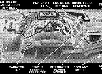
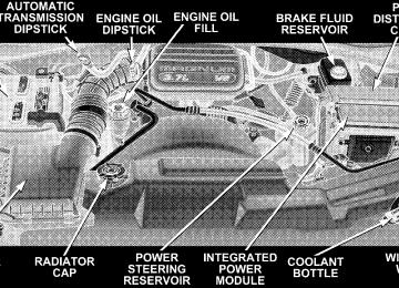
TO OPEN AND CLOSE THE HOOD To open the hood, two latches must be released. First pull the hood release lever located under the left side of the instrument panel.
UNDERSTANDING THE FEATURES OF YOUR VEHICLE 129
130 UNDERSTANDING THE FEATURES OF YOUR VEHICLE
Then push the safety latch lever to the left. It is located between the grille and hood opening right of the center.
NOTE: Ensure hood prop rod is fully seated into clip before closing hood to prevent damage to grille.
WARNING!
If the hood is not fully latched, it could fly up when the vehicle is moving and block your forward vision. Be sure all hood latches are fully latched before driving.
To prevent possible damage, do not slam the hood to close it. Use a firm downward push at the center front edge of the hood to ensure that both latches engage. Never drive your vehicle unless the hood is fully closed, with both latches engaged.
LIGHTS
UNDERSTANDING THE FEATURES OF YOUR VEHICLE 131
132 UNDERSTANDING THE FEATURES OF YOUR VEHICLE
Interior Lights
Courtesy and dome lights are turned on when the front doors are opened, when the dimmer control (rotating wheel on the right side of the switch) is rotated to the second upward detent position, or when the UNLOCK button is pressed on the key fob. When a door is open and the interior lights are on, rotating the dimmer control
all the way down to the OFF detent will cause all the interior lights to go out. This allows the doors to stay open for extended periods of time without discharging the vehicle’s battery. The brightness of the instrument panel lighting can be regulated by rotating the dimmer control up (brighter) or down (dimmer). When the headlights are ON you can supplement the brightness of the odometer, trip odom- eter, radio and overhead console by rotating the control up until you hear a click. This feature is termed the ⬙Parade⬙ mode and is useful when headlights are re- quired during the day. Battery Saver To protect the life of your vehicle’s battery, Load Shed- ding is provided for both the interior and exterior lights. If the ignition is off and any door is left ajar for eight minutes or the dimmer control is rotated upwards for 15
minutes, the interior lights will automatically turn off.If the headlights remain on while the ignition is cycled off, the exterior lights will automatically turn off after 8
minutes. If the headlights are turned on and left on for 8
minutes while the ignition is off, the exterior lights will automatically turn off. NOTE: Battery Saver mode is cancelled if the ignition is ON. NOTE: While the engine is running, the system will deactivate the Fog Lights and Heated seats if a low battery system voltage is detected. Headlight Delay To aid in your exit, your vehicle is equipped with a headlight delay that will leave the headlights on for 90
seconds. This delay is initiated when the ignition is cycled off while the headlight switch is on, and then the headlight switch is cycled off. The headlights will remainUNDERSTANDING THE FEATURES OF YOUR VEHICLE 133
on for 90 seconds. Headlight delay can be cancelled by either turning the headlight switch ON then OFF or by turning the ignition ON. NOTE: This feature can be disabled by your authorized dealer. Automatic Headlights — If Equipped Automatic Headlights can be activated by rotating the rotary headlight switch to the symbol “A.” The head- lights will turn on when the engine is running and the ambient light sensor indicates that the headlights should be activated. The headlights will turn off if the headlight switch is rotated to the off position or 90 seconds after the ignition is turned to OFF.
134 UNDERSTANDING THE FEATURES OF YOUR VEHICLE
Headlights, Parking Lights, Panel Lights
When the headlight switch is rotated to the first position to the right, the parking lights, taillights, side marker lights, license plate light and instrument panel lights are all turned on. The headlights will turn ON when the switch is rotated to the second position. Your vehicle is equipped with plastic headlight lenses that are lighter and less susceptible to stone breakage than glass headlights. Plastic is not as scratch resistant as glass and therefore different lens cleaning procedures must be followed. To minimize the possibility of scratching the lenses and reducing light output, avoid wiping with a dry cloth. To remove road dirt, wash with a mild soap solution fol- lowed by rinsing. Do not use abrasive cleaning components, solvents, steel wool or other abrasive materials to clean the lenses.
Illuminated Entry Headlights turn on for 90 seconds, when the Remote Keyless Entry UNLOCK button is pressed. NOTE: This feature can be activated by your authorized dealer. Daytime Running Lights (Canada Only) The headlights on your Durango will illuminate when the engine is started. This provides a constant “Lights ON” condition until the ignition is turned OFF. The lights illuminate at reduced intensity. If the parking brake is applied the Daytime Running Lights will turn off. If the headlights are activated, the Daytime Running Lights feature will transition to the normal headlight operating mode.
Lights-on Reminder If the headlights, parking lights, or courtesy lights are left On, after the ignition is turned Off, a continuous fast chime will sound when the driver’s door is opened. Fog Lights — If Equipped
UNDERSTANDING THE FEATURES OF YOUR VEHICLE 135
position and pressing the fog light button. The fog lights will operate only when the parking lights are ON or when the vehicle headlights are ON low beam. An indicator light located in the instrument cluster will illuminate when the fog lights are on. The fog lights will turn off when the switch is pressed in, when the head- light switch is rotated to the OFF position, or the high beam is selected.
MULTIFUNCTION CONTROL LEVER The multifunction control lever is located on the left side of the steering column.
The foglights are turned ON by placing the headlight rotary control in the parking light, headlight, or Auto
136 UNDERSTANDING THE FEATURES OF YOUR VEHICLE
Turn Signals
Move the lever up or down to signal a right-hand or left-hand turn. The arrow on either side of the instrument cluster flashes to indicate the direction of the turn, and proper operation
of the front and rear turn signal lights. If an indicator fails to light when the lever is moved, it would suggest that the switch or indicator lamp is defective. If a defective bulb or wiring circuit is detected for the turn signal system, the arrow indicators will flash at a faster rate. You can signal a lane change by moving the lever partially up or down. NOTE: duration, a continuous chime will sound. Passing Light You can signal another vehicle with your headlights by partially pulling the multifunction lever toward the steer- ing wheel. This will cause the high beam headlights to turn on until the lever is released.
If a turn signal has been left on for at least a mile
High Beam / Low Beam Select Switch Pull the multifunction control lever fully toward the steering wheel to switch the headlights from HIGH or LOW beam.
UNDERSTANDING THE FEATURES OF YOUR VEHICLE 137
Windshield Wipers
The wipers and washers are operated by a switch in the multifunction control lever. Turn the end of the handle to select the desired wiper speed. Intermittent Wiper System The intermittent feature of this system was designed for use when weather conditions make a single wiping cycle,
138 UNDERSTANDING THE FEATURES OF YOUR VEHICLE
with a variable pause between cycles, desirable. For maximum delay between cycles, rotate the control knob into the upper end of the delay range. The delay interval decreases as you rotate the knob until it enters the LO continual speed position. The delay can be regulated from a maximum of about 15 seconds between cycles, to a cycle every 2 seconds. The delay intervals will double in duration when the vehicle speed is 10 mph (16 km) or less.
WARNING!
Sudden loss of visibility through the windshield could lead to an accident. You might not see other vehicles or other obstacles. To avoid sudden icing of the windshield during freezing weather, warm the windshield with defroster before and during wind- shield washer use.
NOTE: Avoid using the wiper blades to remove frost or Ice from the windshield. If the front wiper is operating when the ignition NOTE: is turned off, the wiper will automatically return to the ⬙Park⬙ position. When the vehicle is restarted, the wipers will resume operation.
Windshield Washers To use the washer, push in on the washer knob on the end of the multifunction control lever and hold while spray is desired. If the washer knob is depressed while in the delay range, the wiper will operate for several seconds after the washer knob is released. It will then resume the intermittent interval previously selected. If the washer knob is pushed, for a period greater than 1 second, while in the OFF position, the wiper will wipe approximately three wipes, after the wash knob is released. To prevent freeze-up of your windshield washer system in cold weather, select a solution or mixture that meets or exceeds the temperature range of your climate. This rating information can be found on most washer fluid containers.
UNDERSTANDING THE FEATURES OF YOUR VEHICLE 139
ELECTRONIC STABILITY PROGRAM (ESP) OFF CONTROL SWITCH — IF EQUIPPED
ESP Off Control Switch
During normal driving conditions leave the ESP switch in the On position (indicator in cluster off). If the vehicle is 2WD and stuck or in a low traction condition such as
TILT STEERING COLUMN To tilt the column, push down on the lever below the turn signal control and move the wheel up or down, as desired.
140 UNDERSTANDING THE FEATURES OF YOUR VEHICLE
deep snow, sand, or gravel turn the system Off to improve traction. If the vehicle is 4WD, use 4HI position. When the ESP is switched off, the ESP/TCS Indicator light in the instrument cluster comes on. When the ESP is switched on, the Indicator light goes out.
To improve the vehicle’s traction when driving with snow chains, or starting off in deep snow, sand, or gravel, switch off the ESP by pressing the button switch. The ESP warning light will then be continuously illuminated. With the ESP system switched off, the engine torque reduction feature is desensitized. Therefore, the en- hanced vehicle stability offered by ESP is unavailable.
WARNING!
Tilting the steering column while the vehicle is moving is dangerous. Without a stable steering col- umn, you could lose control of the vehicle and have an accident. Adjust the column only while the ve- hicle is stopped. Be sure it is locked before driving.
UNDERSTANDING THE FEATURES OF YOUR VEHICLE 141
DRIVER ADJUSTABLE PEDALS — IF EQUIPPED
The power adjustable accelerator and brake pedals allow the driver to establish a comfortable position relative to the steering wheel and pedals.
142 UNDERSTANDING THE FEATURES OF YOUR VEHICLE
Adjustment
1. Position the driver seat so that you are at least 10
inches (254 mm) away from the airbag located in the center of the steering wheel. 2. Fasten and adjust the seatbelts. 3. Move the adjustable pedal switch, located to the left of the steering column near the parking brake release, up to move the pedals toward the driver or down to move the pedals away from the driver. 4. The pedals cannot be adjusted when the vehicle is in R (Reverse) or when the Speed Control is SET.CAUTION!
Do not place any article under the adjustable pedals or impede its ability to move as it may cause damage to the pedal controls. Pedal travel may become limited if movement is stopped by an obstruction in the adjustable pedal’s path.
ELECTRONIC SPEED CONTROL — IF EQUIPPED When engaged, this device takes over accelerator opera- tion at speeds greater than (refer to the table below for the speed for your specific engine). The controls are mounted on the steering wheel.
UNDERSTANDING THE FEATURES OF YOUR VEHICLE 143
To Set At A Desired Speed When the vehicle has reached the desired speed, press and release the SET button. Release the accelerator and the vehicle will operate at the selected speed. To Deactivate A soft tap on the brake pedal, normal braking, or pressing the CANCEL button will deactivate speed control with- out erasing the memory. Pushing the ON/OFF button to the OFF position or turning off the ignition erases the memory.
To Activate Push the ON/OFF button to the ON position. In the instrument cluster, the word “CRUISE” illuminates when the system is on.
144 UNDERSTANDING THE FEATURES OF YOUR VEHICLE
WARNING!
Leaving the Speed Control ON when not in use is dangerous. You could accidentally set the system to cause it to go faster than you want. You could lose control and have an accident. Always leave the system OFF when you aren’t using it.
To Resume Speed To resume a previously set speed, push and release the RESUME button. Resume can be used at any speed above (refer to the table below for the speed for your specific engine). To Vary The Speed Setting When the speed control is on, speed can be increased by pressing and holding the ACCEL button. When the button is released, a new set speed will be established.
Tapping the ACCEL button once will result in a speed increase (refer to the table below for the speed for your specific engine). Each time the button is tapped, speed increases so that tapping the button three times will increase speed by three increments. Tapping the DECEL button once will result in a speed decrease (refer to the table below for the speed for your specific engine). Each time the button is tapped, speed will decrease. For example, tapping the button 3 times will decrease the speed by 3 times the speed listed in the table below (refer to the table below for the speed for your specific engine). To decrease speed while the speed control is on, press and hold the DECEL button. Release the button when the desired speed is reached, and the new speed will be set.
UNDERSTANDING THE FEATURES OF YOUR VEHICLE 145
5.7L 25 mph (40 km/h) 20 mph (32 km/h) 1 mph (2 km/h) 1 mph (2 km/h) 20 mph (32 km/h)
4.7L 35 mph (56 km/h) 30 mph (50 km/h) 2 mph (3km/h) 1 mph (2 km/h) 30 mph (50 km/h) Vehicles equipped with a Automatic transmission may exhibit several downshifts under the above conditions. To reduce the frequency of the downshifts and to im- prove vehicle performance, it is advisable to lock out overdrive by pressing the “TOW/HAUL” button located at the end of the gear shifter.
3.7L 35 mph (56 km/h) 30 mph (50 km/h) 2 mph (3km/h) 1 mph (2 km/h) 30 mph (50 km/h)
Functions Engage Speed Minimun RESUME Speed ACCEL Increase DECEL Decrease Dropout Speed To Accelerate For Passing Depress the accelerator as you would normally. When the pedal is released, the vehicle will return to the set speed. NOTE: When driving uphill, at elevations above 2,000
feet (610 meters), or when the vehicle is heavily loaded (especially when towing) the vehicle may slow below the SET speed. If the vehicle speed drops below (refer to the table below for the speed for your specific engine), the speed control will automatically disengage. If this hap- pens, you can push down on the accelerator pedal to maintain the desired speed.146 UNDERSTANDING THE FEATURES OF YOUR VEHICLE
WARNING!
ABS (Anti-Lock Brake System)
This system aids the driver in maintaining vehicle control under adverse braking conditions. The system controls hydraulic brake pressure to prevent wheel lockup and help avoid skidding on slippery surfaces during braking. Refer to “Anti-Lock Brake System” in Section 5 of this manual for more information about ABS. NOTE: ABS improves steering control of the vehicle during hard braking maneuvers.
Speed Control can be dangerous where the system can’t maintain a constant speed. Your vehicle could go too fast for the conditions, and you could lose control. An accident could be the result. Don’t use Speed Control in heavy traffic or on roads that are winding, icy, snow-covered, or slippery.
ELECTRONIC BRAKE CONTROL SYSTEM Your vehicle is equipped with an advanced electronic brake control system that includes ABS (Anti-Lock Brake System), BAS (Brake Assist System), TCS (Traction Con- trol System), ERM (Electronic Roll Mitigation) and ESP (Electronic Stability Program). All five systems work together to enhance vehicle stability and control in vari- ous driving conditions, and are commonly referred to as ESP.
WARNING!
• Anti-lock system (ABS) cannot prevent the natu- ral laws of physics from acting on the vehicle, nor can it increase braking or steering efficiency be- yond that afforded by the condition of the vehicle brakes and tires or the traction afforded.
• The ABS cannot prevent accidents,
including those resulting from excessive speed in turns, following another vehicle too closely, or hydro- planing. Only a safe, attentive, and skillful driver can prevent accidents. • The capabilities of an ABS equipped vehicle must never be exploited in a reckless or dangerous manner which could jeopardize the user’s safety or the safety of others.
UNDERSTANDING THE FEATURES OF YOUR VEHICLE 147
BAS (Brake Assist System) – if equipped with ESP
ESP Off Switch Location
The BAS is designed to optimize the vehicle’s braking capability during emergency braking maneuvers. The system detects an emergency braking situation by sens- ing the rate and amount of brake application and then
148 UNDERSTANDING THE FEATURES OF YOUR VEHICLE
applies optimum pressure to the brakes. The system applies optimum pressure to the brakes in emergency braking conditions. This can help reduce braking dis- tances. The BAS complements the antilock brake system (ABS). Applying the brakes very quickly results in the best BAS assistance. To receive the benefit of the system, you must apply continuous braking pressure during the stopping sequence. Do not reduce brake pedal pressure unless braking is no longer desired. Once the brake pedal is released, the BAS is deactivated.
WARNING!
• BAS cannot prevent the natural laws of physics from acting on the vehicle, nor can it increase braking efficiency beyond that afforded by the condition of the vehicle brakes and tires or the traction afforded.
• The BAS cannot prevent accidents,
including those resulting from excessive speed in turns, following another vehicle too closely, or hydro- planing. Only a safe, attentive, and skillful driver can prevent accidents. • The capabilities of a BAS-equipped vehicle must never be exploited in a reckless or dangerous manner which could jeopardize the user’s safety or the safety of others.
TCS (Traction Control System) – if equipped with ESP
This system monitors the amount of wheel spin of each of the driven wheels. If wheel spin is detected, brake pressure is applied to the slipping wheel(s) and engine power is reduced to provide enhanced acceleration and stability. A feature of the TCS system functions similar to a limited slip differential and controls the wheel spin across a driven axle. If one wheel on a driven axle is spinning faster than the other, the system will apply the brake of the spinning wheel. This will allow more engine torque to be applied to the wheel that is not spinning. This feature remains active even if TCS and ESP are in the “Partial Off” mode. Refer to “ESP (Electronic Stability Program)” in this Section of this manual. This brake pressure modulation transfers drive torque from slipping to non-slipping wheels to provide optimal forward trac- tion.
UNDERSTANDING THE FEATURES OF YOUR VEHICLE 149
ERM (Electronic Roll Mitigation) This system anticipates the potential for wheel lift by monitoring the driver’s steering wheel input and the speed of the vehicle. When ERM determines that the rate of change of the steering wheel angle and vehicles speed are sufficient to potentially cause wheel lift, it applies the appropriate brake and may reduce engine power to lessen the chance that wheel lift will occur. ERM will only intervene during very severe or evasive driving maneu- vers. ERM can only reduce the chance of wheel lift occurring during severe or evasive driving maneuvers. It can not prevent wheel lift due to other factors such as road conditions, leaving the roadway or striking objects or other vehicles.
150 UNDERSTANDING THE FEATURES OF YOUR VEHICLE
WARNING!
Many factors, such as vehicle loading, road condi- tions and driving conditions, influence the chance that wheel lift or rollover may occur. • ERM can not prevent all wheel lift or rollovers, especially those that involve leaving the roadway or striking objects or other vehicles. Only a safe, attentive, and skillful driver can prevent acci- dents. • The capabilities of an ERM-equipped vehicle must never be exploited in a reckless or dangerous manner which could jeopardize the user’s safety or the safety of others.
ESP (Electronic Stability Program)
This system enhances directional control and stability of the vehicle under various driving conditions. ESP cor- rects for over/under steering of the vehicle by applying the brake of the appropriate wheel to assist in counter- acting the over/under steer condition. Engine power may also be reduced to help the vehicle maintain the desired path. ESP uses sensors in the vehicle to determine the vehicle path intended by the driver and compares it to the actual path of the vehicle. When the actual path does not match the intended path, ESP applies the brake of the appropri- ate wheel to assist in counteracting the oversteer or understeer condition. • Oversteer - when the vehicle is turning more than
appropriate for the steering wheel position.
• Understeer - when the vehicle is turning less than
appropriate for the steering wheel position.
ESP/TCS Indicator Light The ⬙ESP/TCS Indicator Light⬙ starts to flash as soon as the tires lose traction and the ESP system becomes active. The ⬙ESP/TCS Indicator Light⬙ also flashes when TCS is active. If the ⬙ESP/TCS Indicator Light⬙ begins to flash during acceleration, ease up on the accelerator and apply as little throttle as possible. Be sure to adapt your speed and driving to the prevailing road conditions.
UNDERSTANDING THE FEATURES OF YOUR VEHICLE 151
WARNING!
• ESP (Electronic Stability Program) cannot prevent the natural laws of physics from acting on the vehicle, nor can it increase the traction afforded. • ESP cannot prevent accidents, including those resulting from excessive speed in turns, or hydro- planing. Only a safe, attentive, and skillful driver can prevent accidents. • The capabilities of an ESP-equipped vehicle must never be exploited in a reckless or dangerous manner which could jeopardize the user’s safety or the safety of others.
The ESP system has 2 available operating modes.
152 UNDERSTANDING THE FEATURES OF YOUR VEHICLE
High Range (4WD Models) or 2WD Models
ON This is the normal operating mode for ESP in 4WD high range and in 2WD vehicles. Whenever the vehicle is started or the transfer case (if equipped) is shifted from 4WD low range or neutral back to 4WD high range, the ESP system will be in this mode. This mode should be used for most all driving situations. ESP should only be turned to “Partial Off” for specific reasons as noted below.
This mode is entered by momentarily depressing the “ESP OFF” Control Switch. When in “Partial Off” mode, the engine management portion of ESP has been desensitized, the thresh- olds for ESP activation are raised, and the “ESP/TCS Indicator Light” will be illuminated. This mode is intended to
Partial Off
be used if the vehicle is in deep snow, sand or gravel conditions and more wheel spin than ESP would nor- mally allow is required to gain traction. To turn ESP on again, momentarily depress the “ESP-Control OFF” Con- trol Switch. This will restore the normal “ON” mode of operation. ESP always operates under braking, even with the switch in the OFF-position.
WARNING!
In the Partial Off mode, the engine torque reduction and stability features are desensitized. Therefore, the enhanced vehicle stability offered by ESP is unavailable.
NOTE: To improve the vehicle’s traction when driving with snow chains, or starting off in deep snow, sand or gravel, it may be desirable to switch to the “Partial Off” mode by pressing the ESP Control Switch. Once the
UNDERSTANDING THE FEATURES OF YOUR VEHICLE 153
function returns to provide the stability feature at speeds above 30 mph (48 km/h). The ABS is in a special Off-Road mode that allows too look wheels at lower speed if gravel is detected to gain stopping distance. NOTE: When the vehicle is in 4WD low range, a feature of the ESP system remains active whether the ESP is on or off. This feature functions similar to a limited slip differ- ential and controls the wheel spin across an axle. If one wheel on an axle is spinning faster than the other, the system will apply the brake of the spinning wheel and allow more engine torque to be applied to the wheel that is not spinning.
situation requiring ESP to be switched to the “Partial Off” mode is overcome, turn ESP on by momentarily depress- ing the “ESP Control Switch”. This may be done with the vehicle is in motion. 4WD Low Range
Partial Off This is the normal operating mode for ESP in 4WD low range. Whenever the vehicle is started in 4WD low range or the transfer case (if equipped) is shifted from 4WD high range or neutral to 4WD low range, the ESP system will be in this mode. In 4WD low range, ESP function is desensitized until the vehicle reaches a speed of 30 mph (48 km/h). At 30 mph (48 km/h) the normal ESP stability function returns and the ESP/TCS Indicator Light” turns off. When the vehicle speed drops below 25 mph (40
km/h) the ESP system goes back to Partial Off. ESP is desensitized at low vehicle speeds in 4WD low range so that it will not interfere with off road driving but ESP154 UNDERSTANDING THE FEATURES OF YOUR VEHICLE
WARNING!
In the Partial Off mode, the engine torque reduction and stability features are desensitized. Therefore, the enhanced vehicle stability offered by ESP is unavailable.
ESP/BAS Warning Lamp and ESP/TCS Indicator Light The malfunction indicator for the ESP is combined with the BAS indicator. The yellow “ESP/BAS Warning Lamp” and the yellow “ESP/TCS Indicator Light” in the instrument cluster both come on when the ignition switch is turned to the “ON” position. They should both go out with the engine running. If the “ESP/BAS Warn- ing Lamp” comes on continuously with the engine running, a malfunction has been detected in either the ESP or BAS system, or both. If this light remains on after several ignition cycles, and the vehicle has been driven
several miles at speeds greater than 30 mph (48 km/h), see your authorized dealer as soon as possible to have the problem diagnosed and corrected. NOTE: • The “ESP Indicator Light” and the “ESP/BAS Warning Lamp” come on momentarily each time the ignition switch is turned ON. • Each time the ignition is turned ON, the ESP System • The ESP Control System will make buzzing or clicking sounds when it is active. This is normal; the sounds will stop when ESP becomes inactive following the maneuver that caused the ESP activation.
will be ON even if it was turned off previously.
OVERHEAD CONSOLE The overhead console has the following features:
• Courtesy Lights • Garage Door Opener — If Equipped • Compass/Temperature Mini-Trip Computer — If
Equipped
UNDERSTANDING THE FEATURES OF YOUR VEHICLE 155
Courtesy/Reading Lights Near the front of the console are two courtesy/reading lights. Both lights illuminate as courtesy lights when a door is opened, when the dimmer control is rotated to the courtesy light position (fully upward position), or when the UNLOCK button is pressed on the Remote Keyless Entry transmitter, if so equipped. These lights are also operated individually as reading lights by pressing the recessed area of the corresponding lens. NOTE: The courtesy/reading lights will remain on until the switch is pressed a second time, so be sure they have been turned off before leaving the vehicle. If the interior lights are left on after the vehicle is turned OFF, they will extinguish after 15 minutes.
156 UNDERSTANDING THE FEATURES OF YOUR VEHICLE
COMPASS/TEMPERATURE MINI-TRIP COMPUTER This feature allows you to choose between a compass/ temperature display and one of four trip conditions being monitored. US/M Button Use this button to change the display from U.S. to metric measurement units.
RESET Button
When this button is pressed you will hear a confirmation beep. Use this button to reset the following displays: Average Fuel Economy Trip Odometer Elapsed time.
Global Reset If the RESET button and STEP button are pressed at the same time and held for 3 seconds (you will hear a confirmation beep) and the Global Reset feature will reset the distance to empty (using a default fuel economy value), fuel economy, trip odometer, and elapsed time displays.
UNDERSTANDING THE FEATURES OF YOUR VEHICLE 157
Step Button
Use this button to choose or cycle through the four trip conditions.
158 UNDERSTANDING THE FEATURES OF YOUR VEHICLE
Average Fuel Economy (AVG ECO) Shows the average fuel economy since the last reset. This display mode becomes less sensitive to instantaneous changes in fuel consumption as the number of total vehicle miles since the last reset increases. It is suggested that this mode be reset periodically for general operation or when driving conditions change significantly (for example, at the end of a trip or when a trailer is connected or disconnected). Distance To Empty (DTE) Shows the estimated distance that can be travelled with the fuel remaining in the tank. The estimated distance is determined by a weighted average of the instantaneous and average fuel economy, according to the current fuel tank level. When Distance To Empty = 0, the fuel gauge pointer will initially be on the red “E” marker. At this point (fuel gauge pointer on the the red “E” marker) there is reserve
fuel capacity, which corresponds to approximately 5% of tank volume. This reserve capacity was put in place to prevent the likelihood of customers running out of fuel when operating at maximum load conditions in areas where there aren’t many gas stations. NOTE: The Distance To Empty will remain equal to zero, until the vehicle runs out of fuel or is refueled. Trip Odometer (ODO) This display shows the distance traveled since the last reset. Elapsed Time (ET) This display shows the accumulated ignition ON time since the last reset.
C/T Button
Compass/Temperature Display
UNDERSTANDING THE FEATURES OF YOUR VEHICLE 159
WARNING!
Even if the display still reads a few degrees above 32°F ( 0°C), the road surface may be icy, particularly in woods or on bridges. Drive carefully under such conditions to prevent an accident and possible per- sonal injury or property damage.
Automatic Compass Calibration This compass is self-calibrating which eliminates the need to manually set the compass. When the vehicle is new, the compass may appear erratic and the CAL symbol will be displayed.
Use this button to select a readout of the outside tem- perature and one of eight compass headings that indicate the direction in which the vehicle is facing.
160 UNDERSTANDING THE FEATURES OF YOUR VEHICLE
After completing one 360° turn, with the vehicle traveling less than 5 mph (8 km/h), in an area free from large metal or metallic objects, the CAL symbol will turn off and the compass will function normally. Manual Compass Calibration
NOTE: To ensure proper compass calibration, make sure the compass variance is properly set before manu- ally calibrating the compass. If the compass appears erratic and the CAL symbol does not appear, you must manually put the compass into the “Calibration” mode. To Put Into a Calibration Mode Turn on the ignition and set the display to “Compass/ Temperature.” Press and hold the RESET button for 5
seconds to change the display to VAR (compass variance) mode, holding the button 5 additional seconds will display CAL (compass calibration) mode. When the CALsymbol is displayed complete one 360 degree turn in an area free from large metal objects or power lines. The CAL symbol will turn off and the compass will function normally. Compass Variance is the difference between magnetic north and geographic north. In some areas of the country, the difference between magnetic and geographic north is great enough to cause the compass to give false readings. If this occurs, the compass variance must be set according to the Compass Variance Map.
UNDERSTANDING THE FEATURES OF YOUR VEHICLE 161
To set the variance: Turn the ignition ON and set the display to “Compass/Temperature.” Press and hold the RESET button approximately five seconds. The last vari- ance zone number will be displayed. Press the STEP button to select the new variance zone and press the RESET button to resume normal operation. Outside Temperature Because the ambient temperature sensor is located un- derhood, engine temperature can influence the displayed temperature, therefore, temperature readings are slowly updated when the vehicle speed is below 20 mph (30
km/h) or during stop and go driving.Compass Variance Map
162 UNDERSTANDING THE FEATURES OF YOUR VEHICLE
GARAGE DOOR OPENER — IF EQUIPPED The HomeLink威 Universal Transceiver replaces up to three remote controls (hand held transmitters) that oper- ate devices such as garage door openers, motorized gates, or home lighting. It triggers these devices at the push of a button. The Universal Transceiver operates off your vehicle’s battery and charging system; no batteries are needed.
For additional information on HomeLink威, call 1–800– 355–3515, or on the internet at www.homelink.com.
WARNING!
A moving garage door can cause injury to people and pets in the path of the door. People or pets could be seriously or fatally injured. Only use this transceiver with a garage door opener that has a “stop and reverse” feature as required by federal safety stan- dards. This includes most garage door opener mod- els manufactured after 1982. Do not use a garage door opener without these safety features it could cause injury or death. Call toll-free 1–800–355–3515
or, on the Internet at www.homelink.com for safety information or assistance.WARNING!
Programming HomeLink
UNDERSTANDING THE FEATURES OF YOUR VEHICLE 163
Vehicle exhaust contains carbon monoxide, a danger- ous gas. Do not run the vehicle’s exhaust while training the transceiver. Exhaust gas can cause seri-